EP3368237B1 - Verfahren zur herstellung eines bauteils für eine strömungsmaschine - Google Patents
Verfahren zur herstellung eines bauteils für eine strömungsmaschine Download PDFInfo
- Publication number
- EP3368237B1 EP3368237B1 EP17702810.7A EP17702810A EP3368237B1 EP 3368237 B1 EP3368237 B1 EP 3368237B1 EP 17702810 A EP17702810 A EP 17702810A EP 3368237 B1 EP3368237 B1 EP 3368237B1
- Authority
- EP
- European Patent Office
- Prior art keywords
- component
- fibers
- material fibers
- additive
- fiber composite
- Prior art date
- Legal status (The legal status is an assumption and is not a legal conclusion. Google has not performed a legal analysis and makes no representation as to the accuracy of the status listed.)
- Active
Links
Images

Classifications
-
- B—PERFORMING OPERATIONS; TRANSPORTING
- B22—CASTING; POWDER METALLURGY
- B22F—WORKING METALLIC POWDER; MANUFACTURE OF ARTICLES FROM METALLIC POWDER; MAKING METALLIC POWDER; APPARATUS OR DEVICES SPECIALLY ADAPTED FOR METALLIC POWDER
- B22F5/00—Manufacture of workpieces or articles from metallic powder characterised by the special shape of the product
- B22F5/009—Manufacture of workpieces or articles from metallic powder characterised by the special shape of the product of turbine components other than turbine blades
-
- B—PERFORMING OPERATIONS; TRANSPORTING
- B22—CASTING; POWDER METALLURGY
- B22F—WORKING METALLIC POWDER; MANUFACTURE OF ARTICLES FROM METALLIC POWDER; MAKING METALLIC POWDER; APPARATUS OR DEVICES SPECIALLY ADAPTED FOR METALLIC POWDER
- B22F12/00—Apparatus or devices specially adapted for additive manufacturing; Auxiliary means for additive manufacturing; Combinations of additive manufacturing apparatus or devices with other processing apparatus or devices
- B22F12/22—Driving means
-
- B—PERFORMING OPERATIONS; TRANSPORTING
- B22—CASTING; POWDER METALLURGY
- B22F—WORKING METALLIC POWDER; MANUFACTURE OF ARTICLES FROM METALLIC POWDER; MAKING METALLIC POWDER; APPARATUS OR DEVICES SPECIALLY ADAPTED FOR METALLIC POWDER
- B22F5/00—Manufacture of workpieces or articles from metallic powder characterised by the special shape of the product
- B22F5/04—Manufacture of workpieces or articles from metallic powder characterised by the special shape of the product of turbine blades
-
- B—PERFORMING OPERATIONS; TRANSPORTING
- B22—CASTING; POWDER METALLURGY
- B22F—WORKING METALLIC POWDER; MANUFACTURE OF ARTICLES FROM METALLIC POWDER; MAKING METALLIC POWDER; APPARATUS OR DEVICES SPECIALLY ADAPTED FOR METALLIC POWDER
- B22F7/00—Manufacture of composite layers, workpieces, or articles, comprising metallic powder, by sintering the powder, with or without compacting wherein at least one part is obtained by sintering or compression
- B22F7/06—Manufacture of composite layers, workpieces, or articles, comprising metallic powder, by sintering the powder, with or without compacting wherein at least one part is obtained by sintering or compression of composite workpieces or articles from parts, e.g. to form tipped tools
- B22F7/08—Manufacture of composite layers, workpieces, or articles, comprising metallic powder, by sintering the powder, with or without compacting wherein at least one part is obtained by sintering or compression of composite workpieces or articles from parts, e.g. to form tipped tools with one or more parts not made from powder
-
- C—CHEMISTRY; METALLURGY
- C22—METALLURGY; FERROUS OR NON-FERROUS ALLOYS; TREATMENT OF ALLOYS OR NON-FERROUS METALS
- C22C—ALLOYS
- C22C47/00—Making alloys containing metallic or non-metallic fibres or filaments
- C22C47/02—Pretreatment of the fibres or filaments
- C22C47/04—Pretreatment of the fibres or filaments by coating, e.g. with a protective or activated covering
-
- C—CHEMISTRY; METALLURGY
- C22—METALLURGY; FERROUS OR NON-FERROUS ALLOYS; TREATMENT OF ALLOYS OR NON-FERROUS METALS
- C22C—ALLOYS
- C22C47/00—Making alloys containing metallic or non-metallic fibres or filaments
- C22C47/02—Pretreatment of the fibres or filaments
- C22C47/06—Pretreatment of the fibres or filaments by forming the fibres or filaments into a preformed structure, e.g. using a temporary binder to form a mat-like element
- C22C47/062—Pretreatment of the fibres or filaments by forming the fibres or filaments into a preformed structure, e.g. using a temporary binder to form a mat-like element from wires or filaments only
- C22C47/064—Winding wires
-
- C—CHEMISTRY; METALLURGY
- C22—METALLURGY; FERROUS OR NON-FERROUS ALLOYS; TREATMENT OF ALLOYS OR NON-FERROUS METALS
- C22C—ALLOYS
- C22C47/00—Making alloys containing metallic or non-metallic fibres or filaments
- C22C47/14—Making alloys containing metallic or non-metallic fibres or filaments by powder metallurgy, i.e. by processing mixtures of metal powder and fibres or filaments
-
- C—CHEMISTRY; METALLURGY
- C22—METALLURGY; FERROUS OR NON-FERROUS ALLOYS; TREATMENT OF ALLOYS OR NON-FERROUS METALS
- C22C—ALLOYS
- C22C49/00—Alloys containing metallic or non-metallic fibres or filaments
- C22C49/14—Alloys containing metallic or non-metallic fibres or filaments characterised by the fibres or filaments
-
- B—PERFORMING OPERATIONS; TRANSPORTING
- B22—CASTING; POWDER METALLURGY
- B22F—WORKING METALLIC POWDER; MANUFACTURE OF ARTICLES FROM METALLIC POWDER; MAKING METALLIC POWDER; APPARATUS OR DEVICES SPECIALLY ADAPTED FOR METALLIC POWDER
- B22F10/00—Additive manufacturing of workpieces or articles from metallic powder
- B22F10/20—Direct sintering or melting
- B22F10/25—Direct deposition of metal particles, e.g. direct metal deposition [DMD] or laser engineered net shaping [LENS]
-
- B—PERFORMING OPERATIONS; TRANSPORTING
- B22—CASTING; POWDER METALLURGY
- B22F—WORKING METALLIC POWDER; MANUFACTURE OF ARTICLES FROM METALLIC POWDER; MAKING METALLIC POWDER; APPARATUS OR DEVICES SPECIALLY ADAPTED FOR METALLIC POWDER
- B22F10/00—Additive manufacturing of workpieces or articles from metallic powder
- B22F10/20—Direct sintering or melting
- B22F10/28—Powder bed fusion, e.g. selective laser melting [SLM] or electron beam melting [EBM]
-
- C—CHEMISTRY; METALLURGY
- C22—METALLURGY; FERROUS OR NON-FERROUS ALLOYS; TREATMENT OF ALLOYS OR NON-FERROUS METALS
- C22C—ALLOYS
- C22C49/00—Alloys containing metallic or non-metallic fibres or filaments
- C22C49/02—Alloys containing metallic or non-metallic fibres or filaments characterised by the matrix material
- C22C49/08—Iron group metals
-
- Y—GENERAL TAGGING OF NEW TECHNOLOGICAL DEVELOPMENTS; GENERAL TAGGING OF CROSS-SECTIONAL TECHNOLOGIES SPANNING OVER SEVERAL SECTIONS OF THE IPC; TECHNICAL SUBJECTS COVERED BY FORMER USPC CROSS-REFERENCE ART COLLECTIONS [XRACs] AND DIGESTS
- Y02—TECHNOLOGIES OR APPLICATIONS FOR MITIGATION OR ADAPTATION AGAINST CLIMATE CHANGE
- Y02P—CLIMATE CHANGE MITIGATION TECHNOLOGIES IN THE PRODUCTION OR PROCESSING OF GOODS
- Y02P10/00—Technologies related to metal processing
- Y02P10/25—Process efficiency
Definitions
- the present invention relates to a method for producing a component or a component part for a turbomachine.
- the present invention further comprises the component and a device for producing the component.
- the component can be the turbine disk.
- turbine disk is to be understood synonymously with turbine ring or rotor disk.
- the component can furthermore be a rotor part or a part of a compressor or compressor of a gas turbine.
- the component is preferably an additively or generatively manufactured or constructed component.
- layered, additive or generative manufacturing processes are in particular selective laser melting (SLM: English for “selective laser melting”), selective laser sintering (SLS: English for “selective laser sintering”) and electron beam melting (EBM: English for “electron beam melting”) ).
- Additive manufacturing processes are used to manufacture three-dimensional, individually shaped components through the iterative assembly or joining of layers, layered or volume elements, for example from a powder bed. Typical layer thicknesses of the individual layers are between 20 ⁇ m and 60 ⁇ m.
- a large number of different materials are available as starting materials, for example ceramic and / or metallic materials, which can be in powder or granulate form, but also in the form of fluids, for example as suspensions.
- the three-dimensional object is deposited one after the other through a large number of individual material layers on a lowerable construction platform and then individually are subjected to a locally selective solidification process.
- a method for selective laser melting is known from, for example EP 1 355 760 B1 , US 2007/051455 A1 or EP 2 962 789 A2 .
- Turbine parts are exposed to particularly high thermal and / or mechanical loads during their use or operation.
- Thermal and mechanical loads on a gas turbine or its rotor parts can be related during operation, for example in the form of thermomechanical stresses.
- One aspect of the present invention relates to a method for producing a component for a turbo machine, for example a gas turbine, such as a rotor disk for a gas turbine, comprising the additive construction of the component by means of an additive manufacturing method.
- the component for the additive construction is built up from a matrix or base material, preferably a powdery base material, for the component.
- Said material can be a nickel-based, a cobalt-based or an iron-based material.
- the method further includes the introduction of material fibers into a structure for the component during the additive structure in such a way that the material fibers are aligned along or essentially along a circumferential direction of the component, preferably around a component axis, and in such a way that a fiber composite material is formed, expediently comprising the material fibers and a base material strengthened by the additive build-up, the material fibers further comprising ceramic made of aluminum oxide, mullite, SiBCN, SiCN or SiC.
- the component is a rotatable part which, in particular, rotates when the turbomachine is in operation.
- the component is a rotationally symmetrical or essentially rotationally symmetrical part of or for the turbomachine.
- the circumferential direction preferably denotes a direction which corresponds to a direction of rotation or circumferential direction of the component in its operation, preferably in its use in the turbomachine.
- the circumferential direction can be a tangential direction.
- the circumferential direction can in particular describe a circumference of the component axis or at least partially include a geometric directional component along the circumference of the component.
- structure can refer to the component itself.
- Manufactured part of the component should be meant, for example at a point in time during additive manufacturing and in a corresponding system or device for additive manufacturing.
- the material fibers can be or will be oriented mainly or predominantly in or along the circumferential direction. For example, apart from necessary turns or manufacturing-related deviations from the circumferential direction, the material fibers can be aligned along this direction and / or incorporated into the structure. However, the material fibers do not necessarily have to be or become concentric with the component or other fibers.
- a fiber composite material or a fiber composite material can be manufactured or built up at least partially additively, or the corresponding manufacture can be implemented in an additive manufacturing process.
- the known advantages of fiber composite materials according to the method described can be used for production and use, in particular as a rotor part of a gas turbine, for example a compressor disk. For example, creep resistance or the resistance to tensile loading of the component perpendicular to the fiber direction can be improved through the use of fiber composite materials.
- the additive manufacturing method is a powder-bed-based additive manufacturing method.
- the additive manufacturing process is a jet melting process.
- the additive manufacturing process is selective laser melting, selective laser sintering, electron beam melting or laser deposition welding.
- the material fibers are introduced into the structure for the component by a robot-guided or robot-guided device.
- the material fibers viewed for example along a direction of construction of the component, are arranged or introduced only in one, in particular central, radial region of the component and preferably not over the entire radial extent.
- this area can be a radial “waist area” of the component, which is exposed to particularly high mechanical loads when the component is in operation.
- the material fibers are interwoven during the additive structure.
- the base material is at least partially arranged between the material fibers.
- the material fibers are provided with a coating before they are introduced.
- Another embodiment not claimed relates to a component for a turbomachine, the component being or being able to be produced by the method described.
- the component is a rotor part of a turbo machine, for example a gas turbine.
- the component is a turbine disk which is designed to hold a rotatable part of a turbo-engine in operation.
- the rotatable part can be a compressor blade, for example.
- a turbine disk for a turbomachine comprising, for example, in a radial area, in particular a central or central radial area, and a fiber composite material, as described above.
- the fiber composite material further comprises the material fibers and a matrix material, wherein the material fibers are aligned along a circumferential direction of the turbine disk and wherein the material fibers further comprise ceramic made of aluminum oxide, mullite, SiBCN, SiCN or SiC.
- the matrix material of the fiber composite material preferably designates a base material - solidified during or by the additive manufacturing.
- the material fibers comprise one or more of the following materials: carbon, boron, basalt and / or ceramic made of aluminum oxide, mullite, SiBCN, SiCN and SiC.
- the fiber composite material and / or the material fibers comprise carbon (C), silicon carbide (SiC) and / or aluminum oxide, for example Al 2 O 3 .
- the fiber composite material and / or the material fibers can comprise the materials mentioned as the main component, for example.
- the matrix and / or base material comprises carbon, silicon carbide and / or aluminum oxide.
- the matrix and / or base material can comprise the materials mentioned as the main component, for example.
- the coating of the material fibers comprises in particular carbon and / or boron nitride (BN).
- Another aspect of the present invention relates to a device for producing a component for a turbo machine, wherein the device is designed to additively build up the component from a base material, for example powdery.
- the device further comprises a device for introducing material fibers into the structure for the component in such a way that the material fibers are aligned along the circumferential direction of the component and in such a way that the fiber composite material is produced.
- the fiber composite material expediently comprises - as described above, the material fibers and the solidified base material.
- Figure 1 shows a schematic plan view of a device 10.
- the device 10 is a device for additive manufacturing of a component 1.
- the device 10 is preferably a device for building up a component layer by layer from a powder bed, for example a device for selective laser melting, as in FIG Figure 1 shown.
- the device 10 can be a device for selective laser sintering and / or for electron beam melting.
- the component 1 is in particular a rotor part of a turbomachine, such as a gas turbine.
- Component 1 preferably designates a turbine disk, a turbine ring or a rotor disk of a compressor of the turbine.
- the device 10 has a construction platform 8 (cf. Figure 2 ) on which a, preferably powdery, starting or base material 2 for the component 1 is arranged.
- the base material 2 can be, for example, a nickel-based, a cobalt-based or an iron-based material.
- a structure of the component is shown on the construction platform 8.
- it can be a partially assembled component and / or the component during its additive manufacturing.
- the component 1 is expediently designed to be rotationally symmetrical or essentially rotationally symmetrical.
- the component is also preferably rotatable, for example relative to stator components of the turbomachine. The component preferably rotates during normal operation of the turbine.
- the device 10 has a consolidation device 9. This can be a prior art consolidation device.
- the solidification device 9 is preferably a computer-controlled or computer-controllable unit which is equipped with a laser or an electron beam device (not explicitly identified) for solidifying the base material 2.
- the base material 2 is preferably first melted and then solidified.
- the device 10 has a coating or application device 7. Included it can be a doctor blade with which the, preferably powdery, base material 2 can be distributed or applied to the building platform 8. This can take place along a coating direction B, for example.
- the device 10 also has a device 5.
- the device 5 is designed to introduce material fibers 3 into the additive structure for the component 1 in such a way that the material fibers 3 are at least substantially aligned along a circumferential direction or direction of rotation of the component 1 denoted by the reference symbol A during operation.
- the dashed (concentric) circles which within the component 1 in Figure 1 are shown, preferably indicate an area in which the material fibers 3 are arranged and / or introduced.
- the material fibers are also shown only in sections. It can be seen from the sections shown that the direction of the orientation or alignment corresponds to the circumferential direction A.
- the device 5 is preferably also designed in such a way that, by introducing the material fibers 3, a fiber composite material 4 is created, comprising the material fibers 3 and a solidified base material or matrix material (for the sake of simplicity, this is referred to as the base material with the reference number 2).
- the fiber composite material 4 can be formed by the material fibers 3 and the matrix material.
- the device 5 is preferably robot-controlled.
- the device 5 can comprise a robot arm which is only indicated schematically in the figure.
- This robot arm can be pivoted, for example, over the manufacturing space or the construction platform 8 or the component 1 in such a way that the material fibers 3 can be "built into” the component as described above during the additive construction of the base material.
- the said robotic arm can furthermore, for example, be designed to be extendable in a telescopic manner.
- the material fibers 3 - with the aid of the device 5 - are preferably introduced into the structure during the additive construction or the additive production of the component 1, so that the fiber composite material 4 is created and the fibers are aligned as described above.
- One fiber layer (cf. Figure 1 ) are introduced. This is preferably done before the base material 2 is applied or distributed by means of the coating device 7, so that a corresponding layer for the fiber composite material can be formed or produced.
- the base material 2 is preferably applied and / or the material fibers are introduced in such a way that the base material 2 is at least partially arranged between the material fibers 3.
- the material fibers 3 can also be woven with one another.
- the material fibers In the context of the method described, provision is also made for the material fibers to be provided or coated with a coating (not explicitly identified), for example before they are introduced into the structure by the device 5.
- the coating can be a sliding or lubricating coating, in particular to enable a sliding movement of the material fibers 3 relative to the matrix material 2, which in turn brings about the special mechanical properties of the fiber composite material 4.
- Figure 2 shows a schematic side view of a device 10.
- the reference character C denotes a construction direction.
- the device 10 for example, also a device for laser deposition welding, in particular Laser powder deposition welding.
- the consolidation device 9 here preferably comprises both a laser (not explicitly identified) for consolidating the base material 2 and a powder nozzle (not explicitly identified) with which the base material 2 is provided.
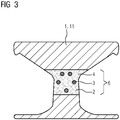
- Figure 3 shows a finished component 1 in a simplified cross section.
- the component 1 has a central or inner radial region 6 that is narrowed and / or tapered compared to the other sections. Particularly high mechanical loads can occur in this area when the component 1 is in operation.
- An upper, unmarked, widening area of the turbine disk 1 is provided in particular both to hold turbine blades in place, for example during operation of a gas turbine, and to hold the turbine blades, preferably by axially sliding them into or out of the cavities formed to make interchangeable.
- the central region 6 comprises the fiber composite material 4 described.
- the central region 6 can consist of the fiber composite material 4.
- the material fibers 3 are shown in a circle in the area 6.
- the fiber composite material 4 and / or the component provided with it has in particular - compared to a turbine disk of the prior art - improved mechanical properties, in particular a higher elongation at break or tensile strength at break, for example by up to one percent.
- the component 1 according to the invention produced with the method described preferably has a significantly increased crack resistance, an improved thermal shock resistance and, for example, improved thermomechanical properties.
- the extensibility or extensibility of the component 1 can be increased by 2% relative to a conventional rotor part of a turbine.
- the fiber composite material 4 can - by specifying the fiber directions - have anisotropic and, in particular, nevertheless improved mechanical properties.
- the component 1 can in particular be a rotor disk of a compressor or a compressor stage of a gas turbine (preferably upstream of the combustion chamber of the turbine, viewed in the direction of flow).
- the component 1 can be a compressor rotor disk of the material class “26NiCrMoV 14-5” or “Cost-E (X l 2CrMoWVNbN 10-1-1)”.
- the material fibers 3 described can furthermore comprise one or more of the following materials: carbon, boron, basalt and / or ceramic aluminum oxide, for example Al 2 O 3 , mullite, SiBCN, SiCN and SiC.
Landscapes
- Chemical & Material Sciences (AREA)
- Engineering & Computer Science (AREA)
- Mechanical Engineering (AREA)
- Materials Engineering (AREA)
- Metallurgy (AREA)
- Organic Chemistry (AREA)
- Manufacturing & Machinery (AREA)
- Composite Materials (AREA)
- Crystallography & Structural Chemistry (AREA)
- Turbine Rotor Nozzle Sealing (AREA)
- Powder Metallurgy (AREA)
- Structures Of Non-Positive Displacement Pumps (AREA)
- Manufacture Of Alloys Or Alloy Compounds (AREA)
Description
- Die vorliegende Erfindung betrifft ein Verfahren zur Herstellung einer Komponente oder eines Bauteils für eine Strömungsmaschine. Weiterhin umfasst die vorliegende Erfindung das Bauteil und eine Vorrichtung zur Herstellung des Bauteils.
- Bei dem Bauteil kann es sich um die Turbinenscheibe handeln. Der Begriff "Turbinenscheibe" ist vorliegend synonym mit Turbinenring oder Rotorscheibe zu verstehen. Das Bauteil kann weiterhin ein Rotorteil oder ein Teil eines Kompressors oder Verdichters einer Gasturbine sein. Weiterhin handelt es sich bei dem Bauteil vorzugsweise um ein additiv oder generativ hergestelltes oder aufgebautes Bauteil.
- Bekannte schichtweise, additive oder generative Herstellungsverfahren sind insbesondere das selektive Laserschmelzen (SLM: englisch für "selective laser melting"), selektive Lasersintern (SLS: englisch für "selective laser sintering") und das Elektronenstrahlschmelzen (EBM: englisch für "electron beam melting"). Additive Fertigungsverfahren werden durch ihr iteratives Auf- oder Aneinanderfügen von Lagen, Schicht- oder Volumenelementen, beispielsweise aus einem Pulverbett, zur Herstellung dreidimensionaler individuell geformter Bauteile. Typische Schichtdicken der einzelnen Lagenliegen zwischen 20 µm und 60 µm.
- Als Ausgangsmaterialien steht eine Vielzahl unterschiedlicher Werkstoffe, beispielsweise keramische und/oder metallische Werkstoffe, zur Verfügung, die sowohl in Pulver- oder Granulatform, aber auch in Form von Fluiden bspw. als Suspensionen, vorliegen können. Bei generativen Herstellungsverfahren, wird der dreidimensionale Gegenstand durch eine Vielzahl einzelner Materialschichten, die auf einer absenkbaren Bauplattform nacheinander abgeschieden und anschließend einzeln einem lokal selektiven Verfestigungsprozess unterzogen werden, gebildet.
- Ein Verfahren zum selektiven Laserschmelzen ist beispielsweise bekannt aus
EP 1 355 760 B1 ,US 2007/051455 A1 oderEP 2 962 789 A2 . - Turbinenteile sind während ihres Einsatzes oder Betriebs besonders hohen thermischen und/oder mechanischen Belastungen ausgesetzt. Dabei können thermische und mechanische Belastungen einer Gasturbine oder seiner Rotorteile während des Betriebs zusammenhängen, beispielsweise in Form von thermomechanischen Spannungen.
- Neben der Entwicklung von immer temperaturresistenten Werkstoffen besteht daher auch ein Bedarf an Materialien, beispielsweise Verbundwerkstoffen, welche verbesserte mechanische Eigenschaften aufweisen. Während in thermisch hochbelasteten Bereichen einer Turbine, beispielsweise mit Temperaturen oberhalb von 600 °C, eine hohe Festigkeit der Materialien gefordert wird, wird insbesondere in inneren Bereichen oder inneren Teilen der Turbine, des Kompressors oder einer entsprechenden Rotorscheibe eine hohe Zähigkeit gefordert.
- Es ist daher eine Aufgabe der vorliegenden Erfindung, Mittel anzugeben, die die mechanischen Eigenschaften, insbesondere von rotierbaren Turbinenteilen verbessern und/oder den Betrieb der Turbine zuverlässiger und/oder effizienter zu machen.
- Diese Aufgabe wird durch den Gegenstand der unabhängigen Ansprüche gelöst. Vorteilhafte Ausgestaltungen sind Gegenstand der abhängigen Patentansprüche.
- Ein Aspekt der vorliegenden Erfindung betrifft ein Verfahren zur Herstellung eines Bauteils für eine Strömungsmaschine, beispielsweise eine Gasturbine, wie eine Rotorscheibe für eine Gasturbine, umfassend das additive Aufbauen des Bauteils mittels eines additiven Herstellungsverfahrens. Insbesondere wird das Bauteil für das additive Aufbauen aus einem Matrix- oder Basismaterial, vorzugsweise einem pulverförmigen Basismaterial, für das Bauteil aufgebaut. Das genannte Material kann ein nickelbasiertes, ein kobaltbasiertes oder ein eisenbasiertes Material sein.
- Das Verfahren umfasst weiterhin das Einbringen von Materialfasern in einen Aufbau für das Bauteil während des additiven Aufbauens derart, dass die Materialfasern entlang oder im Wesentlichen entlang einer Umfangsrichtung des Bauteils, vorzugsweise um eine Bauteilachse herum, ausgerichtet sind und derart, dass ein Faserverbundmaterial entsteht, zweckmäßigerweise umfassend die Materialfasern und ein durch das additive Aufbauen verfestigtes Basismaterial, wobei die Materialfasern weiterhin Keramik aus Aluminiumoxid, Mullit, SiBCN, SiCN oder SiC, umfassen.
- In einer nicht beanspruchten Ausgestaltung ist das Bauteil ein rotierbares und insbesondere im Betrieb der Strömungsmaschine rotierendes Teil.
- In einer nicht beanspruchten Ausgestaltung ist das Bauteil ein rotationssymmetrisches oder im Wesentlichen rotationssymmetrisches Teil der oder für die Strömungsmaschine.
- Die Umfangsrichtung bezeichnet vorliegend vorzugsweise eine Richtung, welche einer Rotation- oder Umlaufrichtung des Bauteils in seinem Betrieb, vorzugsweise in seinem Einsatz in der Strömungsmaschine entspricht. Die Umfangsrichtung kann eine Tangentialrichtung sein.
- Die Umfangsrichtung kann insbesondere einen Umfang der Bauteilachse beschreiben oder zumindest teilweise eine geometrische Richtungskomponente entlang des Umfangs des Bauteils umfassen.
- Der Begriff "Aufbau" kann das Bauteil an sich bezeichnen.
- Insbesondere kann damit ein lediglich teilweise (additiv) hergestellter Teil des Bauteils gemeint sein, beispielsweise zu einem Zeitpunkt während einer additiven Herstellung und in einer entsprechenden Anlage oder Vorrichtung zur additiven Herstellung.
- Die Materialfasern können hauptsächlich oder überwiegend in oder entlang der Umfangsrichtung ausgerichtet sein oder werden. Beispielsweise können die Materialfasern abgesehen von notwendigen Windungen oder herstellungsbedingten Abweichungen von der Umfangsrichtung entlang dieser Richtung ausgerichtet sein und/oder in den Aufbau eingebracht werden. Jedoch müssen die Materialfasern nicht zwingend konzentrisch zu dem Bauteil oder anderen Fasern ausgerichtet sein oder werden.
- Durch das beschriebene Verfahren kann mit besonderem Vorteil ein Faserverbundmaterial bzw. ein Faserverbundwerkstoff zumindest teilweise additiv hergestellt oder aufgebaut, oder die entsprechende Herstellung in einen additiven Fertigungsprozess implementiert werden. Insbesondere können die bekannten Vorteile von Faserverbundwerkstoffen gemäß dem beschriebenen Verfahren für die Herstellung und den Einsatz insbesondere als Rotorteil einer Gasturbine, beispielsweise einer Kompressorscheibe genutzt werden. Beispielsweise kann eine Kriechbeständigkeit oder die Beständigkeit gegen eine Zugbelastung des Bauteils senkrecht zur Faserrichtung durch den Einsatz von Faserverbundwerkstoffen verbessert werden.
- Gleichzeitig können dabei synergisch ebenfalls die Vorteile additiver Herstellungstechnologie genutzt werden.
- In einer Ausgestaltung ist das additive Herstellungsverfahren ein pulverbett-basiertes additives Herstellungsverfahren.
- In einer Ausgestaltung ist das additive Herstellungsverfahren ein Strahlschmelzverfahren.
- In einer Ausgestaltung ist das additive Herstellungsverfahren selektives Laserschmelzen, selektives Lasersintern, Elektronenstrahlschmelzen oder Laserauftragschweißen.
- In einer Ausgestaltung werden die Materialfasern durch eine robotergeführte oder robotergeführte Einrichtung in den Aufbau für das Bauteil eingebracht.
- In einer Ausgestaltung werden die Materialfasern, beispielsweise entlang einer Aufbaurichtung des Bauteils betrachtet, lediglich in einem, insbesondere zentralen, radialen Bereich des Bauteils und vorzugsweise nicht über die gesamte radiale Ausdehnung hinweg angeordnet oder eingebracht. Insbesondere kann es sich bei diesem Bereich um einen radialen "Taillenbereich" des Bauteils handeln, welcher im Betrieb des Bauteils besonders hohen mechanischen Belastungen ausgesetzt ist.
- In einer Ausgestaltung werden die Materialfasern während des additiven Aufbaus miteinander verwoben.
- In einer Ausgestaltung wird das Basismaterial zumindest teilweise zwischen den Materialfasern angeordnet.
- In einer Ausgestaltung werden die Materialfasern vor dem Einbringen mit einer Beschichtung versehen.
- Eine weitere nicht beanspruchte Ausgestaltung betrifft ein Bauteil für eine Strömungsmaschine, wobei das Bauteil durch das beschriebene Verfahren hergestellt oder herstellbar ist.
- In einer nicht beanspruchten Ausgestaltung ist das Bauteil ein Rotorteil einer Strömungsmaschine, beispielsweise einer Gasturbine.
- In einer nicht beanspruchten Ausgestaltung ist das Bauteil eine Turbinenscheibe, welche zum Halten eines rotierbaren Teils einer Strömungsmaschine im Betrieb ausgebildet ist. Bei dem rotierbaren Teil kann es sich beispielsweise um einer Kompressorschaufel handeln.
- Eine weitere nicht beanspruchte Ausgestaltung betrifft eine Turbinenscheibe für eine Strömungsmaschine umfassend, beispielsweise in einen radialen Bereich, insbesondere einem zentralen oder mittleren radialen Bereich und ein Faserverbundmaterial, wie oben beschrieben. Das Faserverbundmaterial umfasst weiterhin die Materialfasern und ein Matrixmaterial, wobei die Materialfasern entlang einer Umfangsrichtung der Turbinenscheibe ausgerichtet sind und wobei die Materialfasern weiterhin Keramik aus Aluminiumoxid, Mullit, SiBCN, SiCN oder SiC umfassen.
- Das Matrixmaterial des Faserverbundmaterials bezeichnet vorzugsweise ein - während der oder durch die additive Herstellung verfestigtes - Basismaterial.
- In einer Ausgestaltung umfassen die Materialfasern eines oder mehrere der folgenden Materialien: Kohlenstoff, Bor, Basalt und/oder Keramik aus Aluminiumoxid, Mullit, SiBCN, SiCN und SiC.
- In einer Ausgestaltung umfasst das Faserverbundmaterial und/oder die Materialfasern Kohlenstoff (C), Siliziumcarbid (SiC) und/oder Aluminiumoxid, beispielsweise Al2O3. Das Faserverbundmaterial und/oder die Materialfasern können die genannten Materialien beispielsweise als Hauptbestandteil umfassen.
- In einer Ausgestaltung umfasst das Matrix- und/oder Basismaterial, Kohlenstoff, Siliziumcarbid und/oder Aluminiumoxid. Das Matrix- und/oder Basismaterial kann die genannten Materialien beispielsweise als Hauptbestandteil umfassen.
- In einer nicht beanspruchten Ausgestaltung umfasst die Beschichtung der Materialfasern insbesondere Kohlenstoff und/oder Bornitrid (BN).
- Ein weiterer Aspekt der vorliegenden Erfindung betrifft eine Vorrichtung zur Herstellung eines Bauteils für eine Strömungsmaschine, wobei die Vorrichtung ausgebildet ist, das Bauteil additiv aus einem, beispielsweise pulverförmigen, Basismaterial aufzubauen. Die Vorrichtung umfasst weiterhin eine Einrichtung zum Einbringen von Materialfasern in den Aufbau für das Bauteil derart, dass die Materialfasern entlang der Umfangsrichtung des Bauteils ausgerichtet sind und derart, dass das Faserverbundmaterial entsteht. Das Faserverbundmaterial umfasst zweckmäßigerweise - wie oben beschrieben die Materialfasern und das verfestigte Basismaterial.
- Ausgestaltungen, Merkmale und/oder Vorteile, die sich vorliegend auf das Verfahren beziehen, können sich ferner die Vorrichtung und/oder das Bauteil betreffen, und umgekehrt.
- Weitere Einzelheiten der Erfindung werden nachfolgend anhand der Zeichnung beschrieben.
- Figur 1
- zeigt schematisch eine Aufsicht auf eine Vorrichtung zur additiven Herstellung eines Bauteils für eine Strömungsmaschine.
- Figur 2
- zeigt schematisch eine Schnitt- oder Seitenansicht einer Vorrichtung zur additiven Herstellung eines Bauteils für eine Strömungsmaschine.
- Figur 3
- zeigt schematisch einen Querschnitt durch eine Turbinenscheibe.
-
Figur 1 zeigt schematisch eine Aufsicht auf eine Vorrichtung 10. Die Vorrichtung 10 ist eine Vorrichtung zur additiven Herstellung eines Bauteils 1. Die Vorrichtung 10 ist vorzugsweise eine Vorrichtung zum schichtweisen Aufbau eines Bauteils aus einem Pulverbett, beispielsweise eine Vorrichtung zum selektiven Laserschmelzen, wie inFigur 1 dargestellt. Alternativ kann es sich bei der Vorrichtung 10 um eine Vorrichtung zum selektiven Lasersintern und/oder zum Elektronenstrahlschmelzen handeln. - Anhand der Vorrichtung 10 und der
Figuren 1 und 2 wird ein erfindungsgemäßes Verfahren zur Herstellung des Bauteils 1 beschrieben. - Das Bauteil 1 ist insbesondere ein Rotorteil einer Strömungsmaschine, wie einer Gasturbine. Vorzugsweise bezeichnet das Bauteil 1 eine Turbinenscheibe, einen Turbinenring oder eine Rotorscheibe eines Kompressors der Turbine.
- Die Vorrichtung 10 weist eine Bauplattform 8 (vgl.
Figur 2 ) auf, auf der ein, vorzugsweise pulverförmiges, Ausgangs- oder Basismaterial 2 für das Bauteil 1 angeordnet ist. Das Basismaterial 2 kann beispielsweise ein nickelbasiertes, ein kobaltbasiertes oder ein eisenbasiertes Material sein. - Auf der Bauplattform 8 ist ein Aufbau des Bauteils gezeigt. Insbesondere kann es sich dabei um ein teilweise aufgebautes Bauteil und/oder um das Bauteil während seiner additiven Herstellung handeln. Das Bauteil 1 ist zweckmäßigerweise rotationssymmetrisch oder im Wesentlichen rotationssymmetrisch ausgestaltet. Als Rotorteil einer Strömungsmaschine oder eines Kompressors derselben ist das Bauteil ferner vorzugsweise rotierbar, bspw. relativ zu Statorkomponenten der Strömungsmaschine. Vorzugsweise rotiert das Bauteil während des bestimmungsgemäßen Betriebs der Turbine.
- Für den additiven Aufbau weist die Vorrichtung 10 eine Verfestigungseinrichtung 9 auf. Dabei kann es sich um eine Verfestigungseinrichtung des Standes der Technik handeln. Vorzugsweise ist die Verfestigungseinrichtung 9 eine computergesteuerte oder -steuerbare Einheit, welche zum Verfestigen des Basismaterials 2 mit einem Laser oder einer Elektronenstrahleinrichtung (nicht explizit gekennzeichnet) ausgerüstet ist. Für das Verfestigen wird das Basismaterial 2 vorzugsweise zunächst aufgeschmolzen und anschließend erstarrt.
- Zur Aufbringung des Basismaterials 2 weist die Vorrichtung 10 eine Beschichtungs- oder Auftragungseinrichtung 7 auf. Dabei kann es sich um eine Rakel handelt, mit welcher das, vorzugsweise pulverförmige, Basismaterial 2 auf der Bauplattform 8 verteilt oder aufgetragen werden kann. Dies kann beispielsweise entlang einer Beschichtungsrichtung B erfolgen.
- Als erfindungsgemäßes Element weist die Vorrichtung 10 weiterhin eine Einrichtung 5 auf. Die Einrichtung 5 ist ausgebildet, Materialfasern 3 in den additiven Aufbau für das Bauteil 1 einzubringen, und zwar derart, dass die Materialfasern 3 zumindest im Wesentlichen entlang einer mit dem Bezugszeichen A bezeichneten Umfangsrichtung oder Rotationsrichtung des Bauteils 1 im Betrieb ausgerichtet sind.
- Die gestrichelten (konzentrischen) Kreise, welche innerhalb des Bauteils 1 in
Figur 1 gezeigt sind, deuten vorzugsweise einen Bereich an in dem die Materialfasern 3 angeordnet und/oder eingebracht werden. Lediglich abschnittsweise sind ebenfalls die Materialfasern dargestellt. Anhand der gezeigten Abschnitte ist zu erkennen, dass die Richtung der Orientierung oder Ausrichtung der Umfangsrichtung A entspricht. - Die Einrichtung 5 ist vorzugsweise weiterhin derart ausgebildet, dass, durch das Einbringen der Materialfasern 3, ein Faserverbundmaterial 4 entsteht, umfassend die Materialfasern 3 und ein verfestigtes Basismaterial oder Matrixmaterial (dieses ist der Einfachheit halber ebenso wie das Basismaterial mit dem Bezugszeichen 2 bezeichnet). Das Faserverbundmaterial 4 kann durch die Materialfasern 3 und das Matrixmaterial gebildet werden.
- Die Einrichtung 5 ist vorzugsweise robotergesteuert. Wie in
Figur 1 dargestellt kann die Einrichtung 5 einen Roboterarm umfassen welcher in der Abbildung lediglich schematisch angedeutet ist. Dieser Roboterarm ist beispielsweise derart über den Herstellungsraum oder die Bauplattform 8 bzw. das Bauteil 1 schwenkbar, dass die Materialfasern 3 während des additiven Aufbauens des Basismaterials in das Bauteil wie oben beschrieben "eingebaut" werden können. Der genannte Roboterarm kann weiterhin beispielsweise teleskopartig verlängerbar ausgestaltet sein. - Im Rahmen des vorliegenden Verfahrens werden die Materialfasern 3 - mithilfe der Einrichtung 5 - vorzugsweise während des additiven Aufbaus oder der additiven Herstellung des Bauteils 1 in den Aufbau eingebracht, so dass das Faserverbundmaterial 4 entsteht und die die Fasern ebenso wie oben beschrieben ausgerichtet werden. Pro additiv aufgebauter und/oder verfestigter Lage von Basismaterial kann eine Faserlage (vergleiche
Figur 1 ) eingebracht werden. Dies geschieht vorzugsweise bevor das Basismaterial 2 mittels der Beschichtungseinrichtung 7 aufgetragen oder verteilt wird, sodass eine entsprechende Schicht für das Faserverbundmaterial gebildet oder hergestellt werden kann. Vorzugsweise wird das Basismaterial 2 derart aufgetragen und/oder werden die Materialfasern derart eingebracht, dass zwischen den Materialfasern 3 zumindest teilweise Basismaterial 2 angeordnet ist. - Insbesondere können die Materialfasern 3 auch miteinander verwoben werden.
- Es ist im Rahmen des beschriebenen Verfahrens auch vorgesehen, dass die Materialfasern, beispielsweise vor dem Einbringen in den Aufbau durch die Einrichtung 5, mit einer Beschichtung (nicht explizit gekennzeichnet) versehen oder beschichtet werden. Bei der Beschichtung kann es sich um eine Gleit- oder Schmierbeschichtung handelt, insbesondere um eine Gleitbewegung der Materialfasern 3 relativ zu dem Matrixmaterial 2 zu ermöglichen, welche wiederum die besonderen mechanischen Eigenschaften des Faserverbundmaterials 4 bewirkt.
-
Figur 2 zeigt eine schematische Seitenansicht einer Vorrichtung 10. Mit dem Bezugszeichen C ist eine Aufbaurichtung bezeichnet. Als Alternative zu der Ausgestaltung der Vorrichtung ausFigur 1 kann - wie inFigur 2 gezeigt - die Vorrichtung 10 beispielsweise ebenfalls eine Vorrichtung zum Laserauftragschweißen, insbesondere Laserpulverauftragschweißen, sein. Dementsprechend umfasst die Verfestigungseinrichtung 9 hier vorzugsweise sowohl einen Laser (nicht explizit gekennzeichnet) zum Verfestigen des Basismaterials 2 als auch eine Pulverdüse (nicht explizit gekennzeichnet) mit der das Basismaterial 2 bereitgestellt wird. -
Figur 3 zeigt in einem vereinfachten Querschnitt ein fertig hergestelltes Bauteil 1. Das Bauteil 1 weist einen - im Vergleich zu den übrigen Abschnitten verschmälerten und/oder taillierten zentralen, oder inneren radialen Bereich 6 auf. In diesem Bereich können im Betrieb des Bauteils 1 besonders hohe mechanische Belastungen auftreten. Ein oberer, nicht gekennzeichneter, sich verbreiternder Bereich der Turbinenscheibe 1 ist insbesondere vorgesehen sowohl um Turbinenschaufeln beispielsweise im Betrieb einer Gasturbine an Ort und Stelle zu halten, als auch die Turbinenschaufeln, vorzugsweise durch axiales Ein- oder Ausschieben in die bzw. aus den gebildeten Hohlräume, austauschbar zu machen. - Der zentrale Bereich 6 umfasst das beschriebene Faserverbundmaterial 4. Der zentrale Bereich 6 kann aus dem Faserverbundmaterial 4 bestehen. Insbesondere sind in der Querschnittsdarstellung der Figur 4 in dem Bereich 6 die Materialfasern 3 kreisförmig dargestellt. Das Faserverbundmaterial 4 und/oder das damit versehene Bauteil weist insbesondere - im Vergleich zu einer Turbinenscheibe des Standes der Technik - verbesserte mechanische Eigenschaften, insbesondere eine höhere Bruchdehnung oder Bruchdehn-Belastbarkeit, bspw. um bis zu einem Prozent, auf. Ebenso hat das mit dem beschriebenen Verfahren hergestellte, erfindungsgemäße Bauteil 1 vorzugsweise einen signifikant erhöhten Risswiderstand, eine verbesserte Thermoschockbeständigkeit, als auch beispielsweise verbesserte thermomechanische Eigenschaften.
- Weiterhin kann eine Dehnbarkeit oder Dehn-Belastbarkeit des Bauteils 1 relativ zu einem herkömmlichen Rotorteil einer Turbine um 2 % erhöht sein.
- Das Faserverbundmaterial 4 kann - durch die Vorgabe der Faserrichtungen - anisotrope und insbesondere dennoch verbesserte mechanische Eigenschaften aufweisen.
- Bei dem Bauteil 1 kann es sich insbesondere um eine Rotorscheibe eines Kompressors oder einer Kompressorstufe einer Gasturbine (vorzugsweise in Strömungsrichtung betrachtet vor der Brennkammer der Turbine) handeln. Insbesondere kann das Bauteil 1 eine Kompressor-Rotorscheibe der Materialklasse "26NiCrMoV 14-5" oder "Cost-E (X l 2CrMoWVNbN 10-1-1)" sein. Die beschriebenen Materialfasern 3 können weiterhin eines oder mehrere der folgenden Materialien umfassen: Kohlenstoff, Bor, Basalt und/oder Keramik Aluminiumoxid, beispielsweise Al2O3, Mullit, SiBCN, SiCN und SiC.
Claims (6)
- Verfahren zur Herstellung eines Bauteils (1) für eine Strömungsmaschine umfassend die folgenden Schritte:- additives Aufbauen des Bauteils mittels eines additiven Herstellungsverfahrens aus einem Basismaterial (2) für das Bauteil (1) und- Einbringen von Materialfasern (3) in einen Aufbau für das Bauteil (1) während des additiven Aufbauens derart, dass die Materialfasern (3) entlang einer Umfangsrichtung (A) des Bauteils (1) um eine Bauteilachse ausgerichtet sind und derart, dass ein Faserverbundmaterial (4) entsteht, umfassend die Materialfasern (3) und ein durch das additive Aufbauen verfestigtes Basismaterial (2), wobei die Materialfasern (3) Keramik aus Aluminiumoxid, Mullit, SiBCN, SiCN oder SiC, umfassen.
- Verfahren gemäß Anspruch 1, wobei die Materialfasern (3) durch eine robotergesteuerte Einrichtung (5) eingebracht werden.
- Verfahren gemäß Anspruch 1 oder 2, wobei die Materialfasern (3) entlang einer Aufbaurichtung (C) des Bauteils (1) betrachtet lediglich in einem zentralen Bereich (6) des Bauteils (1) eingebracht werden.
- Verfahren gemäß einem der vorhergehenden Ansprüche, wobei das additive Herstellungsverfahren selektives Laserschmelzen, selektives Lasersintern, Elektronenstrahlschmelzen oder Laserauftragschweißen ist.
- Verfahren gemäß einem der vorhergehenden Ansprüche, wobei das Basismaterial (2) zumindest teilweise zwischen den Materialfasern (3) angeordnet wird.
- Verfahren gemäß einem der vorhergehenden Ansprüche, wobei die Materialfasern (3) vor dem Einbringen mit einer Beschichtung (12) versehen werden.
Applications Claiming Priority (2)
| Application Number | Priority Date | Filing Date | Title |
|---|---|---|---|
| DE102016201838.8A DE102016201838A1 (de) | 2016-02-08 | 2016-02-08 | Verfahren zur Herstellung eines Bauteils und Vorrichtung |
| PCT/EP2017/051645 WO2017137262A1 (de) | 2016-02-08 | 2017-01-26 | Verfahren zur herstellung eines bauteils und vorrichtung |
Publications (2)
| Publication Number | Publication Date |
|---|---|
| EP3368237A1 EP3368237A1 (de) | 2018-09-05 |
| EP3368237B1 true EP3368237B1 (de) | 2021-12-15 |
Family
ID=57960414
Family Applications (1)
| Application Number | Title | Priority Date | Filing Date |
|---|---|---|---|
| EP17702810.7A Active EP3368237B1 (de) | 2016-02-08 | 2017-01-26 | Verfahren zur herstellung eines bauteils für eine strömungsmaschine |
Country Status (6)
| Country | Link |
|---|---|
| US (1) | US20190022753A1 (de) |
| EP (1) | EP3368237B1 (de) |
| JP (1) | JP2019512048A (de) |
| CN (1) | CN108602126A (de) |
| DE (1) | DE102016201838A1 (de) |
| WO (1) | WO2017137262A1 (de) |
Families Citing this family (8)
| Publication number | Priority date | Publication date | Assignee | Title |
|---|---|---|---|---|
| DE102017212731A1 (de) | 2017-07-25 | 2019-01-31 | Siemens Aktiengesellschaft | Faserverstärktes Bauteil und Herstellungsverfahren dazu |
| DE102018200287A1 (de) | 2018-01-10 | 2019-07-11 | Siemens Aktiengesellschaft | Turbomaschineninnengehäuse |
| EP3566854B1 (de) * | 2018-05-07 | 2021-09-15 | CL Schutzrechtsverwaltungs GmbH | Vorrichtung zur generativen fertigung dreidimensionaler objekte |
| CN109605741B (zh) * | 2018-11-21 | 2020-09-08 | 湘潭大学 | 一种使用气化模进行碳纤维定向排布的选择性激光烧结装置及方法 |
| RU2761530C1 (ru) * | 2020-12-10 | 2021-12-09 | Федеральное государственное автономное образовательное учреждение высшего образования "Национальный исследовательский технологический университет "МИСиС" | Способ получения цилиндрических армированных элементов для изготовления деталей моноколеса газотурбинного двигателя |
| DE102021105623A1 (de) | 2021-03-09 | 2022-09-15 | KSB SE & Co. KGaA | Herstellung eines Stufengehäuses in einem Hybridverfahren |
| DE102021105624A1 (de) | 2021-03-09 | 2022-09-15 | KSB SE & Co. KGaA | Herstellung eines Leitrades auf hybride Weise |
| EP4282559B1 (de) * | 2022-05-25 | 2024-09-25 | Schunk Sintermetalltechnik GmbH | Verfahren zum herstellen eines hybridbauteils und entsprechendes hybridbauteil |
Family Cites Families (12)
| Publication number | Priority date | Publication date | Assignee | Title |
|---|---|---|---|---|
| US4363602A (en) * | 1980-02-27 | 1982-12-14 | General Electric Company | Composite air foil and disc assembly |
| DE10104732C1 (de) | 2001-02-02 | 2002-06-27 | Fraunhofer Ges Forschung | Verfahren und Vorrichtung zum selektiven Laser-Schmelzen von metallischen Werkstoffen |
| FR2886181B1 (fr) * | 2005-05-27 | 2008-12-26 | Snecma Moteurs Sa | Procede de fabrication d'une piece tubulaire avec un insert en materiau composite a matrice metallique |
| FR2886290B1 (fr) * | 2005-05-27 | 2007-07-13 | Snecma Moteurs Sa | Procede de fabrication d'une piece avec un insert en materiau composite a matrice metallique et fibres ceramiques |
| DE102009051552A1 (de) * | 2009-10-31 | 2011-05-05 | Mtu Aero Engines Gmbh | Verfahren und Vorrichtung zur Herstellung eines Bauteils |
| DE102010049195B4 (de) * | 2010-10-21 | 2012-11-15 | Kl Technik Gmbh & Co. Kg | Verfahren zur generativen Erzeugung eines Bauteils sowie Fertigungseinrichtungen |
| CN103113112B (zh) * | 2013-02-04 | 2014-06-04 | 西安交通大学 | 一种金属增韧陶瓷基复合材料涡轮叶片的制备方法 |
| CN103144759B (zh) * | 2013-03-01 | 2015-06-10 | 溧阳市科技开发中心 | 一种抗冲击复合机身面板 |
| FR3012064B1 (fr) * | 2013-10-23 | 2016-07-29 | Snecma | Preforme fibreuse pour aube creuse de turbomachine |
| US9757802B2 (en) * | 2014-06-30 | 2017-09-12 | General Electric Company | Additive manufacturing methods and systems with fiber reinforcement |
| CN104496508B (zh) * | 2014-12-01 | 2016-08-17 | 西安交通大学 | 基于光固化3D打印的SiC陶瓷基涡轮叶片的制造方法 |
| CN104388848B (zh) * | 2014-12-14 | 2016-08-24 | 机械科学研究总院先进制造技术研究中心 | 一种3d打印制备长纤维增强金属基复合材料的方法 |
-
2016
- 2016-02-08 DE DE102016201838.8A patent/DE102016201838A1/de not_active Ceased
-
2017
- 2017-01-26 JP JP2018541322A patent/JP2019512048A/ja active Pending
- 2017-01-26 WO PCT/EP2017/051645 patent/WO2017137262A1/de not_active Ceased
- 2017-01-26 US US16/070,345 patent/US20190022753A1/en not_active Abandoned
- 2017-01-26 CN CN201780010498.1A patent/CN108602126A/zh active Pending
- 2017-01-26 EP EP17702810.7A patent/EP3368237B1/de active Active
Non-Patent Citations (1)
| Title |
|---|
| None * |
Also Published As
| Publication number | Publication date |
|---|---|
| EP3368237A1 (de) | 2018-09-05 |
| CN108602126A (zh) | 2018-09-28 |
| JP2019512048A (ja) | 2019-05-09 |
| DE102016201838A1 (de) | 2017-08-10 |
| WO2017137262A1 (de) | 2017-08-17 |
| US20190022753A1 (en) | 2019-01-24 |
Similar Documents
| Publication | Publication Date | Title |
|---|---|---|
| DE102016201838A1 (de) | Verfahren zur Herstellung eines Bauteils und Vorrichtung | |
| EP3191244B1 (de) | Verfahren zur herstellung einer laufschaufel und so erhaltene schaufel | |
| EP2719484B1 (de) | Bauteil für eine strömungsmachine | |
| EP2737178B1 (de) | Verfahren zum herstellen, reparieren und/oder austauschen eines triebwerkgehäuses, sowie ein entsprechendes gehäuse | |
| EP1656233B1 (de) | Verfahren zur herstellung und/oder reparatur von bauteilen für gasturbinen | |
| CH701998B1 (de) | Verfahren zum Herstellen eines wenigstens endkonturnahen Rotors oder Reparieren eines Rotors unter Anwendung des Kaltspritzens. | |
| DE102009010109A1 (de) | Herstellung einer Turbinenblisk mit einer Oxikations- bzw. Korrosionsschutzschicht | |
| EP4142970A1 (de) | Bestrahlungsstrategie für eine kühlbare, additiv hergestellte struktur | |
| DE60203455T2 (de) | Verfahren zur Herstellung von Zungen einer Labyrinthdichtung für bewegliche Teile einer Turbine | |
| DE102011011325A1 (de) | Verfahren zur generativen Herstellung oder Reparatur eines Bauteils sowie Bauteil | |
| DE102019122029A1 (de) | Schützen eines lochs in der komponente während des beschichtungsprozesses mit einem stopfen mit wasserlöslicher schicht | |
| DE102016204255A1 (de) | Bauteil für eine Strömungsmaschine und Verfahren zu dessen Herstellung | |
| EP2781622A1 (de) | Generatives Verfahren insbesondere zur Herstellung eines Überzugs, Vorrichtung zur Durchführung des Verfahrens, Überzug und ein Bauteilfertigungsverfahren sowie ein Bauteil | |
| WO2013079193A1 (de) | Verfahren zur reparatur einer variablen leitschaufel und entsprechend reparierte leitschaufel | |
| WO2012051978A2 (de) | Bauteil und verfahren zum ausbilden, reparieren und/oder aufbauen eines derartigen bauteils | |
| EP4031310A1 (de) | Verfahren zur schichtweisen additiven herstellung eines verbundwerkstoffs | |
| EP3508690A1 (de) | Turbinenschaufelblatt, turbinenschaufel und verfahren zu deren herstellung | |
| DE102015210014A1 (de) | Gehäusestruktur einer Strömungsmaschine mit einem Bauteil mit gerichteter Mikrostruktur | |
| WO2008077374A1 (de) | Verfahren zur herstellung einer blisk oder eines blings und damit hergestelltes bauteil | |
| DE102021105610A1 (de) | Herstellung eines Laufrads in einem Hybridverfahren | |
| DE102010050712A1 (de) | Bauelement einer Strömungsmaschine und Verfahren zum generativen Herstellen eines derartigen Bauelementes | |
| EP2661541B1 (de) | Verfahren zur herstellung einer schutzschicht für eine laufschaufel | |
| EP2581355A1 (de) | Keramik mit Nanostrukturverstärkung | |
| DE102018205608A1 (de) | Verfahren zur Herstellung oder Reparatur eines Gehäusesegments oder eines Gehäuses einer Strömungsmaschine sowie Gehäusesegment und Gehäuse | |
| WO2018024759A1 (de) | Verfahren zur herstellung einer kanalstruktur und komponente |
Legal Events
| Date | Code | Title | Description |
|---|---|---|---|
| STAA | Information on the status of an ep patent application or granted ep patent |
Free format text: STATUS: UNKNOWN |
|
| STAA | Information on the status of an ep patent application or granted ep patent |
Free format text: STATUS: THE INTERNATIONAL PUBLICATION HAS BEEN MADE |
|
| PUAI | Public reference made under article 153(3) epc to a published international application that has entered the european phase |
Free format text: ORIGINAL CODE: 0009012 |
|
| STAA | Information on the status of an ep patent application or granted ep patent |
Free format text: STATUS: REQUEST FOR EXAMINATION WAS MADE |
|
| 17P | Request for examination filed |
Effective date: 20180601 |
|
| AK | Designated contracting states |
Kind code of ref document: A1 Designated state(s): AL AT BE BG CH CY CZ DE DK EE ES FI FR GB GR HR HU IE IS IT LI LT LU LV MC MK MT NL NO PL PT RO RS SE SI SK SM TR |
|
| AX | Request for extension of the european patent |
Extension state: BA ME |
|
| DAV | Request for validation of the european patent (deleted) | ||
| DAX | Request for extension of the european patent (deleted) | ||
| STAA | Information on the status of an ep patent application or granted ep patent |
Free format text: STATUS: EXAMINATION IS IN PROGRESS |
|
| 17Q | First examination report despatched |
Effective date: 20200317 |
|
| RAP1 | Party data changed (applicant data changed or rights of an application transferred) |
Owner name: SIEMENS ENERGY GLOBAL GMBH & CO. KG |
|
| REG | Reference to a national code |
Ref country code: DE Ref legal event code: R079 Ref document number: 502017012242 Country of ref document: DE Free format text: PREVIOUS MAIN CLASS: B22F0003105000 Ipc: B22F0005000000 |
|
| RIC1 | Information provided on ipc code assigned before grant |
Ipc: B22F 5/00 20060101AFI20210514BHEP Ipc: B22F 5/04 20060101ALI20210514BHEP Ipc: C22C 47/04 20060101ALI20210514BHEP Ipc: C22C 47/14 20060101ALI20210514BHEP Ipc: C22C 49/14 20060101ALI20210514BHEP Ipc: B22F 7/08 20060101ALI20210514BHEP Ipc: C22C 47/06 20060101ALI20210514BHEP Ipc: B22F 10/20 20210101ALI20210514BHEP Ipc: B22F 12/00 20210101ALI20210514BHEP Ipc: C22C 49/08 20060101ALN20210514BHEP |
|
| RIC1 | Information provided on ipc code assigned before grant |
Ipc: B22F 5/00 20060101AFI20210528BHEP Ipc: B22F 5/04 20060101ALI20210528BHEP Ipc: C22C 47/04 20060101ALI20210528BHEP Ipc: C22C 47/14 20060101ALI20210528BHEP Ipc: C22C 49/14 20060101ALI20210528BHEP Ipc: B22F 7/08 20060101ALI20210528BHEP Ipc: C22C 47/06 20060101ALI20210528BHEP Ipc: B22F 10/20 20210101ALI20210528BHEP Ipc: B22F 12/00 20210101ALI20210528BHEP Ipc: C22C 49/08 20060101ALN20210528BHEP |
|
| GRAP | Despatch of communication of intention to grant a patent |
Free format text: ORIGINAL CODE: EPIDOSNIGR1 |
|
| RIC1 | Information provided on ipc code assigned before grant |
Ipc: B22F 5/00 20060101AFI20210609BHEP Ipc: B22F 5/04 20060101ALI20210609BHEP Ipc: C22C 47/04 20060101ALI20210609BHEP Ipc: C22C 47/14 20060101ALI20210609BHEP Ipc: C22C 49/14 20060101ALI20210609BHEP Ipc: B22F 7/08 20060101ALI20210609BHEP Ipc: C22C 47/06 20060101ALI20210609BHEP Ipc: B22F 10/20 20210101ALI20210609BHEP Ipc: B22F 12/00 20210101ALI20210609BHEP Ipc: C22C 49/08 20060101ALN20210609BHEP |
|
| STAA | Information on the status of an ep patent application or granted ep patent |
Free format text: STATUS: GRANT OF PATENT IS INTENDED |
|
| RIC1 | Information provided on ipc code assigned before grant |
Ipc: B22F 5/00 20060101AFI20210616BHEP Ipc: B22F 5/04 20060101ALI20210616BHEP Ipc: C22C 47/04 20060101ALI20210616BHEP Ipc: C22C 47/14 20060101ALI20210616BHEP Ipc: C22C 49/14 20060101ALI20210616BHEP Ipc: B22F 7/08 20060101ALI20210616BHEP Ipc: C22C 47/06 20060101ALI20210616BHEP Ipc: B22F 10/20 20210101ALI20210616BHEP Ipc: B22F 12/00 20210101ALI20210616BHEP Ipc: C22C 49/08 20060101ALN20210616BHEP |
|
| INTG | Intention to grant announced |
Effective date: 20210715 |
|
| GRAS | Grant fee paid |
Free format text: ORIGINAL CODE: EPIDOSNIGR3 |
|
| GRAA | (expected) grant |
Free format text: ORIGINAL CODE: 0009210 |
|
| STAA | Information on the status of an ep patent application or granted ep patent |
Free format text: STATUS: THE PATENT HAS BEEN GRANTED |
|
| AK | Designated contracting states |
Kind code of ref document: B1 Designated state(s): AL AT BE BG CH CY CZ DE DK EE ES FI FR GB GR HR HU IE IS IT LI LT LU LV MC MK MT NL NO PL PT RO RS SE SI SK SM TR |
|
| REG | Reference to a national code |
Ref country code: GB Ref legal event code: FG4D Free format text: NOT ENGLISH Ref country code: CH Ref legal event code: EP |
|
| REG | Reference to a national code |
Ref country code: DE Ref legal event code: R096 Ref document number: 502017012242 Country of ref document: DE |
|
| REG | Reference to a national code |
Ref country code: IE Ref legal event code: FG4D Free format text: LANGUAGE OF EP DOCUMENT: GERMAN |
|
| REG | Reference to a national code |
Ref country code: AT Ref legal event code: REF Ref document number: 1455100 Country of ref document: AT Kind code of ref document: T Effective date: 20220115 |
|
| REG | Reference to a national code |
Ref country code: SE Ref legal event code: TRGR |
|
| REG | Reference to a national code |
Ref country code: LT Ref legal event code: MG9D |
|
| REG | Reference to a national code |
Ref country code: NL Ref legal event code: MP Effective date: 20211215 |
|
| PG25 | Lapsed in a contracting state [announced via postgrant information from national office to epo] |
Ref country code: RS Free format text: LAPSE BECAUSE OF FAILURE TO SUBMIT A TRANSLATION OF THE DESCRIPTION OR TO PAY THE FEE WITHIN THE PRESCRIBED TIME-LIMIT Effective date: 20211215 Ref country code: LT Free format text: LAPSE BECAUSE OF FAILURE TO SUBMIT A TRANSLATION OF THE DESCRIPTION OR TO PAY THE FEE WITHIN THE PRESCRIBED TIME-LIMIT Effective date: 20211215 Ref country code: FI Free format text: LAPSE BECAUSE OF FAILURE TO SUBMIT A TRANSLATION OF THE DESCRIPTION OR TO PAY THE FEE WITHIN THE PRESCRIBED TIME-LIMIT Effective date: 20211215 Ref country code: BG Free format text: LAPSE BECAUSE OF FAILURE TO SUBMIT A TRANSLATION OF THE DESCRIPTION OR TO PAY THE FEE WITHIN THE PRESCRIBED TIME-LIMIT Effective date: 20220315 |
|
| PG25 | Lapsed in a contracting state [announced via postgrant information from national office to epo] |
Ref country code: NO Free format text: LAPSE BECAUSE OF FAILURE TO SUBMIT A TRANSLATION OF THE DESCRIPTION OR TO PAY THE FEE WITHIN THE PRESCRIBED TIME-LIMIT Effective date: 20220315 Ref country code: LV Free format text: LAPSE BECAUSE OF FAILURE TO SUBMIT A TRANSLATION OF THE DESCRIPTION OR TO PAY THE FEE WITHIN THE PRESCRIBED TIME-LIMIT Effective date: 20211215 Ref country code: HR Free format text: LAPSE BECAUSE OF FAILURE TO SUBMIT A TRANSLATION OF THE DESCRIPTION OR TO PAY THE FEE WITHIN THE PRESCRIBED TIME-LIMIT Effective date: 20211215 Ref country code: GR Free format text: LAPSE BECAUSE OF FAILURE TO SUBMIT A TRANSLATION OF THE DESCRIPTION OR TO PAY THE FEE WITHIN THE PRESCRIBED TIME-LIMIT Effective date: 20220316 |
|
| PG25 | Lapsed in a contracting state [announced via postgrant information from national office to epo] |
Ref country code: NL Free format text: LAPSE BECAUSE OF FAILURE TO SUBMIT A TRANSLATION OF THE DESCRIPTION OR TO PAY THE FEE WITHIN THE PRESCRIBED TIME-LIMIT Effective date: 20211215 |
|
| PG25 | Lapsed in a contracting state [announced via postgrant information from national office to epo] |
Ref country code: SM Free format text: LAPSE BECAUSE OF FAILURE TO SUBMIT A TRANSLATION OF THE DESCRIPTION OR TO PAY THE FEE WITHIN THE PRESCRIBED TIME-LIMIT Effective date: 20211215 Ref country code: SK Free format text: LAPSE BECAUSE OF FAILURE TO SUBMIT A TRANSLATION OF THE DESCRIPTION OR TO PAY THE FEE WITHIN THE PRESCRIBED TIME-LIMIT Effective date: 20211215 Ref country code: RO Free format text: LAPSE BECAUSE OF FAILURE TO SUBMIT A TRANSLATION OF THE DESCRIPTION OR TO PAY THE FEE WITHIN THE PRESCRIBED TIME-LIMIT Effective date: 20211215 Ref country code: PT Free format text: LAPSE BECAUSE OF FAILURE TO SUBMIT A TRANSLATION OF THE DESCRIPTION OR TO PAY THE FEE WITHIN THE PRESCRIBED TIME-LIMIT Effective date: 20220418 Ref country code: ES Free format text: LAPSE BECAUSE OF FAILURE TO SUBMIT A TRANSLATION OF THE DESCRIPTION OR TO PAY THE FEE WITHIN THE PRESCRIBED TIME-LIMIT Effective date: 20211215 Ref country code: EE Free format text: LAPSE BECAUSE OF FAILURE TO SUBMIT A TRANSLATION OF THE DESCRIPTION OR TO PAY THE FEE WITHIN THE PRESCRIBED TIME-LIMIT Effective date: 20211215 Ref country code: CZ Free format text: LAPSE BECAUSE OF FAILURE TO SUBMIT A TRANSLATION OF THE DESCRIPTION OR TO PAY THE FEE WITHIN THE PRESCRIBED TIME-LIMIT Effective date: 20211215 |
|
| PG25 | Lapsed in a contracting state [announced via postgrant information from national office to epo] |
Ref country code: PL Free format text: LAPSE BECAUSE OF FAILURE TO SUBMIT A TRANSLATION OF THE DESCRIPTION OR TO PAY THE FEE WITHIN THE PRESCRIBED TIME-LIMIT Effective date: 20211215 |
|
| REG | Reference to a national code |
Ref country code: CH Ref legal event code: PL |
|
| REG | Reference to a national code |
Ref country code: DE Ref legal event code: R097 Ref document number: 502017012242 Country of ref document: DE |
|
| PG25 | Lapsed in a contracting state [announced via postgrant information from national office to epo] |
Ref country code: MC Free format text: LAPSE BECAUSE OF FAILURE TO SUBMIT A TRANSLATION OF THE DESCRIPTION OR TO PAY THE FEE WITHIN THE PRESCRIBED TIME-LIMIT Effective date: 20211215 Ref country code: IS Free format text: LAPSE BECAUSE OF FAILURE TO SUBMIT A TRANSLATION OF THE DESCRIPTION OR TO PAY THE FEE WITHIN THE PRESCRIBED TIME-LIMIT Effective date: 20220415 |
|
| REG | Reference to a national code |
Ref country code: BE Ref legal event code: MM Effective date: 20220131 |
|
| PLBE | No opposition filed within time limit |
Free format text: ORIGINAL CODE: 0009261 |
|
| STAA | Information on the status of an ep patent application or granted ep patent |
Free format text: STATUS: NO OPPOSITION FILED WITHIN TIME LIMIT |
|
| PG25 | Lapsed in a contracting state [announced via postgrant information from national office to epo] |
Ref country code: LU Free format text: LAPSE BECAUSE OF NON-PAYMENT OF DUE FEES Effective date: 20220126 Ref country code: DK Free format text: LAPSE BECAUSE OF FAILURE TO SUBMIT A TRANSLATION OF THE DESCRIPTION OR TO PAY THE FEE WITHIN THE PRESCRIBED TIME-LIMIT Effective date: 20211215 Ref country code: AL Free format text: LAPSE BECAUSE OF FAILURE TO SUBMIT A TRANSLATION OF THE DESCRIPTION OR TO PAY THE FEE WITHIN THE PRESCRIBED TIME-LIMIT Effective date: 20211215 |
|
| 26N | No opposition filed |
Effective date: 20220916 |
|
| PG25 | Lapsed in a contracting state [announced via postgrant information from national office to epo] |
Ref country code: SI Free format text: LAPSE BECAUSE OF FAILURE TO SUBMIT A TRANSLATION OF THE DESCRIPTION OR TO PAY THE FEE WITHIN THE PRESCRIBED TIME-LIMIT Effective date: 20211215 Ref country code: BE Free format text: LAPSE BECAUSE OF NON-PAYMENT OF DUE FEES Effective date: 20220131 |
|
| PG25 | Lapsed in a contracting state [announced via postgrant information from national office to epo] |
Ref country code: LI Free format text: LAPSE BECAUSE OF NON-PAYMENT OF DUE FEES Effective date: 20220131 Ref country code: CH Free format text: LAPSE BECAUSE OF NON-PAYMENT OF DUE FEES Effective date: 20220131 |
|
| PG25 | Lapsed in a contracting state [announced via postgrant information from national office to epo] |
Ref country code: IT Free format text: LAPSE BECAUSE OF NON-PAYMENT OF DUE FEES Effective date: 20220126 Ref country code: IE Free format text: LAPSE BECAUSE OF NON-PAYMENT OF DUE FEES Effective date: 20220126 |
|
| REG | Reference to a national code |
Ref country code: AT Ref legal event code: MM01 Ref document number: 1455100 Country of ref document: AT Kind code of ref document: T Effective date: 20220126 |
|
| PG25 | Lapsed in a contracting state [announced via postgrant information from national office to epo] |
Ref country code: AT Free format text: LAPSE BECAUSE OF NON-PAYMENT OF DUE FEES Effective date: 20220126 |
|
| PG25 | Lapsed in a contracting state [announced via postgrant information from national office to epo] |
Ref country code: HU Free format text: LAPSE BECAUSE OF FAILURE TO SUBMIT A TRANSLATION OF THE DESCRIPTION OR TO PAY THE FEE WITHIN THE PRESCRIBED TIME-LIMIT; INVALID AB INITIO Effective date: 20170126 |
|
| PG25 | Lapsed in a contracting state [announced via postgrant information from national office to epo] |
Ref country code: MK Free format text: LAPSE BECAUSE OF FAILURE TO SUBMIT A TRANSLATION OF THE DESCRIPTION OR TO PAY THE FEE WITHIN THE PRESCRIBED TIME-LIMIT Effective date: 20211215 Ref country code: CY Free format text: LAPSE BECAUSE OF FAILURE TO SUBMIT A TRANSLATION OF THE DESCRIPTION OR TO PAY THE FEE WITHIN THE PRESCRIBED TIME-LIMIT Effective date: 20211215 |
|
| PG25 | Lapsed in a contracting state [announced via postgrant information from national office to epo] |
Ref country code: MT Free format text: LAPSE BECAUSE OF FAILURE TO SUBMIT A TRANSLATION OF THE DESCRIPTION OR TO PAY THE FEE WITHIN THE PRESCRIBED TIME-LIMIT Effective date: 20211215 |
|
| PG25 | Lapsed in a contracting state [announced via postgrant information from national office to epo] |
Ref country code: TR Free format text: LAPSE BECAUSE OF FAILURE TO SUBMIT A TRANSLATION OF THE DESCRIPTION OR TO PAY THE FEE WITHIN THE PRESCRIBED TIME-LIMIT Effective date: 20211215 |
|
| PGFP | Annual fee paid to national office [announced via postgrant information from national office to epo] |
Ref country code: SE Payment date: 20260126 Year of fee payment: 10 |
|
| PGFP | Annual fee paid to national office [announced via postgrant information from national office to epo] |
Ref country code: GB Payment date: 20260126 Year of fee payment: 10 |
|
| PGFP | Annual fee paid to national office [announced via postgrant information from national office to epo] |
Ref country code: DE Payment date: 20260127 Year of fee payment: 10 |
|
| PGFP | Annual fee paid to national office [announced via postgrant information from national office to epo] |
Ref country code: FR Payment date: 20260126 Year of fee payment: 10 |