EP3368317B1 - Manchon pour mandrin en pont, et mandrin en pont et ensemble manchon - Google Patents
Manchon pour mandrin en pont, et mandrin en pont et ensemble manchon Download PDFInfo
- Publication number
- EP3368317B1 EP3368317B1 EP16798694.2A EP16798694A EP3368317B1 EP 3368317 B1 EP3368317 B1 EP 3368317B1 EP 16798694 A EP16798694 A EP 16798694A EP 3368317 B1 EP3368317 B1 EP 3368317B1
- Authority
- EP
- European Patent Office
- Prior art keywords
- sleeve
- layer
- end ring
- mandrel
- body portion
- Prior art date
- Legal status (The legal status is an assumption and is not a legal conclusion. Google has not performed a legal analysis and makes no representation as to the accuracy of the status listed.)
- Active
Links
Images

Classifications
-
- B—PERFORMING OPERATIONS; TRANSPORTING
- B41—PRINTING; LINING MACHINES; TYPEWRITERS; STAMPS
- B41F—PRINTING MACHINES OR PRESSES
- B41F27/00—Devices for attaching printing elements or formes to supports
- B41F27/10—Devices for attaching printing elements or formes to supports for attaching non-deformable curved printing formes to forme cylinders
- B41F27/105—Devices for attaching printing elements or formes to supports for attaching non-deformable curved printing formes to forme cylinders for attaching cylindrical printing formes
-
- B—PERFORMING OPERATIONS; TRANSPORTING
- B41—PRINTING; LINING MACHINES; TYPEWRITERS; STAMPS
- B41F—PRINTING MACHINES OR PRESSES
- B41F31/00—Inking arrangements or devices
- B41F31/26—Construction of inking rollers
-
- B—PERFORMING OPERATIONS; TRANSPORTING
- B41—PRINTING; LINING MACHINES; TYPEWRITERS; STAMPS
- B41F—PRINTING MACHINES OR PRESSES
- B41F27/00—Devices for attaching printing elements or formes to supports
- B41F27/14—Devices for attaching printing elements or formes to supports for attaching printing formes to intermediate supports, e.g. adapter members
-
- B—PERFORMING OPERATIONS; TRANSPORTING
- B41—PRINTING; LINING MACHINES; TYPEWRITERS; STAMPS
- B41F—PRINTING MACHINES OR PRESSES
- B41F31/00—Inking arrangements or devices
- B41F31/30—Arrangements for tripping, lifting, adjusting, or removing inking rollers; Supports, bearings, or forks therefor
- B41F31/32—Lifting or adjusting devices
- B41F31/36—Lifting or adjusting devices fluid-pressure operated
-
- B—PERFORMING OPERATIONS; TRANSPORTING
- B41—PRINTING; LINING MACHINES; TYPEWRITERS; STAMPS
- B41N—PRINTING PLATES OR FOILS; MATERIALS FOR SURFACES USED IN PRINTING MACHINES FOR PRINTING, INKING, DAMPING, OR THE LIKE; PREPARING SUCH SURFACES FOR USE AND CONSERVING THEM
- B41N7/00—Shells for rollers of printing machines
- B41N7/06—Shells for rollers of printing machines for inking rollers
-
- B—PERFORMING OPERATIONS; TRANSPORTING
- B41—PRINTING; LINING MACHINES; TYPEWRITERS; STAMPS
- B41P—INDEXING SCHEME RELATING TO PRINTING, LINING MACHINES, TYPEWRITERS, AND TO STAMPS
- B41P2200/00—Printing processes
- B41P2200/10—Relief printing
- B41P2200/12—Flexographic printing
-
- B—PERFORMING OPERATIONS; TRANSPORTING
- B41—PRINTING; LINING MACHINES; TYPEWRITERS; STAMPS
- B41P—INDEXING SCHEME RELATING TO PRINTING, LINING MACHINES, TYPEWRITERS, AND TO STAMPS
- B41P2227/00—Mounting or handling printing plates; Forming printing surfaces in situ
- B41P2227/20—Means enabling or facilitating exchange of tubular printing or impression members, e.g. printing sleeves, blankets
- B41P2227/21—Means facilitating exchange of sleeves mounted on cylinders without removing the cylinder from the press
Definitions
- the present invention should be considered as encompassing both the sleeve itself, and the combined assembly of bridge mandrel and sleeve, and that, although the majority of the following description is provided with almost exclusive reference to the use of sleeves and assemblies comprising them in rotary printing and coating machinery, the invention should not be construed as being limited to machinery having such specific applications. Indeed, it is contemplated that the present invention may find application within rotary machinery of any kind, but which in general will comprise one or more roller components which
- the Anilox is, in general terms, a method used to transfer a measured amount of ink to a flexographic printing plate, and the Anilox roll which achieves the desired ink film weight is usually a hard cylinder having a steel or aluminum core, the outer cylindrical surface of which is coated by an industrial ceramic (Chromium(III) oxide, Cr 2 O 3 , being most common) whose surface contains millions of microscopic dimples, known as cells, most commonly created by laser engraving.
- an industrial ceramic Chromium(III) oxide, Cr 2 O 3 , being most common
- the Anilox roll may be either semi-submerged in an ink fountain or in contact with a chamber doctor blade system, or it may be disposed within the press such that it is in contact with a so-called metering roller, which is semi-submerged in the ink fountain.
- a layer of typically viscous ink is deposited on the Anilox roll, and a doctor blade or equivalent device is used to scrape excess ink from the surface leaving just a measured amount of ink in the cells.
- the roll then rotates into contact with a print cylinder on which a photopolymer flexographic printing plate is mounted so that the plate receives precisely the correct quantity of ink from the cells, and in precisely the correct position on said plate for ultimate transfer to the print substrate material.
- the sleeve construction must include a compressible composite, usuallyfibrous, material on its inner surface and along its entire length which can expand to a sufficient degree underair pressure so that it can slide over the bridge mandrel.
- a compressible composite usuallyfibrous
- Such composite materials tend to be absorbent to liquids, and worse, such absorbency tends to result in some expansion of the material, generally compromising the dimensional uniformity of the sleeve which in turn results in an uneven application of the coating fluid.
- the current coating cylinderstend to deteriorate in performance and ultimately disintegrate, particularly at their end regions where the ingress and absorption of the aggressive coating liquids with which the sleeve comes into contact is most pronounced.
- a sleeve as defined in claim 1 and an assembly comprising a sleeve in conjunction with a mandrel as defined in claim 14 are provided.
- a substantially tubular sleeve having a longitudinal axis adapted for applying a printing or coating liquid to a substrate material or offset roller, said sleeve having a multi-layer construction primarily consisting of a first outer layer of a dimensionally stable substantially fluid-impregnable solid material around the exterior surface of which is affixed or applied a print or coating liquid receiving plate or layer, and at least one second layer of a relatively less dimensionally stable compressible material disposed inwardly of the interior surface of the first layer and which interfaces therewith, said sleeve further comprising at least one end ring of a dimensionally stable substantially fluid-impregnable solid material, said end ring comprising first and second body portions, saidfirst bodyportion being disposed radially to the outside of the second body portion and being received within a rebate provided in an end radial surface of said first outer layer, characterised in that said end ring is securely mechanically connected to said rebate by means of corresponding screw threads provided
- first and second portions in this embodiment are essentially merely arbitrarilydefined parts of the body of the ring structure as a whole, which will be of preferably unitary construction. The reasons for this definition, and the variations of it, are described and illustrated in more detail in the specific description hereof below. Regardless of these considerations, the first body portion of the end ring is essentially screwed into the rebate of the first layer, and thus exceedingly securely affixed thereto.
- the first layer is rebated along its inner circumferential edge so as to create an axially aligned surface to the inside of said first layer.
- the first body portion of said end ring is preferably provided with a flange portion which extends radially outwardly there from so as to substantially cover the remaining radial end surface of the first layer disposed radially to the outside of the rebate therein, the connection between the end ring and the rebated first layer thus being achieved by means of screw threads provided on an outer surface of the first body portion and the inwardly facing surface of the rebate.
- the second body portion preferably takes the form of a flange portion which extends radially inwardly from first body portion so as to substantially cover the remaining radial end surface of the first layer disposed radially inwardly of the rebate, and also the radial end surface of the second layer provided on the inside of the first layer which would otherwise be exposed, the connection between the end ring and the rebated first layer thus being achieved by means of screw threads provided on an axially aligned inner surface of thefirst body portion and the outwardly facing surface of the rebate.
- the radially outermost edge of the sleeve ends are chamfered, most preferablyin a manner wherein the chamfer surface includes both a part of oneorboth of the first layer and any print or coating liquid receiving layer applied or affixed thereto, and also a part of the end ring.
- one or both of the axially aligned surfaces on the first or second body portion of theend ring and the rebate are further provided with O-ring seals to further prevent the further passage of any print or coating liquid which may have penetrated the external seam between the end ring and the first outer layer (and/or print liquid or coating layer applied thereto).
- an O-ring seal may be provided in either or both of the radial surface of the rebate (as opposed to its axially aligned surface), and the axially inner most radial surface of the respective body portion which most preferably comes into mating contact with said rebate radial surface.
- the innermost axial surface of one end ring is dimensioned so that it is disposed radially either outwardly or inwardly of the innermost surface of the second layer.
- the inner diameter of the innermost axial surface of the end ring is marginallylarger (e.g. preferably ⁇ 2mm, more preferably ⁇ 1mm, and typically 0.5mm) than the diameter of the innermost axial surface of the second layer, a small radial step, ledge or shoulder is defined in the interior cylindrical surface of the sleeve by that portion of radial surface of the second layer not covered by the respective body portion of the end ring.
- a small radial step, ledge or shoulder is defined in the interior cylindrical surface of the sleeve by that portion of end ring which extends inwardly of the sleeve and over the radial surface of the second layer.
- the mandrel within a print machine maybe provided with a correspondingly shaped collar or rib at a far end thereof, and of corresponding depth (the far end being that disposed within the machine and opposite the free end) to the shoulder inside the sleeve provided by the remaining exposed annular radial su rface of the second inner layer.
- any attempt to mount a sleeve in the wrong orientation would be immediately apparent, as the sleeve would not be capable of sliding completely over the mandrel, provided of course that only one end of the sleeve was provided with the appropriate internal shoulder, being an exposed annulus of the second inner layer.
- the axial length of the mandrel collar or rebate is chosen such that abutment of the radially exposed surface of said collar or rebate and the shoulder so provided internally of the sleeve together ensure correct axial positioning of the sleeve on the mandrel.
- the present invention should be considered as extending to both the sleeve in its own right, and to a combination of a sleeve as described, and an appropriatelydesigned mandrel.
- the sleeve is comprised of the following layers, in radially increasing order (from inside to out):
- FIG. 1 there is shown a perspective view of a sleeve and corresponding end ring according to an embodiment of the invention and indicated generally at 2 and4 respectively.
- An open end 6 of the sleeve is illustrated prior to screw-fitting insertion of the end ring 4 therein to facilitate understanding of the design specifics of the particular sleeve end 6.
- the sleeve 2 is of generally tubular construction, and in practically all circumstances, the sleeve will be geometrically cylindrical (although other cross-sectionsare certainly possible and should be considered as encompassed herein).
- the primary structural component of the sleeve itself is an annular aluminium or steel tube 8 (which in this Figure is not shown with any coating or printing plate layeryet applied or affixed to the exterior surface for clarity, but which is in practice is commonly required).
- the open end 6 of the tube 8 is internally rebated which:
- an outermost radial annular surface 10 is provided which defines an opening which receives a correspondingly shaped and sized tubular shank portion 12 of the end ring 4, and axially inwardly of the open end 6, there is provided a shoulder 14 which an outer portion of the end-most radial planar surface of said end ring shank portion 12 preferably ultimately abuts as the said shank portion is fully received in the sleeve open end 6.
- the rebating process also further defines an axial inner surface 16 in the sleeve open end, and as is shown in the Figure, screw thread formations 18 are ideally provided in the axially innermost region of said axial inner surface 16, and corresponding screwthreads 20 are provided to wards the free axial end of the shank portion 12 on the outermost axial surface thereof.
- the end ring 4 is provided with a peripheral flange 22 which effectively enlarges the outermost diameter of the end ring in its axiallyoutermost region, an most preferably, dimensionally, said flange 22 is exactly the same diameter as that of the outermost radial annular surface 10 so that, once the end ring is fully received and screwed into the open end 6, said flange abuts said radial annular surface 10 in planar mating fashion and thus defines a barely visible seam therebetween.
- layer 30 the innermost layer, is known as the base wrap layer, and is commonly of a fibreglass-type material, or in some cases, a glass (or other) fibre reinforced plastics or polymer material.
- a compressible layer 32 To the cylindrical radially outer surface of layer 30 is then provided a compressible layer 32, and to the radially outer surface thereof is provided further layer 34, commonly known as a composite build-up layer, and it is the radially exterior-most cylindrical surface of this layer which interfaces with the innermost axial surface of the tube 8.
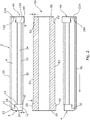
- FIG. 2 in which a sectional elevation of an assembled sleeve 8 with end ring 4 screwingly disposed in the formerly open end 6 is illustrated, the various layers 30, 32, 34 are provided inside the tube 8 such that their annular radial end surfaces (visible in Figure 1 ) are substantially co-planar with the annular radial surface of shoulder 14. Additionally in this Figure, a further coating layer 36 is shown having been chemically or mechanically applied or affixed to the exterior axial cylindrical surface of the tube 8.
- the coating will be a Chromium Oxide coating as is known in the art, and will be thermally or chemically applied after theend rings are securely fixed to either end of the tube 6 so that a portion of said coating layer covers the axial end surfaces of the flange portion 22 (22A for end ring 4A at the opposite end of the tube 8 from end ring 4) and thus covers the seam formed between the flange portions 22, 22Aand the respective radial surfaces 10 (10A) of the tube 8 with which they mate.
- the coating may be replaced by, or may be provided on, a cylindrical printing plate mechanically affixed around said exterior surface of the tube 8, but in either case it is preferred that the said seam is covered, for reasons specifically described below.
- One further feature not specifically illustrated is the possible provision of one or more O-ring seals provided at one or more positionsalong the seam formed between theend ring flange (or bodyportion(s)) and the corresponding adjacent surface of the tube radial end surface 10 (or the axial engagement surfaces formed bythe rebate).
- O-ring seals provided at one or more positionsalong the seam formed between theend ring flange (or bodyportion(s)) and the corresponding adjacent surface of the tube radial end surface 10 (or the axial engagement surfaces formed bythe rebate).
- the internal diametral dimensions of one (or both) of the end rings 4 (4A) are carefully chosen so as to leave an exposed internal annular shoulder 40, most preferably being (radially) only a portion of the innermost layer 30, but in other embodiments, the shoulder40 may be defined entirely bythe innermost layer 30, or it may be defined bythe in nermost layer 30 and a part of the layer 32. Regardless of how and by which particular layer said shoulder might be defined, its purpose is to render the sleeve 2 'handed' as regards a mandrel 50 over which it is adapted to be slid, and to which it is ultimately secured, most preferably by interference fit as previously mentioned.
- Figure 2 is schematic in that it shows the sleeve 2 exploded for clarity, in practice, the innermost axial surface of the innermost layer 30 mates with an exterior cylindrical surface 52 of said mandrel, and most preferably the far end 54 of mandrel 50 (being that end which is effectively inaccessible to an operative wishing to extract either sleeve or mandrel from the print machinery in which they are mounted) is further provided with a collar 56 which is axially the same length as the end ring 4 and of the same height as the radial thickness of shoulder 40 so that the sleeve can only be completely slid over the mandrel and properlydisposed thereon only if the sleeve is correctly orientated, that is with the end in which end ring 4 is disposed being fed over the mandrel first.
- end ring 4A At the alternate end of the mandrel, where end ring 4A is provided, a similar arrangement is also provided, though in this case the innermost diametral dimension of the end ring is less than the innermost diametral dimension of the innermost layer 30 so that an internal shoulder 60 is defined by the axially innermost radial surface of the shank portion 12A of that end ring.
- a free end 58 of the mandrel 50 is shown rebated around its exterior surface so as to provide a corresponding shoulder 62 which comes into abutting mating relation with the shoulder 60, such only being capable of being achieved when the sleeve is attempted to be fitted to the mandrel in the correct orientation.
- end rings 4, 4A having openings of slightly different diameters
- the mandrel itself having collar 56 and a rebate provided around its front end 58
- different portions of the sleeve provide different clearanced fits around corresponding different portions of the mandrel.
- FIG.2 A yet further preferred feature is illustrated in Figure2 , particularly as regards the seam formed between the flange portions 22, 22A of the end rings, and the outermost radial end surfaces 10, 10A of the tube which forms the mandrel.
- the outermost edges of the flange portions 22 are preferably chamfered off in a mannerwhich results in anyone or more of the following:
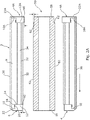
- FIG. 2A an alternative embodiment is illustrated in which the mandrel 50 is provided only with a rebate around its free end 58 (i.e. without collar 56 as illustrated in Figure 2 ) so as to define only a single shoulder 62 which comes into abutting mating relationship with the shoulder 60 defined in the end ring 4A, provided of course that the sleeve 2 is in the orientation shown in the Figure.
- the sleeve orientation were reverse, then it would be impossible to slide the sleeve over the mandrel beyond the shoulder 62 because the interior diameter of the end ring 4A is less than that of the cylindrical surface 52 of said mandrel.
- the sleeve 2 may still be provided with an exposed shoulder 40 of layer 30, and in certain embodiments, the collar 56 provided on the far end 54 of the mandrel ( Figure 2 ) may be replaced with an annular gasket or O-ring seal (notshown) of a thickness which both permits the innermost axial surface of end ring 4 to slide thereover, and additionally provides a seal therewith to prevent fluid ingress into the otherwise exposed radial surface of layer 30, i.e. the shoulder 40.
- one reason for retaining the exposed shoulder 40 is to provide a means for operatives to quickly identify which end of the sleeve is which, and thus correctly orientate the sleeve prior to any attempt to slide the sleeve over the mandrel.
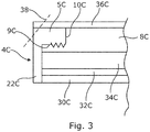
- the end rings 4C may be secured to and within the radial end surface 10C of tubular sleeve 8C.
- the rebate is provided in and around the exterior axial surface of the tube 8C, and the end ring 4C takes the form of a cap which is screwed onto the tube 8C by means of corresponding threads provided in both an axial inner surface of an end ring web portion 5C and an axial outer surface 9C in an end region of said tube.
- end ring 4C is provided with a radially inwardly extending flange portion 22C which is shown in mating relation with the otherwise exposed radial end surfaces of inner layers 30C, 32C, 34C so as to effectively cover them and thus prevent ingress of liquid therein.
- Coating layer 36C is again applied after connecting the end ring 4C to the tube 8C, again effectively concealing the radial seam defined between the end ring and the outermost radial end surface 10C of the tube 8C.
- Dotted line 38 provides an indication of how the sleeve may be chamfered, as previouslydescribed.
- a substantially tubular interchangeable sleeve adapted for applying a printing or coating liquid to a substrate material or offset roller.
- the sleeve has a multi-layer construction primarily consisting of a first outer layer of a dimensionallystable substantially fluid-impregnable solid material, such as aluminium or steel, around the exterior surface of which is affixed or applied a printing ink or coating liquid receiving plate or layer.
- the sleeve further comprises one or more further interior layers of relatively less dimensionally stable, compressible usuallyfibrous materials disposed inwardly of the interior surface of thefirst layer which, under air pressure, can be compressed so as to enlarge the inner dimensions of the sleeve so that it can be slid over a suitable bridge mandrel.
- the sleeve further comprises at least one end ring of a dimensionally stable substantially fluid-impregnable solid material.
- the end ring comprises first and second body portions, one being disposed radially to the outside of the other, so that when one of said body portions is received within a rebate provided in a radial end surface of the first outer layer and mechanically connected therein by means of mating engagement of screw threads provided on a substantially axially aligned surface of the end ring body portion and a correspondingly aligned surface of the rebate, the alternate end ring body portion partially or completely overlies one or more of the radial end surfaces of interior layers so as to prevent fluid ingress into that or those layers.
Landscapes
- Printing Plates And Materials Therefor (AREA)
Claims (14)
- Manchon sensiblement tubulaire (2) présentant un axe longitudinal adapté pour appliquer un liquide d'impression ou de revêtement sur un matériau de substrat ou un rouleau décalé, ledit manchon présentant une construction multicouche constituée d'une première couche externe (8) constituée d'un matériau solide indéformable sensiblement apte à être imprégné par un fluide autour d'une surface extérieure sur laquelle est fixée ou appliquée une plaque ou couche (36) recevant le liquide d'impression ou de revêtement, et au moins une seconde couche (30, 32, 34) d'un matériau compressible relativement moins indéformable, disposé vers l'intérieur d'une surface intérieure de la première couche et faisant interface avec celle-ci, ledit manchon comprenant en outre au moins une bague d'extrémité (4) d'un matériau solide indéformable sensiblement apte à être imprégné par un fluide, ladite bague d'extrémité comprenant des première et seconde parties de corps, ladite première partie de corps étant disposée radialement à l'extérieur de la seconde partie de corps et étant reçue dans une feuillure prévue dans une surface radiale d'extrémité (10) de ladite première couche extérieure,
caractérisé en ce que
ladite bague d'extrémité est solidement reliée mécaniquement à ladite feuillure au moyen de filetages correspondants (18, 20) prévus à la fois sur une surface alignée axialement (20) de ladite première partie de corps de bague d'extrémité et sur une surface alignée axialement (16) de ladite feuillure, et une couche de joint d'étanchéité est prévue sur une surface d'extrémité de la seconde couche, ladite couche de joint d'étanchéité étant l'un des suivants : un joint d'étanchéité annulaire, et un composé de joint d'étanchéité initialement liquide et finalement durcissable, de sorte que lorsque les parties filetées respectives sont complètement assujetties et la bague d'extrémité est complètement fixée au manchon, ladite seconde partie de corps de bague d'extrémité comprime légèrement ladite couche de joint d'étanchéité et recouvre sensiblement une surface d'extrémité de la seconde couche interne de manière à empêcher l'entrée de fluide dans le matériau compressible à travers ladite surface d'extrémité de ladite seconde couche. - Manchon (2) selon la revendication 1, dans lequel la feuillure dans la première couche (8) est prévue le long et autour d'un bord circonférentiel intérieur de celle-ci de sorte que la surface de contact axial (16) fournie par de telles feuillures soit dirigée radialement vers l'intérieur de ladite première couche.
- Manchon (2) selon la revendication 2, dans lequel les filetages (18, 20) sont prévus sur une région axialement la plus interne de la surface alignée axialement (12) de ladite première partie de corps de la bague d'extrémité (4) et une région axialement la plus interne de la surface alignée axialement (16) de ladite feuillure.
- Manchon (2) selon la revendication 2 ou 3, dans lequel la première partie de corps de la bague d'extrémité (4) est munie d'une partie bride (22) qui s'étend radialement vers l'extérieur depuis la première partie de corps de manière à recouvrir sensiblement la surface d'extrémité radiale restante (10) de la première couche (8) disposée radialement à l'extérieur de la feuillure dans celle-ci.
- Manchon (2) selon la revendication 4, dans lequel un ou plusieurs joints toriques sont prévus dans le joint créé entre la partie bride (22) de la bague d'extrémité (4) et une surface d'extrémité radiale correspondante (10) du manchon.
- Manchon (2) selon la revendication 4 ou 5, dans lequel la couche (36) recevant le liquide d'impression ou de revêtement est appliquée sur le manchon après que la bague d'extrémité (4) soit complètement fixée à la première couche (8) dudit manchon, de sorte que ladite couche réceptrice de liquide d'impression ou de revêtement recouvre efficacement tout joint circonférentiel formé entre celles-ci.
- Manchon (2) selon l'une quelconque des revendications précédentes, dans lequel le corps de la seconde partie de corps de la bague d'extrémité (4) qui recouvre sensiblement la surface d'extrémité radiale de la seconde couche (30, 32, 34) le fait de manière à recouvrir complètement ladite surface radiale de la seconde couche.
- Manchon (2) selon l'une quelconque des revendications précédentes, dans lequel les bords radialement les plus à l'extérieur des extrémités du manchon sont chanfreinés.
- Manchon (2) selon la revendication 8, dans lequel la surface de chanfrein est définie partiellement ou complètement par l'un ou plusieurs des éléments suivants- la première couche (8),- la couche de réception de liquide d'impression ou de revêtement (36),- la bague d'extrémité (4).
- Manchon (2) selon l'une quelconque des revendications précédentes, dans lequel le manchon comprend deux bagues d'extrémité (4), une à chacune de ses extrémités.
- Manchon (2) selon l'une quelconque des revendications précédentes, dans lequel un ou plusieurs joints toriques sont prévus entre la surface la plus externe alignée axialement (20) de la première partie de corps de la bague d'extrémité et la surface alignée axialement (16) de la feuillure.
- Manchon (2) selon l'une quelconque des revendications précédentes, dans lequel une surface axiale la plus à l'intérieur de la bague d'extrémité (4) est dimensionnée de sorte qu'elle soit disposée de l'une des manières suivantes : radialement vers l'extérieur et radialement vers l'intérieur, de la surface la plus à l'intérieur de la seconde couche (30, 32, 34) de sorte qu'un épaulement (40, 60) soit défini dans la surface cylindrique intérieure du manchon, respectivement par une surface radiale annulaire exposée de la deuxième couche ou par une surface radiale annulaire exposée de la bague d'extrémité.
- Manchon (2) selon l'une quelconque des revendications précédentes, constitué des couches sensiblement tubulaires suivantes, dans l'ordre croissant radialement :- une couche d'enveloppe de base (30) en fibre de verre- une couche compressible (32) constituée de l'un parmi : un polymère, une composition expansée et / ou cellulaire,- une couche d'accumulation composite (34),- une couche métallique (8) sensiblement indéformable apte à être imprégnée par un fluide, constituée d'aluminium, d'acier, d'aluminium anodisé et d'acier anodisé, et- une couche de revêtement (36) constituée de l'un des éléments suivants : Oxyde de Chrome et une céramique.
- Ensemble comprenant un manchon (2) selon la revendication 12 et l'une quelconque des revendications qui en dépend, associé à un mandrin (50) pourvu d'un épaulement correspondant (56, 58, 62) prévu dans sa surface extérieure sensiblement cylindrique (52) et avec lequel l'épaulement (40, 60) du manchon vient en butée pour empêcher la poursuite du déplacement axial du manchon par rapport au mandrin.
Applications Claiming Priority (2)
| Application Number | Priority Date | Filing Date | Title |
|---|---|---|---|
| GB1520915.8A GB2544785A (en) | 2015-11-26 | 2015-11-26 | A sleeve for a bridge mandrel, and a bridge mandrel and sleeve assembly |
| PCT/EP2016/077989 WO2017089221A1 (fr) | 2015-11-26 | 2016-11-17 | Manchon pour mandrin en pont, et mandrin en pont et ensemble manchon |
Publications (2)
| Publication Number | Publication Date |
|---|---|
| EP3368317A1 EP3368317A1 (fr) | 2018-09-05 |
| EP3368317B1 true EP3368317B1 (fr) | 2019-06-12 |
Family
ID=55177310
Family Applications (1)
| Application Number | Title | Priority Date | Filing Date |
|---|---|---|---|
| EP16798694.2A Active EP3368317B1 (fr) | 2015-11-26 | 2016-11-17 | Manchon pour mandrin en pont, et mandrin en pont et ensemble manchon |
Country Status (4)
| Country | Link |
|---|---|
| US (1) | US11059284B2 (fr) |
| EP (1) | EP3368317B1 (fr) |
| GB (1) | GB2544785A (fr) |
| WO (1) | WO2017089221A1 (fr) |
Families Citing this family (8)
| Publication number | Priority date | Publication date | Assignee | Title |
|---|---|---|---|---|
| CN108081751A (zh) * | 2017-12-08 | 2018-05-29 | 广州市佳盛印刷有限公司 | 一种烟草包装盒印刷装置的安装结构 |
| ES2919561T3 (es) | 2019-02-20 | 2022-07-27 | Flint Group Germany Gmbh | Cilindro de baja vibración |
| GB201907494D0 (en) | 2019-05-28 | 2019-07-10 | Sandon Global Engraving Tech Limited | A compressible liner a method of manufacture thereof and a sleeve assembly utilising such a liner |
| CN110216976A (zh) * | 2019-07-16 | 2019-09-10 | 深圳市兴博防伪技术开发有限公司 | 一种胶辊 |
| GB201915458D0 (en) | 2019-10-24 | 2019-12-11 | Sandon Global Engraving Tech Limited | Lightweight interchangeable magnetic sleeve and method of manufacture thereof |
| CN110848389B (zh) * | 2019-10-25 | 2024-06-14 | 海天塑机集团有限公司 | 一种强酸或者强碱环境中的旋转密封结构 |
| GB202115642D0 (en) | 2021-11-01 | 2021-12-15 | Sandon Global Engraving Tech Limited | An end ring for a sleeve, a sleeve adapted to receive such an end ring, and a sleeve assembly incorporating such and end ring |
| CN116493627A (zh) * | 2023-04-24 | 2023-07-28 | 西安航天发动机有限公司 | 一种火箭发动机薄壁内筒圆加工工艺装备及其使用方法 |
Family Cites Families (9)
| Publication number | Priority date | Publication date | Assignee | Title |
|---|---|---|---|---|
| US4383483A (en) | 1980-10-06 | 1983-05-17 | Mosstype Corporation | Hydraulically-actuated mandrel for a demountable printing cylinder |
| US4386566A (en) | 1980-10-06 | 1983-06-07 | Mosstype Corporation | Mandrel assembly for demountable printing cylinder |
| US4503769A (en) | 1982-06-21 | 1985-03-12 | Armotek Industries, Inc. | Metal coated thin wall plastic printing cylinder for rotogravure printing |
| US4651643A (en) | 1985-02-14 | 1987-03-24 | Sidney Katz | Adaptors for use with printing cylinder mandrels |
| JPS6219457A (ja) | 1985-07-19 | 1987-01-28 | Showa Alum Corp | グラビア印刷用製版ロ−ル |
| ES2022212B3 (es) * | 1987-06-19 | 1991-12-01 | Saueressig Gmbh + Co | Cilindro de huecograbado consistiendo en un nucleo y un manguito soltable unido con dicho nucleo |
| US5840386A (en) * | 1996-02-22 | 1998-11-24 | Praxair S.T. Technology, Inc. | Sleeve for a liquid transfer roll and method for producing it |
| US6276271B1 (en) | 2000-03-17 | 2001-08-21 | Day International, Inc. | Bridge mandrel for flexographic printing systems |
| DE202008002329U1 (de) * | 2008-02-20 | 2009-06-25 | Spilker Gmbh | Auswechselbare Druckwalze |
-
2015
- 2015-11-26 GB GB1520915.8A patent/GB2544785A/en not_active Withdrawn
-
2016
- 2016-11-17 EP EP16798694.2A patent/EP3368317B1/fr active Active
- 2016-11-17 WO PCT/EP2016/077989 patent/WO2017089221A1/fr not_active Ceased
- 2016-11-17 US US15/778,798 patent/US11059284B2/en active Active
Non-Patent Citations (1)
| Title |
|---|
| None * |
Also Published As
| Publication number | Publication date |
|---|---|
| WO2017089221A1 (fr) | 2017-06-01 |
| US11059284B2 (en) | 2021-07-13 |
| GB201520915D0 (en) | 2016-01-13 |
| GB2544785A (en) | 2017-05-31 |
| US20180345656A1 (en) | 2018-12-06 |
| EP3368317A1 (fr) | 2018-09-05 |
Similar Documents
| Publication | Publication Date | Title |
|---|---|---|
| EP3368317B1 (fr) | Manchon pour mandrin en pont, et mandrin en pont et ensemble manchon | |
| AU770336B2 (en) | Bridge mandrel for flexographic printing systems | |
| US6360662B1 (en) | Bridge mandrel for flexographic printing systems | |
| US5904095A (en) | Bridge mandrel for flexographic printing presses | |
| US5507228A (en) | Printing cylinder | |
| EP2463112B1 (fr) | Manchons et segments de manchons pour flexographie | |
| US9409385B2 (en) | Intermediate sleeve | |
| AU2020371883A1 (en) | Lightweight interchangeable magnetic sleeve and method of manufacture thereof | |
| CN112537119B (zh) | 用于印刷设备的芯棒、印刷滚筒、印刷设备 | |
| US20250296797A1 (en) | Primer apparatus | |
| EP3261844B1 (fr) | Rouleau d'une machine d'impression flexographique et machine d'impression flexographique | |
| US20030205155A1 (en) | Thin-walled bridge mandrel | |
| JP2007044987A (ja) | 缶の印刷装置及び版の取付方法 | |
| JP2006272682A (ja) | 缶の印刷装置 | |
| JP2009226648A (ja) | 印刷版胴、缶の印刷装置及び印刷版胴の形成方法 | |
| JP2008273209A (ja) | 印刷機胴 | |
| EP2703181A2 (fr) | Manchon pour cylindre anilox et procédé de fabrication de manchons de cylindres anilox | |
| US20060021530A1 (en) | Apparatus and method of enhancing printing press cylinders | |
| EP3162563B1 (fr) | Cylindre porte-plaque et dispositif de montage de plaque | |
| JP2010173315A (ja) | スリーブ印刷版用版胴、缶の印刷装置及び缶の印刷方法 | |
| EP4698333A1 (fr) | Manchon applicateur de liquide et ensemble applicateur comprenant un tel manchon | |
| WO1997025209A1 (fr) | Cylindre d'impression avec manchon amovible | |
| JP5485206B2 (ja) | 缶の印刷装置及びスリーブ | |
| US20070006753A1 (en) | Web-fed rotary press having sleeve-shaped printing blankets | |
| WO1997025208A1 (fr) | Mandrin de cylindre d'impression pour manchons servant de forme d'impression |
Legal Events
| Date | Code | Title | Description |
|---|---|---|---|
| STAA | Information on the status of an ep patent application or granted ep patent |
Free format text: STATUS: UNKNOWN |
|
| STAA | Information on the status of an ep patent application or granted ep patent |
Free format text: STATUS: THE INTERNATIONAL PUBLICATION HAS BEEN MADE |
|
| PUAI | Public reference made under article 153(3) epc to a published international application that has entered the european phase |
Free format text: ORIGINAL CODE: 0009012 |
|
| STAA | Information on the status of an ep patent application or granted ep patent |
Free format text: STATUS: REQUEST FOR EXAMINATION WAS MADE |
|
| 17P | Request for examination filed |
Effective date: 20180521 |
|
| AK | Designated contracting states |
Kind code of ref document: A1 Designated state(s): AL AT BE BG CH CY CZ DE DK EE ES FI FR GB GR HR HU IE IS IT LI LT LU LV MC MK MT NL NO PL PT RO RS SE SI SK SM TR |
|
| AX | Request for extension of the european patent |
Extension state: BA ME |
|
| STAA | Information on the status of an ep patent application or granted ep patent |
Free format text: STATUS: EXAMINATION IS IN PROGRESS |
|
| 17Q | First examination report despatched |
Effective date: 20180913 |
|
| DAV | Request for validation of the european patent (deleted) | ||
| DAX | Request for extension of the european patent (deleted) | ||
| GRAP | Despatch of communication of intention to grant a patent |
Free format text: ORIGINAL CODE: EPIDOSNIGR1 |
|
| STAA | Information on the status of an ep patent application or granted ep patent |
Free format text: STATUS: GRANT OF PATENT IS INTENDED |
|
| INTG | Intention to grant announced |
Effective date: 20190327 |
|
| GRAS | Grant fee paid |
Free format text: ORIGINAL CODE: EPIDOSNIGR3 |
|
| GRAA | (expected) grant |
Free format text: ORIGINAL CODE: 0009210 |
|
| STAA | Information on the status of an ep patent application or granted ep patent |
Free format text: STATUS: THE PATENT HAS BEEN GRANTED |
|
| AK | Designated contracting states |
Kind code of ref document: B1 Designated state(s): AL AT BE BG CH CY CZ DE DK EE ES FI FR GB GR HR HU IE IS IT LI LT LU LV MC MK MT NL NO PL PT RO RS SE SI SK SM TR |
|
| REG | Reference to a national code |
Ref country code: GB Ref legal event code: FG4D |
|
| REG | Reference to a national code |
Ref country code: CH Ref legal event code: EP |
|
| REG | Reference to a national code |
Ref country code: AT Ref legal event code: REF Ref document number: 1142058 Country of ref document: AT Kind code of ref document: T Effective date: 20190615 |
|
| REG | Reference to a national code |
Ref country code: DE Ref legal event code: R096 Ref document number: 602016015330 Country of ref document: DE |
|
| REG | Reference to a national code |
Ref country code: IE Ref legal event code: FG4D |
|
| REG | Reference to a national code |
Ref country code: NL Ref legal event code: FP |
|
| REG | Reference to a national code |
Ref country code: LT Ref legal event code: MG4D |
|
| PG25 | Lapsed in a contracting state [announced via postgrant information from national office to epo] |
Ref country code: FI Free format text: LAPSE BECAUSE OF FAILURE TO SUBMIT A TRANSLATION OF THE DESCRIPTION OR TO PAY THE FEE WITHIN THE PRESCRIBED TIME-LIMIT Effective date: 20190612 Ref country code: LT Free format text: LAPSE BECAUSE OF FAILURE TO SUBMIT A TRANSLATION OF THE DESCRIPTION OR TO PAY THE FEE WITHIN THE PRESCRIBED TIME-LIMIT Effective date: 20190612 Ref country code: AL Free format text: LAPSE BECAUSE OF FAILURE TO SUBMIT A TRANSLATION OF THE DESCRIPTION OR TO PAY THE FEE WITHIN THE PRESCRIBED TIME-LIMIT Effective date: 20190612 Ref country code: SE Free format text: LAPSE BECAUSE OF FAILURE TO SUBMIT A TRANSLATION OF THE DESCRIPTION OR TO PAY THE FEE WITHIN THE PRESCRIBED TIME-LIMIT Effective date: 20190612 Ref country code: HR Free format text: LAPSE BECAUSE OF FAILURE TO SUBMIT A TRANSLATION OF THE DESCRIPTION OR TO PAY THE FEE WITHIN THE PRESCRIBED TIME-LIMIT Effective date: 20190612 Ref country code: NO Free format text: LAPSE BECAUSE OF FAILURE TO SUBMIT A TRANSLATION OF THE DESCRIPTION OR TO PAY THE FEE WITHIN THE PRESCRIBED TIME-LIMIT Effective date: 20190912 |
|
| PG25 | Lapsed in a contracting state [announced via postgrant information from national office to epo] |
Ref country code: GR Free format text: LAPSE BECAUSE OF FAILURE TO SUBMIT A TRANSLATION OF THE DESCRIPTION OR TO PAY THE FEE WITHIN THE PRESCRIBED TIME-LIMIT Effective date: 20190913 Ref country code: RS Free format text: LAPSE BECAUSE OF FAILURE TO SUBMIT A TRANSLATION OF THE DESCRIPTION OR TO PAY THE FEE WITHIN THE PRESCRIBED TIME-LIMIT Effective date: 20190612 Ref country code: LV Free format text: LAPSE BECAUSE OF FAILURE TO SUBMIT A TRANSLATION OF THE DESCRIPTION OR TO PAY THE FEE WITHIN THE PRESCRIBED TIME-LIMIT Effective date: 20190612 Ref country code: BG Free format text: LAPSE BECAUSE OF FAILURE TO SUBMIT A TRANSLATION OF THE DESCRIPTION OR TO PAY THE FEE WITHIN THE PRESCRIBED TIME-LIMIT Effective date: 20190912 |
|
| REG | Reference to a national code |
Ref country code: AT Ref legal event code: MK05 Ref document number: 1142058 Country of ref document: AT Kind code of ref document: T Effective date: 20190612 |
|
| PG25 | Lapsed in a contracting state [announced via postgrant information from national office to epo] |
Ref country code: SK Free format text: LAPSE BECAUSE OF FAILURE TO SUBMIT A TRANSLATION OF THE DESCRIPTION OR TO PAY THE FEE WITHIN THE PRESCRIBED TIME-LIMIT Effective date: 20190612 Ref country code: EE Free format text: LAPSE BECAUSE OF FAILURE TO SUBMIT A TRANSLATION OF THE DESCRIPTION OR TO PAY THE FEE WITHIN THE PRESCRIBED TIME-LIMIT Effective date: 20190612 Ref country code: CZ Free format text: LAPSE BECAUSE OF FAILURE TO SUBMIT A TRANSLATION OF THE DESCRIPTION OR TO PAY THE FEE WITHIN THE PRESCRIBED TIME-LIMIT Effective date: 20190612 Ref country code: RO Free format text: LAPSE BECAUSE OF FAILURE TO SUBMIT A TRANSLATION OF THE DESCRIPTION OR TO PAY THE FEE WITHIN THE PRESCRIBED TIME-LIMIT Effective date: 20190612 Ref country code: PT Free format text: LAPSE BECAUSE OF FAILURE TO SUBMIT A TRANSLATION OF THE DESCRIPTION OR TO PAY THE FEE WITHIN THE PRESCRIBED TIME-LIMIT Effective date: 20191014 Ref country code: AT Free format text: LAPSE BECAUSE OF FAILURE TO SUBMIT A TRANSLATION OF THE DESCRIPTION OR TO PAY THE FEE WITHIN THE PRESCRIBED TIME-LIMIT Effective date: 20190612 |
|
| PG25 | Lapsed in a contracting state [announced via postgrant information from national office to epo] |
Ref country code: SM Free format text: LAPSE BECAUSE OF FAILURE TO SUBMIT A TRANSLATION OF THE DESCRIPTION OR TO PAY THE FEE WITHIN THE PRESCRIBED TIME-LIMIT Effective date: 20190612 Ref country code: IS Free format text: LAPSE BECAUSE OF FAILURE TO SUBMIT A TRANSLATION OF THE DESCRIPTION OR TO PAY THE FEE WITHIN THE PRESCRIBED TIME-LIMIT Effective date: 20191012 Ref country code: ES Free format text: LAPSE BECAUSE OF FAILURE TO SUBMIT A TRANSLATION OF THE DESCRIPTION OR TO PAY THE FEE WITHIN THE PRESCRIBED TIME-LIMIT Effective date: 20190612 |
|
| REG | Reference to a national code |
Ref country code: DE Ref legal event code: R097 Ref document number: 602016015330 Country of ref document: DE |
|
| PG25 | Lapsed in a contracting state [announced via postgrant information from national office to epo] |
Ref country code: TR Free format text: LAPSE BECAUSE OF FAILURE TO SUBMIT A TRANSLATION OF THE DESCRIPTION OR TO PAY THE FEE WITHIN THE PRESCRIBED TIME-LIMIT Effective date: 20190612 |
|
| PLBE | No opposition filed within time limit |
Free format text: ORIGINAL CODE: 0009261 |
|
| STAA | Information on the status of an ep patent application or granted ep patent |
Free format text: STATUS: NO OPPOSITION FILED WITHIN TIME LIMIT |
|
| PG25 | Lapsed in a contracting state [announced via postgrant information from national office to epo] |
Ref country code: PL Free format text: LAPSE BECAUSE OF FAILURE TO SUBMIT A TRANSLATION OF THE DESCRIPTION OR TO PAY THE FEE WITHIN THE PRESCRIBED TIME-LIMIT Effective date: 20190612 Ref country code: DK Free format text: LAPSE BECAUSE OF FAILURE TO SUBMIT A TRANSLATION OF THE DESCRIPTION OR TO PAY THE FEE WITHIN THE PRESCRIBED TIME-LIMIT Effective date: 20190612 |
|
| 26N | No opposition filed |
Effective date: 20200313 |
|
| PG25 | Lapsed in a contracting state [announced via postgrant information from national office to epo] |
Ref country code: IS Free format text: LAPSE BECAUSE OF FAILURE TO SUBMIT A TRANSLATION OF THE DESCRIPTION OR TO PAY THE FEE WITHIN THE PRESCRIBED TIME-LIMIT Effective date: 20200224 |
|
| REG | Reference to a national code |
Ref country code: CH Ref legal event code: PL |
|
| PG2D | Information on lapse in contracting state deleted |
Ref country code: IS |
|
| PG25 | Lapsed in a contracting state [announced via postgrant information from national office to epo] |
Ref country code: CH Free format text: LAPSE BECAUSE OF NON-PAYMENT OF DUE FEES Effective date: 20191130 Ref country code: LU Free format text: LAPSE BECAUSE OF NON-PAYMENT OF DUE FEES Effective date: 20191117 Ref country code: MC Free format text: LAPSE BECAUSE OF FAILURE TO SUBMIT A TRANSLATION OF THE DESCRIPTION OR TO PAY THE FEE WITHIN THE PRESCRIBED TIME-LIMIT Effective date: 20190612 Ref country code: LI Free format text: LAPSE BECAUSE OF NON-PAYMENT OF DUE FEES Effective date: 20191130 |
|
| REG | Reference to a national code |
Ref country code: BE Ref legal event code: MM Effective date: 20191130 |
|
| PG25 | Lapsed in a contracting state [announced via postgrant information from national office to epo] |
Ref country code: IE Free format text: LAPSE BECAUSE OF NON-PAYMENT OF DUE FEES Effective date: 20191117 |
|
| PG25 | Lapsed in a contracting state [announced via postgrant information from national office to epo] |
Ref country code: BE Free format text: LAPSE BECAUSE OF NON-PAYMENT OF DUE FEES Effective date: 20191130 |
|
| PG25 | Lapsed in a contracting state [announced via postgrant information from national office to epo] |
Ref country code: CY Free format text: LAPSE BECAUSE OF FAILURE TO SUBMIT A TRANSLATION OF THE DESCRIPTION OR TO PAY THE FEE WITHIN THE PRESCRIBED TIME-LIMIT Effective date: 20190612 |
|
| PG25 | Lapsed in a contracting state [announced via postgrant information from national office to epo] |
Ref country code: HU Free format text: LAPSE BECAUSE OF FAILURE TO SUBMIT A TRANSLATION OF THE DESCRIPTION OR TO PAY THE FEE WITHIN THE PRESCRIBED TIME-LIMIT; INVALID AB INITIO Effective date: 20161117 Ref country code: MT Free format text: LAPSE BECAUSE OF FAILURE TO SUBMIT A TRANSLATION OF THE DESCRIPTION OR TO PAY THE FEE WITHIN THE PRESCRIBED TIME-LIMIT Effective date: 20190612 |
|
| PG25 | Lapsed in a contracting state [announced via postgrant information from national office to epo] |
Ref country code: SI Free format text: LAPSE BECAUSE OF FAILURE TO SUBMIT A TRANSLATION OF THE DESCRIPTION OR TO PAY THE FEE WITHIN THE PRESCRIBED TIME-LIMIT Effective date: 20190612 |
|
| PG25 | Lapsed in a contracting state [announced via postgrant information from national office to epo] |
Ref country code: MK Free format text: LAPSE BECAUSE OF FAILURE TO SUBMIT A TRANSLATION OF THE DESCRIPTION OR TO PAY THE FEE WITHIN THE PRESCRIBED TIME-LIMIT Effective date: 20190612 |
|
| PGFP | Annual fee paid to national office [announced via postgrant information from national office to epo] |
Ref country code: NL Payment date: 20251113 Year of fee payment: 10 |
|
| PGFP | Annual fee paid to national office [announced via postgrant information from national office to epo] |
Ref country code: DE Payment date: 20251111 Year of fee payment: 10 |
|
| PGFP | Annual fee paid to national office [announced via postgrant information from national office to epo] |
Ref country code: GB Payment date: 20251110 Year of fee payment: 10 |
|
| PGFP | Annual fee paid to national office [announced via postgrant information from national office to epo] |
Ref country code: IT Payment date: 20251111 Year of fee payment: 10 |
|
| PGFP | Annual fee paid to national office [announced via postgrant information from national office to epo] |
Ref country code: FR Payment date: 20251110 Year of fee payment: 10 |