EP3368332B1 - Synthesis of superposition shape images by light interacting with superposed layers of lenslet gratings - Google Patents
Synthesis of superposition shape images by light interacting with superposed layers of lenslet gratings Download PDFInfo
- Publication number
- EP3368332B1 EP3368332B1 EP16736224.3A EP16736224A EP3368332B1 EP 3368332 B1 EP3368332 B1 EP 3368332B1 EP 16736224 A EP16736224 A EP 16736224A EP 3368332 B1 EP3368332 B1 EP 3368332B1
- Authority
- EP
- European Patent Office
- Prior art keywords
- base layer
- revealing
- lenslet
- layer
- gratings
- Prior art date
- Legal status (The legal status is an assumption and is not a legal conclusion. Google has not performed a legal analysis and makes no representation as to the accuracy of the status listed.)
- Active
Links
Images


Classifications
-
- B—PERFORMING OPERATIONS; TRANSPORTING
- B42—BOOKBINDING; ALBUMS; FILES; SPECIAL PRINTED MATTER
- B42D—BOOKS; BOOK COVERS; LOOSE LEAVES; PRINTED MATTER CHARACTERISED BY IDENTIFICATION OR SECURITY FEATURES; PRINTED MATTER OF SPECIAL FORMAT OR STYLE NOT OTHERWISE PROVIDED FOR; DEVICES FOR USE THEREWITH AND NOT OTHERWISE PROVIDED FOR; MOVABLE-STRIP WRITING OR READING APPARATUS
- B42D25/00—Information-bearing cards or sheet-like structures characterised by identification or security features; Manufacture thereof
- B42D25/30—Identification or security features, e.g. for preventing forgery
- B42D25/324—Reliefs
-
- B—PERFORMING OPERATIONS; TRANSPORTING
- B42—BOOKBINDING; ALBUMS; FILES; SPECIAL PRINTED MATTER
- B42D—BOOKS; BOOK COVERS; LOOSE LEAVES; PRINTED MATTER CHARACTERISED BY IDENTIFICATION OR SECURITY FEATURES; PRINTED MATTER OF SPECIAL FORMAT OR STYLE NOT OTHERWISE PROVIDED FOR; DEVICES FOR USE THEREWITH AND NOT OTHERWISE PROVIDED FOR; MOVABLE-STRIP WRITING OR READING APPARATUS
- B42D25/00—Information-bearing cards or sheet-like structures characterised by identification or security features; Manufacture thereof
- B42D25/30—Identification or security features, e.g. for preventing forgery
- B42D25/351—Translucent or partly translucent parts, e.g. windows
-
- B—PERFORMING OPERATIONS; TRANSPORTING
- B42—BOOKBINDING; ALBUMS; FILES; SPECIAL PRINTED MATTER
- B42D—BOOKS; BOOK COVERS; LOOSE LEAVES; PRINTED MATTER CHARACTERISED BY IDENTIFICATION OR SECURITY FEATURES; PRINTED MATTER OF SPECIAL FORMAT OR STYLE NOT OTHERWISE PROVIDED FOR; DEVICES FOR USE THEREWITH AND NOT OTHERWISE PROVIDED FOR; MOVABLE-STRIP WRITING OR READING APPARATUS
- B42D25/00—Information-bearing cards or sheet-like structures characterised by identification or security features; Manufacture thereof
- B42D25/20—Information-bearing cards or sheet-like structures characterised by identification or security features; Manufacture thereof characterised by a particular use or purpose
- B42D25/23—Identity cards
-
- B—PERFORMING OPERATIONS; TRANSPORTING
- B42—BOOKBINDING; ALBUMS; FILES; SPECIAL PRINTED MATTER
- B42D—BOOKS; BOOK COVERS; LOOSE LEAVES; PRINTED MATTER CHARACTERISED BY IDENTIFICATION OR SECURITY FEATURES; PRINTED MATTER OF SPECIAL FORMAT OR STYLE NOT OTHERWISE PROVIDED FOR; DEVICES FOR USE THEREWITH AND NOT OTHERWISE PROVIDED FOR; MOVABLE-STRIP WRITING OR READING APPARATUS
- B42D25/00—Information-bearing cards or sheet-like structures characterised by identification or security features; Manufacture thereof
- B42D25/20—Information-bearing cards or sheet-like structures characterised by identification or security features; Manufacture thereof characterised by a particular use or purpose
- B42D25/28—Information-bearing cards or sheet-like structures characterised by identification or security features; Manufacture thereof characterised by a particular use or purpose for use in medical treatment or therapy
-
- B—PERFORMING OPERATIONS; TRANSPORTING
- B42—BOOKBINDING; ALBUMS; FILES; SPECIAL PRINTED MATTER
- B42D—BOOKS; BOOK COVERS; LOOSE LEAVES; PRINTED MATTER CHARACTERISED BY IDENTIFICATION OR SECURITY FEATURES; PRINTED MATTER OF SPECIAL FORMAT OR STYLE NOT OTHERWISE PROVIDED FOR; DEVICES FOR USE THEREWITH AND NOT OTHERWISE PROVIDED FOR; MOVABLE-STRIP WRITING OR READING APPARATUS
- B42D25/00—Information-bearing cards or sheet-like structures characterised by identification or security features; Manufacture thereof
- B42D25/20—Information-bearing cards or sheet-like structures characterised by identification or security features; Manufacture thereof characterised by a particular use or purpose
- B42D25/29—Securities; Bank notes
-
- B—PERFORMING OPERATIONS; TRANSPORTING
- B42—BOOKBINDING; ALBUMS; FILES; SPECIAL PRINTED MATTER
- B42D—BOOKS; BOOK COVERS; LOOSE LEAVES; PRINTED MATTER CHARACTERISED BY IDENTIFICATION OR SECURITY FEATURES; PRINTED MATTER OF SPECIAL FORMAT OR STYLE NOT OTHERWISE PROVIDED FOR; DEVICES FOR USE THEREWITH AND NOT OTHERWISE PROVIDED FOR; MOVABLE-STRIP WRITING OR READING APPARATUS
- B42D25/00—Information-bearing cards or sheet-like structures characterised by identification or security features; Manufacture thereof
- B42D25/30—Identification or security features, e.g. for preventing forgery
- B42D25/328—Diffraction gratings; Holograms
-
- B—PERFORMING OPERATIONS; TRANSPORTING
- B42—BOOKBINDING; ALBUMS; FILES; SPECIAL PRINTED MATTER
- B42D—BOOKS; BOOK COVERS; LOOSE LEAVES; PRINTED MATTER CHARACTERISED BY IDENTIFICATION OR SECURITY FEATURES; PRINTED MATTER OF SPECIAL FORMAT OR STYLE NOT OTHERWISE PROVIDED FOR; DEVICES FOR USE THEREWITH AND NOT OTHERWISE PROVIDED FOR; MOVABLE-STRIP WRITING OR READING APPARATUS
- B42D25/00—Information-bearing cards or sheet-like structures characterised by identification or security features; Manufacture thereof
- B42D25/30—Identification or security features, e.g. for preventing forgery
- B42D25/342—Moiré effects
-
- B—PERFORMING OPERATIONS; TRANSPORTING
- B42—BOOKBINDING; ALBUMS; FILES; SPECIAL PRINTED MATTER
- B42D—BOOKS; BOOK COVERS; LOOSE LEAVES; PRINTED MATTER CHARACTERISED BY IDENTIFICATION OR SECURITY FEATURES; PRINTED MATTER OF SPECIAL FORMAT OR STYLE NOT OTHERWISE PROVIDED FOR; DEVICES FOR USE THEREWITH AND NOT OTHERWISE PROVIDED FOR; MOVABLE-STRIP WRITING OR READING APPARATUS
- B42D25/00—Information-bearing cards or sheet-like structures characterised by identification or security features; Manufacture thereof
- B42D25/40—Manufacture
- B42D25/405—Marking
- B42D25/415—Marking using chemicals
- B42D25/42—Marking using chemicals by photographic processes
-
- B—PERFORMING OPERATIONS; TRANSPORTING
- B42—BOOKBINDING; ALBUMS; FILES; SPECIAL PRINTED MATTER
- B42D—BOOKS; BOOK COVERS; LOOSE LEAVES; PRINTED MATTER CHARACTERISED BY IDENTIFICATION OR SECURITY FEATURES; PRINTED MATTER OF SPECIAL FORMAT OR STYLE NOT OTHERWISE PROVIDED FOR; DEVICES FOR USE THEREWITH AND NOT OTHERWISE PROVIDED FOR; MOVABLE-STRIP WRITING OR READING APPARATUS
- B42D25/00—Information-bearing cards or sheet-like structures characterised by identification or security features; Manufacture thereof
- B42D25/40—Manufacture
- B42D25/405—Marking
- B42D25/425—Marking by deformation, e.g. embossing
-
- B—PERFORMING OPERATIONS; TRANSPORTING
- B42—BOOKBINDING; ALBUMS; FILES; SPECIAL PRINTED MATTER
- B42D—BOOKS; BOOK COVERS; LOOSE LEAVES; PRINTED MATTER CHARACTERISED BY IDENTIFICATION OR SECURITY FEATURES; PRINTED MATTER OF SPECIAL FORMAT OR STYLE NOT OTHERWISE PROVIDED FOR; DEVICES FOR USE THEREWITH AND NOT OTHERWISE PROVIDED FOR; MOVABLE-STRIP WRITING OR READING APPARATUS
- B42D25/00—Information-bearing cards or sheet-like structures characterised by identification or security features; Manufacture thereof
- B42D25/40—Manufacture
- B42D25/405—Marking
- B42D25/43—Marking by removal of material
- B42D25/435—Marking by removal of material using electromagnetic radiation, e.g. laser
-
- B—PERFORMING OPERATIONS; TRANSPORTING
- B42—BOOKBINDING; ALBUMS; FILES; SPECIAL PRINTED MATTER
- B42D—BOOKS; BOOK COVERS; LOOSE LEAVES; PRINTED MATTER CHARACTERISED BY IDENTIFICATION OR SECURITY FEATURES; PRINTED MATTER OF SPECIAL FORMAT OR STYLE NOT OTHERWISE PROVIDED FOR; DEVICES FOR USE THEREWITH AND NOT OTHERWISE PROVIDED FOR; MOVABLE-STRIP WRITING OR READING APPARATUS
- B42D25/00—Information-bearing cards or sheet-like structures characterised by identification or security features; Manufacture thereof
- B42D25/40—Manufacture
- B42D25/405—Marking
- B42D25/43—Marking by removal of material
- B42D25/44—Marking by removal of material using mechanical means, e.g. engraving
-
- B—PERFORMING OPERATIONS; TRANSPORTING
- B42—BOOKBINDING; ALBUMS; FILES; SPECIAL PRINTED MATTER
- B42D—BOOKS; BOOK COVERS; LOOSE LEAVES; PRINTED MATTER CHARACTERISED BY IDENTIFICATION OR SECURITY FEATURES; PRINTED MATTER OF SPECIAL FORMAT OR STYLE NOT OTHERWISE PROVIDED FOR; DEVICES FOR USE THEREWITH AND NOT OTHERWISE PROVIDED FOR; MOVABLE-STRIP WRITING OR READING APPARATUS
- B42D25/00—Information-bearing cards or sheet-like structures characterised by identification or security features; Manufacture thereof
- B42D25/40—Manufacture
- B42D25/405—Marking
- B42D25/43—Marking by removal of material
- B42D25/445—Marking by removal of material using chemical means, e.g. etching
-
- D—TEXTILES; PAPER
- D21—PAPER-MAKING; PRODUCTION OF CELLULOSE
- D21H—PULP COMPOSITIONS; PREPARATION THEREOF NOT COVERED BY SUBCLASSES D21C OR D21D; IMPREGNATING OR COATING OF PAPER; TREATMENT OF FINISHED PAPER NOT COVERED BY CLASS B31 OR SUBCLASS D21G; PAPER NOT OTHERWISE PROVIDED FOR
- D21H21/00—Non-fibrous material added to the pulp, characterised by its function, form or properties; Paper-impregnating or coating material, characterised by its function, form or properties
- D21H21/14—Non-fibrous material added to the pulp, characterised by its function, form or properties; Paper-impregnating or coating material, characterised by its function, form or properties characterised by function or properties in or on the paper
- D21H21/40—Agents facilitating proof of genuineness or preventing fraudulent alteration, e.g. for security paper
- D21H21/44—Latent security elements, i.e. detectable or becoming apparent only by use of special verification or tampering devices or methods
- D21H21/48—Elements suited for physical verification, e.g. by irradiation
-
- G—PHYSICS
- G02—OPTICS
- G02B—OPTICAL ELEMENTS, SYSTEMS OR APPARATUS
- G02B27/00—Optical systems or apparatus not provided for by any of the groups G02B1/00 - G02B26/00, G02B30/00
- G02B27/50—Optics for phase object visualisation
-
- G—PHYSICS
- G02—OPTICS
- G02B—OPTICAL ELEMENTS, SYSTEMS OR APPARATUS
- G02B27/00—Optical systems or apparatus not provided for by any of the groups G02B1/00 - G02B26/00, G02B30/00
- G02B27/60—Systems using moiré fringes
-
- G—PHYSICS
- G02—OPTICS
- G02B—OPTICAL ELEMENTS, SYSTEMS OR APPARATUS
- G02B3/00—Simple or compound lenses
-
- G—PHYSICS
- G02—OPTICS
- G02B—OPTICAL ELEMENTS, SYSTEMS OR APPARATUS
- G02B3/00—Simple or compound lenses
- G02B3/0006—Arrays
-
- G—PHYSICS
- G02—OPTICS
- G02B—OPTICAL ELEMENTS, SYSTEMS OR APPARATUS
- G02B3/00—Simple or compound lenses
- G02B3/0006—Arrays
- G02B3/0012—Arrays characterised by the manufacturing method
- G02B3/0018—Reflow, i.e. characterized by the step of melting microstructures to form curved surfaces, e.g. manufacturing of moulds and surfaces for transfer etching
-
- G—PHYSICS
- G02—OPTICS
- G02B—OPTICAL ELEMENTS, SYSTEMS OR APPARATUS
- G02B3/00—Simple or compound lenses
- G02B3/0006—Arrays
- G02B3/0012—Arrays characterised by the manufacturing method
- G02B3/0031—Replication or moulding, e.g. hot embossing, UV-casting, injection moulding
-
- G—PHYSICS
- G02—OPTICS
- G02B—OPTICAL ELEMENTS, SYSTEMS OR APPARATUS
- G02B3/00—Simple or compound lenses
- G02B3/0006—Arrays
- G02B3/0037—Arrays characterized by the distribution or form of lenses
- G02B3/0043—Inhomogeneous or irregular arrays, e.g. varying shape, size, height
-
- G—PHYSICS
- G02—OPTICS
- G02B—OPTICAL ELEMENTS, SYSTEMS OR APPARATUS
- G02B30/00—Optical systems or apparatus for producing three-dimensional [3D] effects, e.g. stereoscopic images
- G02B30/20—Optical systems or apparatus for producing three-dimensional [3D] effects, e.g. stereoscopic images by providing first and second parallax images to an observer's left and right eyes
- G02B30/26—Optical systems or apparatus for producing three-dimensional [3D] effects, e.g. stereoscopic images by providing first and second parallax images to an observer's left and right eyes of the autostereoscopic type
- G02B30/27—Optical systems or apparatus for producing three-dimensional [3D] effects, e.g. stereoscopic images by providing first and second parallax images to an observer's left and right eyes of the autostereoscopic type involving lenticular arrays
- G02B30/29—Optical systems or apparatus for producing three-dimensional [3D] effects, e.g. stereoscopic images by providing first and second parallax images to an observer's left and right eyes of the autostereoscopic type involving lenticular arrays characterised by the geometry of the lenticular array, e.g. slanted arrays, irregular arrays or arrays of varying shape or size
-
- G—PHYSICS
- G06—COMPUTING OR CALCULATING; COUNTING
- G06F—ELECTRIC DIGITAL DATA PROCESSING
- G06F18/00—Pattern recognition
- G06F18/20—Analysing
- G06F18/22—Matching criteria, e.g. proximity measures
-
- G—PHYSICS
- G06—COMPUTING OR CALCULATING; COUNTING
- G06V—IMAGE OR VIDEO RECOGNITION OR UNDERSTANDING
- G06V30/00—Character recognition; Recognising digital ink; Document-oriented image-based pattern recognition
- G06V30/40—Document-oriented image-based pattern recognition
-
- H—ELECTRICITY
- H04—ELECTRIC COMMUNICATION TECHNIQUE
- H04N—PICTORIAL COMMUNICATION, e.g. TELEVISION
- H04N5/00—Details of television systems
- H04N5/44—Receiver circuitry for the reception of television signals according to analogue transmission standards
-
- B—PERFORMING OPERATIONS; TRANSPORTING
- B42—BOOKBINDING; ALBUMS; FILES; SPECIAL PRINTED MATTER
- B42D—BOOKS; BOOK COVERS; LOOSE LEAVES; PRINTED MATTER CHARACTERISED BY IDENTIFICATION OR SECURITY FEATURES; PRINTED MATTER OF SPECIAL FORMAT OR STYLE NOT OTHERWISE PROVIDED FOR; DEVICES FOR USE THEREWITH AND NOT OTHERWISE PROVIDED FOR; MOVABLE-STRIP WRITING OR READING APPARATUS
- B42D25/00—Information-bearing cards or sheet-like structures characterised by identification or security features; Manufacture thereof
- B42D25/40—Manufacture
-
- G—PHYSICS
- G02—OPTICS
- G02B—OPTICAL ELEMENTS, SYSTEMS OR APPARATUS
- G02B30/00—Optical systems or apparatus for producing three-dimensional [3D] effects, e.g. stereoscopic images
- G02B30/20—Optical systems or apparatus for producing three-dimensional [3D] effects, e.g. stereoscopic images by providing first and second parallax images to an observer's left and right eyes
- G02B30/22—Optical systems or apparatus for producing three-dimensional [3D] effects, e.g. stereoscopic images by providing first and second parallax images to an observer's left and right eyes of the stereoscopic type
- G02B30/23—Optical systems or apparatus for producing three-dimensional [3D] effects, e.g. stereoscopic images by providing first and second parallax images to an observer's left and right eyes of the stereoscopic type using wavelength separation, e.g. using anaglyph techniques
Definitions
- the present invention is related to the following US patents:
- Phase shift effects have been used in the prior art for the authentication of documents. For example, thanks to the phase change effect, it is possible to make visible a hidden pattern image encoded within a document (see background of US Pat No. 5,396,559 to McGrew , background of US Pat No. 5,901, 484 to Seder , US patent No. 5,708,717 to Alasia and US Pat No 5,999,280 to Huang).
- a revealing layer formed of a grating of transparent lines or of an array of cylindrical lenslets is superposed on such a document, the pre-designed latent image becomes clearly visible.
- This phase effect has the particularity that the latent image does not move.
- the latent image foreground becomes alternatively dark and bright.
- Phase sampling techniques comprising screen element density, form, angle position, size and frequency variations are described in US patent 6,104,812 to Koltai et. al. McCarthy and Swiegers teach in US patent 7,916,343 that by applying a vertical phase shift on a horizontal line grating according to the darkness of an original image, one creates a modified grating potentially capable of hiding the latent image.
- the latent image is revealed by superposing the original grating on top of the modified grating.
- 1D-moiré synthesizing methods also called band moire image synthesizing methods are characterized by equations that relate a base layer layout comprising base bands made of vertically compressed instances of a 1D moire image, a revealing layer layout comprising a grating of sampling lines and the 1D moire layout resulting from the superposition of the base and revealing layers.
- the 1D moire image shapes are a geometric transformation of the shapes embedded within each band of the base band grating. This geometric transformation comprises always an enlargement in one dimension, and possibly a rotation, a shearing, a mirroring, and/or a bending transformation.
- 1D-moiré synthesizing methods enable creating a base band grating and a revealing line grating that yield upon translation or rotation of the sampling position of the revealing line grating on the base band grating a displacement of the 1D moire image shapes.
- Shape level line moires occur in a superposition image when a base layer comprising a line grating locally shifted according to the elevation of a spatially laid out shape elevation profile is superposed with a revealing layer comprising the unshifted sampling line grating.
- the layer with the locally shifted line grating embeds the shape elevation profile generated from an initial, preferably bilevel motif shape image (e.g. typographic characters, words of text, symbols, logo, ornament).
- the movement of shape level lines across the motif shape creates visually attractive pulsing motif shapes, for example pulsing symbols such as a pulsing heart.
- Shape level line techniques have also been published in December 2014 in " S. Chosson, R. D. Hersch, Beating Shapes Relying on Moire Level Lines, ACM Transactions on Graphics (TOG), Vol. 34 No.1, Nov. 2014, Article No.9, 1-10 .
- a lenticular image consists of an ordered sequence, matched to a lenticular frequency, of a plurality of images broken down into bands or strips, which are viewed through an array of cylindrical lenslets (lenticular lenses). The period of the grating of cylindrical lenslets is equal to the strip width multiplied by the number of the contributing of images.
- phase-shift techniques 1D moire techniques, shape level line moire techniques and lenticular image synthesizing techniques "one-dimensional line-oriented" layer superposition techniques.
- 2D periodic moire or 2D random moire synthesizing techniques two-dimensional superposition techniques.
- 2D moire techniques are based on the moire intensity profile that is generated by the superposition of a specially designed 2D base layer dot-screen and a revealing layer formed of a 2D array of transparent dots or of spherical microlenses (see Patent 6,249,588 to Amidror and Hersch, filed Aug. 28, 1995 ).
- the base layer dot-screen consists of a lattice of tiny dots, and is characterized by three parameters: its repetition frequency, its orientation, and its dot shapes.
- the base layer dot-screen When the revealing layer is laid on top of the base layer dot-screen, when both of them have been designed in accordance with 2D moire layout techniques, there appears in the superposition a highly visible repetitive moire pattern of a predefined intensity profile shape, whose size, location and orientation gradually vary as the superposed layers are rotated or shifted on top of each other.
- this repetitive moire pattern may comprise any predefined letters, digits or other symbols (such as the country emblem, the currency, etc.).
- the base layer dot-screen may include dots of gradually varying sizes and shapes, and can be incorporated (or dissimulated) within a variable intensity halftoned image such as a portrait, landscape, or decorative motif, which is generally different from the motif generated by the moire effect in the superposition.
- Embodiments of 2D moire techniques include a revealing array of microlenses superposed with base layer images formed of the combination of antireflection and partially reflecting structures (see US pat. 8,027,093, filed Oct 4, 2010, inventors Commander et al. ). They also include as base layer a planar array of image icons and as revealing layer a planar array of image icon focussing elements (see US pat. 7,333,268, filed Nov 22, 2004, inventors Steenblik et al. ).
- U.S. Pat. No. 7,058,202 to Amidror teaches that the superposition of two specially designed correlated random or pseudorandom 2D dot-screens yields a single instance of a moire intensity profile which consists of single instance of the moire shape whose size, location and orientation gradually vary as the superposed layers are rotated or shifted on top of each other.
- US Pat. No. 8,351,087 to Amidror and Hersch teaches a compound layer that displays a dynamically moving single moire shape instance. This compound layer is formed of the superposition of a base layer and a revealing layer with a gap between them.
- the layer elements are laid out at s-random locations, the s-random locations of the revealing layer elements being derived from the s-random locations of the base layer elements.
- the base layer element locations and the revealing layer element locations are therefore strongly correlated.
- the s-random locations are determined by applying pseudo-random perturbations or displacements to a periodic set of locations.
- the superposition of said s-random base and revealing layers yields a single moire shape instance, that dynamically varies in its size or orientation and/or moves along a trajectory determined by the respective layouts of the base and revealing layers.
- Layouts are available in which the moire shape moves along a direction substantially perpendicular to the tilting direction.
- the base layer may form a halftone image by having its elements large in dark areas and thin in bright areas. It is possible to conceive a moire shape that is buried and hidden within background random noise, so that it is not visible when the compound layer is not tilted, and it only appears and becomes visible upon tilting the compound layer.
- US Patent 7,931,305 to Tompkin and Schilling teaches the creation of a transparent window incorporating microlens fields on both sides of the window.
- the system may behave as an individual macroscopic lens.
- parameters such as lens spacing and lens diameter, various optical effects are obtained. Items of information may be obtained by having different regions with different lens spacing parameters. Optically, these different regions become apparent to the viewer.
- US Patent 7,931,305 does not allow to conceive predefined superposition images having a predefined dynamic behavior, such as moving moire shapes, shapes with level lines travelling from their center to their borders and vice-versa or dynamically moving shapes formed of successively visible shape instances.
- phase-shift techniques, 1D or 2D moire techniques, either repetitive or random, shape level line moire techniques and lenticular image synthesizing techniques assume that the base layer information is printed or patterned into the base layer along longitudinal 1-dimensional structures such as bands or as 2-dimensional array structures and that a revealing layer is made of a line-oriented 1-dimensional array or respectively of a 2-dimensional array sampling the base layer.
- This sampling revealing layer is made of transparent lines or of cylindrical lenslets (lenticular lenses) for the 1D case or of substantially spherical lenses for the 2D case.
- the base layer information comprises, at given locations, base layer structures shifted by a fraction of the revealing layer sampling line period.
- the base layer information comprises the base bands, each base band incorporating base band shapes obtained by a linear or non-linear geometric transformation of the desired 1D moire shapes.
- the base layer information comprises juxtaposed dot areas containing dot shapes obtained by a linear or non-linear geometric transformation of the desired 2D moire shapes.
- shape level line moire techniques the base layer information comprises a line grating or a grating of dither bands locally shifted in proportion to the elevation profile at the current position.
- the base layer information comprises the bands representing sections of the contributing images.
- Embodiments include the creation of a compound made of the revealing layer on one side and of the base layer on the other side of a substrate having a given thickness.
- the revealing layer sampling elements sample different parts of the base layer bands and the superposition image evolves dynamically, according to the implemented superposition image synthesizing technique.
- one-dimensional line-oriented and for two-dimensional layer superposition techniques repetitive or random, to replace the base layer printing or patterning presented in the prior art by the placement of one-dimensional light concentrating lenslets (e.g. cylindrical lenslets) in the background areas of the base layer shapes.
- Base layer lenslets may be created on one side of a substrate by a roll-to roll-process simultaneously with the creation of the revealing layer sampling lenslets on the other side of the substrate, thus avoiding shift and rotational inaccuracies between the base and revealing layers.
- the present invention aims at creating a superposition shape image that shows a recognizable message with the superposition of a base layer comprising lenslet gratings and a revealing layer comprising a lenslet grating.
- the superposition shape image is created with a superposition technique selected from the set of 1D moires, 2D moires, random moire, level line moire, lenticular image, phase shift and stereoscopic depth synthesizing techniques.
- Each superposition technique has its own mathematical basis relating the revealing layer grating layout parameters to the base layer grating layout parameters, especially the revealing layer period and orientation and the base layer period and orientation.
- the revealing layer is either formed of a 1D grating of substantially cylindrical lenslets or by a 2D grating of substantially spherical lenslets.
- the base layer comprises foreground and background shapes derived from the foreground and background of the superposition shape image.
- the base layer shapes are a geometrical transformation of the superposition shape image formed by the moire.
- the dynamically evolving superposition shape image is characterized mainly by a displacement.
- a level line moire it is characterized by lines of constant intensity or color laid out along the level lines of the elevation profile of the superposition shape. These constant intensity or color lines evolve across successive level lines between the superposition shape boundaries and the shape foreground and background centers.
- the dynamically evolving superposition shape is formed of a succession of related sub-images and in case of a phase shift superposition technique it is formed by an inversion of intensity or by a switch between colors.
- the base layer is generated according to a geometric transformation derived from the specific transformation of the revealing layer and a desired layout of the 1D moire expressed by a corresponding moire layer geometric transformation.
- the base layer is generated according to the same specific geometric transformation as the revealing layer and then the elevation profile is incorporated by vertical shifts of the base layer surfaces proportional to the elevation profile.
- the base layer is first shifted in proportion to the elevation profile and then generated according to the same specific transformation as the revealing layer.
- the array of revealing layer surfaces specifying the layout of the revealing layer lenslet array is an array of revealing layer transparent lines.
- the arrays of surfaces forming the base layer foreground shapes specifying the layout of the base layer lenslet gratings are arrays of base layer transparent lines, arrays of rectangles or arrays of disks.
- the fabricated base layer lenslet gratings have substantially the same period as the fabricated revealing layer lenslet grating.
- the fabricated lenslet gratings have a substantially smaller period compared with the period of the revealing layer lenslet grating.
- the base layer background may be left without lenslet gratings or filled with randomly positioned microlenses of sizes that are randomly selected within a given size interval, and are substantially smaller than the period of the revealing layer grating.
- the eyes of an observer see different views of the base lenslet gratings. These different views create a parallax effect allowing to perceive the superposition shape image as an image composed of shapes having different apparent depths.
- the superposition shape image may form two messages, one at a certain depth level and the second one at a different depth level. When tilting the setup, the messages may move in inverse directions and at different apparent depth levels.
- the halftone image may be formed of any variable intensity image such as landscapes, flags, vehicles, faces, persons, dresses, luxury articles, watches, fruits, trees, logos, instruments, utility objects, planes, rockets, weapons, etc.
- the level lines will have colors that are similar to the colors present in the illumination.
- the illumination with the different colors may be realized with a large display, with colored bulbs or with colored light emitting diodes (LEDs).
- LEDs colored light emitting diodes
- the superposition shapes form the recognizable message. These superposition shapes are formed by the sampling action of the revealing layer lenslet grating on the plane on which the base layer lenslet gratings concentrate the incoming light.
- the recognizable message moves dynamically when changing the observation angle or the observation location in respect to the superposed lenslet gratings.
- the recognizable message can be formed of text, numbers, graphical symbols, typographical characters, numerals, logos, and spatial codes such as barcodes and QR codes.
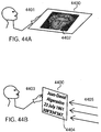
- a smartphone, tablet or laptop computer may capture the superposition shapes forming a visible message and verify its authenticity with authentication software operable for recognizing the message and for comparing its signature with signatures located in its memory, or by sending the visible message or its signature to a remote server located on the Internet and receiving a reply indicating whether the visible message is authentic or not.
- An apparatus for producing superposable revealing layer grating and base layer lenslet gratings that show superposition shapes forming a recognizable message comprises a computer with a software module interacting with the user, interacting with other computers or reading instructions from a file in order to select a superposition technique from the set of 1D moires, 2D moires, random moire, level line moire, lenticular image, phase shift and stereoscopic depth synthesizing techniques.
- the same or a different software module is operable for synthesizing the layout of the base layer lenslet gratings and the layout of the revealing layer lenslet grating according to the selected superposition technique.
- the apparatus further comprises means to expose and develop resist structures laid out according to the layout of the lenslet gratings, heating means operable to apply a reflow process to the exposed and developed resist structures, means to create molds containing the negatives of the reflowed resist structures, a roll-to-roll device incorporating the molds to create the lenslet gratings, UV curable material pressed by the roll-to-roll device into the molds, UV illumination means operable to cure the material in the molds and possibly a system to cut and eject the cured material forming the lenslet gratings.
- one roll-to-roll device creates the base layer lenslet gratings on one side of a substrate and a second roll-to-roll device creates the revealing layer lenslet grating on the other side of the substrate, in registration with the base layer lenslet gratings.
- a single roll-to-roll device may create at the same time the base layer lenslet gratings on one side of a substantially transparent substrate and the revealing layer gratings on the other side of the substrate at the same location.
- an additional polymer having an index of refraction lower than the one of the lenslet gratings may be deposited and hardened on top of the cured material forming the lenslet grating.
- This additional polymer creates a flat surface. This can be carried out both for the base and revealing layer lenslet gratings. Then, one may create a fixed setup looking like a flat piece of plastic, but capable of showing dynamically evolving superposition shapes.
- Further fabrication methods comprise polymer jetting devices working like ink-jet printers, possibly located into closed enclosures enabling programmable heating and UV curing.
- lenslet gratings For large size setups of lenslet gratings, it is also possible to directly print the base and revealing layer lenslet gratings by describing them as 3D surface models, converting the surface description into 3D printer head movements and printing these models with a substantially transparent plastic material.
- Such medium to large size setups of lenslet gratings have a high decorative value and may be used for luxury articles, advertisement, exhibitions and in amusement parks.
- the proposed superpositions of revealing and base layers of lenslet gratings offer a strong protection against counterfeits, since these gratings cannot be produced without sophisticated equipment allowing precise lithography and reflow operations.
- Moire superposition techniques are very sensitive to small deviations in layout and superposition. Therefore, a superposition shape image forming a recognizable message cannot be reproduced by counterfeiters without introducing serious deformations.
- the revealing layer grating of lenslets may have a curved layout such as a cosinusoidal layout. Without knowing the parameters of the corresponding layout, faithful reproduction is extremely difficult and time-consuming.
- one or both layers of lenslet gratings may each be encapsulated by a transparent material layer such as a polymer having a lower index of refraction than the index of the lenslets.
- the encapsulating layer has a flat interface with the air and hides therefore the layout of the encapsulated base lenslet grating.
- Such an encapsulation makes it very difficult for a counterfeiter to recover the orientation, size and layout of the lenslet gratings. A unauthorized replication of a setup comprising encapsulated base and revealing layer lenslet gratings is therefore extremely difficult to achieve.
- the shape image created by superposed layers of lenslet gratings forms a recognizable message that dynamically evolves in synchronization with the movement of an observer. Since it is the movement of the human observer's eyes that drives the evolution of the message, there is an immediate feedback. Such a feedback is unusual and strongly attracts the attention of the observer. Several persons may simultaneously observe the superposed layers of lenslet gratings. Every person will see from a different spatial position a slightly different instance of the dynamically evolving message.
- the presented fixed setups of revealing and base layer lenslet gratings yield superposition shape images that have a high esthetical and decorative value and may also be attractive for luxury products such as watches, smartphones, perfumes, expensive drinks, for clothes such as a dress, a skirt, a blouse, a jacket, shawls and pants as well as in bikes and cars.
- Superposed revealing and base layer lenslet gratings may also be used for advertisement, for the decoration of buildings, for showing surprising messages on exhibition walls, and in amusement parks.
- the superposition images generated by the phase-shift techniques, 1D and 2D moire techniques, shape level line moire techniques and lenticular image synthesizing techniques result from sampling a base layer comprising foreground and background shapes by a revealing layer made of an array of lenslets.
- the present invention aims at replacing the base layer printing or patterning techniques used for producing the base layer foreground and background shapes known from the prior art by populating the foreground or background areas of the base layer with substantially cylindrical lenslet gratings.
- the cylindrical base layer lenslets have a substantially smaller replication period than the replication period of the cylindrical lenslets forming the 1-dimensional revealing layer sampling lenslet grating.
- the base layer cylindrical lenslets have a substantially smaller replication period than the period of the revealing layer 2-dimensional grating of spherical sampling lenslets.
- the base layer cylindrical lenslets should have substantially the same replication period as the revealing layer grating of cylindrical lenslets.
- cylindrical lenslets or "ID lenslets” as a generic term for lenslets whose cross-section are e.g. a section of a circular disk or a section of a parabola and that follow straight or curvilinear lines.
- a grating of cylindrical lenslets may cover a region of the plane. Between each lenslet of a grating of cylindrical lenslets, there may be no space or a small space. The period of such a grating is defined as the repetition period its cylindrical lenslets.
- Gratings of cylindrical lenslets are often fabricated from a description of longitudinal rectangles by applying lithographic and reflow techniques.
- a "longitudinal rectangle” is defined as a relatively long and thin quadrilateral having a constant width. Cylindrical lenslets following a long straight or curvilinear path are fabricated from a description of "longitudinal stripes" of constant width.
- spherical lenslets spherical lenslet grating
- 2D lenslet grating a generic term for lenslets that may fill the space in a repetitive 2D manner, e.g. as a regular 2D array.
- Their shape may be spherical, aspherical or partly spherical and partly non-spherical.
- multi-lenslet setup refers to a fixed setup comprising superposed base and revealing layer gratings.
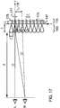
- the revealing layer grating ( FIG. 17 , 143 ) and the base layer gratings ( FIG. 17 , 174 ) are parallel and have in common a plane on which the revealing layer grating samples the light concentrated by the base layer lenslet gratings ( FIG. 3 , 303 , FIG. 17 , 147 ).
- revealing layer lenslet grating in the singular form for the revealing layer (e.g. FIG. 8 , 801 ) and "base layer lenslet gratings" in the plural form because the base layer comprises many base layer micro-shapes (e.g. FIG. 4B , 404, 405, 406 ) that are each covered by a lenslet grating.
- base layer comprises many base layer micro-shapes (e.g. FIG. 4B , 404, 405, 406 ) that are each covered by a lenslet grating.
- recognizable message for the message that is generated as a superposition shape image by the superposed base and revealing layer lenslet gratings.
- "Recognizable” means that either a human being or a computing system is capable of recognizing the message, being it a picture with recognizable elements such as a flag, a face, a house, a forest, a horse, be it a string of letters such as a number or a code formed of numbers and letters, be it a 1D or 2D barcode, or be it a QR-code recognizable by a computer or a smartphone.
- smartphone for a computing device incorporating a camera and being connected to a server for information exchange.
- Commercially available tablet or laptop computers may also perform the same actions as the smartphone.
- FIG. 1 illustrates a multi-lenslet setup 100 comprising the revealing layer cylindrical lenslet grating 101 on top of a substantially transparent substrate 103.
- the base layer comprises a cylindrical lenslet grating 102 forming the foreground of a vertically compressed letter "E" (110).
- the base layer lenslets have their cylindrical parts on the back side (102, 107) of the setup. This setup may be observed by looking 106 from the front side of the revealing layer lenslet grating 101.
- the incoming light 105 irradiates the setup from the backside, i.e. from the base layer lenslet gratings.
- Part 100 of the figure represents the multi-lenslet imaging setup, part 110 an enlargement of one of the replicated lenslet gratings forming a base layer base band (see Section "Creating 1D moire with the multi-lenslet setup) and part 120 an enlargement of a part of the base layer grating comprising two cylindrical lenslets.
- FIG. 2 illustrates a cross-section 201 through either a cylindrical lens (for line oriented superposition effects) or a spherical lens (for a 2D moire) being part of the revealing layer.
- This revealing layer is superposed with base layer lenslet gratings 208 shown as cross-sections across the base layer 202.
- the plane 203 is the focal plane of the revealing layer lenslets on which the base layer cylindrical lenslets concentrate the incident light.
- the revealing layer cylindrical or spherical lenslet is repeated at a period T r (206). Its width is W r (207) and its focal length is f r (208).
- the cylindrical lenslets 213 forming the base layer 202 cover the base layer foreground shape 208 and do not cover the base layer background shape 209. These lenslets have a period T bl and have a focal length f b which, in the case of a 1D moire, 2D moire and of lenticular images, are considerably smaller than the revealing layer cylindrical lens period T r and focal length f r , respectively.
- a substantially transparent substrate whose thickness h s (212) is related to the sum of the focal lengths of the revealing and the base layer lenslets minus the lens heights e r and e b (see FIG. 2 ), i.e. h s ⁇ f r + f b - e r - e b .
- the observer located at a normal viewing distance from the revealing layer may view the multi-lenslet imaging device formed of the revealing and base layers from one angle (e.g. perpendicularly, see 210) or from another angle (e.g. angle ⁇ , see 211).
- the revealing layer lenslets sample the base layer either at a location where the base layer lenslets are present or at a location where they are absent. Regions with lenslets create a bright texture differentiating themselves from the regions without lenslets. This differentiation is at the base of the superposition images viewed by the observer.
- the revealing layer lenslets scan their focal plane 203 close to the base layer, thereby propagating the light intensities created by the presence or the absence of the base layer lenslets onto the observer's eyes.
- Multi-lenslet setup with similar revealing layer and base layer periods.
- the superposition of an array of revealing layer lenslets having a large period and of an array of base layer lenslets having a small period is adequate for the 1D and the 2D moire synthesizing methods, for some of the level line methods, for some of the phase shift synthesizing methods and for the lenticular image synthesizing methods.
- the revealing layer cylindrical lenslets and the base layer cylindrical lenslets shall have the same period, or an integer multiple of that period, but are in some portions of the superposition image shifted one in respect to the other.
- the focal plane 303 is defined by the focal length of the revealing layer lenslets.
- the base layer lenslets concentrate the light on the focal plane of the revealing layer lenslets.
- the base layer lenslets need not necessarily focus the light on the focal plane sampled by the revealing layer lenslets.
- Their distance 309 to the focal plane can be different from f b by up to ⁇ 20%. A simple concentration of the incident light is sufficient.
- the observer 335 is located at a certain distance from the front of the setup, typically 35 cm, when the setup is located on a security document or a valuable article.
- a strong visual effect is obtained by illuminating the multi-lenslet imaging device with spatially varying intensities or colors, for example a display or LEDs (light emitting diodes) showing red 354, green 355, blue 356 and white 357 colors.
- continuous or non-continuous intensity and/or color variations also create a strong visual effect.
- the base layer lenslets are shifted in respect to the revealing lenslets.
- the base layer lenslet 302a with center at position 323 is in phase with the revealing layer lenslet 301a with center at position 320.
- the base layer lenslet 302b with center at position 324 is shifted by ⁇ b (340) in respect to revealing layer lenslet 301b with center at position 321.
- the base layer lenslet 302c with center at position 325 is shifted by ⁇ c (341) in respect to revealing layer lenslet 301c with center at position 322.
- the base layer lenslet When the base layer lenslet is in phase, illuminated region 365a is observed by the observer as the color 355 (green in the present example) sampled by the revealing layer lenslet 301a.
- the base layer lenslets are out of phase, e.g. lenslet 302b with center 324 is at relative phase ⁇ b lT b (340), a different part of the illuminated focal plane is sampled by the corresponding revealing layer lenslet 301b, here region 366b of the focal plane, illuminated by portion 356 of the illuminating light.
- lenslet 302c is at phase ⁇ c / T b and revealing layer lenslet 301c samples region 367c of the focal plane illuminated by portion 357 of the illuminating light.
- illuminating light light coming through a window may also be convenient, by having green portions from the trees and the grass, gray and yellow portions from buildings and blue portions from the sky. Light reflected from a variable intensity and variable color background such as a wall is also suitable. Light emitted by several LEDs illuminating the lenslet setup from behind also provides excellent visual effects.
- electronically driven multi-LED devices i.e.
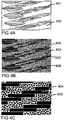
- a light diffusing behavior in regions where the base layer lenslets are absent can be achieved by placing small lenses 403 randomly across the regions forming the background of the base layer shape.
- These diffusing microlenses, line-oriented (ID) such as small segment cylindrical lenses or two-dimensional (2D) such as spherical or aspherical lenses should have a focal length significantly different from the cylindrical lenslets 401 present in the base layer.
- ID line-oriented
- 2D two-dimensional
- FIG. 4A shows the layout of the foreground regions 401 with the thin rectangular areas specifying the locations of the cylindrical lenses and the empty background regions 402.
- FIG. 4B shows the same views under a microscope where the cylindrical lenslets 404 form lenslet gratings that cover the foreground regions. Background regions are covered with the randomly positioned diffusing microlenses 403.
- FIG 4C shows an enlargement of a part of FIG 4B .
- US patent 7,710,551 discloses a "ID moire image layout computation method" allowing the computation of the direction and the speed in which 1D moire image shapes move when the revealing layer samples, when tilting the setup, successive locations of the superposed base layer.
- Formula (1) to (5) describe according to US patent 7,710,551 (inventors Hersch and Chosson) the mathematics used for computing the layouts of the base layer, given the layouts of the revealing layer and of the moire layer.
- the corresponding moire shapes 503 "VALIDE" are obtained by the revealing layer sampling lines 502a, 502b, 502c, ... having period T r sampling the base bands successively at different locations.
- the layout of the 1D moire image in the transformed space is expressed by a geometric transformation M ( x t , y t ) which maps the transformed moire space locations ( x t , y t ) back to original moire space locations (x,y).
- the layout of the revealing line grating in the transformed space is expressed by a geometric transformation G ( x t ,y t ) which maps the transformed revealing layer space locations ( x t , y t ) back into the original revealing layer space locations (x',y').
- the layout of the base band grating in the transformed space is expressed by a geometric transformation H ( x t ,y t ) which maps the transformed base band grating locations ( x t , y t ) back into the original base band grating locations (x',y').
- Transformation H ( x t ,y t ) is a function of the transformations M ( x t , y t ) and G ( x t ,y t ) .
- M (x t ,y t ) ( m x ( x t ,y t ,m y ( x t , y t ))
- G ( x t , y t ) (x, g y ( x t ,y t )
- H ( x t ,y t ) ( h x ( x t ,y t , h y ( x t , y t )).
- Example A Rectilinear 1D moire image "EPFL" formed of revealing and base layer lenslets
- FIG. 6A shows schematically an example of a rectlinear moire image 603 formed of the superposition of base layer base bands 601 with foreground shapes 610 (black) and background shapes 611 (white) and a revealing layer 602 formed of an array of sampling lines 612.
- the revealing layer period T r is 400 ⁇ m
- the transparent sampling lines 612 show the positions of the centerlines on which the cylindrical lenslets of the revealing layer are placed.
- FIG. 6B is an enlarged view of a part of FIG.
- FIG. 6A shows the layout of the base layer rectangle array 615 for producing the grating of cylindrical oblique lenslets forming the base layer foreground shapes 610.
- FIG. 6C shows a realization of the layout shown in FIG. 6B with a picture of the actual base layer lenslet grating 620 laid out according to the layout 610 and along the obliquely laid out rectangle array 615.
- the base layer backgound shape 611 is populated with randomly placed 2D lenses 622 having a width between 8 ⁇ m to 12 ⁇ m and focal lengths between 20 ⁇ m and 30 ⁇ m. Note that the obliquely laid out base layer lenslet grating 620 creates sharper moire shapes.
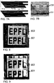
- FIG. 7A shows an alternative base layer layout for the small compressed "F" 610 of FIG. 6A .
- FIG. 7B shows a picture of a region 701 of the corresponding implemented base layer lenslet grating seen under a microscope.
- the background 711 is populated by a vertically laid out lenslet grating 721 with a period of approximately one third the period of the horizontally laid out foreground lenslet grating.
- the background lenslet grating Since the background lenslet grating has a focal length much smaller than the focal length of the foreground lenslet array, the light traversing it will be diffuse at the depth of the focal plane of the revealing layer lenslet array. In contrast, the light traversing the foreground lenslet grating will be concentrated into the focal plane of the revealing layer lenslet grating. This statement is valid both for base layer backgound shapes populated with small spherical lenslets or populated with small cylindrical lenslets. The different light concentration behavior of foreground and background base layer lenslet gratings yields the contrast that enables revealing the superposition images (ID moire, 2D moire, 2D random moire, lenticular images).
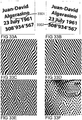
- FIG. 8 shows a photograph of a device formed of two lenslet layers, with the "EPFL" moire shape 802 formed of the superposition of the cylindrical base layer lenslets partly shown schematically in FIG. 7A and of the cylindrical revealing layer lenslets 801.
- the revealing layer lenslet array has a lenslet period of 400 ⁇ m, with a lenslet width of 385 ⁇ m and a gap of 15 ⁇ m between individual lenslets.
- FIG. 9 is a photograph of the same device as in FIG. 8 , but viewed from a slightly different angle.
- the "EPFL" moire shape 902 in FIG. 9 has moved vertically in respect to the "EPFL" moire shape 802 shown in FIG. 8 .
- the encapsulating material increases the focal length of the lenslets calculated according to formula (12), where the index of refraction of the encapsulating material has to be inserted as n m .
- Example B Circular band moire image and rectilinear revealing layer.
- constant c m expresses a scaling factor
- constants c x and c y give the center of the circular moire image layout in the transformed moire space
- w x expresses the width of the original rectilinear reference band moire image and function atan ( y,x ) returns the angle ⁇ of a radial line of slope y / x , with the returned angle ⁇ in the range ( -
- FIG. 10A The corresponding desired reference circular moire image is shown in FIG. 10A , 1003 and appears as the message "VALID OFFICIAL DOCUMENT".
- g y ( x t ,y t ) y t (1002).
- curvilinear base layer layout equations express the geometric transformation from transformed base layer space to the original base layer space.
- the corresponding curvilinear base layer in the transformed space is shown in 1001.
- the resulting moire image formed of the superposition of the base layer (1001) and of the revealing layer (1002) is shown in 1003.
- the revealing layer 1002 is moved vertically over the base layer 1001
- the corresponding circular moire image patterns move radially and change their shape correspondingly.
- the letters become wider.
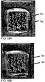
- FIG. 10B shows a photograph of a microscopic enlargement of part of the base layer lenslets 1005 forming the base layer letters "..UME..” as embodiment of the lower central part of the base layer of FIG. 10A (1001).
- the circular moire shape image appears.
- This moire shape image is schematically shown in FIG. 10A (1003) and also shown as a photograph in FIG. 11 when embodied as the setup formed of the superposed base and revealing layers of lenslet gratings.
- curvilinear revealing layer Let us now take a curvilinear revealing layer and still generate the same desired curvilinear moire image as in the previous example B.
- the corresponding cosinusoidal revealing layer is shown in FIG. 12 , 1202 .
- curvilinear base layer layout equations express the geometric transformation from the transformed base layer space to the original base layer space.
- the corresponding curvilinear base layer is show in 1201.
- the superposition of the curvilinear base layer 1201 and curvilinear revealing layer 1202 yields moiré image 1203.
- the revealing layer 1202 is moved vertically over the base layer 1201, the corresponding circular moiré image patterns move radially and change their shape correspondingly, as in the example shown in FIGS. 12 and 13 .
- example C embodied as a setup formed of two superposed layers of lenslets according to Section "Multi-lenslet imaging setup with large revealing layer periods and small base layer periods".
- the base layer grating of lenses is placed at all foreground areas ("white" areas in FIGS.
- the revealing layer grating of lenslets is formed of cylindrical lenslets following the cosinusoidal transparent ("white" in FIG. 12 ) lines 1202 of the revealing layer.
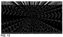
- FIG. 13 shows that a slight displacement of the sampling locations of the revealing layer cylindrical lenslets obtained by a vertical shift of the revealing layer, or in case of a fixed setup obtained by tilting, yields a radial displacement of the revealed circular message.
- the message "VALID OFFICIAL DOCUMENT" has moved radially in respect to its position in FIG. 12 .
- each eye of the observer sees at each position a slightly different sampling of the base layer, i.e. each eye sees a slightly different moiré image. Due to their slightly different sampling phase, these moiré images are slightly displaced one in respect to another and yield, thanks to human stereoscopic vision, an image having a certain depth.
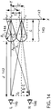
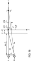
- FIG 14 shows schematically the geometry used for calculating the offset between a moiré shape seen by the left eye ("L”) and a moiré shape seen by the right eye (“R”).
- This moiré offset also called disparity, determines the apparent depth of the moiré shape.
- the space T E between the left eye 145 and right eye 146 is generally around 63mm.
- d a viewing distance from the eyes to the setup.
- the setup comprises a revealing layer 143 formed of a 1D grating of lenticular lenslets of replication period T r and of a base layer 174 (see FIG. 17 , showing the same view as FIG. 14 , at a different enlargement) formed of gratings of small cylindrical lenslets ( FIG.
- This x-increment ⁇ x r is identical to the projected revealing layer period T r '.
- the projected revealing layer period T r ' also called “apparent revealing layer period” is obtained by projecting revealing layer period T r from the plane 144 connecting the central points C 0 , C 1 , C 2 ,... of the revealing layer lenses onto the focal plane 147 of the revealing layer lenses.
- FIG. 15 shows the setup from above ( x-y plane), with separately the base layer 151, the moiré shape seen by the left eye 152 and the moiré shape seen by the right eye 153 for the case where the base layer band period (the period of repetition of the small "M” in FIG. 15 ) is smaller than the apparent revealing layer period, i.e. T r '> T b .
- T r the apparent revealing layer period
- the vertical dashed lines x 0R , x 1R , x 2R , x 3R , x 4R ... are the sampling lines of the revealing layer lenslets when looked upon from the right eye.
- the base layer shapes here small letters "M", each one inscribed within a base band
- the sampling lines seen by the left eye create the moiré shapes 152 that appear to the left eye
- the sampling lines created by the right eye create the moiré shapes 153 that appear to the right eye.
- the moiré height H' is the moiré height apparent to the eyes in the case of a revealing layer array of cylindrical lenslets sampling a base layer formed of vertical base bands, where the base band shapes are defined by small cylindrical lenslet gratings (e.g. 620 in FIG. 6C ).
- Apparent moiré height H' is calculated in the same manner as the classical moiré height without gap between revealing layer and base layer, but using as revealing layer period the revealing layer period projected onto the focal plane (Eq. (17)).
- FIG. 16 shows the same elements as FIG. 15 , with separately the base layer 161, the moiré shape seen by the left eye 162 and the moiré shape seen by the right eye 163 but for the case where the base layer band period is larger than the revealing layer period, i.e. T b > T r '.
- the layout of the base layer shape (letter M upright in positive x-direction) is inversed in respect to the layout of the moiré shape (letter upright in negative x-direction).
- This is expressed in formula (18) by the negative apparent moiré height H ', resulting from the fact that T r ' - T b is negative.
- Formula (19) also yields a negative offset ⁇ m .
- the apparent depth is negative and the resulting moiré shapes float in front of the setup made of the two lenslet layers at a distance being expressed as a negative apparent depth value.
- the moiré shapes shown in FIGS. 19A and 19B are also examples for stereo moiré vision.
- a revealing layer period T r 0.4mm
- a base layer period T b 0.353 mm
- a viewing distance d 500mm
- a radius of curvature R r 0.4mm.
- Eq. (23) we obtain a calculated depth z m of 6.01 mm, i.e. the moiré shapes viewed by superposed revealing and base lenslet layers have an apparent depth of 6mm. They seem to float behind the setup made of the two lenslet layers.
- the layout of the 2D moiré image in the transformed space is expressed by a geometric transformation M ( x t , y t ) which maps the transformed moiré space locations ( x t , y t ) back to original moiré space locations ( x,y ).
- the layout of the 2D revealing array in the transformed space is expressed by a geometric transformation G ( x t , y t ) which maps the transformed revealing array space locations ( x t , y t ) back into the original revealing layer array space locations ( x',y' ).
- the layout of the 2D array of micro-shapes in the transformed space is expressed by a geometric transformation H ( x t ,y t ) which maps the transformed 2D micro-shape array locations ( x t , y t ) back into the original 2D micro-shape array locations ( x',y' ).
- a desired rectilinear or curvilinear 2D moiré image layout is specified by its moiré height H y and width H x in the original coordinate space ( x',y ') and by its geometric transformation M ( x t ,y t ) .
- a desired revealing layer layout of the 2D sampling array is specified by the period T rx along the x -coordinate and T ry along the ⁇ -coordinate of its elements in the original space ( x',y' ) and by its geometric transformation G ( x t , y t ).
- the base layer layout of the 2D array of micro-shapes is specified by the period T bx along the x -coordinate and T by along the ⁇ - coordinate of its elements in the original space ( x',y' ) and by its calculated geometric transformation H ( x t , y t ).
- the base layer geometric transformation H ( x t , y t ) is obtained as function of the transformations M ( x t , y t ) and G ( x t , y t ).
- the revealing layer is embodied by a 2D array of lenslets, shown schematically by two lenslets in Figure 21 , 2105 and the base layer by a 2D array of virtual micro-shapes shown schematically by two "$" signs 2103, created by having a 1D array of cylindrical lenslets 2102 covering the foreground of each micro-shape.
- each microlens samples a different position within the virtual micro-shapes of the base layer. For example, from a given observation position, microlens 2116 samples position 2106 within the background of the micro-shape whereas microlens 2117 samples position 2107 within the foreground of the micro-shape.
- the background of the virtual micro-shapes 2002 may be embodied by no lenses or by randomly located small microlenses 2022 diffusing the incoming light (see Section "Reinforcing the contrast of the base layer by diffusing microlenses").
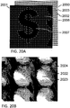
- FIG. 20A shows the base layer 2000 and revealing layer 2001 auxiliary digital images used to create the base layer embodied by arrays of small size 1D cylindrical lenslets ( FIG. 20B , 2023 ) and the revealing layer embodied by 2D lenslets whose size is of the same order of size as the size of the 2D base layer micro-shapes.
- FIG. 20B shows a photograph of a microscopic view focussed on the base layer ("$" signs with foreground 2023 and background 2022) with the revealing layer microlenses 2024 appearing thanks to backlight illumination of the microscope.
- the resulting 2D moiré shape 2007 represents the enlarged, rotated and sheared dollar sign 2003.
- the revealing layer lenslets of the 2D lenslet grating are centered at the holes 2006 of the revealing layer.
- the gratings of small size 1D cylindrical lenslets 2023 cover the foreground shapes 2003 of the virtual 2D array of micro-shapes.
- the background 2002 of the virtual micro-shapes is covered by randomly placed microlenses 2022 having random sizes e.g. between 8 ⁇ m to 12 ⁇ m, i.e. a diameter considerably smaller than the repetition period of 27 ⁇ m of the lenslets forming the base layer lenslet gratings.
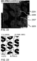
- FIG. 22 shows a photograph of an embodiment of the 2D moiré multi-lenslet setup, consisting of a thin glass plate 2204.
- the base layer is pasted, which is embodied by 1D gratings of cylindrical lenslets yielding the virtual micro-shapes.
- the 2D revealing layer lenslet grating 2205 is pasted.
- the resulting moiré foreground shapes 2206 and moiré background shapes 2207 are clearly visible.
- the dollar sign moves vertically when tilting the setup horizontally, i.e. rotating it slightly around a vertical axis and moves diagonally (at -45 degrees) when tilting the setup vertically, i.e. rotating it slightly around a horizontal axis.
- the base layer 1D gratings of cylindrical lenslets covering the foreground of the virtual microimages have a lenslet repetition period of 16 ⁇ m.
- the revealing layer 2D lenslet repetition periods are 400 ⁇ m horizontally and vertically.
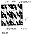
- FIG 23 gives the coordinates of the desired moiré layout.
- the computer program finds according to Eq. (27) the corresponding locations x , y within the moiré image, reads at each location the intensity or color and copies it back into the current base layer location ( x", y" ). This enables creating the corresponding base layer 2D array of virtual micro-shapes. The foreground of these virtual micro-shapes is then used as a mask for fabricating the 1D array of cylindrical lenses.
- Curvilinear moiré layouts described by a geometrical transformation M ( x,y ) may be produced by further applying the transformation H ( x,y ) described in Eq. (25) to the base layer array of virtual micro-shapes.
- Level line moirés rely on the principle stating that the level lines of an elevation profile appear as moiré lines in the superposition of a base layer embodied by a line grating whose lines are shifted by an amount substantially proportional to the elevation and of a revealing layer embodied by the unshifted line grating.
- This elevation profile is conceived with the goal of producing strong intensity or color variations at the shape boundaries and of incorporating level lines that yield shapes similar to the original bilevel shape.
- the elevation profile level lines are revealed as moiré when superposing the revealing line sampling grating on top of the synthesized base layer line grating incorporating the spatially dependent line shifts.
- the moving succession of moiré level lines creates the impression of beating shapes.
- the revealing layer is embodied by an array of cylindrical lenslets and the base layer is also embodied by an array of cylindrical lenslets of a similar period, but shifted in respect to the revealing layer lenslets according to the elevation profile.
- level lines of the colors of the light sources move inwards and outwards from the shape centers towards their boundaries and from the shape boundaries towards the shape background centers.
- a same geometric transformation applied to both the base and the revealing layers yields the same moiré shape that would be obtained without geometric transformation.
- This enables creating cylindrical lenslet arrays whose axes follow a spatial path given by a function , e.g. a cosinusoidal function defined by its period and amplitude.
- variable thicknesses by cylindrical lenslets one may cover the foreground area of the variable width halftone lines forming the base layer by oblique base layer cylindrical lenslet gratings whose lenslets have a small repetition period, in a similar manner as was carried out for 1D moiré shapes in Section "Creating 1D moiré with the multi-lenslet imaging setup", see Example A, FIGS 6A, 6B, and 6C with base layer cylindrical lenslet grating 620.
- the centerlines of the thick lines of the base layer form a line grating parametrized by the integer values of the base layer line index n .
- T b defines the line period.
- Equation (35) fully describes the family of moiré fringe lines ( FIG. 25A , 2501 ). Integer values of k correspond to the centerlines of the "thick lines" forming the moiré fringe lines and real values of k correspond to lines located within bands whose boundaries are formed of the moiré center lines.
- Level line moirés enable visualizing the level lines of an elevation function G ( x,y ) by superposing a base layer grating whose horizontal lines are vertically shifted according to the elevation function G ( x,y ) and a horizontal revealing layer grating having the same line period as the base layer grating.
- the revealed moiré fringe lines form the level lines of elevation function G ( x,y ) .
- FIG. 25B shows the result of applying different non-linear geometrical transformations to the gratings of FIG. 25A .
- FIG. 26A In order to produce a level line moiré, we start with a bilevel shape as shown in FIG. 26A .
- a bilevel shape As shown in FIG. 26A , we obtain an intermediate skeleton representation, FIG. 26B of the bilevel image.
- d krel expresses the relative distance of pixel ( x,y ) to its respective skeleton on a scale between 0 and 1.
- d krel maps the relative distances d krel onto elevations.
- Clearly visible moiré shapes with a high gradient or a discontinuity at their shape boundary are obtained by assigning to foreground shapes the elevations between 0.5 and 1 and to background shapes the elevations between 0 and 0.5.
- each band is formed of an intensity gradient ( FIG. 27 , 2701 ) perpendicular to the band orientation.
- this grating of bands is vertically shifted in proportion to the elevation at the corresponding location.
- the resulting shifted base layer is shown in ( FIG. 27A ).
- a one period maximal shift corresponds to the maximum of the elevation profile.
- By superposing the sampling revealing layer grating on top of the shifted base layer line grating one obtains the moiré shapes formed by the level lines of the elevation profile ( FIG. 27B ).
- the base layer is formed of a 1D grating of cylindrical lenslets centered on the shifted bands having substantially the same period as the unshifted 1D grating of cylindrical lenslets forming the revealing layer.
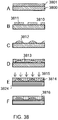
- FIG. 28A shows a photograph of an embodiment of the level line moiré multi-lenslet setup. This setup consists of a thin glass plate 2804 on whose back side the base layer embodied by the 1D grating of partially shifted cylindrical lenslets is pasted and on whose front side the non shifted 1D grating of cylindrical lenslets 2805 is pasted. The resulting moiré level lines 2806 are clearly visible as constant intensity lines located between the foreground or background shape skeletons and the moiré shape boundaries.
- FIG. 28B shows an enlargement of a portion 2808 of the moiré shape image of FIG. 28A , which shows that a high intensity 2810 appears at positions where the base layer grating of cylindrical lenses concentrates the incoming light at the positions sampled by the revealing layer grating of cylindrical lenses, i.e. along the viewing direction.
- FIGS. 29A, 29B, 29C and 29D show each the front lenslet 2920, respectively 2950 representative for the revealing layer grating of cylindrical lenslets in front of the eye 2900 and the back lenslet 2921, respectively 2951 representative for the base layer gratings of cylindrical lenslets behind the revealing layer grating.
- the intensity is the highest ( FIG. 28B , 2810 ) when the two gratings 2920 and 2921 are in phase 2901.
- a lower intensity appears at positions where the base 2950 and revealing 2951 layer gratings cylindrical lenses are shifted one in respect to another.
- the resulting intensity is the lowest.
- the base layer lenslet concentrates the incoming light 2905 at a position 2930 different from the sampling positions 2931 of the revealing layer lenslet and the corresponding locations are dark.
- FIG. 29D at positions where the two gratings are shifted 2904 by a certain fraction ⁇ of the grating period, the light concentrated by the base layer lenslet 2940 is sampled by the revealing layer lenslet 2941 and provides a high intensity to the viewer 2900.
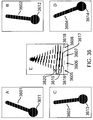
- FIG. 30A shows a geometrically transformed base layer grating formed of an array of base layer bands each one containing an intensity gradient having a triangular shape.
- the geometric transformation is a cosinusoidal transformation as defined by Eq. (40).
- the intensity gradient perpendicular to the band orientation (see enlargement 3001) is representative for the light concentrated by the base layer lenslet gratings on the focal plane of the revealing layer grating.
- This gradient intensity band is vertically shifted by an amount substantially proportional to the elevation profile of the motives to be revealed as moiré level line shapes, here the letter “A” and the "heart” motives, see the upper half of FIG. 26C .
- moiré level line shapes here the letter “A” and the "heart” motives
- FIG. 30C When superposed with a sampling grating of revealing layer cylindrical lenslets laid out along the center of the transparent lines (white lines in FIG. 30B ), the corresponding level line moiré shape appears ( FIG. 30C ).
- FIG. 30D By slightly displacing the sampling positions of the revealing layer lenslet grating on its focal plane, i.e. in respect to the base layer light concentrating lenslet gratings, a different instance of the same level line moiré shape appears ( FIG. 30D ).
- These sampling locations are displaced when viewing from a different angle the setup formed of the base and revealing layer lenslet gratings, see Section "Visible effect obtained by the level line moi
- the level line moiré is also geometrically transformed and may become curvilinear.
- FIGS. 19 and 20 in US Patent 7'305'105 show the resulting geometrically transformed level line moiré.
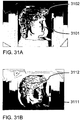
- a grayscale image such as a human face
- a multi-lenslet setup made of a base layer grating of cylindrical lenslets which are shifted according to the face intensities and a revealing layer grating of unshifted cylindrical lenslets
- the setup shown in the examples of FIGS 31A and 31B is a concrete embodiment made with gratings of cylindrical lenslets having an individual lenslet period of 50 ⁇ m. Depending on the application, cylindrical lenslet periods of a few microns to centimeters are possible.
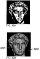
- a further variant of creating level line moirés by base layer lenslets forming a halftone image consists in creating from an original image (e.g. FIG. 32A ) a halftone image (e.g. FIG. 32B ) with substantially parallelogram shaped black halftone screen elements (enlargement of rectangular area 3201 in FIG. 33F ) embedding the elevation profile(s) (e.g. FIGS. 33A and 33B ) of the message to be revealed as level line moiré shape. This is carried out by creating the base layer halftone lenslet array as follows.
- the dither band repetition period is substantially larger than the repetition period of the lenslets forming the base layer lenslet gratings.
- the revealing layer lenslet grating period is the same as the dither band repetition period.
- the present embodiment enables creating, with base layer lenslet gratings, a halftone image such as the one shown in FIG. 32B .
- the quasi-parallelogram shape of the black halftone elements facilitates the placement of the base layer lenslets and enables, when superposing a revealing layer lenslet grating at a first orientation (3502), to reveal a first hidden message 3505 in one orientation (see FIG. 35A corresponding to the rectangular surface 3202 in FIG.
- FIGS. 35A and 35B corresponds to rectangular area 3202 in FIG. 32B .
- the solution shown above relies on small period lenslet gratings for the black screen element parts and no lenslets for the black screen element parts.
- the light through the lenslets gets diffused whereas light through the areas without lenslets has a strong intensity.
- Other variations are possible, for example by replacing the black parallelogram parts containing the cylindrical lenslet arrays with randomly placed light diffusing microlenses, as described in Section "Reinforcing the contrast of the base layer by diffusing microlenses".
- the present embodiment has the advantage of showing a halftone image, e.g. the face of a known person or the face of the document holder and at the same time being able to reveal, when superposed with the revealing layer lenslet grating, additional information, such as the name and birth date of the person whose face appears as halftone image.
- This solution is specially promising when using digital systems that are able to print personalized lenslet grating layouts.
- a smartphone, tablet or laptop computer programmed to acquire the halftone image formed by the base layer lenslet gratings, to perform by software an "AND" operation between the acquired halftone base layer image and a corresponding revealing layer array of transparent lines located in memory, to show the resulting additional information on the display and/or to recognize the information content by optical recognition software and to send the resulting information content to a server for validation (similar to FIG. 46 and Section "Verification of the authenticity of a security feature relying on layers with superposed gratings of lenslets", third embodiment).
- the constant intensity or color lines representing the level lines of the elevation profile incorporated into the base layer by shifts of its lenslet gratings appear to move between the elevation shape foreground skeleton and the shape boundaries and between the elevation shape boundaries and the shape background skeleton.
- the level lines are represented by constant gray values.
- the different sampling positions of the revealing layer in respect to the base layer shown in FIGS. 30C and 30D create a different mapping between the level lines of the elevation profile and their representation as constant intensity or constant color lines.
- the constant intensities or colors seen as level lines depend on the backside illumination that should vary according to the incident angle on the base layer lenslets (see incident light in FIG. 3 , at angular orientations 354, 355, 356, 357).
- the lenticular image synthesizing techniques rely on base layer slicing, sampling, compression and re-assembling and on revealing layer sampling.
- a number of input images e.g. the 4 images shown in FIG. 36 , boxes A, B, C and D are sliced and compressed by a factor of 4, then superposed, yielding the base layer assembly shown in box E.
- Individual images 3601, 3602, 3603, 3604 become image parts 3605, 3606 , 3607, 3608, respectively.
- Slices 3611, 3612, 3613 and 3614 become after compression (scaling down in one direction) slices 3615, 3616, 3617 and 3618, respectively.
- the black foreground slices shown in box E are embodied by gratings of oblique cylindrical lenslets.
- the background (white) is left empty or filled with small microlenses diffusing the light.
- the revealing layer grating of lenslets has lenslets with the same period as the distance 3620 between successive slices of a same image part.
- FIGS. 37A, 37B, 37C, and 37D show photographs of a setup made of base and revealing grating lenslets.
- This setup shows as superposition shapes four successive views representing a running rabbit that appear when tilting the setup vertically.
- the revealing layer cylindrical lenslets are horizontally oriented and have a period of 400 ⁇ m, with each cylindrical lens having a width of 385 ⁇ m followed by a gap of 15 ⁇ m.
- the base layer gratings covering the foreground of the base layer images are formed of cylindrical lenslets having a period of 16 ⁇ m, with each cylindrical lens element having a base width of 14 ⁇ m and a gap of 2 ⁇ m.
- the base layer gratings are rotated by 15 degrees in respect to the orientation of the revealing layer grating.
- lenslet grating synthesizing techniques described in detail above that create upon observation 1D moiré shapes, 2D moiré shapes, level line moiré shapes or lenticular image shapes are only a subset of the variety of superposition shapes that can be achieved with superposed layers of lenslet gratings.
- These lenslet grating synthesizing techniques can also be used to create in an analogous manner a pair of base and revealing layer random 2D lenslet gratings that show by superposition a single instance of a 2D moiré view, according to US Pat 7,058,202 to Amidror . They can also be used to create a pair of base and revealing layer random 1D lenslet gratings that show a single instance of a 1D moiré shape, according to US Pat. 8,351,087 to Amidror and Hersch .
- a first embodiment relies on a roll-to-roll setup with a single PDMS carrying wheel.
- Points A to D are the same as above, but carried out on a lengthy surface comprising several parts (areas) each one having its gratings of cylindrical lenslets.
- the following steps are carried out.
- steps A to G can be performed both for the base layer gratings of cylindrical lenslets and for the revealing layer gratings of cylindrical lenslets.
- microlenses can be formed in a similar manner as cylindrical lenslets, by also exposing in step B circular disks, as known in the art.
- the final multi-lenslet setup containing the base and revealing layer gratings of lenslets can be obtained by pasting the base layer grating and revealing layer grating together. Registration marks formed of a cross made of 2 cylindrical lenslets located between the separate parts may be helpful for bringing the two layers into registration before pasting them together.
- a second roll-to-roll embodiment consists in imprinting both layers of the substrate on the same installation, as shown in FIG. 40 .
- This system relies on one wheel 4001 carrying a first PDMS mold 4011 for imprinting the base layer lenslets and on a second wheel 4002 carrying a second PDMS mold 4013 for imprinting the revealing layer lenslets.
- the system works in the same manner as described for the single PDMS carrying wheel embodiment described previously.
- the material can be encapsulated by a transparent layer of a lower index of refraction, yielding a flat surface.
- step G after the molded cured material 4012 separates from the PDMS, curable material is poored 4060 on the other side of the substrate and is pressed against the second PDMS mold 4013 while rotating along the second wheel 4002 .
- the material is cured by UV light 4021, hardened and finally detached from the PDMS 4014.
- the base layer grating of lenslets 4051 on one side of the substrate is available simultaneously with the revealing layer grating of lenslets on the other side of the substrate 4014.
- registration marks formed of a cross made of 2 small cylindrical lenslets are placed at regular intervals between the separate areas of the gratings.
- the second wheel 4002 can be slightly moved in respect to the first wheel 4001 so as to ensure that the hardened "cross" registration marks made of lenslets are brought into registration at the output of the second wheel.
- individualized gratings of lenslets that comprise an information related to the specific document or valuable article that is to be protected.
- the revealing and base layer gratings of lenslets may be affixed on a box containing valuable drugs, where the superposition image shows as level-line moiré the number characterizing the production series of that drug or its specific identification number.
- an ID card may show as base layer lenslet gratings the halftone image of the card holder and as superposition moiré shape, either as a 1D moving moiré shape or as a level line moiré shape, representing the birth date of the card holder.
- the recently developed 3D printers may also print such lenses with polymer material that at a certain temperature form, due to surface tension, the desired cylindrical or circular lenslet gratings.
- the polymerization can then proceed by irradiating the resulting lenslet gratings with UV light and/or by heating them.
- Large size lenslet gratings e.g. lenslet gratings with a repetition period larger than 1mm, may be manufactured by classical 3D printing with a transparent plastic material.
- the 3D shape of the one sided or in case of a fixed setup of the two-sided lenslet gratings is described by a surface model such as the STL file format for stereolithography.
- the STL description is then entered into the software converting the surface model to printer commands specifying the x-y horizontal displacements and the z vertical displacements of the print head.
- the resulting printed 3D plastic element forms either the base layer lenslet gratings or the revealing layer lenslet grating on top of a flat layer of plastic.
- the resulting printed 3D volume is the fixed multi-lenslet setup directly usable to view the resulting superposition shape image.
- a fixed setup of large size from a few centimeters to several meters, can be used for advertisement and decoration, in exhibitions, for the decoration of walls or in amusement parks.
- a digital fabrication line producing personalized security devices such as identity cards (“ID cards”) comprises a computer ( FIG. 41 , 4110 ) running a computer program that automatically produces the layout of the ID arrays of rectangular areas and 2D arrays of circular areas on which the corresponding cylindrical and spherical lenslet gratings are formed.
- the computer program may carry out the following steps:
- the revealing layer lenslet grating is not individually personalized, it may be fabricated as described in Section "Production of gratings of cylindrical lenslets". If it is personalized, for example by having for personalized security items cosinusoidal revealing layer layouts of different amplitudes, periods and orientations, it may be produced in a manner analogous to the procedure described above for creating personalized base layer lenslet gratings.
- the fabrication of large sized fixed setups of lenslet gratings would comprise the step of conceiving the fixed setup of base and revealing layer lenslet gratings ( FIG. 42 , 4201 ), of deriving 4202 from the parameters and layout of the lenslet gratings a 3D surface description (e.g. STL), of translating the 3D surface description into 3D printing head displacement commands 4203 and of printing 4204 the fixed setup in 3D according to the computed head displacement commands.
- a 3D surface description e.g. STL
- the method for conceiving a security feature ( FIG. 43 ) that is to be incorporated into a document or an article to be secured comprises the following steps.
- the multi-lenslet setup incorporating on its recto the revealing layer grating of lenslets and on its verso the base layer gratings of lenslets provides the clearest superposition shape image when viewed in transmission mode, when light arrives from the back of the setup, e.g. light from a window, light from an artificial light source, light from an array of LEDs or light from a wall. The best effects are achieved when the incoming light varies in intensity according to its incident angle.
- the setup with the recto-verso gratings of lenslets can be incorporated into any document window, .e.g. the window reserved for transmissive effects on opaque paper banknotes, the non-opacified portion of a polymer banknote or a transparent polymer area within a plastic card.
- the recto-verso gratings of lenslets can also be placed on a transparent portion of the polymeric data page of a passport.
- Recto-verso gratings of lenslets can also be easily incorporated into transparent or semi-transparent areas of plastic indentity cards (ID cards) by placing them on both sides of the card. They can be encapsulated by a transparent material such as a polymer with a lower index of refraction than the index of refraction of the lenslets.
- ID cards plastic indentity cards
- the resulting ID card may for example show the face of the ID card holder. By tilting the ID card, the face parts change smoothly their intensities from highlight to dark and vice versa, as shown in FIGS. 31A and 31B .
- Section "Level line moiré produced with a revealing layer lenslet grating of large repetition period and base layer lenslet gratings of a small repetition period forming a halftone image” it is also possible to print the base layer lenslet gratings forming the halftone image on one side of a semi-transparent substrate and the revealing layer lenslet grating on the other side of the semi-transparent substrate. Then, when viewed in reflective mode on a dark background ( FIG. 44A , 4401 ), the halftone image 4402 is visible, e.g.
- transmissive superposition image formed of the superposition of the base and revealing layer gratings becomes visible.
- This transmissive superposition image contains a message such as the name, birth date and ID number of the document holder 4404.
- the setup with the recto-verso gratings of lenslets can also be applied on any package reserving a transparent window for this authentication feature.
- a package containing drugs may incorporate a small transparent window located in its pivoting lid. This transparent window may incorporate on one side the revealing layer grating of lenslets and on the other side the light concentrating gratings of lenslets forming the base layer.
- the lid shows as moiré superposition image the dynamically moving "ORIGINAL DRUG" message.
- Packages that include a transparent part or a transparent window are very often used for selling a large variety of products, including, for example, CDs, DVDs, etc., where the transparent part of the package enables customers to see the product inside the package.
- the transparent parts of such packages may also be used advantageously for authentication and anti-counterfeiting of the products, by using a part of the transparent window for the placement of the recto-verso gratings of lenslets.
- the setup made of the recto-verso gratings of lenslets may also be printed on separate security labels or stickers that are affixed or otherwise attached to the product itself or to the package.
- the shape image resulting from the superposition of the base and revealing layer gratings of lenslets can be visualized by simply looking at the setup incorporating the layers of lenslets.
- This superposition shape image may represent a graphic motif, a symbol or a piece of text that is known to characterize the item that is to be authenticated.
- the superposition shape image becomes animated.
- the relative sampling position of the revealing layer grating can be modified e.g. by a relative translation or a relative rotation of the layers or by tilting horizontally, vertically, or diagonally a fixed setup (e.g. FIG. 45A and FIG.
- the superposition shape image moves (e.g. from 4505 to 4506 ) across the setup (see also evolution of the moiré shape image from FIG. 12 to FIG. 13 ).
- the superposition shape image shows beatings from the foreground and background centers to the borders of that shape and vice-versa (see FIGS. 30C and 30D for two different sampling positions; the constant gray levels follow the shape level lines).
- FIGS. 37A, 37B, 37C and 37D several shape instances give the impression of a dynamically moving shape (see FIGS. 37A, 37B, 37C and 37D ).
- FIGS. 19A and 19B show the 1D moiré messages "VALID” and "OK” that appear at different depth levels and move in opposite directions.
- a person can immediately verify with the naked eye the authenticity of the security item by tilting the fixed setup and verifying that the two messages move in opposite directions and that the "VALID" message appears more distant than the "OK" message.
- the shape image ( FIG. 46 , 4610 ) resulting from the superposition of the base and revealing layer gratings of lenslets can be photographed by a smartphone 4604.
- the software of the smartphone can analyze that shape image, e.g. in case of a text message comprising characters and/or numbers, it can recognize the message 4605 by optical character recognition software and possibly interact 4621 with a Web server 4620 in order to verify whether this identifying text message is valid. If the identifying text message is valid, a message 4606 appears on the smartphone telling the observer that the security item incorporating the superposed base and revealing grating of lenslets is authentic.
- the cylindrical revealing layer grating of lenslets may have a curved layout such as a cosinusoidal layout.
- either one or both the base layer gratings of lenslets and the revealing layer grating of lenslets may be encapsulated by a transparent material such as a polymer having a lower index of refraction than the lenslets. Such an encapsulation makes it very difficult for a counterfeiter to recover by imaging means the orientation, size and layout of the lenslet gratings.
- the presented setups of revealing and base layer lenslet gratings have a high esthetical value and may also be attractive in luxury products such as watches, smartphones, perfumes, expensive drinks, in clothes such as dress, skirt, blouse, jacket, shawls and pants as well as in bikes and cars (see also US Pat. 7,295,717 , where one of the inventors is the same as in the present invention).
- these setups may also be created at a large scale for exhibitions or for amusement parks. They also may find applications for the decoration of buildings.
- base and revealing layer gratings of lenslets may be created by filling plastic cylinders or spherical elements with a liquid such as water to obtain cylindrical lenslets or spherical lenslets.
Landscapes
- Physics & Mathematics (AREA)
- Engineering & Computer Science (AREA)
- Manufacturing & Machinery (AREA)
- Optics & Photonics (AREA)
- General Physics & Mathematics (AREA)
- Chemical & Material Sciences (AREA)
- General Chemical & Material Sciences (AREA)
- Chemical Kinetics & Catalysis (AREA)
- Health & Medical Sciences (AREA)
- Electromagnetism (AREA)
- General Health & Medical Sciences (AREA)
- Toxicology (AREA)
- Mechanical Engineering (AREA)
- Crystallography & Structural Chemistry (AREA)
- Computer Vision & Pattern Recognition (AREA)
- Theoretical Computer Science (AREA)
- Multimedia (AREA)
- Artificial Intelligence (AREA)
- Data Mining & Analysis (AREA)
- Signal Processing (AREA)
- Bioinformatics & Cheminformatics (AREA)
- Business, Economics & Management (AREA)
- Bioinformatics & Computational Biology (AREA)
- Life Sciences & Earth Sciences (AREA)
- Evolutionary Biology (AREA)
- Evolutionary Computation (AREA)
- Geometry (AREA)
- General Engineering & Computer Science (AREA)
- Accounting & Taxation (AREA)
- Finance (AREA)
- Diffracting Gratings Or Hologram Optical Elements (AREA)
- Credit Cards Or The Like (AREA)
- Stereoscopic And Panoramic Photography (AREA)
- Illuminated Signs And Luminous Advertising (AREA)
- Studio Devices (AREA)
Applications Claiming Priority (2)
| Application Number | Priority Date | Filing Date | Title |
|---|---|---|---|
| US14/703,017 US10286716B2 (en) | 2015-10-27 | 2015-10-27 | Synthesis of superposition shape images by light interacting with layers of lenslets |
| PCT/IB2016/000743 WO2017072566A1 (en) | 2015-10-27 | 2016-05-31 | Synthesis of superposition shape images by light interacting with superposed layers of lenslet gratings |
Publications (2)
| Publication Number | Publication Date |
|---|---|
| EP3368332A1 EP3368332A1 (en) | 2018-09-05 |
| EP3368332B1 true EP3368332B1 (en) | 2021-05-19 |
Family
ID=56369051
Family Applications (1)
| Application Number | Title | Priority Date | Filing Date |
|---|---|---|---|
| EP16736224.3A Active EP3368332B1 (en) | 2015-10-27 | 2016-05-31 | Synthesis of superposition shape images by light interacting with superposed layers of lenslet gratings |
Country Status (17)
| Country | Link |
|---|---|
| US (2) | US10286716B2 (pl) |
| EP (1) | EP3368332B1 (pl) |
| KR (1) | KR20180095802A (pl) |
| CN (1) | CN108541238A (pl) |
| AT (1) | AT519643A2 (pl) |
| AU (1) | AU2016344585B2 (pl) |
| BR (1) | BR112018008671A2 (pl) |
| CA (1) | CA3002906A1 (pl) |
| CH (1) | CH713112B1 (pl) |
| CL (1) | CL2018001115A1 (pl) |
| DE (1) | DE112016004552T5 (pl) |
| GB (1) | GB2561731A (pl) |
| MX (1) | MX2018005369A (pl) |
| PL (1) | PL426607A1 (pl) |
| RU (1) | RU2018119314A (pl) |
| SE (1) | SE543208C2 (pl) |
| WO (1) | WO2017072566A1 (pl) |
Families Citing this family (25)
| Publication number | Priority date | Publication date | Assignee | Title |
|---|---|---|---|---|
| US10286716B2 (en) | 2015-10-27 | 2019-05-14 | Ecole Polytechnique Fédérale Lausanne (EPFL) | Synthesis of superposition shape images by light interacting with layers of lenslets |
| DE102016122030A1 (de) * | 2016-11-16 | 2018-05-17 | Glaswerke Arnold Gmbh & Co. Kg | Transparente Scheibe |
| DE102017004682A1 (de) * | 2017-05-16 | 2018-11-22 | Giesecke+Devrient Currency Technology Gmbh | Verfahren zur Absicherung eines Teilprodukts und System mit einem abgesicherten Teilprodukt |
| GB2583254B (en) | 2017-12-22 | 2022-09-28 | Ccl Secure Pty Ltd | Manufacturing a two-sided product with an integrated device including microscale structures |
| US11327464B2 (en) | 2018-03-08 | 2022-05-10 | Siemens Medical Solutions Usa, Inc. | Systems and methods of three-dimensional printing of collimators using additive approaches |
| CN108790468A (zh) * | 2018-06-06 | 2018-11-13 | 合肥康之恒机械科技有限公司 | 一种优化防伪信息隐蔽性和提取性的宿主图像处理方法 |
| CN109263326A (zh) * | 2018-11-14 | 2019-01-25 | 江苏鑫城包装科技有限公司 | 裸眼3d防伪材料 |
| CN114335382B (zh) * | 2018-12-07 | 2025-03-28 | 京东方科技集团股份有限公司 | 显示模组及其制备方法 |
| US10628647B1 (en) * | 2019-01-30 | 2020-04-21 | Innoview Sarl | Authentication and tracking by hidden codes |
| DE102019003945A1 (de) * | 2019-06-06 | 2020-12-10 | Giesecke+Devrient Currency Technology Gmbh | Optisch variables Sicherheitselement mit mehrfarbigem reflektivem Flächenbereich |
| DE102019122586B4 (de) * | 2019-08-22 | 2021-04-08 | Bundesdruckerei Gmbh | Mikrostrukturiertes transparentes Sicherheitselement |
| CN112630932B (zh) * | 2019-10-09 | 2023-05-26 | 英属开曼群岛商音飞光电科技股份有限公司 | 摩尔纹成像装置 |
| CN112848743A (zh) * | 2019-11-27 | 2021-05-28 | 中钞特种防伪科技有限公司 | 光学防伪元件及防伪产品 |
| CN112995452B (zh) * | 2019-12-17 | 2022-11-11 | 英属开曼群岛商音飞光电科技股份有限公司 | 摩尔纹影像处理装置 |
| WO2021154229A1 (en) * | 2020-01-29 | 2021-08-05 | Hewlett-Packard Development Company, L.P. | Graphical element surface displacements based on distance functions |
| CN113325579A (zh) * | 2020-02-28 | 2021-08-31 | 苏州苏大维格科技集团股份有限公司 | 用于呈现增强现实图像的装置和包含该装置的系统 |
| US11186112B1 (en) | 2020-05-22 | 2021-11-30 | Innoview ARL | Synthesis of curved surface moiré |
| CN113946002A (zh) * | 2020-07-17 | 2022-01-18 | 英属开曼群岛商音飞光电科技股份有限公司 | 摩尔纹成像装置 |
| US11351810B2 (en) * | 2020-09-10 | 2022-06-07 | Ecole polytechnique fédérale de Lausanne (EPFL) | Synthesis of moving and beating moiré shapes |
| TWI777476B (zh) * | 2021-03-31 | 2022-09-11 | 幻景啟動股份有限公司 | 立體影像顯示裝置 |
| US12128701B2 (en) * | 2021-04-28 | 2024-10-29 | Innoview Sarl | Fabrication of moiré on curved surfaces |
| CN113759547A (zh) * | 2021-09-28 | 2021-12-07 | 南通智能感知研究院 | 一种光学成像薄膜及其制备方法 |
| US12008423B2 (en) | 2022-09-30 | 2024-06-11 | Innoview Sarl | Two-dimensional codes hidden as scattered line segments |
| CN116338976A (zh) * | 2023-03-06 | 2023-06-27 | 苏州大学 | 一种相位调制莫尔成像器件 |
| CN116852892B (zh) * | 2023-07-10 | 2024-06-07 | 深圳市深大极光科技股份有限公司 | 一种光学防伪元件及其制备方法 |
Family Cites Families (30)
| Publication number | Priority date | Publication date | Assignee | Title |
|---|---|---|---|---|
| US5396559A (en) | 1990-08-24 | 1995-03-07 | Mcgrew; Stephen P. | Anticounterfeiting method and device utilizing holograms and pseudorandom dot patterns |
| US5519794A (en) | 1994-04-01 | 1996-05-21 | Rotaventure L.L.C. | Computer-generated autostereography method and apparatus |
| US6249588B1 (en) | 1995-08-28 | 2001-06-19 | ECOLE POLYTECHNIQUE FéDéRALE DE LAUSANNE | Method and apparatus for authentication of documents by using the intensity profile of moire patterns |
| US5708717A (en) | 1995-11-29 | 1998-01-13 | Alasia; Alfred | Digital anti-counterfeiting software method and apparatus |
| US6819775B2 (en) | 1996-07-05 | 2004-11-16 | ECOLE POLYTECHNIQUE FéDéRALE DE LAUSANNE | Authentication of documents and valuable articles by using moire intensity profiles |
| US5924870A (en) | 1996-12-09 | 1999-07-20 | Digillax Systems | Lenticular image and method |
| US6104812A (en) | 1998-01-12 | 2000-08-15 | Juratrade, Limited | Anti-counterfeiting method and apparatus using digital screening |
| TW409230B (en) | 1998-01-16 | 2000-10-21 | Ind Tech Res Inst | Hologram false-preventing recognition structure and the method thereof |
| US5901484A (en) | 1998-06-09 | 1999-05-11 | Seder; Rufus Butler | Manually operated moveable display device |
| TW424163B (en) | 1999-07-23 | 2001-03-01 | Ahead Optoelectronics Inc | The dot matrix hologram with hidden moire pattern |
| BR0007172A (pt) | 1999-09-30 | 2001-09-04 | Koninkl Philips Electronics Nv | Dispositivo lenticular, e, conjunto de dispositivos lenticulares |
| AU2003235774A1 (en) | 2002-01-11 | 2003-07-24 | Imego Ab | An optical element and method for manufacturing the same |
| US7058202B2 (en) | 2002-06-28 | 2006-06-06 | Ecole polytechnique fédérale de Lausanne (EPFL) | Authentication with built-in encryption by using moire intensity profiles between random layers |
| US7751608B2 (en) | 2004-06-30 | 2010-07-06 | Ecole Polytechnique Federale De Lausanne (Epfl) | Model-based synthesis of band moire images for authenticating security documents and valuable products |
| US7194105B2 (en) | 2002-10-16 | 2007-03-20 | Hersch Roger D | Authentication of documents and articles by moiré patterns |
| US7295717B2 (en) | 2002-10-16 | 2007-11-13 | Ecole polytechnique fédérale de Lausanne (EPFL) | Synthesis of superposition images for watches, valuable articles and publicity |
| US7305105B2 (en) | 2005-06-10 | 2007-12-04 | Ecole polytechnique fédérale de Lausanne (EPFL) | Authentication of secure items by shape level lines |
| US7255979B2 (en) | 2003-04-01 | 2007-08-14 | Kodak Il Ltd. | Lenticular printing |
| US7916343B2 (en) | 2003-07-07 | 2011-03-29 | Commonwealth Scientific And Industrial Research Organisation | Method of encoding a latent image and article produced |
| EP2258560A3 (en) | 2003-11-21 | 2011-04-13 | Visual Physics, LLC | Micro-optic security and image presentation system |
| US8867134B2 (en) * | 2003-11-21 | 2014-10-21 | Visual Physics, Llc | Optical system demonstrating improved resistance to optically degrading external effects |
| CN1297414C (zh) | 2003-11-27 | 2007-01-31 | 中国印钞造币总公司 | 用无钥匙再现莫尔图像编码形成防伪标记的方法 |
| AU2005238699B2 (en) | 2004-04-30 | 2008-11-20 | De La Rue International Limited | Arrays of microlenses and arrays of microimages on transparent security substrates |
| DE102004044459B4 (de) | 2004-09-15 | 2009-07-09 | Ovd Kinegram Ag | Sicherheitsdokument mit transparenten Fenstern |
| DE102006005000B4 (de) | 2006-02-01 | 2016-05-04 | Ovd Kinegram Ag | Mehrschichtkörper mit Mikrolinsen-Anordnung |
| DE102009018284A1 (de) | 2008-05-19 | 2009-11-26 | Heidelberger Druckmaschinen Ag | Verfahren zur Rasterung von Farbauszügen eines Lentikularbildes und Verfahren zur Herstellung eines Lentikularbildes auf einem Bedruckstoff |
| US8351087B2 (en) | 2009-06-15 | 2013-01-08 | Ecole Polytechnique Federale De Lausanne (Epfl) | Authentication with built-in encryption by using moire parallax effects between fixed correlated s-random layers |
| DE102009058602A1 (de) | 2009-12-17 | 2011-06-22 | Giesecke & Devrient GmbH, 81677 | Sicherheitselement und Herstellverfahren dafür |
| US8705175B1 (en) | 2012-04-11 | 2014-04-22 | Bloomer Plastics, Inc. | Double sided lens film with decorative optical pattern and process for making the same |
| US10286716B2 (en) | 2015-10-27 | 2019-05-14 | Ecole Polytechnique Fédérale Lausanne (EPFL) | Synthesis of superposition shape images by light interacting with layers of lenslets |
-
2015
- 2015-10-27 US US14/703,017 patent/US10286716B2/en active Active
-
2016
- 2016-05-16 PL PL426607A patent/PL426607A1/pl unknown
- 2016-05-31 AT ATA9433/2016A patent/AT519643A2/de unknown
- 2016-05-31 SE SE1850632A patent/SE543208C2/en unknown
- 2016-05-31 CN CN201680070957.0A patent/CN108541238A/zh active Pending
- 2016-05-31 BR BR112018008671A patent/BR112018008671A2/pt not_active Application Discontinuation
- 2016-05-31 KR KR1020187015083A patent/KR20180095802A/ko not_active Withdrawn
- 2016-05-31 WO PCT/IB2016/000743 patent/WO2017072566A1/en not_active Ceased
- 2016-05-31 GB GB1806957.5A patent/GB2561731A/en not_active Withdrawn
- 2016-05-31 CA CA3002906A patent/CA3002906A1/en not_active Abandoned
- 2016-05-31 MX MX2018005369A patent/MX2018005369A/es unknown
- 2016-05-31 DE DE112016004552.2T patent/DE112016004552T5/de not_active Withdrawn
- 2016-05-31 AU AU2016344585A patent/AU2016344585B2/en active Active
- 2016-05-31 EP EP16736224.3A patent/EP3368332B1/en active Active
- 2016-05-31 RU RU2018119314A patent/RU2018119314A/ru not_active Application Discontinuation
- 2016-05-31 US US15/771,904 patent/US10899161B2/en active Active
- 2016-05-31 CH CH00539/18A patent/CH713112B1/fr not_active IP Right Cessation
-
2018
- 2018-04-26 CL CL2018001115A patent/CL2018001115A1/es unknown
Non-Patent Citations (1)
| Title |
|---|
| None * |
Also Published As
| Publication number | Publication date |
|---|---|
| CN108541238A (zh) | 2018-09-14 |
| MX2018005369A (es) | 2018-09-05 |
| US10286716B2 (en) | 2019-05-14 |
| SE1850632A1 (en) | 2018-05-25 |
| AT519643A2 (de) | 2018-08-15 |
| CL2018001115A1 (es) | 2018-11-16 |
| AU2016344585B2 (en) | 2021-08-19 |
| CH713112B1 (fr) | 2021-10-15 |
| US20170113481A1 (en) | 2017-04-27 |
| EP3368332A1 (en) | 2018-09-05 |
| WO2017072566A1 (en) | 2017-05-04 |
| DE112016004552T5 (de) | 2018-06-21 |
| AU2016344585A1 (en) | 2018-05-24 |
| KR20180095802A (ko) | 2018-08-28 |
| SE543208C2 (en) | 2020-10-27 |
| US10899161B2 (en) | 2021-01-26 |
| RU2018119314A (ru) | 2019-12-03 |
| GB2561731A (en) | 2018-10-24 |
| BR112018008671A2 (pt) | 2018-10-30 |
| GB201806957D0 (en) | 2018-06-13 |
| CA3002906A1 (en) | 2017-05-04 |
| PL426607A1 (pl) | 2019-07-29 |
| RU2018119314A3 (pl) | 2019-12-03 |
| US20180311990A1 (en) | 2018-11-01 |
Similar Documents
| Publication | Publication Date | Title |
|---|---|---|
| EP3368332B1 (en) | Synthesis of superposition shape images by light interacting with superposed layers of lenslet gratings | |
| CA2611407C (en) | Authentication of secure items by shape level lines | |
| US7738175B2 (en) | Micro-optic security and image presentation system providing modulated appearance of an in-plane image | |
| US7710551B2 (en) | Model-based synthesis of band moire images for authentication purposes | |
| KR101089435B1 (ko) | 마이크로-광학 보안 및 화상 연출 시스템 | |
| RU2661743C2 (ru) | Пиксельное преобразование и печать для матриц микролинз, чтобы осуществлять двухосевую активацию изображений | |
| US20100314861A1 (en) | Authentication with built-in encryption by using moire parallax effects between fixed correlated s-random layers | |
| US20070041611A1 (en) | Synthesis of superposition images for watches, valuable articles and publicity | |
| KR20080023302A (ko) | 화상 표시 및 마이크로-광학 보안 시스템 | |
| JP2018504634A (ja) | セキュリティエレメントを形成する方法及びセキュリティ文書 | |
| US20220326540A1 (en) | Micro-Optic Device | |
| US11351810B2 (en) | Synthesis of moving and beating moiré shapes | |
| JP2013146917A (ja) | セキュリティ媒体及びそれを用いた真贋判定方法 |
Legal Events
| Date | Code | Title | Description |
|---|---|---|---|
| STAA | Information on the status of an ep patent application or granted ep patent |
Free format text: STATUS: THE INTERNATIONAL PUBLICATION HAS BEEN MADE |
|
| PUAI | Public reference made under article 153(3) epc to a published international application that has entered the european phase |
Free format text: ORIGINAL CODE: 0009012 |
|
| STAA | Information on the status of an ep patent application or granted ep patent |
Free format text: STATUS: REQUEST FOR EXAMINATION WAS MADE |
|
| 17P | Request for examination filed |
Effective date: 20180427 |
|
| AK | Designated contracting states |
Kind code of ref document: A1 Designated state(s): AL AT BE BG CH CY CZ DE DK EE ES FI FR GB GR HR HU IE IS IT LI LT LU LV MC MK MT NL NO PL PT RO RS SE SI SK SM TR |
|
| AX | Request for extension of the european patent |
Extension state: BA ME |
|
| DAV | Request for validation of the european patent (deleted) | ||
| DAX | Request for extension of the european patent (deleted) | ||
| STAA | Information on the status of an ep patent application or granted ep patent |
Free format text: STATUS: EXAMINATION IS IN PROGRESS |
|
| 17Q | First examination report despatched |
Effective date: 20200730 |
|
| REG | Reference to a national code |
Ref country code: DE Ref legal event code: R079 Ref document number: 602016058038 Country of ref document: DE Free format text: PREVIOUS MAIN CLASS: B42D0025415000 Ipc: G02B0027300000 |
|
| GRAP | Despatch of communication of intention to grant a patent |
Free format text: ORIGINAL CODE: EPIDOSNIGR1 |
|
| STAA | Information on the status of an ep patent application or granted ep patent |
Free format text: STATUS: GRANT OF PATENT IS INTENDED |
|
| INTG | Intention to grant announced |
Effective date: 20210112 |
|
| RIC1 | Information provided on ipc code assigned before grant |
Ipc: B42D 25/415 20140101ALI20201211BHEP Ipc: G02B 27/60 20060101ALI20201211BHEP Ipc: B42D 25/324 20140101ALI20201211BHEP Ipc: B42D 25/43 20140101ALI20201211BHEP Ipc: G02B 27/30 20060101AFI20201211BHEP Ipc: B42D 25/44 20140101ALI20201211BHEP Ipc: B42D 25/425 20140101ALI20201211BHEP Ipc: B42D 25/445 20140101ALI20201211BHEP Ipc: B42D 25/42 20140101ALI20201211BHEP Ipc: B42D 25/342 20140101ALI20201211BHEP Ipc: B42D 25/435 20140101ALI20201211BHEP Ipc: G02B 3/00 20060101ALI20201211BHEP Ipc: B42D 25/351 20140101ALI20201211BHEP |
|
| GRAS | Grant fee paid |
Free format text: ORIGINAL CODE: EPIDOSNIGR3 |
|
| GRAA | (expected) grant |
Free format text: ORIGINAL CODE: 0009210 |
|
| STAA | Information on the status of an ep patent application or granted ep patent |
Free format text: STATUS: THE PATENT HAS BEEN GRANTED |
|
| AK | Designated contracting states |
Kind code of ref document: B1 Designated state(s): AL AT BE BG CH CY CZ DE DK EE ES FI FR GB GR HR HU IE IS IT LI LT LU LV MC MK MT NL NO PL PT RO RS SE SI SK SM TR |
|
| REG | Reference to a national code |
Ref country code: GB Ref legal event code: FG4D |
|
| REG | Reference to a national code |
Ref country code: CH Ref legal event code: EP |
|
| REG | Reference to a national code |
Ref country code: DE Ref legal event code: R096 Ref document number: 602016058038 Country of ref document: DE |
|
| REG | Reference to a national code |
Ref country code: AT Ref legal event code: REF Ref document number: 1394563 Country of ref document: AT Kind code of ref document: T Effective date: 20210615 |
|
| REG | Reference to a national code |
Ref country code: IE Ref legal event code: FG4D |
|
| REG | Reference to a national code |
Ref country code: LT Ref legal event code: MG9D |
|
| REG | Reference to a national code |
Ref country code: NL Ref legal event code: MP Effective date: 20210519 |
|
| PG25 | Lapsed in a contracting state [announced via postgrant information from national office to epo] |
Ref country code: BG Free format text: LAPSE BECAUSE OF FAILURE TO SUBMIT A TRANSLATION OF THE DESCRIPTION OR TO PAY THE FEE WITHIN THE PRESCRIBED TIME-LIMIT Effective date: 20210819 Ref country code: HR Free format text: LAPSE BECAUSE OF FAILURE TO SUBMIT A TRANSLATION OF THE DESCRIPTION OR TO PAY THE FEE WITHIN THE PRESCRIBED TIME-LIMIT Effective date: 20210519 Ref country code: FI Free format text: LAPSE BECAUSE OF FAILURE TO SUBMIT A TRANSLATION OF THE DESCRIPTION OR TO PAY THE FEE WITHIN THE PRESCRIBED TIME-LIMIT Effective date: 20210519 Ref country code: LT Free format text: LAPSE BECAUSE OF FAILURE TO SUBMIT A TRANSLATION OF THE DESCRIPTION OR TO PAY THE FEE WITHIN THE PRESCRIBED TIME-LIMIT Effective date: 20210519 |
|
| PG25 | Lapsed in a contracting state [announced via postgrant information from national office to epo] |
Ref country code: IS Free format text: LAPSE BECAUSE OF FAILURE TO SUBMIT A TRANSLATION OF THE DESCRIPTION OR TO PAY THE FEE WITHIN THE PRESCRIBED TIME-LIMIT Effective date: 20210919 Ref country code: LV Free format text: LAPSE BECAUSE OF FAILURE TO SUBMIT A TRANSLATION OF THE DESCRIPTION OR TO PAY THE FEE WITHIN THE PRESCRIBED TIME-LIMIT Effective date: 20210519 Ref country code: GR Free format text: LAPSE BECAUSE OF FAILURE TO SUBMIT A TRANSLATION OF THE DESCRIPTION OR TO PAY THE FEE WITHIN THE PRESCRIBED TIME-LIMIT Effective date: 20210820 Ref country code: PT Free format text: LAPSE BECAUSE OF FAILURE TO SUBMIT A TRANSLATION OF THE DESCRIPTION OR TO PAY THE FEE WITHIN THE PRESCRIBED TIME-LIMIT Effective date: 20210920 Ref country code: NO Free format text: LAPSE BECAUSE OF FAILURE TO SUBMIT A TRANSLATION OF THE DESCRIPTION OR TO PAY THE FEE WITHIN THE PRESCRIBED TIME-LIMIT Effective date: 20210819 Ref country code: PL Free format text: LAPSE BECAUSE OF FAILURE TO SUBMIT A TRANSLATION OF THE DESCRIPTION OR TO PAY THE FEE WITHIN THE PRESCRIBED TIME-LIMIT Effective date: 20210519 Ref country code: SE Free format text: LAPSE BECAUSE OF FAILURE TO SUBMIT A TRANSLATION OF THE DESCRIPTION OR TO PAY THE FEE WITHIN THE PRESCRIBED TIME-LIMIT Effective date: 20210519 Ref country code: RS Free format text: LAPSE BECAUSE OF FAILURE TO SUBMIT A TRANSLATION OF THE DESCRIPTION OR TO PAY THE FEE WITHIN THE PRESCRIBED TIME-LIMIT Effective date: 20210519 |
|
| PG25 | Lapsed in a contracting state [announced via postgrant information from national office to epo] |
Ref country code: NL Free format text: LAPSE BECAUSE OF FAILURE TO SUBMIT A TRANSLATION OF THE DESCRIPTION OR TO PAY THE FEE WITHIN THE PRESCRIBED TIME-LIMIT Effective date: 20210519 |
|
| PG25 | Lapsed in a contracting state [announced via postgrant information from national office to epo] |
Ref country code: SM Free format text: LAPSE BECAUSE OF FAILURE TO SUBMIT A TRANSLATION OF THE DESCRIPTION OR TO PAY THE FEE WITHIN THE PRESCRIBED TIME-LIMIT Effective date: 20210519 Ref country code: SK Free format text: LAPSE BECAUSE OF FAILURE TO SUBMIT A TRANSLATION OF THE DESCRIPTION OR TO PAY THE FEE WITHIN THE PRESCRIBED TIME-LIMIT Effective date: 20210519 Ref country code: CZ Free format text: LAPSE BECAUSE OF FAILURE TO SUBMIT A TRANSLATION OF THE DESCRIPTION OR TO PAY THE FEE WITHIN THE PRESCRIBED TIME-LIMIT Effective date: 20210519 Ref country code: DK Free format text: LAPSE BECAUSE OF FAILURE TO SUBMIT A TRANSLATION OF THE DESCRIPTION OR TO PAY THE FEE WITHIN THE PRESCRIBED TIME-LIMIT Effective date: 20210519 Ref country code: EE Free format text: LAPSE BECAUSE OF FAILURE TO SUBMIT A TRANSLATION OF THE DESCRIPTION OR TO PAY THE FEE WITHIN THE PRESCRIBED TIME-LIMIT Effective date: 20210519 Ref country code: LU Free format text: LAPSE BECAUSE OF NON-PAYMENT OF DUE FEES Effective date: 20210531 Ref country code: RO Free format text: LAPSE BECAUSE OF FAILURE TO SUBMIT A TRANSLATION OF THE DESCRIPTION OR TO PAY THE FEE WITHIN THE PRESCRIBED TIME-LIMIT Effective date: 20210519 Ref country code: ES Free format text: LAPSE BECAUSE OF FAILURE TO SUBMIT A TRANSLATION OF THE DESCRIPTION OR TO PAY THE FEE WITHIN THE PRESCRIBED TIME-LIMIT Effective date: 20210519 |
|
| REG | Reference to a national code |
Ref country code: BE Ref legal event code: MM Effective date: 20210531 |
|
| REG | Reference to a national code |
Ref country code: DE Ref legal event code: R097 Ref document number: 602016058038 Country of ref document: DE |
|
| PLBE | No opposition filed within time limit |
Free format text: ORIGINAL CODE: 0009261 |
|
| STAA | Information on the status of an ep patent application or granted ep patent |
Free format text: STATUS: NO OPPOSITION FILED WITHIN TIME LIMIT |
|
| PG25 | Lapsed in a contracting state [announced via postgrant information from national office to epo] |
Ref country code: MC Free format text: LAPSE BECAUSE OF FAILURE TO SUBMIT A TRANSLATION OF THE DESCRIPTION OR TO PAY THE FEE WITHIN THE PRESCRIBED TIME-LIMIT Effective date: 20210519 |
|
| 26N | No opposition filed |
Effective date: 20220222 |
|
| PG25 | Lapsed in a contracting state [announced via postgrant information from national office to epo] |
Ref country code: IE Free format text: LAPSE BECAUSE OF NON-PAYMENT OF DUE FEES Effective date: 20210531 |
|
| PG25 | Lapsed in a contracting state [announced via postgrant information from national office to epo] |
Ref country code: IS Free format text: LAPSE BECAUSE OF FAILURE TO SUBMIT A TRANSLATION OF THE DESCRIPTION OR TO PAY THE FEE WITHIN THE PRESCRIBED TIME-LIMIT Effective date: 20210919 Ref country code: AL Free format text: LAPSE BECAUSE OF FAILURE TO SUBMIT A TRANSLATION OF THE DESCRIPTION OR TO PAY THE FEE WITHIN THE PRESCRIBED TIME-LIMIT Effective date: 20210519 |
|
| PG25 | Lapsed in a contracting state [announced via postgrant information from national office to epo] |
Ref country code: IT Free format text: LAPSE BECAUSE OF FAILURE TO SUBMIT A TRANSLATION OF THE DESCRIPTION OR TO PAY THE FEE WITHIN THE PRESCRIBED TIME-LIMIT Effective date: 20210519 Ref country code: BE Free format text: LAPSE BECAUSE OF NON-PAYMENT OF DUE FEES Effective date: 20210531 |
|
| P01 | Opt-out of the competence of the unified patent court (upc) registered |
Effective date: 20230510 |
|
| PG25 | Lapsed in a contracting state [announced via postgrant information from national office to epo] |
Ref country code: CY Free format text: LAPSE BECAUSE OF FAILURE TO SUBMIT A TRANSLATION OF THE DESCRIPTION OR TO PAY THE FEE WITHIN THE PRESCRIBED TIME-LIMIT Effective date: 20210519 |
|
| PG25 | Lapsed in a contracting state [announced via postgrant information from national office to epo] |
Ref country code: HU Free format text: LAPSE BECAUSE OF FAILURE TO SUBMIT A TRANSLATION OF THE DESCRIPTION OR TO PAY THE FEE WITHIN THE PRESCRIBED TIME-LIMIT; INVALID AB INITIO Effective date: 20160531 |
|
| PG25 | Lapsed in a contracting state [announced via postgrant information from national office to epo] |
Ref country code: MK Free format text: LAPSE BECAUSE OF FAILURE TO SUBMIT A TRANSLATION OF THE DESCRIPTION OR TO PAY THE FEE WITHIN THE PRESCRIBED TIME-LIMIT Effective date: 20210519 |
|
| PGFP | Annual fee paid to national office [announced via postgrant information from national office to epo] |
Ref country code: DE Payment date: 20250521 Year of fee payment: 10 |
|
| PGFP | Annual fee paid to national office [announced via postgrant information from national office to epo] |
Ref country code: GB Payment date: 20250527 Year of fee payment: 10 |
|
| PGFP | Annual fee paid to national office [announced via postgrant information from national office to epo] |
Ref country code: FR Payment date: 20250528 Year of fee payment: 10 |
|
| PGFP | Annual fee paid to national office [announced via postgrant information from national office to epo] |
Ref country code: MT Payment date: 20250425 Year of fee payment: 10 |
|
| PGFP | Annual fee paid to national office [announced via postgrant information from national office to epo] |
Ref country code: CH Payment date: 20250601 Year of fee payment: 10 |
|
| PGFP | Annual fee paid to national office [announced via postgrant information from national office to epo] |
Ref country code: AT Payment date: 20250522 Year of fee payment: 10 |
|
| PG25 | Lapsed in a contracting state [announced via postgrant information from national office to epo] |
Ref country code: TR Free format text: LAPSE BECAUSE OF FAILURE TO SUBMIT A TRANSLATION OF THE DESCRIPTION OR TO PAY THE FEE WITHIN THE PRESCRIBED TIME-LIMIT Effective date: 20210519 |