EP3368384B1 - Dispositif servant à nettoyer des objets, en particulier des deux-roues - Google Patents
Dispositif servant à nettoyer des objets, en particulier des deux-roues Download PDFInfo
- Publication number
- EP3368384B1 EP3368384B1 EP16797759.4A EP16797759A EP3368384B1 EP 3368384 B1 EP3368384 B1 EP 3368384B1 EP 16797759 A EP16797759 A EP 16797759A EP 3368384 B1 EP3368384 B1 EP 3368384B1
- Authority
- EP
- European Patent Office
- Prior art keywords
- cleaning
- rollers
- filter
- housing
- cleaning rollers
- Prior art date
- Legal status (The legal status is an assumption and is not a legal conclusion. Google has not performed a legal analysis and makes no representation as to the accuracy of the status listed.)
- Active
Links
Images


Classifications
-
- B—PERFORMING OPERATIONS; TRANSPORTING
- B60—VEHICLES IN GENERAL
- B60S—SERVICING, CLEANING, REPAIRING, SUPPORTING, LIFTING, OR MANOEUVRING OF VEHICLES, NOT OTHERWISE PROVIDED FOR
- B60S3/00—Vehicle cleaning apparatus not integral with vehicles
- B60S3/04—Vehicle cleaning apparatus not integral with vehicles for exteriors of land vehicles
- B60S3/041—Vehicle cleaning apparatus not integral with vehicles for exteriors of land vehicles specially adapted for two-wheeled vehicles
-
- B—PERFORMING OPERATIONS; TRANSPORTING
- B08—CLEANING
- B08B—CLEANING IN GENERAL; PREVENTION OF FOULING IN GENERAL
- B08B1/00—Cleaning by methods involving the use of tools
- B08B1/30—Cleaning by methods involving the use of tools by movement of cleaning members over a surface
- B08B1/32—Cleaning by methods involving the use of tools by movement of cleaning members over a surface using rotary cleaning members
- B08B1/34—Cleaning by methods involving the use of tools by movement of cleaning members over a surface using rotary cleaning members rotating about an axis parallel to the surface
-
- B—PERFORMING OPERATIONS; TRANSPORTING
- B60—VEHICLES IN GENERAL
- B60S—SERVICING, CLEANING, REPAIRING, SUPPORTING, LIFTING, OR MANOEUVRING OF VEHICLES, NOT OTHERWISE PROVIDED FOR
- B60S3/00—Vehicle cleaning apparatus not integral with vehicles
- B60S3/04—Vehicle cleaning apparatus not integral with vehicles for exteriors of land vehicles
- B60S3/06—Vehicle cleaning apparatus not integral with vehicles for exteriors of land vehicles with rotary bodies contacting the vehicle
- B60S3/063—Vehicle cleaning apparatus not integral with vehicles for exteriors of land vehicles with rotary bodies contacting the vehicle the axis of rotation being approximately vertical
Definitions
- the present invention relates to a device according to the preamble of the main claim.
- the FR 2976 539 discloses such a device.
- the DE 43 25 973 C1 discloses a device for cleaning a two-wheeled vehicle, in particular a bicycle, with a cabin enclosing the two-wheeled vehicle at least laterally and above, in which a cleaning device containing a spraying and / or drying device is arranged, wherein the cleaning device has at least two rotatable brush-type brushes positioned on both sides of the two-wheeler Cleaning rollers with spraying and / or drying devices assigned to the cleaning rollers, which can be moved laterally along the two-wheeled vehicle together by means of a slide which is movable on a longitudinal rail running parallel to the longitudinal axis of the two-wheeler.
- Such a device is very expensive due to the high material costs.
- the cleaning rollers are very large and can only be guided horizontally past the bike. Accordingly, the consumption of water, cleaning agents and preservatives is also high.
- This is supposed to be one in succession Variety of two-wheelers can be cleaned.
- a device should be able to be produced in a material-saving manner, have a low mass, be easy to transport and have a long service life.
- Use of the device should be simple and reliable.
- a consumption of energy and cleaning media should be small in relation to a cleaning effect. Dirt and a cleaning medium should be kept within the device. The cleaning effect is to be increased and a loss of cleaning medium is to be reduced.
- the object is achieved by a device with the features according to the main claim.
- a device for cleaning an object in particular a two-wheeler, wherein a housing containing a cleaning device is created with an open side, on which the object and the housing can be positioned relative to one another and from which the cleaning device can be provided to act on the object , wherein the cleaning device has a control device for controlling the cleaning device.
- a two-wheeler extends in particular with the two wheels and a frame along a longitudinal direction.
- a two-wheeled longitudinal axis is in particular an axis of symmetry of the two-wheeled vehicle and runs along the two wheels and the frame when the handlebars of the two-wheeled vehicle are oriented straight ahead.
- the use of two devices according to the invention is proposed, the two devices being positioned alongside one another along a longitudinal direction, the open side of the first device facing the open side of the second device.
- the two-wheeler can be cleaned in one pass without turning from both sides, which can save time and money.
- the two-wheeler can be specifically cleaned, dried and preserved in soiled areas. Energy consumption for moving the cleaning device is effectively reduced.
- the cleaning device has two brush-like cleaning rollers that can be rotated by means of an electric motor (s).
- the electric motors can be arranged within the cleaning rollers.
- the cleaning rollers can be connected in a rotationally fixed manner to a drum motor by means of grub screws.
- the cleaning rollers can be mounted on a plastic bearing, wherein water channels for the waste water can be provided in the plastic bearing so that no water can get into the bearing, and thus lubrication of the bearing with grease and / or lubricating oil can be avoided.
- the cleaning rollers can be rotatably mounted on the housing.
- the cleaning rollers are fixed rigidly such that the cleaning rollers do not move in the vertical or longitudinal direction of the device. Maintenance and repair costs can be minimized due to the reduction in moving parts.
- the cleaning rollers can be sprayed with cleaning medium from the side facing away from the object. This avoids the object being sprayed directly, possibly under high pressure, so that the risk of possible damage is reduced.
- the cleaning device can have a rotatable nozzle cleaning head for dispensing cleaning medium in an intermediate region between the two rotatable cleaning rollers on the open side.
- the rotating nozzle cleaning head can spray the object to be cleaned from below with cleaning medium.
- further horizontally aligned nozzle cleaning heads can be provided, with which particularly dirty areas of the object can be cleaned. An operator can position the object to be cleaned, particularly with the particularly dirty spots in the area of the nozzles.
- the area of the housing containing the cleaning device can have screens or brushes along the edge of its open side in the direction of the object for collecting cleaning medium.
- control device is set up in such a way that the cleaning rollers rotate in opposite directions in a first operating mode, in particular a first of the cleaning rollers rotating counterclockwise when viewed from above and a second one of the cleaning rollers rotating clockwise when viewed from above.
- control device can be set up to rotate the cleaning rollers alternately in a second operating mode for a period of time in the second range in the counterclockwise direction.
- control device can be set up to change from the first operating mode to the second operating mode when the object to be cleaned is pressed against the cleaning rollers and the electromotive power requirement increases in this way.
- control device can be set up to change from the second operating mode to the first operating mode when the object to be cleaned is removed from the cleaning rollers and the electromotive power requirement is reduced in this way.
- control device can be set up in such a way that the cleaning rollers and / or the device can be switched on again when a limit value for a pressure against the cleaning rollers is exceeded.
- a circuit having a container and filter can be formed within the device, which circulates the cleaning medium, in particular water.
- a circuit has the advantage that no water connection is necessary for the device. The cleaning medium is filtered after each wash and can be reused for the next cleaning.
- a filter area spaced apart from the object to be cleaned can be integrated in the circuit.
- the dirty cleaning medium reaches the filter area via a grid-like structure.
- the filter area has a filter mat, and a loose bed of filter material, such as filter balls, is arranged above it.
- a filter mat two filter mats with different degrees of fineness can be used.
- the filter material such as the filter balls, can preferably be arranged in a network. This has the advantage that the filter material can be easily replaced and the filter material cannot easily get into the subsequent pump system.
- the cleaning medium is pumped through the filter and the loose bed into a filter cartridge by a pump and then pumped into the nozzle cleaning heads. From there, the filtered cleaning medium reaches the object to be cleaned again.
- a filter area with a filter mat and loosely poured filter material can be serviced or renewed easily and inexpensively.
- the filter mat and the loose bed can be partially separated like a labyrinth by Z partition walls, so that viewed in the direction of flow, the cleaning medium first flows through the filter element and then the loose bed.
- a tank for fresh water can also be arranged within the container for the cleaning medium for subsequent rinsing of the object. This saves space and material.
- a metering pump can be arranged on the device, by means of which an optimal dose of cleaning agent can be determined and set.
- a device according to the invention can in particular comprise a plurality of elements that can be modularly assembled, in particular releasably connected.
- the device preferably comprises, among other things, separately mountable cleaning rollers, a container as the main tank, a tank for water for a prewash and a splash guard.
- a container as the main tank
- a tank for water for a prewash and a splash guard.
- Such a modularly constructed device can be easily adapted as required and provided with further elements.
- the device is easy to assemble and disassemble for transport.
- the object to be cleaned can either be guided through the device by an operator, as a result of which no additional support structure and in particular no conveyor device for the object has to be arranged.
- the device can be designed such that the object is guided through the device by the force exerted by the cleaning rollers on the object.
- two devices are arranged opposite one another, reference is made to the possibility of attaching the object to be cleaned by means of ropes, holding it and possibly moving it through the device.
- a prewash area is provided at a distance from the open side, high pressure nozzles for generating a jet with cleaning medium being arranged in the prewash area, with which a heavily soiled object can first be cleaned or the dirt can be soaked.
- the high-pressure nozzles preferably generate a jet of at least 9 bar.
- the pressure can be achieved using an air compressor or a positive displacement pump.
- a prewash area as described above has a prewash tank which is in a flow-conducting connection to the main tank.
- the collected wastewater from the prewash area is recycled in the same cycle as the detergent from the device.
- a guide trough is formed in the receiving area.
- the guide trough can in particular be formed by rollers. A total of 20 to 25 rolls are provided for this.
- the rollers can be stored using a plastic ball bearing. When carrying out a bicycle, the cleaning brushes exert such a force on the spokes and wheels of the bicycle that they rotate on the rollers and the bicycle moves through the device.
- the rollers are preferably made of plastic, in particular PVC.
- an aperture or a brush preferably a strip brush, is arranged in the inlet and / or the outlet in the guide channel for the object to be cleaned.
- the brush can on the side facing the guide channel with plastic, such as for example PVC coated, in order to avoid in a simple manner that cleaning medium escapes from the device.
- the energy consumption of the device is less than 250 W.
- the energy requirement can preferably be generated by means of a solar panel arranged on the device.
- the device can in particular have a connection to the Internet, which enables a customer to pay and to start the cleaning process immediately thereafter. This means that a device can be used autonomously without additional manpower or without an additional operator. In addition, the current status of the device can be transmitted to the operator via the Internet.
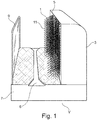
- FIG. 1 shows a side view of an embodiment of a device V according to the invention.
- the device V has a cleaning device 1, which is positioned in a housing 3 and in particular is fixed.
- a number, in particular two cleaning rollers 11, can be rotatably mounted vertically in the housing 3.
- the cleaning rollers 11 can be moved by means of electric motors arranged along the axes of rotation, within the cleaning rollers 11.
- the two cleaning rollers 11 can be rotated in any direction of rotation.
- the housing 3 has at least one open side 5.
- the housing 3 can additionally have a base, a cover, two end faces and, opposite the open side 5, a further side cover. In this way, the cleaning device 1 with the cleaning rollers is largely protected from external mechanical forces fixable in the housing 3.
- Access to the cleaning rollers 11 can be created from the open side 5.
- the housing 3 also acts as a protection, so that no cleaning agent is released from the cleaning device 1 into the environment, for example to a person.
- the bottom of the housing 3 is led out on the open side 5 from below the cleaning device 1 and in this way creates a receiving area 7 for carrying and positioning the object to be cleaned, in particular the bicycle Z.
- the receiving area 7 forms a guide channel 8, along the two-wheeler Z to be cleaned, which in Figures 2 and 3 is shown can be moved by a human. In this way, a certain distance between a two-wheeler Z to the cleaning rollers 11 is adjustable.
- the two-wheeler Z and the housing 3 can be arranged with respect to one another and the cleaning device 1 can act on the two-wheeler Z by means of the cleaning rollers 11 through the open side 5 and, for example, brush them off and / or apply a cleaning liquid.
- the cleaning device 1 can have a spray device and / or a drying device.
- a holding device 9 is fastened here at the end region of the floor there, in the form of a holding bracket, to which a person can hold, but to which a two-wheeler Z can also be leaned.
- the receiving area 7 can have a covering on the side of a two-wheeler Z that has a non-slip surface profile, so that it can offer a grip for a walking person. The covering can also repel a cleaning liquid and protect the device from wear.
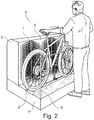
- Figure 2 shows a side view of the embodiment of the device V according to Figure 1 operational. It is shown how an operator moves a two-wheeler Z along the guide trough 8 into a relative and cleaning position to the cleaning rollers 11 of the cleaning device 1 fixed in the housing 3. Brush the cleaning rollers out of the open side 5 11 first a first side of the two-wheeler Z, which is placed on the receiving area 7.
- a holding bracket is fixed between the two-wheeler Z and the operator, which also distances the operator from the bicycle and protects it. The operator can hold the two-wheeler Z during cleaning and can also press the two-wheeler Z against the cleaning rollers with a selected force in order to enhance the cleaning effect.
- Figure 3 shows a further side view of the embodiment of the device V according to Figure 1 operational.
- the two-wheeler Z is now cleaned on its second side.
- Figure 3 shows that the operator alternatively Figure 2 can assume a further relative position to the two-wheeler Z and the device V during cleaning.
- the reference numeral 9 denotes a bracket which also protects against the two-wheeler Z to be cleaned.
- FIG. 4 shows an embodiment of the use of two devices V1 and V2 according to the invention.
- Devices V according to the invention are arranged in a row in a modular manner.
- the devices V1 and V2 are identical.
- devices V1 and V2 are arranged along their guide channels 8 and 8 '.
- the open side 5 of the first device V1 faces the open side 5 'of the second device V2.
- a two-wheeler Z moving along both guide channels 8 and 8 ' can be cleaned first on one side and then on the second side thereof without the two-wheeler Z having to be turned over and again guided past a single device V.
- Cleaning rollers 11 can be rotatably mounted horizontally, vertically and / or diagonally in a housing 3.
- FIG 5 shows a further side view of the embodiment of a device according to the invention Figure 1 now in a collapsed state.
- the receiving area 7 of the base and the area of the housing 3 containing the cleaning device 1 are placed on top of one another in such a way that the open side 5 is covered.
- the receiving area 7 can be mechanically connected to the area of the housing 3 containing the cleaning device 1.
- the housing 3 can be folded into the receiving area 7 and covered. In this position, the device can be releasably locked again by means of mechanical locks.
- the receiving area 7 of the floor and the area of the housing 3 containing the cleaning device 1 can be created in the form of a tub W or a shell or a box. The device can thus be handled in accordance with a suitcase.
- a handle can be arranged on the device V.
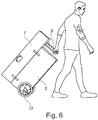
- Figure 6 shows a further view of the embodiment of a device according to the invention during transport.
- a person can grip and pull the device V on the bent rod or on the bracket 9, the device being able to be moved by means of transport rollers 13.
- the housing 3 has on its bottom on the side facing away from the open side 5 at least one transport roller 13 or at least one wheel.
- Figure 7 shows a further view of the embodiment of a device V according to the invention during transport.
- the device V can be easily accommodated in a trunk of a motor vehicle or passenger car and transported therein.
- the dimensions of the device V according to the invention are 1.44 m ⁇ 0.85 m ⁇ 0.55 m (W ⁇ H ⁇ D).
- the dimensions of the device V in the present case are 1.44 m ⁇ 0.85 m ⁇ 0.95 m.
- the weight of the device V here is approximately 80 kg.
- FIG 8 shows a further view of the embodiment of a device according to the invention.
- the device V for cleaning an object in particular a two-wheeler Z, has a housing 3 containing a cleaning device 1 with an open side 5, on which the object and the housing 3 can be positioned relative to one another and from which the cleaning device 1 can be provided to act on the object.
- a control device 4 for controlling the cleaning device 1 is assigned for the cleaning device 1.
- the cleaning device 1 has a rotatable nozzle cleaning head 6 for dispensing cleaning medium.
- the cleaning head 6 is arranged in a lower spatial area such that bicycle pedals are not touched. After adjustment, the cleaning head 6 can also be easily brought back into position.
- the cleaning head 6 sprays the water in the direction of an upper hemisphere into the air, for example, when rotating about a vertical axis. Due to the position between the cleaning brushes or cleaning rollers 11, this spatial area of the hemisphere is reduced towards the front to the object. When rotating around a vertical axis, spray jets can run from 0 ° to 90 ° to the vertical to the object.
- the supply of the cleaning medium here water
- the supply of the cleaning medium can be created by means of a pipeline.
- around 7L / min can be applied to a lower part of a two-wheeler to remove dirt from the pedals, chain and rear derailleur.
- the area of the housing 3 that contains the cleaning device 1 has, along the edge of its open side 5, toward the object blinds or brushes for collecting 12 cleaning medium, for example in the form of sprayed water. Such brushes can be 15 mm wide, for example.
- the area of the housing 3 which contains the cleaning device 1 is designed here in the form of a box.
- the height of a respective cleaning roller 11 can be approximately 760 mm. In this way, an adaptation to is advantageous handlebars at an average height of 800mm. Only the handlebars and saddle are not touched, unlike the tires and frame of an average bike. The dimensions are also advantageous for placing a device according to the invention in a mid-size combination car.
- a holding device 9 according to Figure 1 is additionally created here as protection against sprayed cleaning medium, for example in the form of a plastic disc, in particular as a transparent disc.
- the cleaning jet protective pane can be made of polyethylene PET, for example. This disc can cover the open side 5.
- the device can work without a fixed water connection. Water can be drawn from a container built into the device. Dirty water can be cleaned, for example, using three filter stages of 100 ⁇ m, 20 ⁇ m and 5 ⁇ m.
- the control device 4 is set such that the cleaning rollers 11, which can also be referred to as cleaning brushes, do not distribute any protection or water to the outside of the device V when rotating. If there is no bicycle in the device, the cleaning rollers 11 rotate "inwards", that is, the first counterclockwise and the second clockwise. If a bicycle is inserted, the cleaning rollers 11 detect this, since pressure is exerted on them and the electric motors have to increase the power and “draw” more electricity. The cleaning rollers 11 then rotate clockwise and counterclockwise for a few seconds each. In this way, the cleaning effect is effectively increased. Water losses are avoided and people are not polluted.
- the cleaning medium can be water or any known liquid agent. Additions are also possible.
- the control device 4 can have a microprocessor which can detect the currents of the electric motors and can output corresponding control signals for the directions of rotation and duration of rotation.
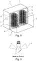
- Figure 9 shows a view of a conventional cleaning head.
- the cleaning head 6 can be rotated about a vertical axis here. It can spray out and / or spray out a cleaning medium, particularly advantageously water, and consist of stainless steel and here have three spray compartments which spray here into an area of an upper hemisphere.
- the cleaning head 6 is arranged between two cleaning rollers 11, so that the hemisphere of the spray can change in the form of a funnel. Continuous cleaning can be carried out by means of the cleaning head 6.
- the device V has a housing 3 with an open side 5.
- a receiving area 7 for receiving the object to be cleaned, in particular a two-wheeler.
- a guide channel 8 is arranged in the receiving area 7.
- the guide trough 8 is formed from a plurality of rollers 14.
- a ramp 15 is provided for entry into the guide trough 8, via which a two-wheeler can be guided into the receiving area 7.
- a plurality of cleaning heads 6 are arranged which spray the object to be cleaned in the receiving area 7 with cleaning medium.
- a cleaning head 6 is arranged such that it sprays the object from below.
- two cleaning heads 6 are arranged in the vertical direction on the inlet side of the cleaning rollers 11 and between the cleaning rollers 11.
- the receiving area 7 is delimited on the side opposite the open side 5 by a splash guard 21.
- a controller 4 is arranged on the housing 3.
- the device 1 can be supplied with energy by means of a solar panel 16 arranged on the cover of the device V.
- a prewash area 17 is arranged next to the receiving area 7 on the side of the device V.
- the device V has a modular structure.
- the device V is composed of the housing 3, the prewash area 17, the splash guard 21 and the receiving area 7.
- FIG. 13 The third exemplary embodiment of a device according to the invention shown shows a first device V1 and a second device V2, the open sides 5 and 5 'of which are arranged opposite each other. Such an arrangement can be achieved in a simple manner by the modular construction of the devices V1 and V2 according to the invention.
- the receiving area 7 is surrounded on two sides with cleaning rollers 11 and 11 'mounted in the vertical direction. Therefore, only a single pass through the receiving area 7 is necessary for cleaning the object.
- a prewash area 17 is additionally arranged on the device V2.
- a device V according to the invention each have transport rollers 13 arranged below the device V.
- the device V can thus be easily moved and transported.
- a bearing 18 for the storage of the cleaning rollers 11 is shown.
- the bearing 18 is arranged in a recess 22 provided for this purpose in a plate 24.
- the cleaning rollers 11 are connected in a rotationally fixed manner to a drum motor 20 by means of grub screws 19.
- the drum motor 20 is also mounted on the plate 24 by means of a threaded rod 26.
- a gap 28 is provided between the bearing 18 and the plate 24, through which the cleaning medium can pass from the cleaning rollers 11 without having a negative influence on the bearing.
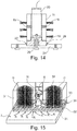
- FIG. 15 The device V according to the invention is shown with a filter area 30 arranged in the housing 3.
- the filter area 30 is arranged at a distance from the receiving area 7.
- Cleaning medium which was used for cleaning the object, runs along the arrows R below the cleaning rollers 11 through a grid-shaped structure 31 into the filter area 30.
- a filter mat 32 is arranged in the filter area 30.
- loosely poured filter material 33 in the form of filter balls is arranged above the filter mat 32.
- the soiled cleaning medium is pumped through the filter area 30 by means of a pump 34 and pumped into a filter cartridge 35.
- a cleaning head 6 is arranged downstream of the filter cartridge 35, to which the cleaning medium passes after passing through the filter area 30 and the filter cartridge 35.
- the filter area 30 is preferably arranged below the cleaning rollers 11.
- the filter area 30 is preferably sealed off from the rollers 11, so that no unfiltered, dirty cleaning medium can reach the rollers 11.
- the cleaning medium is, for example, in the recording area 7 and sucked into the filter area 30 through openings (arrows R).
- Fig. 16 the filter area 30 is shown.
- the dirty cleaning medium flows through openings in the filter area 30 at the lower edge and is sucked by the pump 34 first through a filter mat 32 with coarse filter material, then through a filter mat 32 with fine filter material and then through loosely poured filter material 33.
- the loosely poured filter material 33 is constructed, for example, from filter balls (eg Aqualoon®), which are also preferably arranged in a network. As a result, the filter balls can easily be removed from the filter area 30 or replaced.
- the flow path can be defined, for example, by Z partition walls 36, so that the cleaning medium to be filtered is diverted through these Z partition walls 36 and supplied to the pump 34.
- FIG. 17 A fifth exemplary embodiment of a device V according to the invention is shown.
- the device comprises a housing 3 which, viewed in the longitudinal direction, has an opening 38 in the form of a receiving area 7.
- a cleaning roller 11 is arranged on the housing 3 on the left and right of the receiving area 7.
- the filter area 30 extends below the cleaning rollers 11.
- a ramp 15 is provided which merges into a guide trough 8 with rollers 14.
- the housing 3 shown in this fifth exemplary embodiment has the same extent as a housing 3 shown in the previous exemplary embodiments. In this case, the object is not guided past the length of the housing 3, but is guided through the opening 38 through the receiving area 7. which extends transversely to the longitudinal direction of the housing 3.
Landscapes
- Engineering & Computer Science (AREA)
- Mechanical Engineering (AREA)
- Cleaning In General (AREA)
- Cleaning By Liquid Or Steam (AREA)
Claims (14)
- Appareil (V) de nettoyage d'un objet, en particulier d'une bicyclette (Z), dans lequel un boîtier (3) contenant un dispositif de nettoyage (1) est muni d'un côté ouvert (5) au niveau duquel l'objet et le boîtier (3) peuvent être positionnés l'un par rapport à l'autre et à partir duquel le dispositif de nettoyage (1) peut être fourni de manière à agir sur l'objet, dans lequel le dispositif de nettoyage (1) présente un dispositif de commande (4) destiné à la commande du dispositif de nettoyage (1), caractérisé en ce que le dispositif de nettoyage (1) présente deux rouleaux de nettoyage (11) de type brosse rotatifs au moyen d'un ou de plusieurs moteur(s) électrique(s),
dans lequel le dispositif de commande (4) est conçu pour faire tourner les rouleaux de nettoyage (11) dans des sens de rotation opposés dans un premier mode de fonctionnement. - Appareil (V) selon la revendication 1, caractérisé en ce que le dispositif de nettoyage (1) présente, sur le côté ouvert (5) dans une zone intermédiaire entre les deux rouleaux de nettoyage rotatifs, une tête de nettoyage rotative à buses (6) destinée à l'application d'un produit de nettoyage.
- Appareil (V) selon l'une quelconque des revendications précédentes, caractérisé en ce que la région, contenant le dispositif de nettoyage (1), du boîtier (3) présente, le long du bord du côté ouvert (5) de celui-ci et en direction de l'objet, des écrans ou des brosses destiné(e)s à la collecte (12) du produit de nettoyage.
- Appareil (V) selon l'une quelconque des revendications précédentes, caractérisé en ce que le dispositif de commande (4) est conçu de telle manière que, dans le premier mode de fonctionnement, un premier des rouleaux de nettoyage, vu du dessus, tourne dans le sens contraire des aiguilles d'une montre et un second des rouleaux de nettoyage, vu du dessus, tourne dans le sens des aiguilles d'une montre.
- Appareil (V) selon l'une quelconque des revendications précédentes, caractérisé en ce que, dans un second mode de fonctionnement, le dispositif de commande (4) est conçu pour faire tourner les rouleaux de nettoyage (11) respectivement de manière alternée pendant une période de temps de l'ordre de quelques secondes dans le sens des aiguilles d'une montre et dans le sens inverse des aiguilles d'une montre.
- Appareil (V) selon l'une quelconque des revendications précédentes, caractérisé en ce que le dispositif de commande (4) est conçu pour passer du premier mode de fonctionnement au second mode de fonctionnement dès lors que l'objet à nettoyer est pressé contre les rouleaux de nettoyage (11) et qu'ainsi la puissance électromotrice nécessaire s'accroît.
- Appareil (V) selon l'une quelconque des revendications précédentes, caractérisé en ce que le dispositif de commande (4) est conçu pour passer du deuxième mode de fonctionnement au premier mode de fonctionnement dès lors que l'objet à nettoyer est éloigné des rouleaux de nettoyage (11) et qu'ainsi la puissance électromotrice nécessaire décroît.
- Appareil (V) selon l'une quelconque des revendications précédentes, caractérisé en ce que le dispositif de commande (4) est conçu pour mettre hors tension de manière à nouveau commutable les rouleaux de nettoyage (11) et/ou l'appareil lorsqu'une valeur limite de pression contre les rouleaux de nettoyage (11) est dépassée.
- Appareil (V) selon l'une quelconque des revendications précédentes 2 à 8, caractérisé en ce qu'un circuit présentant récipient et filtre et faisant circuler le produit de nettoyage, en particulier de l'eau, est réalisé à l'intérieur du dispositif.
- Appareil (V) selon l'une quelconque des revendications précédentes, caractérisé en ce qu'une région de prélavage (17) est agencée à distance du côté ouvert (5).
- Appareil (V) selon l'une quelconque des revendications précédentes, caractérisé en ce que l'objet à nettoyer est guidé à travers l'appareil (V) dans une coulisse de guidage (8), dans lequel la coulisse de guidage (8) est formée grâce à des galets (14).
- Appareil (V) selon l'une quelconque des revendications précédentes, caractérisé en ce qu'un panneau solaire (16) est agencé au niveau du boîtier (3).
- Appareil (V) selon l'une quelconque des revendications précédentes, caractérisé en ce que le boîtier (3) et le dispositif de nettoyage (1) sont reliés l'un à l'autre de manière amovible.
- Appareil (V) selon l'une quelconque des revendications précédentes, caractérisé en ce qu'une région de filtrage (30) est agencée dans le boîtier (3), dans lequel la région de filtrage comprend au moins un tapis de filtrage (32), ainsi qu'un remplissage en vrac de matériau de filtrage (33) agencé par-dessus dans le sens de la hauteur, dans lequel une pompe (34) pompe du produit de nettoyage dans au moins une cartouche de filtrage (35) à travers le au moins un tapis de filtrage(32) et le remplissage en vrac de matériau de filtrage (33).
Priority Applications (1)
| Application Number | Priority Date | Filing Date | Title |
|---|---|---|---|
| PL16797759T PL3368384T3 (pl) | 2015-10-28 | 2016-10-26 | Urządzenie do czyszczenia obiektów, w szczególności pojazdów dwukołowych |
Applications Claiming Priority (4)
| Application Number | Priority Date | Filing Date | Title |
|---|---|---|---|
| DE102015118371 | 2015-10-28 | ||
| DE202016102020.4U DE202016102020U1 (de) | 2015-10-28 | 2016-04-16 | Vorrichtung zur Reinigung von Objekten, insbesondere Zweirädern |
| DE102016111486.3A DE102016111486A1 (de) | 2015-10-28 | 2016-06-22 | Vorrichtung zum Reinigen von Objekten, insbesondere Zweirädern |
| PCT/EP2016/075785 WO2017072167A1 (fr) | 2015-10-28 | 2016-10-26 | Dispositif servant à nettoyer des objets, en particulier des deux-roues |
Publications (2)
| Publication Number | Publication Date |
|---|---|
| EP3368384A1 EP3368384A1 (fr) | 2018-09-05 |
| EP3368384B1 true EP3368384B1 (fr) | 2020-01-08 |
Family
ID=56233620
Family Applications (1)
| Application Number | Title | Priority Date | Filing Date |
|---|---|---|---|
| EP16797759.4A Active EP3368384B1 (fr) | 2015-10-28 | 2016-10-26 | Dispositif servant à nettoyer des objets, en particulier des deux-roues |
Country Status (7)
| Country | Link |
|---|---|
| US (1) | US20200361425A1 (fr) |
| EP (1) | EP3368384B1 (fr) |
| CN (1) | CN108473113B (fr) |
| DE (2) | DE202016102020U1 (fr) |
| DK (1) | DK3368384T3 (fr) |
| ES (1) | ES2782209T3 (fr) |
| PL (1) | PL3368384T3 (fr) |
Families Citing this family (4)
| Publication number | Priority date | Publication date | Assignee | Title |
|---|---|---|---|---|
| US11229930B2 (en) * | 2016-02-18 | 2022-01-25 | Jeanneworks, Inc. | Washing system and methods of use |
| CN110090829B (zh) * | 2019-06-06 | 2024-05-17 | 深圳市思力铭科技有限公司 | 一种通道式车轮清洗装置 |
| DE102020134327A1 (de) | 2020-12-20 | 2022-06-23 | Sachin Kumar | Vorrichtung und Verfahren zur Reinigung von Zweirädern |
| CN113696857A (zh) * | 2021-09-12 | 2021-11-26 | 郝洋 | 一种共享单车推进清洁器 |
Family Cites Families (8)
| Publication number | Priority date | Publication date | Assignee | Title |
|---|---|---|---|---|
| FR2581947B1 (fr) * | 1985-05-15 | 1987-08-07 | Axiome Ste Civile | Installation pour le nettoyage et le lavage de vehicules a deux roues |
| DE9208442U1 (de) * | 1992-06-24 | 1992-08-13 | Simhart, Christine, 8000 München | Fahrradputzbox |
| DE4325973C1 (de) * | 1993-08-03 | 1994-10-20 | Walter Hochmuth | Vorrichtung zum Reinigen eines Zweirades, insbesondere eines Fahrrades |
| DE29505047U1 (de) * | 1995-03-24 | 1995-06-22 | Ostheimer, Thomas, 76131 Karlsruhe | Vorrichtung zur vollautomatischen Reinigung eines Fahrrades |
| DE29506873U1 (de) * | 1995-04-24 | 1995-06-22 | Hochmuth, Walter, 90431 Nürnberg | Vorrichtung zum Reinigen eines Zweirads |
| CN2866268Y (zh) * | 2005-12-05 | 2007-02-07 | 黄明歆 | 全自动电脑摩托车清洗器 |
| FR2976539B1 (fr) * | 2011-06-17 | 2013-06-21 | Matondo Wansulama | Dispositif compose d'un portique muni de bras mobiles et morpho adaptables aux contours d'un element, et une plateforme coulissante le prenant en charge et le maintenant en equilibre. |
| FR3025162B1 (fr) * | 2014-08-29 | 2016-09-09 | Serrurier Projets Brevets | Tunnel de lavage pour motos |
-
2016
- 2016-04-16 DE DE202016102020.4U patent/DE202016102020U1/de not_active Expired - Lifetime
- 2016-06-22 DE DE102016111486.3A patent/DE102016111486A1/de not_active Withdrawn
- 2016-10-26 PL PL16797759T patent/PL3368384T3/pl unknown
- 2016-10-26 US US15/779,471 patent/US20200361425A1/en not_active Abandoned
- 2016-10-26 EP EP16797759.4A patent/EP3368384B1/fr active Active
- 2016-10-26 CN CN201680076166.9A patent/CN108473113B/zh active Active
- 2016-10-26 ES ES16797759T patent/ES2782209T3/es active Active
- 2016-10-26 DK DK16797759.4T patent/DK3368384T3/da active
Non-Patent Citations (1)
| Title |
|---|
| None * |
Also Published As
| Publication number | Publication date |
|---|---|
| EP3368384A1 (fr) | 2018-09-05 |
| PL3368384T3 (pl) | 2020-06-29 |
| CN108473113A (zh) | 2018-08-31 |
| US20200361425A1 (en) | 2020-11-19 |
| ES2782209T3 (es) | 2020-09-11 |
| DK3368384T3 (da) | 2020-03-16 |
| CN108473113B (zh) | 2021-06-08 |
| DE202016102020U1 (de) | 2016-06-06 |
| DE102016111486A1 (de) | 2017-05-04 |
Similar Documents
| Publication | Publication Date | Title |
|---|---|---|
| EP3368384B1 (fr) | Dispositif servant à nettoyer des objets, en particulier des deux-roues | |
| DE69801545T2 (de) | Bodenscheuermaschine mit einer Vorrichtung zum kontinuierlichenReinigen eines Filters | |
| DE102009006146A1 (de) | Fahrbare HD-Reinigungsmaschine für Outdoor-Kunststoffböden, und deren Anwendung | |
| DE69514597T2 (de) | Portalrahmen und Verfahren zum Waschen von Fahrzeugen | |
| WO2017072167A1 (fr) | Dispositif servant à nettoyer des objets, en particulier des deux-roues | |
| WO2013004794A1 (fr) | Dispositif de nettoyage de véhicules à deux roues | |
| EP3947060B1 (fr) | Dispositif de lavage et d'entretien pour véhicule à roues avec séparation du liquide de lavage et du produit d'entretien | |
| DE9112116U1 (de) | Automatische Zweiradreinigungseinrichtung | |
| EP3817954B1 (fr) | Arrangement de nettoyage de véhicules à deux roues | |
| DE102016002922A1 (de) | Neue Reinigungsvorrichtung und Verfahren zur Reinigung | |
| DE202016001593U1 (de) | Neue Reinigungsvorrichtung | |
| DE19824271A1 (de) | Waschanlage zum automatischen Naßreinigen von sperrigen Gegenständen, insbesondere Zweirädern in einem Waschvorgang | |
| DE102018102739B4 (de) | Vorrichtung und Verfahren zur Reinigung von Rädern eines Mobilitätshilfsmittels | |
| DE29909258U1 (de) | Waschvorrichtung für Autofußmatten aus vorzugsweise gummiartigem Material | |
| DE19527828C2 (de) | Verfahren und Vorrichtung zum Waschen von Fahrzeugen | |
| DE19822537A1 (de) | Reinigungsvorrichtung für Karosserien von Fahrzeugen | |
| DE102008042119B4 (de) | Portalwaschanlage für Kraftfahrzeuge | |
| EP3966077B1 (fr) | Appareil et methode pour nettoyer des objets, en particulier des deux-roues | |
| AT402477B (de) | Verfahren zum reinigen einer vliesartigen filtermatte | |
| EP3372286B1 (fr) | Station de nettoyage notamment pour un chariot de golf | |
| DE1023985B (de) | Vorrichtung zum Reinigen von Zweiraedern | |
| DE202024101420U1 (de) | Fahrradwaschanlage | |
| DE9114923U1 (de) | Mechanische Fahrzeugwaschanlage | |
| DE202012006082U1 (de) | Kraftfahrzeug-Waschstraße | |
| DE1992710U (de) | Staubabsaughaube bzw. -kabine mit angebautem taschenfilter. |
Legal Events
| Date | Code | Title | Description |
|---|---|---|---|
| STAA | Information on the status of an ep patent application or granted ep patent |
Free format text: STATUS: UNKNOWN |
|
| STAA | Information on the status of an ep patent application or granted ep patent |
Free format text: STATUS: THE INTERNATIONAL PUBLICATION HAS BEEN MADE |
|
| PUAI | Public reference made under article 153(3) epc to a published international application that has entered the european phase |
Free format text: ORIGINAL CODE: 0009012 |
|
| STAA | Information on the status of an ep patent application or granted ep patent |
Free format text: STATUS: REQUEST FOR EXAMINATION WAS MADE |
|
| 17P | Request for examination filed |
Effective date: 20180524 |
|
| AK | Designated contracting states |
Kind code of ref document: A1 Designated state(s): AL AT BE BG CH CY CZ DE DK EE ES FI FR GB GR HR HU IE IS IT LI LT LU LV MC MK MT NL NO PL PT RO RS SE SI SK SM TR |
|
| AX | Request for extension of the european patent |
Extension state: BA ME |
|
| DAV | Request for validation of the european patent (deleted) | ||
| DAX | Request for extension of the european patent (deleted) | ||
| GRAP | Despatch of communication of intention to grant a patent |
Free format text: ORIGINAL CODE: EPIDOSNIGR1 |
|
| STAA | Information on the status of an ep patent application or granted ep patent |
Free format text: STATUS: GRANT OF PATENT IS INTENDED |
|
| INTG | Intention to grant announced |
Effective date: 20190913 |
|
| GRAS | Grant fee paid |
Free format text: ORIGINAL CODE: EPIDOSNIGR3 |
|
| GRAA | (expected) grant |
Free format text: ORIGINAL CODE: 0009210 |
|
| STAA | Information on the status of an ep patent application or granted ep patent |
Free format text: STATUS: THE PATENT HAS BEEN GRANTED |
|
| AK | Designated contracting states |
Kind code of ref document: B1 Designated state(s): AL AT BE BG CH CY CZ DE DK EE ES FI FR GB GR HR HU IE IS IT LI LT LU LV MC MK MT NL NO PL PT RO RS SE SI SK SM TR |
|
| REG | Reference to a national code |
Ref country code: GB Ref legal event code: FG4D Free format text: NOT ENGLISH |
|
| REG | Reference to a national code |
Ref country code: CH Ref legal event code: EP |
|
| REG | Reference to a national code |
Ref country code: DE Ref legal event code: R096 Ref document number: 502016008378 Country of ref document: DE |
|
| REG | Reference to a national code |
Ref country code: IE Ref legal event code: FG4D Free format text: LANGUAGE OF EP DOCUMENT: GERMAN |
|
| REG | Reference to a national code |
Ref country code: AT Ref legal event code: REF Ref document number: 1222307 Country of ref document: AT Kind code of ref document: T Effective date: 20200215 |
|
| REG | Reference to a national code |
Ref country code: SE Ref legal event code: TRGR |
|
| REG | Reference to a national code |
Ref country code: DK Ref legal event code: T3 Effective date: 20200310 |
|
| REG | Reference to a national code |
Ref country code: NL Ref legal event code: FP |
|
| REG | Reference to a national code |
Ref country code: CH Ref legal event code: NV Representative=s name: SIVIER, CONSEIL EN BREVETS EUROPEENS, CH |
|
| REG | Reference to a national code |
Ref country code: NO Ref legal event code: T2 Effective date: 20200108 |
|
| REG | Reference to a national code |
Ref country code: LT Ref legal event code: MG4D |
|
| PG25 | Lapsed in a contracting state [announced via postgrant information from national office to epo] |
Ref country code: RS Free format text: LAPSE BECAUSE OF FAILURE TO SUBMIT A TRANSLATION OF THE DESCRIPTION OR TO PAY THE FEE WITHIN THE PRESCRIBED TIME-LIMIT Effective date: 20200108 Ref country code: PT Free format text: LAPSE BECAUSE OF FAILURE TO SUBMIT A TRANSLATION OF THE DESCRIPTION OR TO PAY THE FEE WITHIN THE PRESCRIBED TIME-LIMIT Effective date: 20200531 Ref country code: FI Free format text: LAPSE BECAUSE OF FAILURE TO SUBMIT A TRANSLATION OF THE DESCRIPTION OR TO PAY THE FEE WITHIN THE PRESCRIBED TIME-LIMIT Effective date: 20200108 Ref country code: LT Free format text: LAPSE BECAUSE OF FAILURE TO SUBMIT A TRANSLATION OF THE DESCRIPTION OR TO PAY THE FEE WITHIN THE PRESCRIBED TIME-LIMIT Effective date: 20200108 |
|
| PG25 | Lapsed in a contracting state [announced via postgrant information from national office to epo] |
Ref country code: LV Free format text: LAPSE BECAUSE OF FAILURE TO SUBMIT A TRANSLATION OF THE DESCRIPTION OR TO PAY THE FEE WITHIN THE PRESCRIBED TIME-LIMIT Effective date: 20200108 Ref country code: HR Free format text: LAPSE BECAUSE OF FAILURE TO SUBMIT A TRANSLATION OF THE DESCRIPTION OR TO PAY THE FEE WITHIN THE PRESCRIBED TIME-LIMIT Effective date: 20200108 Ref country code: BG Free format text: LAPSE BECAUSE OF FAILURE TO SUBMIT A TRANSLATION OF THE DESCRIPTION OR TO PAY THE FEE WITHIN THE PRESCRIBED TIME-LIMIT Effective date: 20200408 Ref country code: IS Free format text: LAPSE BECAUSE OF FAILURE TO SUBMIT A TRANSLATION OF THE DESCRIPTION OR TO PAY THE FEE WITHIN THE PRESCRIBED TIME-LIMIT Effective date: 20200508 Ref country code: GR Free format text: LAPSE BECAUSE OF FAILURE TO SUBMIT A TRANSLATION OF THE DESCRIPTION OR TO PAY THE FEE WITHIN THE PRESCRIBED TIME-LIMIT Effective date: 20200409 |
|
| REG | Reference to a national code |
Ref country code: ES Ref legal event code: FG2A Ref document number: 2782209 Country of ref document: ES Kind code of ref document: T3 Effective date: 20200911 |
|
| REG | Reference to a national code |
Ref country code: DE Ref legal event code: R097 Ref document number: 502016008378 Country of ref document: DE |
|
| PG25 | Lapsed in a contracting state [announced via postgrant information from national office to epo] |
Ref country code: SK Free format text: LAPSE BECAUSE OF FAILURE TO SUBMIT A TRANSLATION OF THE DESCRIPTION OR TO PAY THE FEE WITHIN THE PRESCRIBED TIME-LIMIT Effective date: 20200108 Ref country code: RO Free format text: LAPSE BECAUSE OF FAILURE TO SUBMIT A TRANSLATION OF THE DESCRIPTION OR TO PAY THE FEE WITHIN THE PRESCRIBED TIME-LIMIT Effective date: 20200108 Ref country code: CZ Free format text: LAPSE BECAUSE OF FAILURE TO SUBMIT A TRANSLATION OF THE DESCRIPTION OR TO PAY THE FEE WITHIN THE PRESCRIBED TIME-LIMIT Effective date: 20200108 Ref country code: EE Free format text: LAPSE BECAUSE OF FAILURE TO SUBMIT A TRANSLATION OF THE DESCRIPTION OR TO PAY THE FEE WITHIN THE PRESCRIBED TIME-LIMIT Effective date: 20200108 Ref country code: SM Free format text: LAPSE BECAUSE OF FAILURE TO SUBMIT A TRANSLATION OF THE DESCRIPTION OR TO PAY THE FEE WITHIN THE PRESCRIBED TIME-LIMIT Effective date: 20200108 |
|
| PLBE | No opposition filed within time limit |
Free format text: ORIGINAL CODE: 0009261 |
|
| STAA | Information on the status of an ep patent application or granted ep patent |
Free format text: STATUS: NO OPPOSITION FILED WITHIN TIME LIMIT |
|
| 26N | No opposition filed |
Effective date: 20201009 |
|
| PG25 | Lapsed in a contracting state [announced via postgrant information from national office to epo] |
Ref country code: SI Free format text: LAPSE BECAUSE OF FAILURE TO SUBMIT A TRANSLATION OF THE DESCRIPTION OR TO PAY THE FEE WITHIN THE PRESCRIBED TIME-LIMIT Effective date: 20200108 |
|
| PG25 | Lapsed in a contracting state [announced via postgrant information from national office to epo] |
Ref country code: MC Free format text: LAPSE BECAUSE OF FAILURE TO SUBMIT A TRANSLATION OF THE DESCRIPTION OR TO PAY THE FEE WITHIN THE PRESCRIBED TIME-LIMIT Effective date: 20200108 Ref country code: LU Free format text: LAPSE BECAUSE OF NON-PAYMENT OF DUE FEES Effective date: 20201026 |
|
| PG25 | Lapsed in a contracting state [announced via postgrant information from national office to epo] |
Ref country code: TR Free format text: LAPSE BECAUSE OF FAILURE TO SUBMIT A TRANSLATION OF THE DESCRIPTION OR TO PAY THE FEE WITHIN THE PRESCRIBED TIME-LIMIT Effective date: 20200108 Ref country code: MT Free format text: LAPSE BECAUSE OF FAILURE TO SUBMIT A TRANSLATION OF THE DESCRIPTION OR TO PAY THE FEE WITHIN THE PRESCRIBED TIME-LIMIT Effective date: 20200108 Ref country code: CY Free format text: LAPSE BECAUSE OF FAILURE TO SUBMIT A TRANSLATION OF THE DESCRIPTION OR TO PAY THE FEE WITHIN THE PRESCRIBED TIME-LIMIT Effective date: 20200108 |
|
| PG25 | Lapsed in a contracting state [announced via postgrant information from national office to epo] |
Ref country code: MK Free format text: LAPSE BECAUSE OF FAILURE TO SUBMIT A TRANSLATION OF THE DESCRIPTION OR TO PAY THE FEE WITHIN THE PRESCRIBED TIME-LIMIT Effective date: 20200108 Ref country code: AL Free format text: LAPSE BECAUSE OF FAILURE TO SUBMIT A TRANSLATION OF THE DESCRIPTION OR TO PAY THE FEE WITHIN THE PRESCRIBED TIME-LIMIT Effective date: 20200108 |
|
| PGFP | Annual fee paid to national office [announced via postgrant information from national office to epo] |
Ref country code: SE Payment date: 20231025 Year of fee payment: 8 Ref country code: NO Payment date: 20231023 Year of fee payment: 8 Ref country code: IE Payment date: 20231019 Year of fee payment: 8 Ref country code: DK Payment date: 20231025 Year of fee payment: 8 |
|
| REG | Reference to a national code |
Ref country code: DE Ref legal event code: R082 Ref document number: 502016008378 Country of ref document: DE Representative=s name: BOEHMERT & BOEHMERT ANWALTSPARTNERSCHAFT MBB -, DE |
|
| REG | Reference to a national code |
Ref country code: DE Ref legal event code: R082 Ref document number: 502016008378 Country of ref document: DE Representative=s name: BOEHMERT & BOEHMERT ANWALTSPARTNERSCHAFT MBB -, DE |
|
| REG | Reference to a national code |
Ref country code: DK Ref legal event code: EBP Effective date: 20241031 |
|
| REG | Reference to a national code |
Ref country code: SE Ref legal event code: EUG |
|
| PG25 | Lapsed in a contracting state [announced via postgrant information from national office to epo] |
Ref country code: NO Free format text: LAPSE BECAUSE OF NON-PAYMENT OF DUE FEES Effective date: 20241031 |
|
| PG25 | Lapsed in a contracting state [announced via postgrant information from national office to epo] |
Ref country code: DK Free format text: LAPSE BECAUSE OF NON-PAYMENT OF DUE FEES Effective date: 20241031 |
|
| PG25 | Lapsed in a contracting state [announced via postgrant information from national office to epo] |
Ref country code: SE Free format text: LAPSE BECAUSE OF NON-PAYMENT OF DUE FEES Effective date: 20241027 |
|
| PGFP | Annual fee paid to national office [announced via postgrant information from national office to epo] |
Ref country code: PL Payment date: 20250930 Year of fee payment: 10 |
|
| PG25 | Lapsed in a contracting state [announced via postgrant information from national office to epo] |
Ref country code: IE Free format text: LAPSE BECAUSE OF NON-PAYMENT OF DUE FEES Effective date: 20241026 |
|
| REG | Reference to a national code |
Ref country code: CH Ref legal event code: U11 Free format text: ST27 STATUS EVENT CODE: U-0-0-U10-U11 (AS PROVIDED BY THE NATIONAL OFFICE) Effective date: 20251101 |
|
| PGFP | Annual fee paid to national office [announced via postgrant information from national office to epo] |
Ref country code: NL Payment date: 20251024 Year of fee payment: 10 |
|
| PGFP | Annual fee paid to national office [announced via postgrant information from national office to epo] |
Ref country code: DE Payment date: 20251028 Year of fee payment: 10 |
|
| PGFP | Annual fee paid to national office [announced via postgrant information from national office to epo] |
Ref country code: GB Payment date: 20251023 Year of fee payment: 10 |
|
| PGFP | Annual fee paid to national office [announced via postgrant information from national office to epo] |
Ref country code: AT Payment date: 20251020 Year of fee payment: 10 |
|
| PGFP | Annual fee paid to national office [announced via postgrant information from national office to epo] |
Ref country code: IT Payment date: 20251022 Year of fee payment: 10 |
|
| PGFP | Annual fee paid to national office [announced via postgrant information from national office to epo] |
Ref country code: FR Payment date: 20251027 Year of fee payment: 10 |
|
| PGFP | Annual fee paid to national office [announced via postgrant information from national office to epo] |
Ref country code: BE Payment date: 20251024 Year of fee payment: 10 |
|
| PGFP | Annual fee paid to national office [announced via postgrant information from national office to epo] |
Ref country code: CH Payment date: 20251101 Year of fee payment: 10 |
|
| PGFP | Annual fee paid to national office [announced via postgrant information from national office to epo] |
Ref country code: ES Payment date: 20251118 Year of fee payment: 10 |