EP3368403B1 - Ancre ayant des propriétés de pénétration améliorées - Google Patents
Ancre ayant des propriétés de pénétration améliorées Download PDFInfo
- Publication number
- EP3368403B1 EP3368403B1 EP16782317.8A EP16782317A EP3368403B1 EP 3368403 B1 EP3368403 B1 EP 3368403B1 EP 16782317 A EP16782317 A EP 16782317A EP 3368403 B1 EP3368403 B1 EP 3368403B1
- Authority
- EP
- European Patent Office
- Prior art keywords
- plane
- anchor
- plates
- penetration
- shank
- Prior art date
- Legal status (The legal status is an assumption and is not a legal conclusion. Google has not performed a legal analysis and makes no representation as to the accuracy of the status listed.)
- Active
Links
Images


Classifications
-
- B—PERFORMING OPERATIONS; TRANSPORTING
- B63—SHIPS OR OTHER WATERBORNE VESSELS; RELATED EQUIPMENT
- B63B—SHIPS OR OTHER WATERBORNE VESSELS; EQUIPMENT FOR SHIPPING
- B63B21/00—Tying-up; Shifting, towing, or pushing equipment; Anchoring
- B63B21/24—Anchors
- B63B21/30—Anchors rigid when in use
- B63B21/34—Anchors rigid when in use with two or more flukes
-
- B—PERFORMING OPERATIONS; TRANSPORTING
- B63—SHIPS OR OTHER WATERBORNE VESSELS; RELATED EQUIPMENT
- B63B—SHIPS OR OTHER WATERBORNE VESSELS; EQUIPMENT FOR SHIPPING
- B63B21/00—Tying-up; Shifting, towing, or pushing equipment; Anchoring
- B63B21/24—Anchors
- B63B21/26—Anchors securing to bed
-
- B—PERFORMING OPERATIONS; TRANSPORTING
- B63—SHIPS OR OTHER WATERBORNE VESSELS; RELATED EQUIPMENT
- B63B—SHIPS OR OTHER WATERBORNE VESSELS; EQUIPMENT FOR SHIPPING
- B63B21/00—Tying-up; Shifting, towing, or pushing equipment; Anchoring
- B63B21/24—Anchors
- B63B21/30—Anchors rigid when in use
- B63B21/32—Anchors rigid when in use with one fluke
-
- B—PERFORMING OPERATIONS; TRANSPORTING
- B63—SHIPS OR OTHER WATERBORNE VESSELS; RELATED EQUIPMENT
- B63B—SHIPS OR OTHER WATERBORNE VESSELS; EQUIPMENT FOR SHIPPING
- B63B21/00—Tying-up; Shifting, towing, or pushing equipment; Anchoring
- B63B21/24—Anchors
- B63B21/26—Anchors securing to bed
- B63B2021/262—Anchors securing to bed by drag embedment
-
- B—PERFORMING OPERATIONS; TRANSPORTING
- B63—SHIPS OR OTHER WATERBORNE VESSELS; RELATED EQUIPMENT
- B63B—SHIPS OR OTHER WATERBORNE VESSELS; EQUIPMENT FOR SHIPPING
- B63B21/00—Tying-up; Shifting, towing, or pushing equipment; Anchoring
- B63B21/50—Anchoring arrangements or methods for special vessels, e.g. for floating drilling platforms or dredgers
Definitions
- the invention relates to an anchor comprising a fluke, a shank having two shank legs that are connected to the fluke, and a coupling to attach the shank to an anchor line or anchor chain.
- anchors are used for heavy maritime or offshore objects, such as a drilling platform. There is a continuous need for anchors for heavy maritime applications that stably penetrate the anchoring ground and provide a constant holding capacity during its use.
- AU2005200544 discloses an anchor with two shank legs according to the preamble of claim 1.
- the invention provides an anchor comprising a fluke, a shank that is connected to the fluke, and a coupling to attach the shank to an anchor line or anchor chain
- the shank comprises two shank legs each having a straight shank plate with an outer surface that extend on the opposite sides of the plane of symmetry of the anchor and that diverge from the coupling towards the fluke
- the fluke comprises two straight penetration plates with a top surface on the opposite sides of the plane of symmetry of the anchor, wherein the penetration plates are under an angle to each other, wherein the penetration plates extend outwards from the shank legs and obliquely downwards with respect to the direction from the coupling towards the fluke, wherein the top surfaces or the notional extensions thereof intersect each other along a notional straight datum line that extends in the plane of symmetry, wherein a notional datum plane is defined that extends perpendicular to the plane of symmetry and that intersects the plane of symmetry of the anchor along the datum line, wherein for the shank plates a not
- the anchor having the geometry as specified within the combined three small ranges for the first angle, the second angle and the third angle provides excellent penetration properties.
- the specified anchor stably penetrates the anchoring ground without intermediate breakouts in its penetration trajectory, leading to an excellent holding capacity during its use.
- the penetration plates extend on both sides of its nearest shank leg, having the top surface on both sides of that shank leg in the same plane. These top surfaces between the shank legs under the same specified third angle provide additional penetration capacity and holding capacity during the use of the anchor.
- the penetration plates each comprise an inner penetration edge and an outer penetration edge, wherein the penetration edges converge towards two penetration tips of the fluke to induce fast initial penetration of the fluke into the anchoring ground.
- the coupling extends in the projection perpendicular to the datum plane beyond the penetration tips of the fluke.
- the fluke comprises two girders extending below and connected to the penetration plates, wherein the shank legs are connected with the girders.
- the girders transfer the high penetration forces that are exerted to the shank to the penetration plates.
- the penetration tips are located at a distal end of the girders.
- the girders extend parallel to the plane of symmetry, whereby they can contribute in maintaining the anchor on it stable track during the penetration into the anchoring ground.
- the shank legs each comprise a straight middle section with the straight shank plates between the coupling and the fluke, and a base section with a base plate that is oriented under an angle with respect to the shank plates via a deflection line, wherein the main planes of the base plates and the girders extend parallel to or in line with each other.
- the shank legs comprise an end eye at the coupling, wherein the end eye comprises an eye plate that is under an angle with respect to the shank plates via a deflection line, wherein the eye plates extend parallel to each other.
- the fluke comprises reinforcement plates below the penetration plates that are connected to each other along their edges to form a rigid hollow box.
- the invention further relates to a computer-readable medium having computer-executable instructions adapted to cause a 3D printer to print an anchor according to the invention.
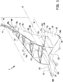
- FIGS 1-5 show an anchor 1 according to an embodiment of the invention.
- the anchor 1 is intended for anchoring heavy maritime or offshore objects, such as a drilling platform in a subsea anchoring ground, for a long period of use that may last many years.
- the anchor 1 has a typical deadweight of 1-50 tons.
- the anchor 1 comprises a fluke 10 and a shank 70 which with respect to the fluke 10 inclines obliquely forward and which at its end is provided with a shackle 90 by which the anchor 1 is connected to an anchor line or anchor chain 4.
- the anchor 1 is substantially symmetrical with respect to its plane of symmetry M.
- the anchor 1 is formed for in a forward penetration direction P being introduced into the anchoring ground substantially parallel to the plane of symmetry M.
- the fluke 10 is a hollow box built up using steel plate members that are connected to each other by welding. As best shown in figure 1 the fluke 10 comprises two straight penetration plates 11, 12 that are oriented obliquely with respect to the plane of symmetry M. The straight top surfaces 13 of the penetration plates 11, 12 that are directed towards the shank 70, or the notional extensions thereof outside the penetration plates 11, 12, intersect each other along a notional straight reference line or datum line Q that extends in the plane of symmetry M.
- a notional datum plane N is defined for the anchor 1.
- the datum plane N extends perpendicular to the plane of symmetry M of the anchor 1 and intersects the plane of symmetry M along the datum line Q.
- the penetration plates 11, 12 each have a straight inner penetration edge 15 and a straight outer penetration edge 18 that are directed towards each other in the penetration direction P.
- the straight inner penetration edge 15 and the straight outer penetration edge 18 extend are under the same angle with respect to the plane of symmetry M.
- the straight inner penetration edges 15 symmetrically merge into each other via a circularly curved penetration edge 16.
- the penetration plates 11, 12 comprise straight upper fluke edges 21 that are welded together along the datum line Q.
- the outer penetration edges 18 merge into a shorter outer fluke edge 19 that extends under a smaller angle with respect to the plane of symmetry M. In the direction parallel to the datum line Q the outer fluke edges 19 extend backwardly beyond the shank 70.
- the penetration plates 11, 12 each comprise a straight rear fluke edge 25 extending between the upper fluke edges 21 and the outer fluke edges 19.
- the rear fluke edges 25 are oriented oblique to the datum line Q, having their merging ends located forwards in the penetration direction P.
- the fluke 10 comprises two girder plates 40 extending parallel to the plane of symmetry M.
- the girder plates 40 pass through slots 41 in the penetration plates 11, 12 and have a straight lower edge 42 extending freely at the bottom side of the fluke 10.
- the lower edges 42 merge into a penetration tip 43 that may be of a hardened steel.
- the lower edge 42 merge into a hoisting eye 44.
- the fluke 10 comprises a central stiffening plate 50 extending perpendicular to the plane of symmetry M.
- the central stiffening plate 50 extends below the penetration plates 11, 12 and are spaced apart therefrom except for its front edge 51 near the curved penetration edge 16 were it is welded thereto such that the curved penetration edge 16 projects from the central stiffening plate 50.
- the fluke 10 comprises two straight inner stiffening plates 55 between the central stiffening plate 50 and the girder plates 40.
- the inner stiffening plates 55 are welded to the side edges 52 of the central stiffening plates 55.
- the inner stiffening plates 55 are welded to the penetration plates 11, 12 in a recessed position and parallel to the straight inner penetration edges 15 thereof.
- the inner stiffening plates 55 are welded to the girder plates 40 in a recessed position and parallel to the straight lower edge 42 of the girder plates 40.
- the fluke 10 comprises two straight outer stiffening plates 56 extending upwards from the girder plates 40 towards the penetration plates 11, 12.
- the outer stiffening plates 56 are welded to the penetration plates 11, 12 in a recessed position and parallel to the straight outer penetration edges 18 thereof.
- the outer stiffening plates 56 are welded to the girder plates 40 in a recessed position and parallel to the straight lower edge 42 of the girder plates 40.
- the fluke 10 comprises a straight rear stiffening plate 57 having an outer contour that follows the rear edges of the penetration plates 11, 12, the central stiffening plate 50, the inner stiffening plates 55 and the outer stiffening plates 56.
- the rear stiffening plate 57 is welded thereto along its outer contour. In its upward direction the rear stiffening plate 57 is oriented obliquely forwards with respect to the datum plane N.
- the fluke 10 comprises two straight stabiliser plates 58 that close off the hollow fluke 10 along the outer edges 19 of the penetration plates 11, 12.
- the shank 70 is built up using steel plate members that are connected to each other by welding.
- the shank 70 comprises two shank legs 71, 72 that are symmetric with respect to the longitudinal plane of symmetry M.
- the shank legs 71, 72 each comprise a straight base section 73 that is connected to, welded to or forms one unity with the straight girder plates 40.
- the main plane of the base section 73 extends parallel to or is in line with the main plane of the girder plates 40.
- the shank legs 71, 72 comprise a straight middle section 74 that is oriented under an angle with respect to the base section 72 via a deflection line 75.
- the middle section has a tapering and curved outline.
- the shank legs 71, 72 each comprise and an end eye 76 with a hole to couple with the shackle 90.
- the middle sections 74 are rigidly connected to each other with multiple parallel rods 77. Pairs of the parallel rods 77 form part of a framework 78 with a central hole 79. The parallel rods 77 can thereby be welded to the middle sections 74 in pairs by welding one framework 78. In a projection perpendicular to the datum plane N, the end eye 76 for the shackle 90 extends beyond the penetration tips 43 in the penetration direction P.
- the geometrical orientation of the outer surfaces 80 of the middle sections 74 of the shank 70 are well defined with respect to the top surfaces 13 of the penetration plates 11, 12 using the datum plane N.
- Reference is made to figure 3 in which a notional first intersection plane X and a notional second intersection plane Y through the middle sections of the shank legs 71, 72 are indicated.
- the first intersection plane X extends parallel to the datum plane N and perpendicular to the plane of symmetry M.
- the second intersection plane Y extends perpendicular to the datum plane N and perpendicular the plane of symmetry M.
- the first intersection plane X defines a first intersection line L1 through each of the middle sections 74.
- the second intersection plane Y defines a second intersection line L2 through each of the middle sections 74.
- the first intersection lines L1 converge in the direction from the fluke 10 towards the end eye 76 and are under a first angle A with respect to the plane of symmetry M.
- the second intersection lines L2 converge in the direction from the fluke 10 towards the end eye 76 and are under a second angle B with respect to the datum plane N.
- the straight top surfaces 13 of the penetration plates 11, 12 are under a third angle C with respect to the datum plane N.
- the anchor 1 according to the invention has both excellent penetration properties and excellent holding capacity when particular geometric values of the fluke 10 and the shank 70 are applied.
- the first angle A is 6-8 degrees, preferably about 7 degrees.
- the second angle B is 66-76 degrees, preferably about 75,7 degrees.
- the third angle C is 10-20 degrees, preferably about 15 degrees.
- the fourth angle D is 40-60 degrees, preferably about 50 degrees. Parallel to the datum plane N, in the penetration direction P, the distance between the penetration tips 43 and the axis of the shackle 90 is 50-60 % of the end-to-end length of the fluke 10 in that direction.
- the curved front edges 79 of the middle sections 74 are the first intersection or digging contact therewith, followed by the specified, slightly wedging outer surfaces 80 of the middle sections 74 and the specified, highly wedging top surfaces 13 of the penetration plates 11, 12. It has been found that due to this typical orientation of the middle sections 74 with respect to the penetration plates 11, 12, the local sheer tensions induced thereby inside the adjacent anchoring ground remains below the breakout threshold. Thereby the anchor 1 stably continues to penetrate the anchoring ground in direction P until it delivers the prescribed holding capacity.
Landscapes
- Chemical & Material Sciences (AREA)
- Engineering & Computer Science (AREA)
- Combustion & Propulsion (AREA)
- Mechanical Engineering (AREA)
- Ocean & Marine Engineering (AREA)
- Piles And Underground Anchors (AREA)
- Joining Of Building Structures In Genera (AREA)
- Dowels (AREA)
Claims (11)
- Ancre (1) comprenant une patte (10), une verge (70) qui est reliée à la patte (10), et un couplage (90) pour fixer la verge (70) à une ligne d'ancre ou chaîne d'ancre (4), dans laquelle la verge (70) comprend deux pieds de verge (71, 72) ayant chacun une plaque de verge droite avec une surface externe (80) qui s'étendent sur les côtés opposés du plan de symétrie (M) de l'ancre (1) et qui s'écartent du couplage (90) vers la patte (10), dans laquelle la patte (10) comprend deux plaques de pénétration droites (11, 12) avec une surface de dessus (13) sur les côtés opposés du plan de symétrie (M) de l'ancre (1), dans laquelle les plaques de pénétration (11, 12) font un angle l'une par rapport à l'autre, dans laquelle les plaques de pénétration (11, 12) s'étendent vers l'extérieur depuis les pieds de verge (71, 72) et à l'oblique vers le bas par rapport à la direction allant du couplage (90) vers la patte (10), dans laquelle les surfaces de dessus (13) ou leurs extensions imaginaires se coupent l'une l'autre le long d'une droite de référence imaginaire (Q) qui s'étend dans le plan de symétrie (M), dans laquelle un plan de référence imaginaire (N) est défini lequel s'étend perpendiculaire au plan de symétrie (M) et qui coupe le plan de symétrie (M) de l'ancre (1) le long de la droite de référence (Q),
caractérisée en ce que pour les plaques de verge, un premier plan d'intersection imaginaire (X) et un second plan d'intersection imaginaire (Y) sont définis, dans laquelle le premier plan d'intersection (X) est parallèle au plan de référence (N) et perpendiculaire au plan de symétrie (M), et dans laquelle le second plan d'intersection (Y) est perpendiculaire au plan de référence (N) et perpendiculaire au plan de symétrie (M), dans laquelle le premier plan d'intersection (X) coupe les surfaces externes (80) des plaques de verge suivant une première droite d'intersection (L1) et le second plan d'intersection (Y) coupe les surfaces externes (80) des plaques de verge suivant une seconde droite d'intersection (L2), dans laquelle la première droite d'intersection (L1) fait un premier angle (A) avec le plan de symétrie (M) de 6 à 8 degrés, la seconde droite d'intersection (L2) fait un deuxième angle (B) avec le plan de référence (N) de 66 à 76 degrés et les surfaces de dessus (13) des plaques de pénétration (11, 12) font un troisième angle (C) avec le plan de référence (N) de 10 à 20 degrés. - Ancre (1) selon la revendication 1, dans laquelle les plaques de pénétration (11, 12) s'étendent sur les deux côtés de son pied de verge le plus proche (71, 72), dont la surface de dessus (13) sur les deux côtés de ce pied de verge (71, 72) est dans le même plan.
- Ancre (1) selon l'une quelconque des revendications précédentes, dans laquelle les plaques de pénétration (11, 12) comprennent chacune un bord de pénétration interne (15) et un bord de pénétration externe (18), dans laquelle les bords de pénétration (15, 18) convergent vers deux embouts de pénétration (43) de la patte (10).
- Ancre (1) selon la revendication 3, dans laquelle dans la projection perpendiculaire au plan de référence (N), le couplage (90) s'étend au-delà des embouts de pénétration (43) de la patte (10).
- Ancre (1) selon l'une quelconque des revendications précédentes, dans laquelle la patte (10) comprend deux poutrelles (40) s'étendant en dessous de et reliées aux plaques de pénétration (11, 12), dans laquelle les pieds de verge (71, 72) sont reliés aux poutrelles (40).
- Ancre (1) selon les revendications 3 et 5, dans laquelle les embouts de pénétration (43) sont situés à une extrémité distale des poutrelles (40).
- Ancre (1) selon la revendication 5 ou 6, dans laquelle les poutrelles (40) s'étendent parallèlement au plan de symétrie (M).
- Ancre (1) selon l'une quelconque des revendications 5 à 7, dans laquelle les pieds de verge (71, 72) comprennent chacun une section milieu droite (74) avec les plaques de verge droites entre le couplage (90) et la patte (10), et une section de base (73) avec une plaque de base qui est orientée selon un angle par rapport aux plaques de verge via une droite de déflexion (75), dans laquelle les plans principaux des plaques de base et des poutrelles (40) s'étendent parallèlement à ou de façon alignée les uns avec les autres.
- Ancre (1) selon l'une quelconque des revendications précédentes, dans laquelle les pieds de verge (71, 72) comprennent un oeillet d'extrémité (76) au niveau du couplage (90), dans laquelle l'oeillet d'extrémité (76) comprend une plaque d'oeillet qui présente un angle par rapport aux plaques de verge via une droite de déflexion, dans laquelle les plaques d'oeillet s'étendent parallèlement les unes aux autres.
- Ancre (1) selon l'une quelconque des revendications précédentes, dans laquelle la patte (10) comprend des plaques de renfort (50, 55, 56, 57) en dessous des plaques de pénétration (11, 12) qui sont reliées les unes aux autres suivant leurs bords pour former une boîte creuse rigide.
- Support lisible par ordinateur comportant des instructions exécutables par ordinateur adaptées pour amener une imprimante en 3D à imprimer une ancre (1) selon l'une quelconque des revendications précédentes.
Priority Applications (2)
| Application Number | Priority Date | Filing Date | Title |
|---|---|---|---|
| HRP20191582TT HRP20191582T1 (hr) | 2015-10-27 | 2016-09-30 | Sidro s poboljšanim svojstvima prodiranja |
| PL16782317T PL3368403T3 (pl) | 2015-10-27 | 2016-09-30 | Kotwica o ulepszonych właściwościach wbijania |
Applications Claiming Priority (2)
| Application Number | Priority Date | Filing Date | Title |
|---|---|---|---|
| NL2015665A NL2015665B1 (en) | 2015-10-27 | 2015-10-27 | Anchor. |
| PCT/NL2016/050670 WO2017074177A1 (fr) | 2015-10-27 | 2016-09-30 | Ancre ayant des propriétés de pénétration améliorées |
Publications (2)
| Publication Number | Publication Date |
|---|---|
| EP3368403A1 EP3368403A1 (fr) | 2018-09-05 |
| EP3368403B1 true EP3368403B1 (fr) | 2019-07-03 |
Family
ID=55236865
Family Applications (1)
| Application Number | Title | Priority Date | Filing Date |
|---|---|---|---|
| EP16782317.8A Active EP3368403B1 (fr) | 2015-10-27 | 2016-09-30 | Ancre ayant des propriétés de pénétration améliorées |
Country Status (15)
| Country | Link |
|---|---|
| US (1) | US10414467B2 (fr) |
| EP (1) | EP3368403B1 (fr) |
| CN (1) | CN108290621B (fr) |
| AU (1) | AU2016345993B2 (fr) |
| BR (1) | BR112018008674A2 (fr) |
| CY (1) | CY1121754T1 (fr) |
| DK (1) | DK3368403T3 (fr) |
| ES (1) | ES2735199T3 (fr) |
| HR (1) | HRP20191582T1 (fr) |
| MY (1) | MY198317A (fr) |
| NL (1) | NL2015665B1 (fr) |
| PL (1) | PL3368403T3 (fr) |
| PT (1) | PT3368403T (fr) |
| SG (1) | SG11201803402SA (fr) |
| WO (1) | WO2017074177A1 (fr) |
Families Citing this family (5)
| Publication number | Priority date | Publication date | Assignee | Title |
|---|---|---|---|---|
| CN109823477B (zh) * | 2019-02-21 | 2020-12-11 | 河海大学 | 一种可提升抗拔承载性能的海洋工程拖曳锚 |
| CN114408096B (zh) * | 2022-01-24 | 2023-04-11 | 大连理工大学 | 一种可拆卸并重复使用的拖曳锚助潜器 |
| CN114408097B (zh) * | 2022-01-24 | 2023-03-17 | 大连理工大学 | 一种翼型板拖曳锚 |
| CN116923631B (zh) * | 2023-08-23 | 2025-11-18 | 东南大学 | 一种单柄拖曳锚 |
| CN117068319A (zh) * | 2023-09-08 | 2023-11-17 | 中海石油(中国)有限公司 | 一种锚柄以及拖曳锚 |
Family Cites Families (13)
| Publication number | Priority date | Publication date | Assignee | Title |
|---|---|---|---|---|
| FI71701C (fi) * | 1980-09-25 | 1987-02-09 | Den Haak Rob Van | Ankare. |
| FR2519310B1 (fr) * | 1982-01-05 | 1987-03-20 | Inst Francais Du Petrole | Dispositif d'ancrage |
| GB2171970A (en) | 1985-03-08 | 1986-09-10 | Richard Hoseason Smith | Drag embedment anchors |
| NL8802975A (nl) * | 1988-12-02 | 1990-07-02 | Haak Rob Van Den | Anker met kruisverband. |
| AU2589792A (en) * | 1991-08-16 | 1993-03-16 | Vrijhof Ankers Beheer B.V. | Anchor, anchorfluke and methods for anchoring |
| NL9202083A (nl) * | 1992-12-01 | 1994-07-01 | Vrijhof Ankers Beheer Bv | Ankervloei. |
| US6082284A (en) * | 1996-11-04 | 2000-07-04 | Vrijhof Ankers Beheer B.V. | Anchor |
| US6148758A (en) * | 1998-02-04 | 2000-11-21 | Electromechanical Research Laboratories, Inc. | Boat anchor |
| EP1500583B1 (fr) * | 2000-04-27 | 2011-04-20 | Stevlos B.V. | Ancre avec patte comportant une surface supérieure comprenant des plans latéraux inclinés vers le bas |
| AU2005200544A1 (en) * | 2004-02-11 | 2005-08-25 | Superay Pty Ltd | Marine Anchor |
| GB201105372D0 (en) * | 2011-03-30 | 2011-05-11 | Inst Of Technology Sligo | An anchor assembly |
| CN202264867U (zh) * | 2011-08-22 | 2012-06-06 | 武汉武船金属制造有限责任公司 | 一种大抓力可变角度无杆锚 |
| CN103832549A (zh) * | 2012-11-21 | 2014-06-04 | 江苏扬远船舶设备铸造有限公司 | 加强型大抓力锚锚干 |
-
2015
- 2015-10-27 NL NL2015665A patent/NL2015665B1/en not_active IP Right Cessation
-
2016
- 2016-09-30 AU AU2016345993A patent/AU2016345993B2/en active Active
- 2016-09-30 MY MYPI2018701591A patent/MY198317A/en unknown
- 2016-09-30 ES ES16782317T patent/ES2735199T3/es active Active
- 2016-09-30 SG SG11201803402SA patent/SG11201803402SA/en unknown
- 2016-09-30 WO PCT/NL2016/050670 patent/WO2017074177A1/fr not_active Ceased
- 2016-09-30 HR HRP20191582TT patent/HRP20191582T1/hr unknown
- 2016-09-30 PT PT16782317T patent/PT3368403T/pt unknown
- 2016-09-30 PL PL16782317T patent/PL3368403T3/pl unknown
- 2016-09-30 BR BR112018008674-6A patent/BR112018008674A2/pt not_active Application Discontinuation
- 2016-09-30 DK DK16782317.8T patent/DK3368403T3/da active
- 2016-09-30 CN CN201680063410.8A patent/CN108290621B/zh active Active
- 2016-09-30 EP EP16782317.8A patent/EP3368403B1/fr active Active
- 2016-09-30 US US15/771,984 patent/US10414467B2/en active Active
-
2019
- 2019-07-04 CY CY20191100693T patent/CY1121754T1/el unknown
Also Published As
| Publication number | Publication date |
|---|---|
| US10414467B2 (en) | 2019-09-17 |
| CN108290621A (zh) | 2018-07-17 |
| PT3368403T (pt) | 2019-09-23 |
| AU2016345993B2 (en) | 2021-06-03 |
| CY1121754T1 (el) | 2020-07-31 |
| NL2015665B1 (en) | 2017-05-24 |
| HRP20191582T1 (hr) | 2020-02-21 |
| US20180339749A1 (en) | 2018-11-29 |
| PL3368403T3 (pl) | 2019-12-31 |
| BR112018008674A2 (pt) | 2018-10-30 |
| MY198317A (en) | 2023-08-23 |
| DK3368403T3 (da) | 2019-09-09 |
| WO2017074177A1 (fr) | 2017-05-04 |
| AU2016345993A1 (en) | 2018-05-10 |
| EP3368403A1 (fr) | 2018-09-05 |
| SG11201803402SA (en) | 2018-05-30 |
| ES2735199T3 (es) | 2019-12-17 |
| CN108290621B (zh) | 2020-06-09 |
Similar Documents
| Publication | Publication Date | Title |
|---|---|---|
| EP3368403B1 (fr) | Ancre ayant des propriétés de pénétration améliorées | |
| US7472874B2 (en) | Ground stake | |
| CN101410572A (zh) | 改进的地锚 | |
| CA1147213A (fr) | Dispositifs d'ancrage | |
| AU2016345994B2 (en) | Anchor with angle adjustment provision | |
| US2743695A (en) | Non-tilting anchor | |
| OA18733A (en) | Anchor with improved penetration properties | |
| CN108290620A (zh) | 锚适配器 | |
| CA2922499C (fr) | Un ancrage | |
| EP3137372B1 (fr) | Dispositifs d'enfouissement à pattes | |
| NL9202083A (nl) | Ankervloei. | |
| US11332218B2 (en) | Flat anchor with claws | |
| US4227744A (en) | Impact tip for impact rock breaker | |
| NL2012662B1 (en) | Anchor. | |
| OA18790A (en) | Anchor with angle adjustment provision. | |
| NL2036193B1 (en) | Anchor with reinforcement provision | |
| JP2006027809A (ja) | H鋼吊りフック | |
| US1481273A (en) | Scraper bucket | |
| CA2004448A1 (fr) | Ancre avec bretelle | |
| CN114718452A (zh) | 回拖作业的限位缓冲装置 | |
| JP2014201916A (ja) | 鋼矢板及び鋼矢板の圧入方法 | |
| KR102113825B1 (ko) | 철근 | |
| CA2543832C (fr) | Piquet | |
| WO2016009209A1 (fr) | Tirants d'ancrage | |
| CN109518882A (zh) | 钢筋 |
Legal Events
| Date | Code | Title | Description |
|---|---|---|---|
| STAA | Information on the status of an ep patent application or granted ep patent |
Free format text: STATUS: UNKNOWN |
|
| STAA | Information on the status of an ep patent application or granted ep patent |
Free format text: STATUS: THE INTERNATIONAL PUBLICATION HAS BEEN MADE |
|
| PUAI | Public reference made under article 153(3) epc to a published international application that has entered the european phase |
Free format text: ORIGINAL CODE: 0009012 |
|
| STAA | Information on the status of an ep patent application or granted ep patent |
Free format text: STATUS: REQUEST FOR EXAMINATION WAS MADE |
|
| 17P | Request for examination filed |
Effective date: 20180504 |
|
| AK | Designated contracting states |
Kind code of ref document: A1 Designated state(s): AL AT BE BG CH CY CZ DE DK EE ES FI FR GB GR HR HU IE IS IT LI LT LU LV MC MK MT NL NO PL PT RO RS SE SI SK SM TR |
|
| AX | Request for extension of the european patent |
Extension state: BA ME |
|
| RAP1 | Party data changed (applicant data changed or rights of an application transferred) |
Owner name: STEVLOS B.V. |
|
| DAV | Request for validation of the european patent (deleted) | ||
| DAX | Request for extension of the european patent (deleted) | ||
| GRAP | Despatch of communication of intention to grant a patent |
Free format text: ORIGINAL CODE: EPIDOSNIGR1 |
|
| STAA | Information on the status of an ep patent application or granted ep patent |
Free format text: STATUS: GRANT OF PATENT IS INTENDED |
|
| INTG | Intention to grant announced |
Effective date: 20190205 |
|
| RIN1 | Information on inventor provided before grant (corrected) |
Inventor name: VAN DEN ENDE, DAVID PETER Inventor name: REMMERS, VICTOR MARIA WILHELM GERARD |
|
| GRAS | Grant fee paid |
Free format text: ORIGINAL CODE: EPIDOSNIGR3 |
|
| GRAA | (expected) grant |
Free format text: ORIGINAL CODE: 0009210 |
|
| STAA | Information on the status of an ep patent application or granted ep patent |
Free format text: STATUS: THE PATENT HAS BEEN GRANTED |
|
| AK | Designated contracting states |
Kind code of ref document: B1 Designated state(s): AL AT BE BG CH CY CZ DE DK EE ES FI FR GB GR HR HU IE IS IT LI LT LU LV MC MK MT NL NO PL PT RO RS SE SI SK SM TR |
|
| REG | Reference to a national code |
Ref country code: GB Ref legal event code: FG4D |
|
| REG | Reference to a national code |
Ref country code: CH Ref legal event code: EP Ref country code: AT Ref legal event code: REF Ref document number: 1150652 Country of ref document: AT Kind code of ref document: T Effective date: 20190715 |
|
| REG | Reference to a national code |
Ref country code: IE Ref legal event code: FG4D Ref country code: NL Ref legal event code: FP |
|
| REG | Reference to a national code |
Ref country code: DE Ref legal event code: R096 Ref document number: 602016016438 Country of ref document: DE |
|
| REG | Reference to a national code |
Ref country code: SE Ref legal event code: TRGR |
|
| REG | Reference to a national code |
Ref country code: HR Ref legal event code: TUEP Ref document number: P20191582T Country of ref document: HR |
|
| REG | Reference to a national code |
Ref country code: DK Ref legal event code: T3 Effective date: 20190905 |
|
| REG | Reference to a national code |
Ref country code: PT Ref legal event code: SC4A Ref document number: 3368403 Country of ref document: PT Date of ref document: 20190923 Kind code of ref document: T Free format text: AVAILABILITY OF NATIONAL TRANSLATION Effective date: 20190904 |
|
| REG | Reference to a national code |
Ref country code: NO Ref legal event code: T2 Effective date: 20190703 |
|
| REG | Reference to a national code |
Ref country code: HR Ref legal event code: ODRP Ref document number: P20191582T Country of ref document: HR Payment date: 20190927 Year of fee payment: 4 |
|
| REG | Reference to a national code |
Ref country code: LT Ref legal event code: MG4D |
|
| REG | Reference to a national code |
Ref country code: ES Ref legal event code: FG2A Ref document number: 2735199 Country of ref document: ES Kind code of ref document: T3 Effective date: 20191217 |
|
| REG | Reference to a national code |
Ref country code: AT Ref legal event code: MK05 Ref document number: 1150652 Country of ref document: AT Kind code of ref document: T Effective date: 20190703 |
|
| REG | Reference to a national code |
Ref country code: GR Ref legal event code: EP Ref document number: 20190402744 Country of ref document: GR Effective date: 20191128 |
|
| PG25 | Lapsed in a contracting state [announced via postgrant information from national office to epo] |
Ref country code: CZ Free format text: LAPSE BECAUSE OF FAILURE TO SUBMIT A TRANSLATION OF THE DESCRIPTION OR TO PAY THE FEE WITHIN THE PRESCRIBED TIME-LIMIT Effective date: 20190703 Ref country code: BG Free format text: LAPSE BECAUSE OF FAILURE TO SUBMIT A TRANSLATION OF THE DESCRIPTION OR TO PAY THE FEE WITHIN THE PRESCRIBED TIME-LIMIT Effective date: 20191003 Ref country code: LT Free format text: LAPSE BECAUSE OF FAILURE TO SUBMIT A TRANSLATION OF THE DESCRIPTION OR TO PAY THE FEE WITHIN THE PRESCRIBED TIME-LIMIT Effective date: 20190703 Ref country code: AT Free format text: LAPSE BECAUSE OF FAILURE TO SUBMIT A TRANSLATION OF THE DESCRIPTION OR TO PAY THE FEE WITHIN THE PRESCRIBED TIME-LIMIT Effective date: 20190703 |
|
| REG | Reference to a national code |
Ref country code: HR Ref legal event code: T1PR Ref document number: P20191582 Country of ref document: HR |
|
| PG25 | Lapsed in a contracting state [announced via postgrant information from national office to epo] |
Ref country code: LV Free format text: LAPSE BECAUSE OF FAILURE TO SUBMIT A TRANSLATION OF THE DESCRIPTION OR TO PAY THE FEE WITHIN THE PRESCRIBED TIME-LIMIT Effective date: 20190703 Ref country code: AL Free format text: LAPSE BECAUSE OF FAILURE TO SUBMIT A TRANSLATION OF THE DESCRIPTION OR TO PAY THE FEE WITHIN THE PRESCRIBED TIME-LIMIT Effective date: 20190703 Ref country code: RS Free format text: LAPSE BECAUSE OF FAILURE TO SUBMIT A TRANSLATION OF THE DESCRIPTION OR TO PAY THE FEE WITHIN THE PRESCRIBED TIME-LIMIT Effective date: 20190703 |
|
| PG25 | Lapsed in a contracting state [announced via postgrant information from national office to epo] |
Ref country code: EE Free format text: LAPSE BECAUSE OF FAILURE TO SUBMIT A TRANSLATION OF THE DESCRIPTION OR TO PAY THE FEE WITHIN THE PRESCRIBED TIME-LIMIT Effective date: 20190703 Ref country code: RO Free format text: LAPSE BECAUSE OF FAILURE TO SUBMIT A TRANSLATION OF THE DESCRIPTION OR TO PAY THE FEE WITHIN THE PRESCRIBED TIME-LIMIT Effective date: 20190703 |
|
| PG25 | Lapsed in a contracting state [announced via postgrant information from national office to epo] |
Ref country code: SK Free format text: LAPSE BECAUSE OF FAILURE TO SUBMIT A TRANSLATION OF THE DESCRIPTION OR TO PAY THE FEE WITHIN THE PRESCRIBED TIME-LIMIT Effective date: 20190703 Ref country code: SM Free format text: LAPSE BECAUSE OF FAILURE TO SUBMIT A TRANSLATION OF THE DESCRIPTION OR TO PAY THE FEE WITHIN THE PRESCRIBED TIME-LIMIT Effective date: 20190703 |
|
| REG | Reference to a national code |
Ref country code: CH Ref legal event code: PL |
|
| REG | Reference to a national code |
Ref country code: DE Ref legal event code: R097 Ref document number: 602016016438 Country of ref document: DE |
|
| PLBE | No opposition filed within time limit |
Free format text: ORIGINAL CODE: 0009261 |
|
| STAA | Information on the status of an ep patent application or granted ep patent |
Free format text: STATUS: NO OPPOSITION FILED WITHIN TIME LIMIT |
|
| PG25 | Lapsed in a contracting state [announced via postgrant information from national office to epo] |
Ref country code: LI Free format text: LAPSE BECAUSE OF NON-PAYMENT OF DUE FEES Effective date: 20190930 Ref country code: CH Free format text: LAPSE BECAUSE OF NON-PAYMENT OF DUE FEES Effective date: 20190930 Ref country code: LU Free format text: LAPSE BECAUSE OF NON-PAYMENT OF DUE FEES Effective date: 20190930 |
|
| 26N | No opposition filed |
Effective date: 20200603 |
|
| PG25 | Lapsed in a contracting state [announced via postgrant information from national office to epo] |
Ref country code: SI Free format text: LAPSE BECAUSE OF FAILURE TO SUBMIT A TRANSLATION OF THE DESCRIPTION OR TO PAY THE FEE WITHIN THE PRESCRIBED TIME-LIMIT Effective date: 20190703 |
|
| REG | Reference to a national code |
Ref country code: HR Ref legal event code: ODRP Ref document number: P20191582 Country of ref document: HR Payment date: 20200901 Year of fee payment: 5 |
|
| PG25 | Lapsed in a contracting state [announced via postgrant information from national office to epo] |
Ref country code: HU Free format text: LAPSE BECAUSE OF FAILURE TO SUBMIT A TRANSLATION OF THE DESCRIPTION OR TO PAY THE FEE WITHIN THE PRESCRIBED TIME-LIMIT; INVALID AB INITIO Effective date: 20160930 |
|
| REG | Reference to a national code |
Ref country code: HR Ref legal event code: ODRP Ref document number: P20191582 Country of ref document: HR Payment date: 20210729 Year of fee payment: 6 |
|
| PG25 | Lapsed in a contracting state [announced via postgrant information from national office to epo] |
Ref country code: MK Free format text: LAPSE BECAUSE OF FAILURE TO SUBMIT A TRANSLATION OF THE DESCRIPTION OR TO PAY THE FEE WITHIN THE PRESCRIBED TIME-LIMIT Effective date: 20190703 |
|
| REG | Reference to a national code |
Ref country code: HR Ref legal event code: ODRP Ref document number: P20191582 Country of ref document: HR Payment date: 20220905 Year of fee payment: 7 |
|
| P01 | Opt-out of the competence of the unified patent court (upc) registered |
Effective date: 20230330 |
|
| REG | Reference to a national code |
Ref country code: HR Ref legal event code: ODRP Ref document number: P20191582 Country of ref document: HR Payment date: 20230807 Year of fee payment: 8 |
|
| REG | Reference to a national code |
Ref country code: HR Ref legal event code: ODRP Ref document number: P20191582 Country of ref document: HR Payment date: 20240702 Year of fee payment: 9 |
|
| PGFP | Annual fee paid to national office [announced via postgrant information from national office to epo] |
Ref country code: FI Payment date: 20250929 Year of fee payment: 10 Ref country code: PT Payment date: 20250918 Year of fee payment: 10 |
|
| PGFP | Annual fee paid to national office [announced via postgrant information from national office to epo] |
Ref country code: DK Payment date: 20250923 Year of fee payment: 10 Ref country code: DE Payment date: 20250919 Year of fee payment: 10 |
|
| REG | Reference to a national code |
Ref country code: HR Ref legal event code: ODRP Ref document number: P20191582 Country of ref document: HR Payment date: 20250918 Year of fee payment: 10 |
|
| PGFP | Annual fee paid to national office [announced via postgrant information from national office to epo] |
Ref country code: MC Payment date: 20250923 Year of fee payment: 10 Ref country code: GR Payment date: 20250922 Year of fee payment: 10 Ref country code: NO Payment date: 20250923 Year of fee payment: 10 |
|
| PGFP | Annual fee paid to national office [announced via postgrant information from national office to epo] |
Ref country code: TR Payment date: 20250923 Year of fee payment: 10 Ref country code: PL Payment date: 20250918 Year of fee payment: 10 Ref country code: NL Payment date: 20250918 Year of fee payment: 10 Ref country code: IT Payment date: 20250923 Year of fee payment: 10 |
|
| PGFP | Annual fee paid to national office [announced via postgrant information from national office to epo] |
Ref country code: GB Payment date: 20250919 Year of fee payment: 10 Ref country code: BE Payment date: 20250918 Year of fee payment: 10 |
|
| PGFP | Annual fee paid to national office [announced via postgrant information from national office to epo] |
Ref country code: HR Payment date: 20250918 Year of fee payment: 10 |
|
| PGFP | Annual fee paid to national office [announced via postgrant information from national office to epo] |
Ref country code: FR Payment date: 20250922 Year of fee payment: 10 |
|
| PGFP | Annual fee paid to national office [announced via postgrant information from national office to epo] |
Ref country code: MT Payment date: 20250826 Year of fee payment: 10 Ref country code: SE Payment date: 20250918 Year of fee payment: 10 |
|
| PGFP | Annual fee paid to national office [announced via postgrant information from national office to epo] |
Ref country code: IE Payment date: 20250918 Year of fee payment: 10 |
|
| PGFP | Annual fee paid to national office [announced via postgrant information from national office to epo] |
Ref country code: IS Payment date: 20250911 Year of fee payment: 10 |
|
| PGFP | Annual fee paid to national office [announced via postgrant information from national office to epo] |
Ref country code: CY Payment date: 20250821 Year of fee payment: 10 |
|
| PGFP | Annual fee paid to national office [announced via postgrant information from national office to epo] |
Ref country code: ES Payment date: 20251030 Year of fee payment: 10 |