EP3368458B1 - Vorgesteuerte elektromagnetische bremse zur steuerung der schussfadenspannung in webmaschinen - Google Patents
Vorgesteuerte elektromagnetische bremse zur steuerung der schussfadenspannung in webmaschinen Download PDFInfo
- Publication number
- EP3368458B1 EP3368458B1 EP16805498.9A EP16805498A EP3368458B1 EP 3368458 B1 EP3368458 B1 EP 3368458B1 EP 16805498 A EP16805498 A EP 16805498A EP 3368458 B1 EP3368458 B1 EP 3368458B1
- Authority
- EP
- European Patent Office
- Prior art keywords
- thin plate
- electromagnetic brake
- operated
- weft thread
- resisting
- Prior art date
- Legal status (The legal status is an assumption and is not a legal conclusion. Google has not performed a legal analysis and makes no representation as to the accuracy of the status listed.)
- Active
Links
Images

Classifications
-
- B—PERFORMING OPERATIONS; TRANSPORTING
- B65—CONVEYING; PACKING; STORING; HANDLING THIN OR FILAMENTARY MATERIAL
- B65H—HANDLING THIN OR FILAMENTARY MATERIAL, e.g. SHEETS, WEBS, CABLES
- B65H59/00—Adjusting or controlling tension in filamentary material, e.g. for preventing snarling; Applications of tension indicators
- B65H59/10—Adjusting or controlling tension in filamentary material, e.g. for preventing snarling; Applications of tension indicators by devices acting on running material and not associated with supply or take-up devices
- B65H59/20—Co-operating surfaces mounted for relative movement
- B65H59/22—Co-operating surfaces mounted for relative movement and arranged to apply pressure to material
-
- D—TEXTILES; PAPER
- D03—WEAVING
- D03D—WOVEN FABRICS; METHODS OF WEAVING; LOOMS
- D03D47/00—Looms in which bulk supply of weft does not pass through shed, e.g. shuttleless looms, gripper shuttle looms, dummy shuttle looms
- D03D47/34—Handling the weft between bulk storage and weft-inserting means
- D03D47/347—Yarn brakes
-
- B—PERFORMING OPERATIONS; TRANSPORTING
- B65—CONVEYING; PACKING; STORING; HANDLING THIN OR FILAMENTARY MATERIAL
- B65H—HANDLING THIN OR FILAMENTARY MATERIAL, e.g. SHEETS, WEBS, CABLES
- B65H2701/00—Handled material; Storage means
- B65H2701/30—Handled filamentary material
- B65H2701/31—Textiles threads or artificial strands of filaments
Definitions
- the present invention refers to a piloted electromagnetic brake for controlling the tension of the weft threads in weaving machines.
- the invention particularly refers to a brake of this type having improved features for controlling the tension of the weft threads having a high number of knots.
- Positively operated electromagnetic brakes are known since long in the field of weaving machines, every time there is a need to modulate the tension level of the weft thread during its insertion.
- This type of brake is characterized by the presence of two opposing elastic elements, usually formed by metallic shape-resilient thin plates, at least one of them being mobile and whose action can be modified depending on the position of an electromagnetically controlled operating piston, in order to control the intensity of the contrast force between the two elements.
- This type of brake it is thus possible to modulate the braking effect on the weft thread which runs between the two elastic elements and therefore its tension, as desired.
- this type of brake is tipically used to increase the weft thread tension in critical steps of weft thread insertion during which a major control on the thread is needed, as it tipically happens in the weft thread interchange phase between a carrying gripper and a drawing gripper, or during the final phase when the weft thread reaches the shed outlet.
- EP-2349896 toPicanol which provides to this purpose an electromagnetic brake in which one of the two elastic elements of the brake, precisely the one which is not activated by the operating piston, consists of an elongated flexible thin foil, supported by a spring system along its overall length and having therefore many points of contact with the same, in order to define correspondent points of closer contact between the two elastic elements of the brake.
- the overall braking force on the thread is mostly distributed among these many points of closer contact between the elastic elements of the brake, so that when a knot comes to one of these points of contact it undergoes a contrasting force which is only a fraction of the overall braking force, and consequently also the rising spike in the weft thread tension is correspondingly decreased.
- the presence of said many points of contact between the spring system and the elastic element of the brake supported by said spring system allows to maintain a more continuous braking action also while the knot is passing through the electromagnetic brake, since the spacing between the two elastic elements of the brake, which is determined by the passage of the knot in a point of contact between one of said elastic elements and the spring system, does not interfere with the position of the other points of contact of the spring system, which than can carry on their contrast action between the two elastic elements of the brake.
- a first drawback consists in the fact that, in order to have a sufficient number of points of contact between the spring system and a flexible element of the brake, this flexible element of the brake needs to have a significantly increased length contact area with the weft thread. So, the abrasive action of the brake on the weft thread is undesirably increased and the overall size of the device is undesirably increased too.
- the present invention is aimed to provide a new type of piloted electromagnetic brake for controlling the tension of a weft thread, particularly of a weft thread which has a high number of knots, which overcomes the above described drawbacks of presently known brake devices.
- a first object of the present invention is to provide a brake of the type described above, which allows the passage of knots without determining high tension spikes in the weft thread.
- a second object of the present invention is that said improved brake allows the passage of the weft thread knots between the brake thin plates, without interrupting the braking action on the weft thread.
- a third object of the present invention is that said brake does not unduly increase the contact zone on the weft thread, compared to the prior art brakes preceding the above described Picanol solution, in order to avoid any possible wear of the weft thread by abrasion and to show almost the same overall size of the above mentioned known brakes.
- a piloted electromagnetic brake for controlling the tension of the weft threads in weaving machines, in particular of a weft thread which has a high number of knots, of the type comprising a pair of opposing elastic thin plates between which the weft thread runs, a first thin plate, or operated thin plate, being adjusted in position by an electromagnetically controlled operating piston, and a second thin plate, or resisting thin plate, being resistant in reply to elastic contrast means, in order to control the intensity of the contrast force between said pair of thin plates, characterized in that at least one of said resisting thin plate and said operated thin plate has a fulcrum point in correspondence of a central portion thereof, so as to be able to freely oscillate in a plane containing the weft thread, during the passage of a weft thread knot between said resisting thin plate and said operated thin plate.
- said fulcrum point of at least one between said resisting thin plate and said operated thin plate is moreover offset backward or forward by a set length, along the weft thread running direction, with respect to the central point of contact or to the fulcrum point of the other one between said resisting thin plate and said operated thin plate.
- Other preferred features of such electromagnetic brake are defined in the dependent claims.
- the present invention in order to overcome the above highlighted drawbacks by means of a compact and easy to build but highly effective solution, it was conceived to radically change the type of mechanical solution that, in known electromagnetic brakes, causes the thin plates spacing which allows the passage of the knot therebetween.
- the thin plates spacing is obtained by means of a movement of the thin plate having lower mass and so a lower inertia - which is normally the thin plate opposite to the one fixed onto the operating piston and which will be briefly addressed in the following as "resisting thin plate” - which elastically moves, shifting in a direction that is substantially perpendicular to the weft thread path, against spring means which elastically push thereon.
- the Applicant had the insight to radically change the constructive solution of the brake itself and to obtain the spacing movement of the thin plates by means of an oscillation of at least one of the brake thin plates around a respective central pivoting fulcrum and not anymore by a translation of the resisting thin plate in a direction perpendicular to the weft thread.
- the rotational inertia connected to an oscillation movement is much lower than the inertia of a translational movement of the entire thin plate and this therefore allows to obtain much higher moving away speeds of the thin plates, following the stress induced by a knot entering in the brake, with respect to those that may be found in conventional brakes, so drastically reducing the impact effect of the knot against the thin plates, and then maintaining the tension of the weft thread within acceptable limits.
- the rotational inertia of each thin plate around its own fulcrum is completely distinguished from the translational inertia that belongs to the same fulcrum thanks to its mechanical connection to a different element of the brake, both if this is the resisting thin plate support structure or the operating piston itself.
- This allows to use the same construction of a "thin plate floating on a pivoting point " both for the resisting thin plate and for the thin plate mounted on said operating piston P - in the following, for brevity, simply referred to as "operated thin plate” - no more having to worry about the translational inertia values of the operating piston P.
- the electromagnetic brake comprises at least one and preferably two pivoted thin plates.
- the two thin plates fulcrums are furthermore offset by a set length along the thread running direction, in order to obtain an electromagnetic brake in which, at the passage of a knot in the weft thread, the two opposing thin plates alternately and consecutively oscillate.
- length should be at least 5 mm and preferably greater than 10 mm, while in order to avoid excessively increasing the overall size of the brake, it is preferable that it does not exceed 20 mm.
- An electromagnetic brake incorporating this additional feature is particularly effective since, in addition to achieving the desired object of a more smooth passage of the knots between the brake thin plates, also allows to achieve another object of the invention, i.e. maintaining a constant braking contact between the operated thin plate and the resisting thin plate.
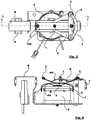
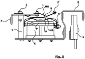
- the preferred embodiment of the electromagnetic brake of the present invention illustrated in the drawings comprises, as standard components entirely similar to those of the traditional brakes, an electromagnet E, a single eyelet thread guide F at the weft thread entry, a two eyelets thread guide B at the weft thread exit and a sensor S sensing the presence of the weft thread placed in between the two eyelets of the exit thread guide B.
- the electromagnet E is provided with an axially movable operating piston P for adjusting the position of a first operated thin plate A of the brake by means of a respective spring element MA, also in laminar form, said spring element MA being interposed between the operating piston P head, to which it is fixed in a central position, and the operated thin plate A, to which it is fixed at its opposite ends.
- the elastic thin plates of the brake are mounted so as to be able to freely oscillate about a central pivoting point.
- said pivoting point is formed into laminar spring elements, MR and MA, which respectively elastically support the resistant thin plate R and the operated thin plate A, to which are in fact stably joined at their opposite ends.
- the MR spring element is joined in 2 and 2' to the resistant thin plate R, while the spring element MA is joined in 3 and 3' to the operated thin plate A.
- the ends of the operated thin plate A and the relative spring element MA are connected to the electromagnet E body by such a constraint as to prevent the thin plate itself to rotate around the operating piston P axis, but also as not to compromise the above described tilting movement of the thin plate itself in a plane containing the weft thread and the thin plate ends.
- the resistant thin plate is hinged at 1, via the respective spring element MR, to a triangular hollow bracket 6 projecting from a vertical supporting fork 7 which is integral with the electromagnetic brake frame.
- the thin plate A is hinged in the axial position, via the respective spring element MA, onto the operating piston P head. Thanks to this arrangement, at any time they are stressed by the action of a weft thread knot entering the brake, the resistant thin plate R and the operated thin plate A can oscillate, in a plane containing the weft thread and the ends of said thin plates, about the respective fulcrums, freely moving and being elastically recalled to the rest position illustrated in the drawings by the action of the spring elements MR, MA.
- the thin plates oscillation inertia is much lower than their translational inertia, so that the shifting of the thin plates of the brake of the present invention under the action of an entering knot is much faster than in traditional brakes. Furthermore, the thin plates oscillation has the effect of increasing the distance between the braking thin plates much more quickly compared to what happens in known brakes only using a translational thin plate shifting; the entry of the knot between the two thin plates is therefore extraordinarily eased also in the case of bulky knots, as it happens for example in jute processing.
- the resistant thin plate R gradually recovers its standard inclination, while the operated thin plate A begins a similar and opposite oscillation to that of thin plate R, oscillation which is also delayed in time and shifted in space due to the offset of the respective fulcrums.
- the operated thin plate A oscillates in the opposite direction thereby so quickly releasing the knot, while the braking action in this phase moves - after a short passage on the knot itself - onto the portions of the thin plates which are upstream of the position of the knot, symmetrically to what was described for the knot entry phase.
- the operated thin plate A oscillates in the opposite direction, in a position where the knot has now no longer contact with the resistant thin plate R.
- the brake geometry thus recovers its initial undisturbed situation.
- the described mechanism could, in a similar way, provide for making the entering knot meet the operated thin plate A first, and the resistant one R afterwards, interchanging the mutual position of the respective fulcrums, moved forward or backward by a set length with respect to the operating piston P axis that determines the central point of contact of the operated thin plate A.
- a weft thread knot is located at one of the thin plates oscillation fulcrums, i.e.
- the opposite thin plate is in contact with the knot in a still fairly distant location from its fulcrum so as to offer sufficient oscillation to allow the passage of the knot without causing the translation of the thin plate and therefore without causing increases of the weft thread tension beyond normal braking values.
- a damping device to be applied to the electromagnetic brake of the present invention is made by a simple strip 5 of elastomeric material, having appropriate elasticity, which connects the free end 2 of the resistant thin plate R with two fixed anchorage points 4 provided at the top of the vertical fork 7, on opposite sides with respect to the free end 2 of the resistant thin plate R. Thanks to this simple device, as soon as the knot has left the resistant thin plate R, the oscillations of this latter are quickly damped by the strip 5, causing its stopping in the standard working position.
- the electromagnetic brake according to the present invention has fully reached the intended objects.
- thanks to the particular structure and arrangement of the resistant thin plate R and the operated thin plate A it is possible to obtain the passage of the weft thread knots through the electromagnetic brake without causing too a high rise of tension on the weft thread and without interrupting the braking effect on the same in any way.
- the new special structure and arrangement of the electromagnetic brake thin plates according to the present invention involve only a very moderate increase in the longitudinal electromagnetic brake bulk, which bulk increase substantially correspond to the existing offset between the resistant thin plate R fulcrum 1 and the operating piston P axis on whose head the operated thin plate A is pivoted.
- the device overall size is thus substantially the same of that of the known type electromagnetic brakes.
- the weft thread comes into contact with the thin plates A and R always in a single point, which changes position as the system geometry varies, whose evolution at the knot passage has been described above, but that always involves only a limited area of the weft thread; there is then no additional abrasive action on the weft thread compared to the traditional type electromagnetic brakes. Also the third object of the present invention is thus fully achieved.
Landscapes
- Engineering & Computer Science (AREA)
- Textile Engineering (AREA)
- Looms (AREA)
- Braking Arrangements (AREA)
Claims (11)
- Gesteuerte elektromagnetische Bremse zur Kontrolle der Spannung der Schussfäden bei Webmaschinen, insbesondere eines Schussfadens, der eine hohe Knotenzahl aufweist, mit einem Paar gegenüberliegender elastischer dünner Platten, zwischen denen der Schussfaden verläuft, einer ersten dünnen Platte, oder betätigten dünnen Platte (A), die durch einen elektromagnetisch gesteuerten Betätigungskolben (P) in ihrer Position justiert wird, und einer zweiten dünnen Platte, oder einer einen Widerstand bildenden Platte (R), einen Widerstand als Antwort auf elastische Kontrastmittel bildend, um die Intensität der Kontrastkraft zwischen dem Paar dünner Platten zu steuern, dadurch gekennzeichnet, dass mindestens eine der genannten einen Widerstand bildenden Platte (R) und der genannten betätigten dünnen Platte (A) einen Drehpunkt in Korrespondenz eines zentralen Abschnitts davon aufweist, um in einer Ebene frei schwingen zu können, die den Schussfaden enthält, während des Durchgangs eines Schussfadenknotens zwischen der genannten einen Widerstand bildenden dünnen Platte (R) und der genannten betätigten dünnen Platte (A).
- Gesteuerte elektromagnetische Bremse nach Anspruch 11, wobei der Drehpunkt von mindestens einer zwischen der genannten einen Widerstand bildenden dünnen Platte (R) und der genannten betätigten dünnen Platte (A) nach hinten oder vorn versetzt ist um eine bestimmte Länge entlang der Laufrichtung des Schussfadens mit Bezug auf den zentralen Kontaktpunkt oder auf den Drehpunkt der anderen zwischen der genannten einen Widerstand bildenden dünnen Platte (R) und der besagten betätigten dünnen Platte (A).
- Gesteuerte elektromagnetische Bremse nach den Ansprüchen 1 oder 2, wobei die einen Widerstand bildende dünne Platte (R) mit einem ersten laminaren Federelement (MR) verbunden und von diesem elastisch abgestützt ist, und ihren eigenen Drehpunkt (1) hat, der in diesem ersten Federelement (MR) gebildet ist.
- Gesteuerte elektromagnetische Bremse nach Anspruch 3, wobei der Drehpunkt (1), der in dem ersten Federelement (MR) ausgebildet ist, auf eine hohle dreieckige Klammer (6) beschränkt ist, die von einer vertikalen Stützgabel (7)vorspringt, die mit dem elektromagnetischen Bremsenrahmen integral ausgebildet ist.
- Gesteuerte elektromagnetische Bremse nach Anspruch 3, wobei die einen Widerstand bildende dünne Platte (R) eine gewölbte Form hat.
- Gesteuerte elektromagnetische Bremse nach Anspruch 3, wobei der Drehpunkt (1) der einen Widerstand bildenden dünnen Platte (R) um eine bestimmte Länge in Bezug auf die Achse des Betätigungskolbens (P) nach hinten oder vorne versetzt ist, die den zentralen Kontaktpunkt der betätigten dünnen Platte (A) bestimmt.
- Gesteuerte elektromagnetische Bremse nach Anspruch 6, wobei die genannte betätigte dünne Platte (A) mit einem zweiten Federelement (MA) verbunden und von diesem elastisch gelagert ist, und ihren eigenen Drehpunkt hat, der in dem zweiten Federelement (MA) gebildet ist.
- Gesteuerte elektromagnetische Bremse nach Anspruch 7, wobei der Drehpunkt, der in dem zweiten Federelement (MA) gebildet ist, an den Kopf des Betätigungskolbens (P) gebunden ist.
- Gesteuerte elektromagnetische Bremse nach Anspruch 8, wobei die Enden der betätigten dünnen Platte (A) und des zweiten Federelements (MA) mit dem Elektromagnetkörper (E) durch eine Verbindung verbunden sind, die geeignet ist, die Drehung der betätigten dünnen Platte (A) um die Achse des Betätigungskolbens (P) zu verhindern, während sie eine oszillierende Bewegung der dünnen Platte selbst in einer Ebene, die den Schussfaden und die Enden (3, 3') der betätigten dünnen Platte (A) enthält, ermöglicht.
- Gesteuerte elektromagnetische Bremse wie in einem der vorhergehenden Ansprüche, weiter umfassend eine Dämpfungsvorrichtung für die Schwingungen mindestens einer der genannten einen Widerstand bildenden dünnen Platte (R) und der besagten betätigten dünnen Platte (A).
- Gesteuerte elektromagnetische Bremse nach Anspruch 10, wobei die Dämpfungsvorrichtung aus einem Streifen (5) aus elastomerem Material besteht, das ein freies Ende (2) der einen Widerstand bildenden dünnen Platte (R) mit zwei Verankerungspunkten (4), die an der Spitze der vertikalen Gabel (7) auf den gegenüberliegenden Seiten des genannten freien Endes (2) der einen Widerstand bildenden dünnen Platte (R) vorgesehen sind, verbindet.
Applications Claiming Priority (2)
| Application Number | Priority Date | Filing Date | Title |
|---|---|---|---|
| ITUB2015A005266A ITUB20155266A1 (it) | 2015-10-30 | 2015-10-30 | Freno elettromagnetico pilotato per il controllo della tensione dei fili di trama in macchine tessili |
| PCT/IB2016/056163 WO2017072622A1 (en) | 2015-10-30 | 2016-10-14 | Piloted electromagnetic brake for controlling the tension of the weft yarn in weaving machines |
Publications (2)
| Publication Number | Publication Date |
|---|---|
| EP3368458A1 EP3368458A1 (de) | 2018-09-05 |
| EP3368458B1 true EP3368458B1 (de) | 2020-05-13 |
Family
ID=55697281
Family Applications (1)
| Application Number | Title | Priority Date | Filing Date |
|---|---|---|---|
| EP16805498.9A Active EP3368458B1 (de) | 2015-10-30 | 2016-10-14 | Vorgesteuerte elektromagnetische bremse zur steuerung der schussfadenspannung in webmaschinen |
Country Status (5)
| Country | Link |
|---|---|
| US (1) | US11434101B2 (de) |
| EP (1) | EP3368458B1 (de) |
| CN (1) | CN108349681B (de) |
| IT (1) | ITUB20155266A1 (de) |
| WO (1) | WO2017072622A1 (de) |
Families Citing this family (1)
| Publication number | Priority date | Publication date | Assignee | Title |
|---|---|---|---|---|
| CN120435597A (zh) | 2022-12-14 | 2025-08-05 | 范德威尔瑞典公司 | 特别是用于重纱线的喂纱器 |
Citations (1)
| Publication number | Priority date | Publication date | Assignee | Title |
|---|---|---|---|---|
| EP2349896A1 (de) * | 2008-10-31 | 2011-08-03 | Picanol | Fadenbremse und verfahren zur verwendung der fadenbremse |
Family Cites Families (15)
| Publication number | Priority date | Publication date | Assignee | Title |
|---|---|---|---|---|
| FR1161662A (fr) * | 1956-11-21 | 1958-09-03 | Perfectionnements aux dispositifs tendeurs de fils | |
| DE4306911C1 (de) * | 1993-03-05 | 1993-12-23 | Dornier Gmbh Lindauer | Schußfadenbremse mit steuerbarer Bremswirkung |
| IT1260645B (it) * | 1993-04-08 | 1996-04-22 | Lgl Electronics Spa | Dispositivo di frenatura modulata del filato per apparecchi alimentatori di trama |
| IT1272696B (it) * | 1993-09-29 | 1997-06-26 | Nuovopignone Ind Meccaniche Ef | Frenafilo di trama perfezionato per telaio tessile senza navetta |
| DE19535895C1 (de) * | 1995-09-27 | 1996-06-13 | Dornier Gmbh Lindauer | Einrichtung zum Reduzieren der Belastung eines in das Webfach einer Webmaschine einzutragenden Schußfadens |
| BE1011089A3 (nl) * | 1997-04-07 | 1999-04-06 | Picanol Nv | Draadrem met twee remelementen. |
| SE9900665D0 (sv) * | 1999-02-23 | 1999-02-23 | Iro Patent Ag | Vorrichtung und Verfahren zum variierenden Bremseneines laufenden Fadens |
| KR100432266B1 (ko) * | 1999-03-22 | 2004-05-22 | 아이알오피에이 악티엔게젤샤프트 | 파워 직조기 내의 씨실 삽입 최적화 및 감시 방법 |
| DE10013625A1 (de) * | 2000-03-18 | 2001-09-27 | Dornier Gmbh Lindauer | Fadenbremse, insbesondere Schussfadenbremse für Webmaschinen |
| DE10107311A1 (de) * | 2001-02-16 | 2002-08-29 | Iro Patent Ag Baar | Fadengreifer |
| DE10151780C1 (de) * | 2001-10-19 | 2003-05-22 | Dornier Gmbh Lindauer | Verfahren und Vorrichtung zur Beeinflussung der Fadenbremskraft einer zwischen einem Garnvorratssystem und einem Fadenspeicher einer Webmaschine angeordneten Schussfadenbremse |
| DE10153326A1 (de) * | 2001-10-29 | 2003-05-08 | Iropa Ag | Fadenverarbeitendes System |
| DE10218059A1 (de) * | 2002-04-23 | 2003-11-13 | Dornier Gmbh Lindauer | Vorrichtung und Verfahren zur Regelung der Fadenspannung eines Fadens bei Textilverarbeitungsmaschinen |
| BE1016183A3 (nl) * | 2004-09-08 | 2006-04-04 | Picanol Nv | Werkwijze en inrichting voor het klemmen van een inslagdraad bij een weefmachine. |
| DE502006003985D1 (de) * | 2006-01-24 | 2009-07-30 | Sultex Ag | Gesteuerte Fadenbremse |
-
2015
- 2015-10-30 IT ITUB2015A005266A patent/ITUB20155266A1/it unknown
-
2016
- 2016-10-14 EP EP16805498.9A patent/EP3368458B1/de active Active
- 2016-10-14 WO PCT/IB2016/056163 patent/WO2017072622A1/en not_active Ceased
- 2016-10-14 CN CN201680063539.9A patent/CN108349681B/zh active Active
- 2016-10-14 US US15/772,016 patent/US11434101B2/en active Active
Patent Citations (1)
| Publication number | Priority date | Publication date | Assignee | Title |
|---|---|---|---|---|
| EP2349896A1 (de) * | 2008-10-31 | 2011-08-03 | Picanol | Fadenbremse und verfahren zur verwendung der fadenbremse |
Also Published As
| Publication number | Publication date |
|---|---|
| WO2017072622A1 (en) | 2017-05-04 |
| CN108349681B (zh) | 2021-04-20 |
| US20180312367A1 (en) | 2018-11-01 |
| EP3368458A1 (de) | 2018-09-05 |
| CN108349681A (zh) | 2018-07-31 |
| US11434101B2 (en) | 2022-09-06 |
| ITUB20155266A1 (it) | 2016-01-30 |
Similar Documents
| Publication | Publication Date | Title |
|---|---|---|
| TWI406985B (zh) | 控制梭子上之緯紗帶張力的裝置,設有該裝置的梭子,和圓形梭織機 | |
| KR100283311B1 (ko) | 직기와 직기를 위한 삽입제동기 | |
| EP3368458B1 (de) | Vorgesteuerte elektromagnetische bremse zur steuerung der schussfadenspannung in webmaschinen | |
| KR101429588B1 (ko) | 마찰 브레이크를 이용한 자가 보상 필라멘트 장력 제어 장치 | |
| JP2010514945A (ja) | 機械織機のバックレスト | |
| RU2592177C2 (ru) | Устройство контроля ленточки основы и круглая ткацкая машина | |
| CN103422232B (zh) | 帘子布织造装置的经纱张力调整装置的经纱施力方法及经纱张力调整装置 | |
| KR20130108458A (ko) | 마찰 밴드 브레이크를 이용한 자가 보상 필라멘트 장력 제어 장치 | |
| EP2652187B1 (de) | Schussfadenzuführung für webstühle | |
| CN101039859B (zh) | 线张紧装置 | |
| EP2829647B1 (de) | Garnzuführvorrichtung mit Schussfaden-Wickeltrommel und feedbackgesteuerter Schussfaden-Bremsvorrichtung | |
| NL8902491A (nl) | Scheringgarenspaninrichting voor een weefgetouw. | |
| US11242626B2 (en) | Narrow fabric needle loom and corresponding weaving method | |
| KR101011389B1 (ko) | 환편기용 메탈릭 플랫 얀 급사장치 | |
| CZ12394A3 (en) | Thread brake | |
| BRPI0405954A (pt) | tear de agulha com mudança automática do fio de trama, e produto têxtil obtido com um tear de agulha | |
| JPH0214451B2 (de) | ||
| KR102701977B1 (ko) | 제직장치 | |
| BE1018327A3 (nl) | Draadrem en werkwijze om de draadrem aan te wenden. | |
| CN102797102A (zh) | 起绒织机的绒头经纱张力调整装置 | |
| US1064280A (en) | Twisting-machine. | |
| US3774415A (en) | Device for winding or unwinding material conducted in web or linear form, particularly groups of textile threads | |
| US2667772A (en) | Auxiliary yarn tensioning means | |
| EP1526102B1 (de) | Bremsvorrichtung für Schussfäden für Textilmaschinen | |
| US3414020A (en) | Warp-tension equalization mechanism for travelling-wave shedding looms |
Legal Events
| Date | Code | Title | Description |
|---|---|---|---|
| STAA | Information on the status of an ep patent application or granted ep patent |
Free format text: STATUS: UNKNOWN |
|
| STAA | Information on the status of an ep patent application or granted ep patent |
Free format text: STATUS: THE INTERNATIONAL PUBLICATION HAS BEEN MADE |
|
| PUAI | Public reference made under article 153(3) epc to a published international application that has entered the european phase |
Free format text: ORIGINAL CODE: 0009012 |
|
| STAA | Information on the status of an ep patent application or granted ep patent |
Free format text: STATUS: REQUEST FOR EXAMINATION WAS MADE |
|
| 17P | Request for examination filed |
Effective date: 20180426 |
|
| AK | Designated contracting states |
Kind code of ref document: A1 Designated state(s): AL AT BE BG CH CY CZ DE DK EE ES FI FR GB GR HR HU IE IS IT LI LT LU LV MC MK MT NL NO PL PT RO RS SE SI SK SM TR |
|
| AX | Request for extension of the european patent |
Extension state: BA ME |
|
| DAV | Request for validation of the european patent (deleted) | ||
| DAX | Request for extension of the european patent (deleted) | ||
| GRAP | Despatch of communication of intention to grant a patent |
Free format text: ORIGINAL CODE: EPIDOSNIGR1 |
|
| STAA | Information on the status of an ep patent application or granted ep patent |
Free format text: STATUS: GRANT OF PATENT IS INTENDED |
|
| INTG | Intention to grant announced |
Effective date: 20200114 |
|
| GRAS | Grant fee paid |
Free format text: ORIGINAL CODE: EPIDOSNIGR3 |
|
| GRAL | Information related to payment of fee for publishing/printing deleted |
Free format text: ORIGINAL CODE: EPIDOSDIGR3 |
|
| GRAS | Grant fee paid |
Free format text: ORIGINAL CODE: EPIDOSNIGR3 |
|
| GRAA | (expected) grant |
Free format text: ORIGINAL CODE: 0009210 |
|
| STAA | Information on the status of an ep patent application or granted ep patent |
Free format text: STATUS: THE PATENT HAS BEEN GRANTED |
|
| AK | Designated contracting states |
Kind code of ref document: B1 Designated state(s): AL AT BE BG CH CY CZ DE DK EE ES FI FR GB GR HR HU IE IS IT LI LT LU LV MC MK MT NL NO PL PT RO RS SE SI SK SM TR |
|
| REG | Reference to a national code |
Ref country code: GB Ref legal event code: FG4D |
|
| REG | Reference to a national code |
Ref country code: CH Ref legal event code: EP |
|
| REG | Reference to a national code |
Ref country code: DE Ref legal event code: R096 Ref document number: 602016036479 Country of ref document: DE |
|
| REG | Reference to a national code |
Ref country code: AT Ref legal event code: REF Ref document number: 1270006 Country of ref document: AT Kind code of ref document: T Effective date: 20200615 |
|
| REG | Reference to a national code |
Ref country code: LT Ref legal event code: MG4D |
|
| REG | Reference to a national code |
Ref country code: NL Ref legal event code: MP Effective date: 20200513 |
|
| PG25 | Lapsed in a contracting state [announced via postgrant information from national office to epo] |
Ref country code: LT Free format text: LAPSE BECAUSE OF FAILURE TO SUBMIT A TRANSLATION OF THE DESCRIPTION OR TO PAY THE FEE WITHIN THE PRESCRIBED TIME-LIMIT Effective date: 20200513 Ref country code: NO Free format text: LAPSE BECAUSE OF FAILURE TO SUBMIT A TRANSLATION OF THE DESCRIPTION OR TO PAY THE FEE WITHIN THE PRESCRIBED TIME-LIMIT Effective date: 20200813 Ref country code: GR Free format text: LAPSE BECAUSE OF FAILURE TO SUBMIT A TRANSLATION OF THE DESCRIPTION OR TO PAY THE FEE WITHIN THE PRESCRIBED TIME-LIMIT Effective date: 20200814 Ref country code: FI Free format text: LAPSE BECAUSE OF FAILURE TO SUBMIT A TRANSLATION OF THE DESCRIPTION OR TO PAY THE FEE WITHIN THE PRESCRIBED TIME-LIMIT Effective date: 20200513 Ref country code: SE Free format text: LAPSE BECAUSE OF FAILURE TO SUBMIT A TRANSLATION OF THE DESCRIPTION OR TO PAY THE FEE WITHIN THE PRESCRIBED TIME-LIMIT Effective date: 20200513 Ref country code: PT Free format text: LAPSE BECAUSE OF FAILURE TO SUBMIT A TRANSLATION OF THE DESCRIPTION OR TO PAY THE FEE WITHIN THE PRESCRIBED TIME-LIMIT Effective date: 20200914 Ref country code: IS Free format text: LAPSE BECAUSE OF FAILURE TO SUBMIT A TRANSLATION OF THE DESCRIPTION OR TO PAY THE FEE WITHIN THE PRESCRIBED TIME-LIMIT Effective date: 20200913 |
|
| PG25 | Lapsed in a contracting state [announced via postgrant information from national office to epo] |
Ref country code: LV Free format text: LAPSE BECAUSE OF FAILURE TO SUBMIT A TRANSLATION OF THE DESCRIPTION OR TO PAY THE FEE WITHIN THE PRESCRIBED TIME-LIMIT Effective date: 20200513 Ref country code: RS Free format text: LAPSE BECAUSE OF FAILURE TO SUBMIT A TRANSLATION OF THE DESCRIPTION OR TO PAY THE FEE WITHIN THE PRESCRIBED TIME-LIMIT Effective date: 20200513 Ref country code: HR Free format text: LAPSE BECAUSE OF FAILURE TO SUBMIT A TRANSLATION OF THE DESCRIPTION OR TO PAY THE FEE WITHIN THE PRESCRIBED TIME-LIMIT Effective date: 20200513 Ref country code: BG Free format text: LAPSE BECAUSE OF FAILURE TO SUBMIT A TRANSLATION OF THE DESCRIPTION OR TO PAY THE FEE WITHIN THE PRESCRIBED TIME-LIMIT Effective date: 20200813 |
|
| REG | Reference to a national code |
Ref country code: AT Ref legal event code: MK05 Ref document number: 1270006 Country of ref document: AT Kind code of ref document: T Effective date: 20200513 |
|
| PG25 | Lapsed in a contracting state [announced via postgrant information from national office to epo] |
Ref country code: NL Free format text: LAPSE BECAUSE OF FAILURE TO SUBMIT A TRANSLATION OF THE DESCRIPTION OR TO PAY THE FEE WITHIN THE PRESCRIBED TIME-LIMIT Effective date: 20200513 Ref country code: AL Free format text: LAPSE BECAUSE OF FAILURE TO SUBMIT A TRANSLATION OF THE DESCRIPTION OR TO PAY THE FEE WITHIN THE PRESCRIBED TIME-LIMIT Effective date: 20200513 |
|
| PG25 | Lapsed in a contracting state [announced via postgrant information from national office to epo] |
Ref country code: CZ Free format text: LAPSE BECAUSE OF FAILURE TO SUBMIT A TRANSLATION OF THE DESCRIPTION OR TO PAY THE FEE WITHIN THE PRESCRIBED TIME-LIMIT Effective date: 20200513 Ref country code: EE Free format text: LAPSE BECAUSE OF FAILURE TO SUBMIT A TRANSLATION OF THE DESCRIPTION OR TO PAY THE FEE WITHIN THE PRESCRIBED TIME-LIMIT Effective date: 20200513 Ref country code: AT Free format text: LAPSE BECAUSE OF FAILURE TO SUBMIT A TRANSLATION OF THE DESCRIPTION OR TO PAY THE FEE WITHIN THE PRESCRIBED TIME-LIMIT Effective date: 20200513 Ref country code: SM Free format text: LAPSE BECAUSE OF FAILURE TO SUBMIT A TRANSLATION OF THE DESCRIPTION OR TO PAY THE FEE WITHIN THE PRESCRIBED TIME-LIMIT Effective date: 20200513 Ref country code: DK Free format text: LAPSE BECAUSE OF FAILURE TO SUBMIT A TRANSLATION OF THE DESCRIPTION OR TO PAY THE FEE WITHIN THE PRESCRIBED TIME-LIMIT Effective date: 20200513 Ref country code: ES Free format text: LAPSE BECAUSE OF FAILURE TO SUBMIT A TRANSLATION OF THE DESCRIPTION OR TO PAY THE FEE WITHIN THE PRESCRIBED TIME-LIMIT Effective date: 20200513 Ref country code: RO Free format text: LAPSE BECAUSE OF FAILURE TO SUBMIT A TRANSLATION OF THE DESCRIPTION OR TO PAY THE FEE WITHIN THE PRESCRIBED TIME-LIMIT Effective date: 20200513 |
|
| REG | Reference to a national code |
Ref country code: DE Ref legal event code: R097 Ref document number: 602016036479 Country of ref document: DE |
|
| PG25 | Lapsed in a contracting state [announced via postgrant information from national office to epo] |
Ref country code: SK Free format text: LAPSE BECAUSE OF FAILURE TO SUBMIT A TRANSLATION OF THE DESCRIPTION OR TO PAY THE FEE WITHIN THE PRESCRIBED TIME-LIMIT Effective date: 20200513 Ref country code: PL Free format text: LAPSE BECAUSE OF FAILURE TO SUBMIT A TRANSLATION OF THE DESCRIPTION OR TO PAY THE FEE WITHIN THE PRESCRIBED TIME-LIMIT Effective date: 20200513 |
|
| PLBE | No opposition filed within time limit |
Free format text: ORIGINAL CODE: 0009261 |
|
| STAA | Information on the status of an ep patent application or granted ep patent |
Free format text: STATUS: NO OPPOSITION FILED WITHIN TIME LIMIT |
|
| 26N | No opposition filed |
Effective date: 20210216 |
|
| PG25 | Lapsed in a contracting state [announced via postgrant information from national office to epo] |
Ref country code: SI Free format text: LAPSE BECAUSE OF FAILURE TO SUBMIT A TRANSLATION OF THE DESCRIPTION OR TO PAY THE FEE WITHIN THE PRESCRIBED TIME-LIMIT Effective date: 20200513 |
|
| REG | Reference to a national code |
Ref country code: CH Ref legal event code: PL |
|
| GBPC | Gb: european patent ceased through non-payment of renewal fee |
Effective date: 20201014 |
|
| PG25 | Lapsed in a contracting state [announced via postgrant information from national office to epo] |
Ref country code: MC Free format text: LAPSE BECAUSE OF FAILURE TO SUBMIT A TRANSLATION OF THE DESCRIPTION OR TO PAY THE FEE WITHIN THE PRESCRIBED TIME-LIMIT Effective date: 20200513 Ref country code: LU Free format text: LAPSE BECAUSE OF NON-PAYMENT OF DUE FEES Effective date: 20201014 |
|
| PG25 | Lapsed in a contracting state [announced via postgrant information from national office to epo] |
Ref country code: FR Free format text: LAPSE BECAUSE OF NON-PAYMENT OF DUE FEES Effective date: 20201031 |
|
| PG25 | Lapsed in a contracting state [announced via postgrant information from national office to epo] |
Ref country code: CH Free format text: LAPSE BECAUSE OF NON-PAYMENT OF DUE FEES Effective date: 20201031 Ref country code: LI Free format text: LAPSE BECAUSE OF NON-PAYMENT OF DUE FEES Effective date: 20201031 Ref country code: GB Free format text: LAPSE BECAUSE OF NON-PAYMENT OF DUE FEES Effective date: 20201014 |
|
| PG25 | Lapsed in a contracting state [announced via postgrant information from national office to epo] |
Ref country code: IE Free format text: LAPSE BECAUSE OF NON-PAYMENT OF DUE FEES Effective date: 20201014 |
|
| PG25 | Lapsed in a contracting state [announced via postgrant information from national office to epo] |
Ref country code: MT Free format text: LAPSE BECAUSE OF FAILURE TO SUBMIT A TRANSLATION OF THE DESCRIPTION OR TO PAY THE FEE WITHIN THE PRESCRIBED TIME-LIMIT Effective date: 20200513 Ref country code: CY Free format text: LAPSE BECAUSE OF FAILURE TO SUBMIT A TRANSLATION OF THE DESCRIPTION OR TO PAY THE FEE WITHIN THE PRESCRIBED TIME-LIMIT Effective date: 20200513 |
|
| PG25 | Lapsed in a contracting state [announced via postgrant information from national office to epo] |
Ref country code: MK Free format text: LAPSE BECAUSE OF FAILURE TO SUBMIT A TRANSLATION OF THE DESCRIPTION OR TO PAY THE FEE WITHIN THE PRESCRIBED TIME-LIMIT Effective date: 20200513 |
|
| P01 | Opt-out of the competence of the unified patent court (upc) registered |
Effective date: 20230519 |
|
| PGFP | Annual fee paid to national office [announced via postgrant information from national office to epo] |
Ref country code: TR Payment date: 20250929 Year of fee payment: 10 Ref country code: IT Payment date: 20250926 Year of fee payment: 10 |
|
| PGFP | Annual fee paid to national office [announced via postgrant information from national office to epo] |
Ref country code: DE Payment date: 20250926 Year of fee payment: 10 |
|
| PGFP | Annual fee paid to national office [announced via postgrant information from national office to epo] |
Ref country code: BE Payment date: 20251030 Year of fee payment: 10 |