EP3368486B1 - Procédé pour électrodésinfection - Google Patents
Procédé pour électrodésinfection Download PDFInfo
- Publication number
- EP3368486B1 EP3368486B1 EP16858551.1A EP16858551A EP3368486B1 EP 3368486 B1 EP3368486 B1 EP 3368486B1 EP 16858551 A EP16858551 A EP 16858551A EP 3368486 B1 EP3368486 B1 EP 3368486B1
- Authority
- EP
- European Patent Office
- Prior art keywords
- reactor
- water
- electrolytic
- cooling tower
- cathode
- Prior art date
- Legal status (The legal status is an assumption and is not a legal conclusion. Google has not performed a legal analysis and makes no representation as to the accuracy of the status listed.)
- Active
Links
- RKTPCTKFTDSWND-UHFFFAOYSA-N CCCC1SCCC1 Chemical compound CCCC1SCCC1 RKTPCTKFTDSWND-UHFFFAOYSA-N 0.000 description 1
Images



Classifications
-
- C—CHEMISTRY; METALLURGY
- C02—TREATMENT OF WATER, WASTE WATER, SEWAGE, OR SLUDGE
- C02F—TREATMENT OF WATER, WASTE WATER, SEWAGE, OR SLUDGE
- C02F1/00—Treatment of water, waste water, or sewage
- C02F1/46—Treatment of water, waste water, or sewage by electrochemical methods
- C02F1/461—Treatment of water, waste water, or sewage by electrochemical methods by electrolysis
- C02F1/467—Treatment of water, waste water, or sewage by electrochemical methods by electrolysis by electrochemical disinfection; by electrooxydation or by electroreduction
-
- C—CHEMISTRY; METALLURGY
- C02—TREATMENT OF WATER, WASTE WATER, SEWAGE, OR SLUDGE
- C02F—TREATMENT OF WATER, WASTE WATER, SEWAGE, OR SLUDGE
- C02F1/00—Treatment of water, waste water, or sewage
- C02F1/46—Treatment of water, waste water, or sewage by electrochemical methods
- C02F1/461—Treatment of water, waste water, or sewage by electrochemical methods by electrolysis
- C02F1/46104—Devices therefor; Their operating or servicing
- C02F1/46109—Electrodes
-
- C—CHEMISTRY; METALLURGY
- C02—TREATMENT OF WATER, WASTE WATER, SEWAGE, OR SLUDGE
- C02F—TREATMENT OF WATER, WASTE WATER, SEWAGE, OR SLUDGE
- C02F1/00—Treatment of water, waste water, or sewage
- C02F1/46—Treatment of water, waste water, or sewage by electrochemical methods
- C02F1/461—Treatment of water, waste water, or sewage by electrochemical methods by electrolysis
- C02F1/46104—Devices therefor; Their operating or servicing
- C02F1/46109—Electrodes
- C02F2001/46133—Electrodes characterised by the material
- C02F2001/46138—Electrodes comprising a substrate and a coating
- C02F2001/46142—Catalytic coating
-
- C—CHEMISTRY; METALLURGY
- C02—TREATMENT OF WATER, WASTE WATER, SEWAGE, OR SLUDGE
- C02F—TREATMENT OF WATER, WASTE WATER, SEWAGE, OR SLUDGE
- C02F1/00—Treatment of water, waste water, or sewage
- C02F1/46—Treatment of water, waste water, or sewage by electrochemical methods
- C02F1/461—Treatment of water, waste water, or sewage by electrochemical methods by electrolysis
- C02F1/46104—Devices therefor; Their operating or servicing
- C02F1/46109—Electrodes
- C02F2001/46133—Electrodes characterised by the material
- C02F2001/46138—Electrodes comprising a substrate and a coating
- C02F2001/46147—Diamond coating
-
- C—CHEMISTRY; METALLURGY
- C02—TREATMENT OF WATER, WASTE WATER, SEWAGE, OR SLUDGE
- C02F—TREATMENT OF WATER, WASTE WATER, SEWAGE, OR SLUDGE
- C02F1/00—Treatment of water, waste water, or sewage
- C02F1/46—Treatment of water, waste water, or sewage by electrochemical methods
- C02F1/461—Treatment of water, waste water, or sewage by electrochemical methods by electrolysis
- C02F1/46104—Devices therefor; Their operating or servicing
- C02F1/46109—Electrodes
- C02F2001/46152—Electrodes characterised by the shape or form
- C02F2001/46171—Cylindrical or tubular shaped
-
- C—CHEMISTRY; METALLURGY
- C02—TREATMENT OF WATER, WASTE WATER, SEWAGE, OR SLUDGE
- C02F—TREATMENT OF WATER, WASTE WATER, SEWAGE, OR SLUDGE
- C02F2103/00—Nature of the water, waste water, sewage or sludge to be treated
- C02F2103/008—Originating from marine vessels, ships and boats, e.g. bilge water or ballast water
-
- C—CHEMISTRY; METALLURGY
- C02—TREATMENT OF WATER, WASTE WATER, SEWAGE, OR SLUDGE
- C02F—TREATMENT OF WATER, WASTE WATER, SEWAGE, OR SLUDGE
- C02F2103/00—Nature of the water, waste water, sewage or sludge to be treated
- C02F2103/02—Non-contaminated water, e.g. for industrial water supply
- C02F2103/023—Water in cooling circuits
-
- C—CHEMISTRY; METALLURGY
- C02—TREATMENT OF WATER, WASTE WATER, SEWAGE, OR SLUDGE
- C02F—TREATMENT OF WATER, WASTE WATER, SEWAGE, OR SLUDGE
- C02F2201/00—Apparatus for treatment of water, waste water or sewage
- C02F2201/46—Apparatus for electrochemical processes
- C02F2201/461—Electrolysis apparatus
- C02F2201/46105—Details relating to the electrolytic devices
- C02F2201/4611—Fluid flow
-
- C—CHEMISTRY; METALLURGY
- C02—TREATMENT OF WATER, WASTE WATER, SEWAGE, OR SLUDGE
- C02F—TREATMENT OF WATER, WASTE WATER, SEWAGE, OR SLUDGE
- C02F2301/00—General aspects of water treatment
- C02F2301/02—Fluid flow conditions
- C02F2301/024—Turbulent
-
- C—CHEMISTRY; METALLURGY
- C02—TREATMENT OF WATER, WASTE WATER, SEWAGE, OR SLUDGE
- C02F—TREATMENT OF WATER, WASTE WATER, SEWAGE, OR SLUDGE
- C02F2303/00—Specific treatment goals
- C02F2303/04—Disinfection
-
- Y—GENERAL TAGGING OF NEW TECHNOLOGICAL DEVELOPMENTS; GENERAL TAGGING OF CROSS-SECTIONAL TECHNOLOGIES SPANNING OVER SEVERAL SECTIONS OF THE IPC; TECHNICAL SUBJECTS COVERED BY FORMER USPC CROSS-REFERENCE ART COLLECTIONS [XRACs] AND DIGESTS
- Y02—TECHNOLOGIES OR APPLICATIONS FOR MITIGATION OR ADAPTATION AGAINST CLIMATE CHANGE
- Y02W—CLIMATE CHANGE MITIGATION TECHNOLOGIES RELATED TO WASTEWATER TREATMENT OR WASTE MANAGEMENT
- Y02W10/00—Technologies for wastewater treatment
- Y02W10/30—Wastewater or sewage treatment systems using renewable energies
- Y02W10/37—Wastewater or sewage treatment systems using renewable energies using solar energy
Definitions
- the present invention generally relates to a method for electrodisinfection for removing microorganisms from water.
- Disinfection methods can be divided into two main groups, namely physical and chemical processing methods (Metcalf and Eddy, 2003).
- Physical methods include: electromagnetic radiation, ultrasonic waves, heat, visible light and ultraviolet (UV) radiation, ionizing radiation (gamma and X), electron beam and electric current.
- Chemical methods use different compounds: especially halogens (Cl 2 , Br 2 , I 2 , HOCl, OCl, ClO 2 , HOBr, HOI, etc.), oxygenated and highly oxidizing compounds (ozone, hydrogen peroxide, phenols, alcohols, percarbonate and persulfate, peracetic acid, potassium permanganate, etc.), quaternary ammonium compounds, acids and bases, and enzymes.
- halogens Cl 2 , Br 2 , I 2 , HOCl, OCl, ClO 2 , HOBr, HOI, etc.
- oxygenated and highly oxidizing compounds ozone, hydrogen peroxide, phenols, alcohols, percarbonate and persulfate, peracetic acid, potassium permanganate, etc.
- quaternary ammonium compounds acids and bases, and enzymes.
- micro-organisms inactivating mechanisms comprise one or a combination of the following phenomena (Prescott, 1995):
- Disinfection is primarily determined by the ability of the bactericidal agent to oxidize and break the membrane and by its ability to diffuse into the cell. For example, chlorine diffuses into the cell and generates a malfunction of internal enzymes, inactivating the cell (Diao et al. 2004). Chlorine may also react with the constituents of the cell membrane. Otherwise, ozone is attributed to its high oxidation potential which directly causes degradation of the cell membrane and causes osmotic lysis. Produced hydroxyl radicals via the Fenton reaction will also degrade the cell membrane.
- Tolentino-Bisneto and Bidoia (2003) examined the effect of low current (0.6 A and 8 to 11 V) on Bacillus subtilis in water and suggest that the reduction also comes from the electroporation. According to Matsunaga et al. (1992), inactivation is produced by the electrochemical oxidation of coenzyme A. Drees et al. (2003) explain this phenomena by the oxidative stress generated by an irreversible permeabilization of cell membrane caused by the electric field inducing the electrochemical oxidation of critical cellular components.
- the pollutants are oxidized after adsorption on the anode surface without the involvement of any substances other than the electron, which is a "clean reagent".
- high electrochemical rates have been observed using noble metals such as Pt and Pd, and metal-oxide anodes such as iridium dioxide, ruthenium-titanium dioxide, and iridium-titanium dioxide (Foti et al. 1997).
- Microorganisms belong to five categories: bacteria, viruses, protozoa, fungi and helminths. Only some of them are said pathogens because they have the potential to cause illness.
- the quantities of pathogenic microorganisms vary depending on various parameters including: the nature of the collected waste (municipal, industrial %), the amount of discharge treated, the health of the release and the type of treatment performed.
- Microorganisms are present in all environments and are mostly able to withstand very adverse environmental conditions.
- the bacteria must resist the osmotic pressure caused by the fact that their cytoplasm is strongly hypertonic relative to the external environment.
- the structure of the membrane cell is capable of withstanding osmotic pressures up to 20 bar (Prescott et al. 1995 cited supra).
- bacteria Bacillus, Clostridium and Sporosarcina expressed sporulating. They have the property of generating a protective cap that protects against dehydration and high temperatures. Viruses are protected from adverse conditions in their capsid or envelope. Depending of the different characteristics of microorganisms, the technology used for disinfection is variable.
- Legionella pneumophila infection can cause a severe form of pneumonia, called Legionnaires' disease (Cunha, 2010). This bacterium is present worldwide. So infections are reported in all continents (Edelstein, 1988). The most common agent of Legionnaires' disease is Legionella pneumophila serogroup 1, which is the source of 61 to 88% of reported cases (Tijet et al., 2010).
- a water cooling tower operates as a heat exchanger by direct contact between the water and the ambient air. Its effectiveness depends on the contact surface between the liquid element and air. To maximize the contact surface, the water is distributed as droplets in a stream of air passing through the tower thus the heat is dissipated into the ambient air and that the water is cooled. An amount of the water volume flowing through the apparatus is driven out by the fans. When this water is contaminated, the neighborhood is exposed to potentially infectious bacteria. So, three thresholds are introduced: ⁇ 1000 CFU/L; between 1000 and 100 000 CFU/L and> 100 000 CFU/L of Legionella pneumophila serogroup 1 and Legionella pneumophila serogroup 2-15. These three thresholds determine the quality of the circulating water in the tower. The last two thresholds require curative actions.
- the water should be filtered to remove particulates, and also be dosed with biocides and algaecides to prevent growths that could interfere with the continuous flow of the water.
- the present invention has the ability to eliminate bacteria and microalgae simultaneously.
- the invention is first directed to a method for the electro-disinfection of water extracted from a cooling tower containing bacteria.
- the method comprises the steps of:
- the anodes are DSAs comprising a titanium metallic base covered by a conducting layer of iridium dioxide.
- the vertical electrolytic reactor defines an electrolysation chamber extending from the top of the reactor and containing the anode(s) and cathode(s) substantially parallel to a flow of the water created from the bottom to the top of the reactor when the water is injected into the reactor; and a flow dispersion chamber located below the electrocoagulation chamber and in fluid communication with the inlet.
- the rods are operatively connected to one or two top crown member to form an electrode cartridge.
- the crown members are configured to be operatively connected to the power supply.
- the top crown member is also configured to seal the top section of the vertical tubular reactor once the electrode cartridge is inserted into the reactor, the electrode cartridge being removable from the reactor for the maintenance of the anodes and cathode.
- the power supply provides a current with an amperage between 10A and 80A, corresponding to 6V and 40V respectively, in order to reduce a treatment time of the water.
- the electrolytic apparatus assembly comprises a number N of electrolytic vertical units with N ⁇ 2, and disposed in a parallel configuration to form a modular unit of N reactors, the outlet of the (N-1) th electrolytic unit being fluidly connected to the inlet of the N th electrolytic unit, the number N being selected in accordance with a volume of water to be treated.
- the number N can be 2, 3 or 4, and even more than 4 if need be.
- the water to electro-disinfect is water circulating in a cooling tower and containing bacteria, such as Legionella and/or E. coli.
- bacteria such as Legionella and/or E. coli.
- the present invention has the ability to eliminate bacteria and microalgae simultaneously.
- the use of biocides and additional filter is eliminated in cooling towers to prevent the growth of Legionella, including species that cause Legionnaires' disease, is eliminated.
- the present invention uses amperages between 10A and 80A, corresponding to 6V and 40V respectively, in order to reduce treatment time.
- the electrolytic treatment breaks the cell membrane of bacteria present in the water.
- the treatment is particularly adapted for eliminating bacteria such as Legionella and/or E. coli.
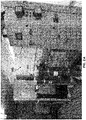
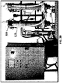
- a system 100 comprising a plurality of electrodisinfection reactors 110-116 is shown.
- the reactors are arranged in a modular arrangement or configuration to make up an electrolysis unit 120.
- four electrolysis reactors are arranged in a single unit 120.
- two electrolysis reactors are arranged in a single unit 120. It has to be understood that the number of reactors required for treatment of fluid, will be a function of the dosage that must be applied to the concentration of microorganisms to be destroyed. Moreover, the design may be optimized with respect to other process steps and with respect to the working conditions that are being used.
- a unit could potentially comprise 1, 2, 3, 4, 5, or even more reactors.
- the actual configuration of the reactors in each unit may also vary and is typically left to the discretion of the client, depending on specifications and constraints such as the available footprint.
- Each reactor of the unit 120 are electrically powered with a power supply system 130 providing a continuous current 134.
- the power supply system may be controlled by a control panel 130, including a Programmable Logic Controller (PLC) and a Human Machine Interface (HMI).
- PLC Programmable Logic Controller
- HMI Human Machine Interface
- the first reactor 110 is fed with the influent 122 to be treated via an inlet 124 located at the bottom of the reactor.
- the influent exits the reactor via an outlet 126 located at the top of the reactor 110 before entering via the inlet 124 of the second reactor 112.
- the reactors 110 - 112 are connected with flexible tubes 125.
- the same influent connections repeat with the third and fourth reactors (114, 116) before exiting the fourth reactor 116 via the outlet 126.
- a valve 128 at the exit of the unit120 can be turned off if necessary.
- Each reactor has a valve 118 connected to the inlet 124 to purge the reactor when needed.
- the system may also comprise two high temperature switches 140, one at the top and one at the bottom of the reactor, generally used to prevent overheating of the electrolysis reactors 110 in no-flow or in low-flow conditions.
- the high temperature switches are generally connected to a security relay installed in the control panel 130. In the event that one of the high temperature switches is activated due to a rise in temperature in the reactor beyond a pre-defined temperature setting, the security relay shall turn off the system and the corresponding DC power supply in order to prevent the overheating of the reactor.
- the reactor is fed from an inlet 124 preferably located at the bottom of the reactor.
- the effluent may exist the reactor 110 via an outlet 126 preferably located at the top of the reactor.
- the reactor may adapted to provide turbulent or transition type of flow rate in order to insure a continuous cleaning of the anode(s) and cathode(s) (see also US2015/0251932 A1 cited above for more details).
- the reactor 110 further comprises quick-tightening bolts 170 to secure the loading top of the reactor.
- an electrolysis reactor 110 according to another preferred embodiment is shown.
- a flow dispersion chamber 115 that helps distributing the rising flow in an evenly fashion throughout the cross-sectional area 117 between the anode(s) 119 and the cathode(s) 121-123.
- the external cathode 123 can extend from the external wall of the reactor 125 or being the wall itself.
- Such a configuration is desired to make sure the fluid is forced through the reactive areas.
- the only way for the fluid to make its way out of the reactor is by passing through the reactive zone of the reactor, also named electrolytic chamber 127, thereby being subjected to the electrolysis reaction. In such a configuration, no bypass is possible. Consequently, this configuration ensures that all the fluid is exposed to the electrolysis treatment.
- a cartridge 600 of six DAS or BOD anode rods 610 is illustrated.
- the rods 610 are generally inserted between an inner cathode 620 and an outer cathode 125 extending from the vertical tubular housing of the reactor (see Figure 5 ).
- the DAS or BDD rods 610 extends from a top and bottom crown members 640-650.
- the crown members and rods form the cartridge 600.
- a nonconductive material 660 can be inserted between the rods for the sake of security.
- FIG. 7 it is shown quick-loading electrode replacement cartridges that can be typically inserted into the body of the reactor having nine (9) rods (A, B and C) or fifteen (15) rods (D), and in each case a central cathode 720.
- Anodes and cathode extend from the crown members 740 or750.
- Figure 7 (C) shows a crown member 740 having 9 rods extending therefrom separated by an isolating member 741
- Figure 6 (D) shows a crown member 750 having 15 rods extending therefrom separated by an isolating member 751.
- electrical connections for the DC power supply to the electrical distribution rings are generally made at the top or the reactor, through a pair of circular holes that are drilled into the water-tight crown (see US 2015/0251932A1 for details).
- Various instruments may be installed in the system in order to monitor or control process parameters, such as pH, temperature, conductivity, and turbidity.
- the design of the reactor may perform efficiently for treating solutions characterized by a relatively wide range of conductivity values.
- Design optimization of the reactor such as the use of more than one cathode, the use of a larger useful anode area, or the use of a tighter inter-electrodes gap can gear the reactor for treatment in a lower conductivity fluid.
- the method according to the present invention is therefore flexible enough to be suited for disinfection in fresh water, brackish water, salt water environment or any kind of water susceptible to transport bacteria, germs, microalgae or any kind of potentially lethal microorganisms.
- the apparatus comprises anodes which are commonly named Dimensionnally Stable Anode (or DSA).
- DSA are generally made of a metal support (here titanium) on which a conducting coating of iridium dioxide is applied. Titanium is generally selected for its excellent corrosion resistance related to chlorides allowing water disinfection treatment without any material risk of contamination or any substantial loss in overall product quality.
- the method of electrolysis according to the present invention could be performed in a single pass or through multiple passes through the unit of reactors.
- a unit of automated ON/OFF valves may be used to direct the fluid in a loop so that it effectively passes multiple times through the unit of reactors until the treatment is completed.
- the flow rate in the treatment loop and through the reactors may be controlled to optimize the treatment, and to maintain the optimal flow rate when performing electrolysis in the reactor.
- the flow rate in the treatment loop may also be adjusted by sizing the feed pump accordingly and through the use of an automatically controlled and modulating valve and the inlet of the feed line. Once the electrolysis treatment is completed, this modulating valve, as well as the other ON/OFF valves can be controlled to stop the treatment.
- the method generally uses a flow control module in order to ensure that a transition or turbulent flow regime is maintained in the reactor throughout the treatment process.
- the type of flow regime will impact the collision rate in the fluid.
- the turbulent flow regime will generally promote the collision rate between different particles thereby increasing the kinetic energy of the fluid during electrolysis, while allowing cleaning up the surface of the anode(s) and cathode(s) on a continuous basis.
- the apparatus for disinfection may also comprise a feed tank equipped with level sensors and control instruments, a flow meter and an automated and modulating valve on the feed line, a modular unit of electrolysis reactors fed from the bottom and each loaded with a quick replacement electrodes cartridge, if needed.
- Table 1 shows the results of domestic water treatment with ECOTHORTM, with DSA anodes. While Table 2 shows the results with ANO2M anodes.
- Table 3 is obtained after water treatment in a cooling tower with ECOTHOR, with DSA anodes.
- Table 4 is the continuity of Table 3 showing additional results obtained after 30 September 2015 using a pilot installed in a hospital.
- Table 1 results of domestic water treatment with ECOTHORTM, with DSA anodes: DSA E. Coli Raw (UFC/100ml) Treated (UFC/100ml) 15 sept 15 20000 ⁇ 10 7 oct 15 >60000 27
- Table 2 the results with ANO2M anodes ANO2M E.
Landscapes
- Chemical & Material Sciences (AREA)
- Chemical Kinetics & Catalysis (AREA)
- Electrochemistry (AREA)
- General Chemical & Material Sciences (AREA)
- Life Sciences & Earth Sciences (AREA)
- Hydrology & Water Resources (AREA)
- Engineering & Computer Science (AREA)
- Environmental & Geological Engineering (AREA)
- Water Supply & Treatment (AREA)
- Organic Chemistry (AREA)
- Water Treatment By Electricity Or Magnetism (AREA)
Claims (8)
- Procédé d'électro-désinfection de l'eau extraite d'une tour de refroidissement contenant des bactéries, le procédé étant caractérisé en ce qu'il comprend les étapes consistant à :• injecter l'eau extraite de la tour de refroidissement à l'intérieur d'un ensemble d'appareil électrolytique (100) comprenant :au moins une unité électrolytique verticale (110), chaque unité comprenant :
 - un réacteur tubulaire vertical (120) qui présente une section inférieure et une section supérieure, une entrée (124) étant située à proximité de la section inférieure du réacteur dans le but d'injecter l'eau (122) à traiter à l'intérieur du réacteur (120),- une sortie (126) située à proximité de la section supérieure du réacteur dans le but d'extraire l'eau du réacteur (120), la sortie (124) du réacteur (120) étant reliée de façon fluidique à la tour de refroidissement de manière à réinjecter l'eau à l'intérieur de la tour de refroidissement après le traitement, et- au moins une anode (119) et au moins une cathode (121, 123) qui sont situées à l'intérieur du réacteur et qui sont configurées de manière à être connectées de façon opérationnelle à une alimentation électrique (130) qui fournit du courant continu (134) à la (aux) anode(s) et à la (aux) cathode(s) dans le but d'électrolyser l'eau qui s'écoule à l'intérieur du réacteur (120) afin de tuer au moins partiellement les bactéries présentes dans l'eau ; etune unité de pompe qui est connectée de façon opérationnelle à l'entrée (124) et à la tour de refroidissement dans le but d'extraire de la tour de refroidissement l'eau à traiter qui a préalablement circulé à l'intérieur de la tour de refroidissement et d'injecter l'eau à traiter à l'intérieur du réacteur (120),
dans lequel :chaque anode est une anode dimensionnellement stable, également appelée DSA ; le réacteur tubulaire vertical (120) est configuré de manière à former une seconde cathode tubulaire (123), ou une seconde cathode (123) s'étend à partir d'une paroi interne du réacteur tubulaire vertical (120) ; etle réacteur tubulaire vertical (120) comprend un nombre M d'anodes (610, 710), M étant égal à 3, 6, 9, 12 ou 15, sous la forme de tiges (610, 710) qui entourent une cathode centrale (121) ;• effectuer un traitement électrolytique de l'eau qui circule à l'intérieur de l'ensemble d'unité électrolytique dans le but de tuer au moins partiellement les bactéries ; et• réinjecter l'eau une fois traitée à l'intérieur de la tour de refroidissement, l'ensemble d'appareil électrolytique (100) et la tour de refroidissement formant une boucle de traitement. - Procédé selon la revendication 1, caractérisé en ce que chaque anode (610, 710) est une DSA qui comprend une base métallique en titane recouverte d'une couche conductrice de dioxyde d'iridium.
- Procédé selon la revendication 1 ou 2, caractérisé en ce que :le réacteur électrolytique vertical (120) définit une chambre électrolytique (127) qui s'étend à partir du sommet du réacteur et qui contient ladite ou lesdites anode(s) (119, 610, 710) ainsi que ladite ou lesdites cathode(s) (121, 123) sensiblement parallèles à un écoulement de l'eau qui est créé à partir du pied jusqu'au sommet du réacteur lorsque l'eau est injectée à l'intérieur du réacteur (120) ; etune chambre de dispersion d'écoulement qui est située en dessous de la chambre électrolytique (127) et qui se trouve en communication fluidique avec l'entrée.
- Procédé selon l'une quelconque des revendications 1 à 3, caractérisé en ce que les tiges (610, 710) et la cathode centrale (121) sont connectées de façon opérationnelle à un élément de couronne supérieur (640, 740) dans le but de former une cartouche d'électrodes (600, 700), l'élément de couronne étant configuré de manière à être connecté de façon opérationnelle à l'alimentation électrique (130) et à sceller la section supérieure du réacteur tubulaire vertical une fois que la cartouche d'électrodes (600, 700) est insérée à l'intérieur du réacteur, la cartouche d'électrodes pouvant être retirée du réacteur pour l'entretien des anodes et de la cathode.
- Procédé selon la revendication 4, caractérisé en ce que la cartouche (600, 700) comprend également un élément de couronne inférieur (650, 750) qui est configuré de manière à maintenir les tiges (610, 710) et la cathode centrale (121) qui s'étendent à partir de celle-ci, l'élément de couronne inférieur (650, 750) étant configuré de manière à être inséré à l'intérieur du réacteur vertical (120).
- Procédé selon l'une quelconque des revendications 1 à 5, caractérisé en ce que l'ensemble d'appareil électrolytique (100) comprend un nombre N d'unités électrolytique verticales (110, 112, 114, 116), où N > 2, qui sont disposées en parallèle de manière à former une unité modulaire de N réacteurs, la sortie de la (N-1)ème unité électrolytique étant reliée de façon fluidique à l'entrée de la Nème unité électrolytique, le nombre N étant choisi en fonction d'un volume d'eau à traiter.
- Procédé selon l'une quelconque des revendications 1 à 6, caractérisé en ce que le procédé comprend en outre l'étape qui consiste à commander un débit dans la boucle de traitement de manière à optimiser le traitement d'électro-désinfection.
- Procédé selon l'une quelconque des revendications 1 à 7, dans lequel les bactéries sont la Légionnelle et/ou l'E. coli.
Applications Claiming Priority (2)
| Application Number | Priority Date | Filing Date | Title |
|---|---|---|---|
| CA2910853A CA2910853A1 (fr) | 2015-10-30 | 2015-10-30 | Appareil et methode destines a l'electrodesinfection |
| PCT/CA2016/051265 WO2017070798A1 (fr) | 2015-10-30 | 2016-10-31 | Appareil et procédé pour électrodésinfection |
Publications (3)
| Publication Number | Publication Date |
|---|---|
| EP3368486A1 EP3368486A1 (fr) | 2018-09-05 |
| EP3368486A4 EP3368486A4 (fr) | 2019-06-19 |
| EP3368486B1 true EP3368486B1 (fr) | 2021-10-20 |
Family
ID=58629647
Family Applications (1)
| Application Number | Title | Priority Date | Filing Date |
|---|---|---|---|
| EP16858551.1A Active EP3368486B1 (fr) | 2015-10-30 | 2016-10-31 | Procédé pour électrodésinfection |
Country Status (4)
| Country | Link |
|---|---|
| US (1) | US10968120B2 (fr) |
| EP (1) | EP3368486B1 (fr) |
| CA (2) | CA2910853A1 (fr) |
| WO (1) | WO2017070798A1 (fr) |
Families Citing this family (10)
| Publication number | Priority date | Publication date | Assignee | Title |
|---|---|---|---|---|
| AU2019215688A1 (en) * | 2018-01-31 | 2020-08-06 | E2S Power AG | Energy storage device and system |
| RU2697325C1 (ru) * | 2019-01-31 | 2019-08-13 | Валерий Владимирович Воробьёв | Устройство для электрохимической обработки воды в протоке |
| JP7293709B2 (ja) * | 2019-02-19 | 2023-06-20 | 株式会社豊田中央研究所 | 電気化学反応装置および人工光合成装置 |
| CN110902772A (zh) * | 2019-11-15 | 2020-03-24 | 沪东中华造船(集团)有限公司 | 一种基于分级法的次氯酸电解系统及其控制方法 |
| EP4097054A4 (fr) * | 2020-01-28 | 2024-01-10 | E2Metrix Inc. | Procédé et appareil pour le traitement électrochimique d'eau contaminée par des contaminants émergents |
| CN111592195B (zh) * | 2020-06-04 | 2022-02-18 | 宁波财经学院 | 一种竖直管式农村污水处理装置 |
| CA3084778A1 (fr) | 2020-06-24 | 2021-12-24 | Rodney HERRING | Reacteur electrocatalytique, son procede d`utilisation et assainissement des eaux usees |
| CA3091549A1 (fr) * | 2020-08-31 | 2022-02-28 | E2Metrix, Inc. | Appareil et methode pour la production electrolytique d'acide hypochloreux |
| WO2022187970A1 (fr) * | 2021-03-12 | 2022-09-15 | E2Metrix, Inc. | Réacteur électrolytique et procédés pour le traitement électrolytique de fluides |
| CN114906987A (zh) * | 2022-05-13 | 2022-08-16 | 上海凤举环境科技有限公司 | 一种应用于科考船实验室污水处理设备 |
Family Cites Families (10)
| Publication number | Priority date | Publication date | Assignee | Title |
|---|---|---|---|---|
| US4761208A (en) | 1986-09-29 | 1988-08-02 | Los Alamos Technical Associates, Inc. | Electrolytic method and cell for sterilizing water |
| CA2511091C (fr) | 2004-06-29 | 2014-09-02 | Institut National De La Recherche Scientifique | Procede electrochimique de conditionnement et stabilisation des boues d'epuration municipales et industrielles |
| JP4410155B2 (ja) | 2005-06-16 | 2010-02-03 | ペルメレック電極株式会社 | 電解水噴出装置 |
| KR100597254B1 (ko) | 2005-09-14 | 2006-07-06 | 한국해양연구원 | 선박용 밸러스트수의 전해 소독장치 |
| AU2007257247B2 (en) | 2006-06-09 | 2012-08-02 | Gomez, Rodolfo Antonio M | Electrolytic activation of water |
| WO2008150541A1 (fr) | 2007-06-04 | 2008-12-11 | Schwartzel David T | Appareil de traitement aqueux utilisant des matériaux précurseurs et des ultrasons pour produire des environnements spécifiquement adaptés à la chimie par oxydation-réduction-réactifs dans des cellules électrochimiques et/ou des dispositifs similaires |
| US20120160706A1 (en) * | 2009-06-29 | 2012-06-28 | Proterrgo Inc. | Apparatus and method for electrochemical treatment of wastewater |
| US20140027271A1 (en) * | 2011-12-02 | 2014-01-30 | E2Metrix Inc. | Electrocoagulation for treating liquids |
| ITMI20121048A1 (it) * | 2012-06-18 | 2013-12-19 | Industrie De Nora Spa | Cella elettrolitica dotata di coppie concentriche di elettrodi |
| US9540258B2 (en) | 2012-09-28 | 2017-01-10 | E2Metrix Inc. | Apparatus and method for harvesting and dewatering of microalgae biomass |
-
2015
- 2015-10-30 CA CA2910853A patent/CA2910853A1/fr not_active Abandoned
-
2016
- 2016-10-31 WO PCT/CA2016/051265 patent/WO2017070798A1/fr not_active Ceased
- 2016-10-31 US US15/772,129 patent/US10968120B2/en active Active
- 2016-10-31 EP EP16858551.1A patent/EP3368486B1/fr active Active
- 2016-10-31 CA CA3003308A patent/CA3003308C/fr active Active
Non-Patent Citations (1)
| Title |
|---|
| FURUTA T ET AL: "Legionella inactivation with diamond electrodes", DIAMOND AND RELATED MATERIALS, ELSEVIER SCIENCE PUBLISHERS, AMSTERDAM, NL, vol. 13, no. 11-12, 1 November 2004 (2004-11-01), pages 2016 - 2019, XP004614823, ISSN: 0925-9635, DOI: 10.1016/J.DIAMOND.2004.03.006 * |
Also Published As
| Publication number | Publication date |
|---|---|
| US10968120B2 (en) | 2021-04-06 |
| CA3003308C (fr) | 2023-11-07 |
| WO2017070798A1 (fr) | 2017-05-04 |
| CA2910853A1 (fr) | 2017-04-30 |
| EP3368486A4 (fr) | 2019-06-19 |
| EP3368486A1 (fr) | 2018-09-05 |
| US20180319680A1 (en) | 2018-11-08 |
| CA3003308A1 (fr) | 2017-05-04 |
Similar Documents
| Publication | Publication Date | Title |
|---|---|---|
| US10968120B2 (en) | Apparatus and method for electrodisinfection | |
| Ghernaout | Microorganisms’ electrochemical disinfection phenomena | |
| US7615195B2 (en) | Photocatalyst water treating apparatus | |
| KR100597254B1 (ko) | 선박용 밸러스트수의 전해 소독장치 | |
| ES2940889T3 (es) | Aparato de filtro electroquímico | |
| US20110079520A1 (en) | Method and Apparatus for the Electrochemical Treatment of Liquids Using Frequent Polarity Reversal | |
| KR20110047702A (ko) | 수처리용 전해 살균 시스템 및 전해 살균 방법 | |
| EP2331469A1 (fr) | Dispositif et procédé d'élimination d'impuretés microbiennes dans des liquides à base d'eau ainsi qu'utilisation du dispositif | |
| Gusmão et al. | Studies on the electrochemical disinfection of water containing Escherichia coli using a dimensionally stable anode | |
| Ghernaout | Electric field (EF) in the core of the electrochemical (EC) disinfection | |
| CN101746857A (zh) | 用于水的电化学消毒的方法和设备 | |
| US20070000790A1 (en) | Method and device for electrochemical disinfection of water | |
| KR100460022B1 (ko) | 순환여과식 양식장의 암모니아성 질소제거 및 살균장치 | |
| US9464358B2 (en) | Electrolytic magnetic cell device and a method for producing hypochlorous acid and other disinfectant chlorine oxidants | |
| AU685260B2 (en) | Electrolytic water treatment | |
| JP7139344B2 (ja) | 電気穿孔法を使用する水殺菌用システム | |
| WO2008049179A1 (fr) | Système de traitement de l'eau de ballast des navires, des plates-formes pétrolières en mer et de contenants, en général, à l'aide d'un procédé dans un réacteur électrochimique | |
| Ayoub et al. | Electric current induced bacterial inactivation in seawater: effects of various operating conditions | |
| Gusmão et al. | A thin layer electrochemical cell for disinfection of water contaminated with Staphylococcus aureus | |
| KR200307692Y1 (ko) | 실내용 미생물 오염 음용수 전해 살균 처리를 위한 기능성 음료 공급 장치 | |
| Ganizadeh et al. | Elimination of pathogenic bacteria using electrochemical process containing steel mesh electrode | |
| CN115066401A (zh) | 废水处理系统及废水处理方法 | |
| EP4667422A1 (fr) | Réacteur photoélectrocatalytique pour désinfecter de l'eau et procédé pour désinfecter une masse d'eau | |
| KR200357600Y1 (ko) | 병원성 원생동물의 불활성화를 위한 다단 통과 방식의상수도용 전해소독장치 | |
| Ghernaout et al. | Electrochemical Disinfection Technology: Highlighting Advances and Outlooks |
Legal Events
| Date | Code | Title | Description |
|---|---|---|---|
| STAA | Information on the status of an ep patent application or granted ep patent |
Free format text: STATUS: THE INTERNATIONAL PUBLICATION HAS BEEN MADE |
|
| PUAI | Public reference made under article 153(3) epc to a published international application that has entered the european phase |
Free format text: ORIGINAL CODE: 0009012 |
|
| STAA | Information on the status of an ep patent application or granted ep patent |
Free format text: STATUS: REQUEST FOR EXAMINATION WAS MADE |
|
| 17P | Request for examination filed |
Effective date: 20180529 |
|
| AK | Designated contracting states |
Kind code of ref document: A1 Designated state(s): AL AT BE BG CH CY CZ DE DK EE ES FI FR GB GR HR HU IE IS IT LI LT LU LV MC MK MT NL NO PL PT RO RS SE SI SK SM TR |
|
| AX | Request for extension of the european patent |
Extension state: BA ME |
|
| DAV | Request for validation of the european patent (deleted) | ||
| DAX | Request for extension of the european patent (deleted) | ||
| A4 | Supplementary search report drawn up and despatched |
Effective date: 20190516 |
|
| RIC1 | Information provided on ipc code assigned before grant |
Ipc: C02F 1/467 20060101AFI20190510BHEP Ipc: C02F 1/461 20060101ALI20190510BHEP |
|
| STAA | Information on the status of an ep patent application or granted ep patent |
Free format text: STATUS: EXAMINATION IS IN PROGRESS |
|
| 17Q | First examination report despatched |
Effective date: 20200430 |
|
| GRAP | Despatch of communication of intention to grant a patent |
Free format text: ORIGINAL CODE: EPIDOSNIGR1 |
|
| STAA | Information on the status of an ep patent application or granted ep patent |
Free format text: STATUS: GRANT OF PATENT IS INTENDED |
|
| INTG | Intention to grant announced |
Effective date: 20210507 |
|
| GRAS | Grant fee paid |
Free format text: ORIGINAL CODE: EPIDOSNIGR3 |
|
| GRAA | (expected) grant |
Free format text: ORIGINAL CODE: 0009210 |
|
| STAA | Information on the status of an ep patent application or granted ep patent |
Free format text: STATUS: THE PATENT HAS BEEN GRANTED |
|
| AK | Designated contracting states |
Kind code of ref document: B1 Designated state(s): AL AT BE BG CH CY CZ DE DK EE ES FI FR GB GR HR HU IE IS IT LI LT LU LV MC MK MT NL NO PL PT RO RS SE SI SK SM TR |
|
| REG | Reference to a national code |
Ref country code: GB Ref legal event code: FG4D |
|
| REG | Reference to a national code |
Ref country code: CH Ref legal event code: EP |
|
| REG | Reference to a national code |
Ref country code: DE Ref legal event code: R096 Ref document number: 602016065252 Country of ref document: DE |
|
| REG | Reference to a national code |
Ref country code: IE Ref legal event code: FG4D |
|
| REG | Reference to a national code |
Ref country code: AT Ref legal event code: REF Ref document number: 1439818 Country of ref document: AT Kind code of ref document: T Effective date: 20211115 |
|
| REG | Reference to a national code |
Ref country code: LT Ref legal event code: MG9D |
|
| REG | Reference to a national code |
Ref country code: NL Ref legal event code: MP Effective date: 20211020 |
|
| REG | Reference to a national code |
Ref country code: AT Ref legal event code: MK05 Ref document number: 1439818 Country of ref document: AT Kind code of ref document: T Effective date: 20211020 |
|
| PG25 | Lapsed in a contracting state [announced via postgrant information from national office to epo] |
Ref country code: RS Free format text: LAPSE BECAUSE OF FAILURE TO SUBMIT A TRANSLATION OF THE DESCRIPTION OR TO PAY THE FEE WITHIN THE PRESCRIBED TIME-LIMIT Effective date: 20211020 Ref country code: LT Free format text: LAPSE BECAUSE OF FAILURE TO SUBMIT A TRANSLATION OF THE DESCRIPTION OR TO PAY THE FEE WITHIN THE PRESCRIBED TIME-LIMIT Effective date: 20211020 Ref country code: FI Free format text: LAPSE BECAUSE OF FAILURE TO SUBMIT A TRANSLATION OF THE DESCRIPTION OR TO PAY THE FEE WITHIN THE PRESCRIBED TIME-LIMIT Effective date: 20211020 Ref country code: BG Free format text: LAPSE BECAUSE OF FAILURE TO SUBMIT A TRANSLATION OF THE DESCRIPTION OR TO PAY THE FEE WITHIN THE PRESCRIBED TIME-LIMIT Effective date: 20220120 Ref country code: AT Free format text: LAPSE BECAUSE OF FAILURE TO SUBMIT A TRANSLATION OF THE DESCRIPTION OR TO PAY THE FEE WITHIN THE PRESCRIBED TIME-LIMIT Effective date: 20211020 |
|
| REG | Reference to a national code |
Ref country code: CH Ref legal event code: PL |
|
| PG25 | Lapsed in a contracting state [announced via postgrant information from national office to epo] |
Ref country code: IS Free format text: LAPSE BECAUSE OF FAILURE TO SUBMIT A TRANSLATION OF THE DESCRIPTION OR TO PAY THE FEE WITHIN THE PRESCRIBED TIME-LIMIT Effective date: 20220220 Ref country code: SE Free format text: LAPSE BECAUSE OF FAILURE TO SUBMIT A TRANSLATION OF THE DESCRIPTION OR TO PAY THE FEE WITHIN THE PRESCRIBED TIME-LIMIT Effective date: 20211020 Ref country code: PT Free format text: LAPSE BECAUSE OF FAILURE TO SUBMIT A TRANSLATION OF THE DESCRIPTION OR TO PAY THE FEE WITHIN THE PRESCRIBED TIME-LIMIT Effective date: 20220221 Ref country code: PL Free format text: LAPSE BECAUSE OF FAILURE TO SUBMIT A TRANSLATION OF THE DESCRIPTION OR TO PAY THE FEE WITHIN THE PRESCRIBED TIME-LIMIT Effective date: 20211020 Ref country code: NO Free format text: LAPSE BECAUSE OF FAILURE TO SUBMIT A TRANSLATION OF THE DESCRIPTION OR TO PAY THE FEE WITHIN THE PRESCRIBED TIME-LIMIT Effective date: 20220120 Ref country code: NL Free format text: LAPSE BECAUSE OF FAILURE TO SUBMIT A TRANSLATION OF THE DESCRIPTION OR TO PAY THE FEE WITHIN THE PRESCRIBED TIME-LIMIT Effective date: 20211020 Ref country code: LV Free format text: LAPSE BECAUSE OF FAILURE TO SUBMIT A TRANSLATION OF THE DESCRIPTION OR TO PAY THE FEE WITHIN THE PRESCRIBED TIME-LIMIT Effective date: 20211020 Ref country code: HR Free format text: LAPSE BECAUSE OF FAILURE TO SUBMIT A TRANSLATION OF THE DESCRIPTION OR TO PAY THE FEE WITHIN THE PRESCRIBED TIME-LIMIT Effective date: 20211020 Ref country code: GR Free format text: LAPSE BECAUSE OF FAILURE TO SUBMIT A TRANSLATION OF THE DESCRIPTION OR TO PAY THE FEE WITHIN THE PRESCRIBED TIME-LIMIT Effective date: 20220121 Ref country code: ES Free format text: LAPSE BECAUSE OF FAILURE TO SUBMIT A TRANSLATION OF THE DESCRIPTION OR TO PAY THE FEE WITHIN THE PRESCRIBED TIME-LIMIT Effective date: 20211020 |
|
| REG | Reference to a national code |
Ref country code: BE Ref legal event code: MM Effective date: 20211031 |
|
| REG | Reference to a national code |
Ref country code: DE Ref legal event code: R097 Ref document number: 602016065252 Country of ref document: DE |
|
| PG25 | Lapsed in a contracting state [announced via postgrant information from national office to epo] |
Ref country code: SM Free format text: LAPSE BECAUSE OF FAILURE TO SUBMIT A TRANSLATION OF THE DESCRIPTION OR TO PAY THE FEE WITHIN THE PRESCRIBED TIME-LIMIT Effective date: 20211020 Ref country code: SK Free format text: LAPSE BECAUSE OF FAILURE TO SUBMIT A TRANSLATION OF THE DESCRIPTION OR TO PAY THE FEE WITHIN THE PRESCRIBED TIME-LIMIT Effective date: 20211020 Ref country code: RO Free format text: LAPSE BECAUSE OF FAILURE TO SUBMIT A TRANSLATION OF THE DESCRIPTION OR TO PAY THE FEE WITHIN THE PRESCRIBED TIME-LIMIT Effective date: 20211020 Ref country code: MC Free format text: LAPSE BECAUSE OF FAILURE TO SUBMIT A TRANSLATION OF THE DESCRIPTION OR TO PAY THE FEE WITHIN THE PRESCRIBED TIME-LIMIT Effective date: 20211020 Ref country code: LU Free format text: LAPSE BECAUSE OF NON-PAYMENT OF DUE FEES Effective date: 20211031 Ref country code: EE Free format text: LAPSE BECAUSE OF FAILURE TO SUBMIT A TRANSLATION OF THE DESCRIPTION OR TO PAY THE FEE WITHIN THE PRESCRIBED TIME-LIMIT Effective date: 20211020 Ref country code: DK Free format text: LAPSE BECAUSE OF FAILURE TO SUBMIT A TRANSLATION OF THE DESCRIPTION OR TO PAY THE FEE WITHIN THE PRESCRIBED TIME-LIMIT Effective date: 20211020 Ref country code: CZ Free format text: LAPSE BECAUSE OF FAILURE TO SUBMIT A TRANSLATION OF THE DESCRIPTION OR TO PAY THE FEE WITHIN THE PRESCRIBED TIME-LIMIT Effective date: 20211020 Ref country code: BE Free format text: LAPSE BECAUSE OF NON-PAYMENT OF DUE FEES Effective date: 20211031 |
|
| PLBE | No opposition filed within time limit |
Free format text: ORIGINAL CODE: 0009261 |
|
| STAA | Information on the status of an ep patent application or granted ep patent |
Free format text: STATUS: NO OPPOSITION FILED WITHIN TIME LIMIT |
|
| PG25 | Lapsed in a contracting state [announced via postgrant information from national office to epo] |
Ref country code: LI Free format text: LAPSE BECAUSE OF NON-PAYMENT OF DUE FEES Effective date: 20211031 Ref country code: CH Free format text: LAPSE BECAUSE OF NON-PAYMENT OF DUE FEES Effective date: 20211031 |
|
| 26N | No opposition filed |
Effective date: 20220721 |
|
| PG25 | Lapsed in a contracting state [announced via postgrant information from national office to epo] |
Ref country code: IE Free format text: LAPSE BECAUSE OF NON-PAYMENT OF DUE FEES Effective date: 20211031 Ref country code: AL Free format text: LAPSE BECAUSE OF FAILURE TO SUBMIT A TRANSLATION OF THE DESCRIPTION OR TO PAY THE FEE WITHIN THE PRESCRIBED TIME-LIMIT Effective date: 20211020 |
|
| PG25 | Lapsed in a contracting state [announced via postgrant information from national office to epo] |
Ref country code: SI Free format text: LAPSE BECAUSE OF FAILURE TO SUBMIT A TRANSLATION OF THE DESCRIPTION OR TO PAY THE FEE WITHIN THE PRESCRIBED TIME-LIMIT Effective date: 20211020 |
|
| PG25 | Lapsed in a contracting state [announced via postgrant information from national office to epo] |
Ref country code: IT Free format text: LAPSE BECAUSE OF FAILURE TO SUBMIT A TRANSLATION OF THE DESCRIPTION OR TO PAY THE FEE WITHIN THE PRESCRIBED TIME-LIMIT Effective date: 20211020 Ref country code: HU Free format text: LAPSE BECAUSE OF FAILURE TO SUBMIT A TRANSLATION OF THE DESCRIPTION OR TO PAY THE FEE WITHIN THE PRESCRIBED TIME-LIMIT; INVALID AB INITIO Effective date: 20161031 |
|
| PG25 | Lapsed in a contracting state [announced via postgrant information from national office to epo] |
Ref country code: CY Free format text: LAPSE BECAUSE OF FAILURE TO SUBMIT A TRANSLATION OF THE DESCRIPTION OR TO PAY THE FEE WITHIN THE PRESCRIBED TIME-LIMIT Effective date: 20211020 |
|
| PG25 | Lapsed in a contracting state [announced via postgrant information from national office to epo] |
Ref country code: MK Free format text: LAPSE BECAUSE OF FAILURE TO SUBMIT A TRANSLATION OF THE DESCRIPTION OR TO PAY THE FEE WITHIN THE PRESCRIBED TIME-LIMIT Effective date: 20211020 |
|
| PG25 | Lapsed in a contracting state [announced via postgrant information from national office to epo] |
Ref country code: TR Free format text: LAPSE BECAUSE OF FAILURE TO SUBMIT A TRANSLATION OF THE DESCRIPTION OR TO PAY THE FEE WITHIN THE PRESCRIBED TIME-LIMIT Effective date: 20211020 |
|
| PG25 | Lapsed in a contracting state [announced via postgrant information from national office to epo] |
Ref country code: MT Free format text: LAPSE BECAUSE OF FAILURE TO SUBMIT A TRANSLATION OF THE DESCRIPTION OR TO PAY THE FEE WITHIN THE PRESCRIBED TIME-LIMIT Effective date: 20211020 |
|
| PGFP | Annual fee paid to national office [announced via postgrant information from national office to epo] |
Ref country code: DE Payment date: 20251029 Year of fee payment: 10 |
|
| PGFP | Annual fee paid to national office [announced via postgrant information from national office to epo] |
Ref country code: GB Payment date: 20251027 Year of fee payment: 10 |
|
| PGFP | Annual fee paid to national office [announced via postgrant information from national office to epo] |
Ref country code: FR Payment date: 20251027 Year of fee payment: 10 |
|
| REG | Reference to a national code |
Ref country code: DE Ref legal event code: R081 Ref document number: 602016065252 Country of ref document: DE Owner name: E2METRIX CANADA INC., SHERBROOKE, CA Free format text: FORMER OWNER: E2METRIX INC., SHERBROOKE, CA |