EP3368732B1 - Retractable mobile housing with door for a sanitary facility and an assembly of two or more coupled housings - Google Patents
Retractable mobile housing with door for a sanitary facility and an assembly of two or more coupled housings Download PDFInfo
- Publication number
- EP3368732B1 EP3368732B1 EP16798583.7A EP16798583A EP3368732B1 EP 3368732 B1 EP3368732 B1 EP 3368732B1 EP 16798583 A EP16798583 A EP 16798583A EP 3368732 B1 EP3368732 B1 EP 3368732B1
- Authority
- EP
- European Patent Office
- Prior art keywords
- housing
- housing part
- door
- segments
- segment
- Prior art date
- Legal status (The legal status is an assumption and is not a legal conclusion. Google has not performed a legal analysis and makes no representation as to the accuracy of the status listed.)
- Active
Links
Images



Classifications
-
- E—FIXED CONSTRUCTIONS
- E04—BUILDING
- E04H—BUILDINGS OR LIKE STRUCTURES FOR PARTICULAR PURPOSES; SWIMMING OR SPLASH BATHS OR POOLS; MASTS; FENCING; TENTS OR CANOPIES, IN GENERAL
- E04H1/00—Buildings or groups of buildings for dwelling or office purposes; General layout, e.g. modular co-ordination or staggered storeys
- E04H1/12—Small buildings or other erections for limited occupation, erected in the open air or arranged in buildings, e.g. kiosks, waiting shelters for bus stops or for filling stations, roofs for railway platforms, watchmen's huts or dressing cubicles
- E04H1/1205—Small buildings erected in the open air
- E04H1/1216—Public W.C.s
-
- A—HUMAN NECESSITIES
- A47—FURNITURE; DOMESTIC ARTICLES OR APPLIANCES; COFFEE MILLS; SPICE MILLS; SUCTION CLEANERS IN GENERAL
- A47K—SANITARY EQUIPMENT; ACCESSORIES THEREFOR, e.g. TOILET ACCESSORIES
- A47K11/00—Closets without flushing; Urinals without flushing; Chamber pots; Chairs with toilet conveniences or specially adapted for use with toilets
-
- A—HUMAN NECESSITIES
- A47—FURNITURE; DOMESTIC ARTICLES OR APPLIANCES; COFFEE MILLS; SPICE MILLS; SUCTION CLEANERS IN GENERAL
- A47K—SANITARY EQUIPMENT; ACCESSORIES THEREFOR, e.g. TOILET ACCESSORIES
- A47K3/00—Baths; Showers; Appurtenances therefor
- A47K3/28—Showers or bathing douches
- A47K3/30—Screens or collapsible cabinets for showers or baths
- A47K3/32—Collapsible cabinets
- A47K3/325—Collapsible cabinets movable, e.g. for easy transportation to the site of use
-
- E—FIXED CONSTRUCTIONS
- E03—WATER SUPPLY; SEWERAGE
- E03D—WATER-CLOSETS OR URINALS WITH FLUSHING DEVICES; FLUSHING VALVES THEREFOR
- E03D7/00—Wheeled lavatories
Definitions
- the invention relates to a housing for a sanitary facility, wherein the housing is provided with a first housing part and a second housing part, which is arranged movably relative to the first housing part, wherein the housing is configured for movement of the second housing part between a rest position and a position of use, wherein the housing is provided with one door, this door comprising at least a first and a second door segment, wherein the first housing part comprises the first door segment and wherein the second housing part comprises the second door segment.
- Such a sanitary facility is known from WO2008/089319 .
- the known sanitary facility is configured as toilet facility and intended for mobile use at events, building sites or in emergency situations.
- the known sanitary facility has three housing parts which slide over each other.
- the present invention has for its object to provide an improved sanitary facility of the type stated in the preamble, which is intended for mobile use and can be installed by one person in rapid and reliable manner using tools.
- the sanitary facility according to the invention has for this purpose the feature that the first door segment takes a hollow form and that the second door segment is received slidably in the first door segment.
- the hollow door segment of the first housing part guides the door segment of the second housing part. A reliable movement between the rest position and the position of use is thereby guaranteed.
- the sanitary facility according to the invention furthermore obtains a stable construction hereby.
- the sanitary facility according to the invention can be installed in the position of use, and be returned to the rest position after use, by only one person with the right tools. This produces a considerable saving in labour costs.
- the sanitary facility according to the invention is about fifty percent smaller than in the position of use, so that twice as many sanitary facilities according to the invention will fit in the same space. This produces a considerable saving in transport and storage.
- a sanitary facility according to the preamble wherein the first door segment takes a hollow form and the second door segment is received slidably in the first door segment, is known from NL2013846 (non-prepublished) of the same applicant.
- the known sanitary facility of applicant is intended for permanent placement in public spaces.
- a third, underground housing part and an integrated drive for the housing parts are present for this purpose.
- each door segment is mounted on the respective housing part for pivoting between an open and a closed position.
- the housing comprises a pivot pin, this pivot pin having an upper part which extends in the upper door segment and a lower part which extends in the lower door segment, wherein the upper part is received slidably in the lower part.
- the parts of the pivot pin which are slidable relative to each other ensure a correct position of the door during movement between the rest position and the position of use.
- the first housing part comprises first wall segments and first hollow tubular segments for mutually connecting the first wall segments
- the second housing part comprises second wall segments and second tube segments for mutually connecting the second wall segments, wherein the second tube segments are received slidably in the first hollow tubular segments.
- the tubes provide additional guidance between the first and second housing part and increase the reliable operation and stability of the sanitary facility according to the invention.
- the segmented tubes moreover strengthen the construction of the sanitary facility according to the invention.
- the housing comprises locking means for locking the second tube segments in the first tubular segments in the position of use, which locking means are arranged on the first tubular segments and engage on the second tube segments.
- the locking means on the tubes provide a very reliable and safe four-point locking.
- the first housing part is provided with a bottom and the second housing part is provided with a roof.
- the bottom and the roof respectively each form a span structure of respectively the first housing part and the second housing part, whereby the construction of the sanitary facility according to the invention is strengthened still further.
- the bottom and/or the roof are provided with openings for receiving forks of a forklift truck.
- a forklift truck one person can advantageously carry out the whole process of storage, installation and dismantling.
- the bottom and/or the roof are provided with positioning elements for stacking sanitary facilities in the rest position.
- the first housing part is preferably provided with arresting means for arresting the first door segment in the closed position. Applying arresting means increases the reliability of the sanitary facility according to the invention.
- the sanitary facility according to the invention is preferably intended as toilet facility, wherein one or more receptacles for human excrement and/or urine are arranged in the first housing part.
- a storage reservoir is optionally arranged in the bottom, and the one or more receptacles are connected to the storage reservoir.
- the one or more receptacles are alternatively connectable to a waste pipe for connection to an existing sewage system.
- first housing part is provided with hollow first wall segments in which second wall segments of the second housing part are slidably received.
- the housing is a single-person cabin.
- the housing has a generally rectangular cross-section.
- the sanitary facility according to the invention has optimal stackability, and a plurality of sanitary facilities can be loaded into a truck or stored in a storage space as efficiently as possible.
- the invention also relates to an assembly of two or more housings according to the invention, wherein the assembly further comprises coupling means for coupling the housings.
- the assembly can comprise an optimal configuration of different types and numbers of housings. Owing to the coupling, the assembly can be handled as a whole during transport and installation and use.
- the first and the second housing part are preferably provided with openings for passage of the coupling means.
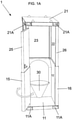
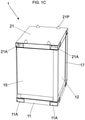
- Figures 1A , 1B and 1C show a first preferred embodiment of a housing for a sanitary facility 1 according to the invention in various positions.
- Figure 1A shows sanitary facility 1 with open door in position of use.
- Figure 1B shows sanitary facility 1 with closed door, likewise in position of use, and
- figure 1C shows sanitary facility 1 with closed door in rest position.
- Sanitary facility 1 comprises two housing parts slidable relative to each other.
- a first housing part 10 comprises a bottom 11 from which first wall segments 12, 13 and 14 extend.
- First housing part 10 further comprises a first door segment 15.
- a second housing part 20 comprises a roof or cover 21 from which second wall segments 22, 23 and 24 extend.
- Second housing part 20 further comprises a second door segment 25.
- wall segments 12, 22 form a side wall, as do wall segments 14, 24.
- Wall segments 13, 23 form a rear wall.
- the sanitary facility is intended for use as toilet.
- a receptacle 30 for human excrement and/or urine is arranged for this purpose in first housing part 10. Receptacle 30 is placed against first wall segment 13 of the rear wall.
- first door segment 15 takes a hollow form and second door segment 25 is received slidably in the first door segment.
- first wall segments 12 and 14 also take a hollow form, and the respective second wall segments 22 and 24 are received slidably therein.
- Second wall segment 23 preferably slides along first wall segment 13.
- First door segment 15 is mounted pivotally on first housing part 10 and second door segment 25 is mounted pivotally on second housing part 20. In the position of use the door is thereby a hinged door pivotable between the open position in figure 1A and the closed position in figure 1B .
- first tube segments 12, 13 and 13, 14 in first housing part 10 are mutually connected by respective first tube segments 17 and 18.
- Respective adjacent second wall segments 22, 23 and 23, 24 in second housing part 20 are likewise mutually connected by means of respective second tube segments 27 and 28.
- a first tube segment 16 is likewise situated on the front side between first door segment 15 and first wall segment 12.
- a second tube segment 26 is arranged between second door segment 25 and second wall segment 22.
- First door segment 15 is mounted on a first tube segment 19 arranged adjacently of first wall segment 14.
- Second door segment 25 is mounted on a second tube segment 29 arranged adjacently of second wall segment 24.
- First tube segments 16, 17, 18, 19 take a hollow form and second tube segments 26, 27, 28, 29 are received slidably therein.
- Sanitary facility 1 was developed to be moved between the rest position and the position of use by one person using mechanical aids.
- roof 21 of sanitary facility 1 is provided with openings 21A for receiving the forks of a forklift truck. Openings 21A are intended for sliding of second housing part 20 relative to first housing part 10.
- Bottom 11 is likewise provided with openings 11A for receiving the forks of the forklift truck. Openings 11A are intended for transport of the whole sanitary facility 1 in the rest position.
- a mechanical drive such as a spindle
- a spindle can be arranged in sanitary facility 1 as an alternative to using a forklift truck.
- One or more spindles can for instance be accommodated in the tubes.
- Sanitary facility 1 is provided with locking means for locking second housing part 20 relative to first housing part 10 in the position of use.
- Diverse locking means which are per se known in the relevant field, can be applied for this purpose.
- First housing part 10 is further provided with arresting means for arresting first door segment 15 relative to first wall segment 12, particularly first tube segment 16, in the closed position of the door.
- roof 21 Arranged on roof 21 are positioning elements in the form of protrusions 21P for stacking sanitary facilities 1 in the rest position. Bottom 11 of the sanitary facility is optionally provided with recesses (not shown) co-acting with the positioning protrusions.
- Figure 1D shows sanitary facility 1 in the position of use with open door from a different angle.
- Figures 1E-H show parts of figure 1D on enlarged scale.
- the door of sanitary facility 1 is provided with a lock 33 which can be arranged as desired on lower door segment 15 or on upper door segment 25.
- Lock 33 can, as desired, be a mortice lock or a rim lock.
- FIGS 1E, 1F and 1G show schematic views to illustrate the pivoting movement S of the door.
- the door segment has been broken away.
- Sanitary facility 1 comprises a pivot pin consisting of two parts. Upper part 35 of the pivot pin extends in upper door segment 25 and is fixed to a bearing block 36 in roof 21. Lower part 34 of the pivot pin extends in lower door segment 15 and is mounted on a bearing block 37 in bottom 11. Upper part 35 of the pivot pin is preferably received slidably in lower part 34.
- Figure 1H illustrates a cross-section through a side wall with the hollow first wall segment 12, in which second wall segment 22 is slidably received.
- the housing of sanitary facility 1 has a generally rectangular cross-section.
- the wall segments of sanitary facility 1 form a frame with a generally U-shaped cross-section.
- This U-shaped frame is preferably embodied in metal.
- the door segments are preferably embodied in plastic material.
- receptacles 30 can be connectable to a waste pipe for connection to a sewage system.
- first housing part 10 is provided with a storage reservoir (not shown) to which receptacles 30 are connected.
- the storage reservoir can be accommodated in bottom 11.
- Figures 2A , 2B and 2C show a second preferred embodiment of a housing 101 according to the invention in various positions.
- Figure 2A shows housing 101 with open door in position of use.
- Figure 2B shows housing 101 with closed door, likewise in position of use, and
- figure 2C shows housing 101 with closed door in rest position.
- Housing 101 is intended and suitable for use as sanitary facility.
- Housing 101 is a cabin, more particularly a single-person cabin, in which desired sanitary fixtures can be arranged, such as a receptacle, a sink or a shower.
- Cabin 101 can however also be configured for a different application, for instance as changing facility or box office booth.
- Cabin 101 comprises two housing parts 110, 120 which are slidable relative to each other.
- a first housing part 110 comprises a bottom 111 from which first wall segments 112, 113 and 114 extend.
- First housing part 110 further comprises a first door segment 115.
- a second housing part 120 comprises a roof or cover 121 from which second wall segments 122, 123 and 124 extend.
- Second housing part 120 further comprises a second door segment 125.
- first door segment 115 takes a hollow form and second door segment 125 is received slidably in the first door segment.
- the second wall segments 122, 123 and 124 slide along first wall segments 112, 113 and 114.
- first housing part 110 respective adjacent first wall segments 112, 113 and 113, 114 are mutually connected by respective first tubular segments 117 and 118.
- second housing part 120 respective adjacent second wall segments 122, 123 and 123, 124 are likewise mutually connected by means of respective second tube segments 127 and 128.
- a first tubular segment 116 is likewise situated on the front side between first door segment 115 and first wall segment 112.
- second housing part 120 a second tube segment 126 is arranged between second door segment 125 and second wall segment 122.
- First door segment 115 is mounted on a first tubular segment 119 which is arranged adjacently of first wall segment 114.
- Second door segment 125 is mounted on a second tube segment 129 arranged adjacently of second wall segment 124.
- the first tubular segments 116, 117, 118, 119 take a hollow form and the second tube segments 126, 127, 128, 129 are received slidably therein.
- First tubular segments 116, 117, 118, 119 further take a partially open form so as to enable movement of the second wall segments along the first wall segments.
- First tubular segments 116, 117, 118, 119 can be preformed in the first wall segments.
- tubular segments 116, 117, 118, 119 function as first tubes for receiving second tube segments 126, 127, 128, 129.
- locking means 140 Arranged on all first tubular segments 116, 117, 118, 119 are locking means 140 which are configured to lock the respective second tube segment therein.
- FIG. 2D shows locking means 140 for locking cabin 101 in the position of use of figure 2A in more detail.
- Locking means 140 comprise a locking element 141 which is arranged on first tubular segment 116 by means of a flexible attachment 143.
- First tubular segment 116 is further provided with a first opening 142 for receiving locking element 141.
- Second tube segment 126 is provided with a second opening which, in the position of use of cabin 101, lies in line with the first opening 142 for receiving locking element 141.
- Cabin 101 is further provided with a lock 132.
- lock 132 is a sliding lock for mutually locking first tubular segment 116 and first door segment 115.
- Cabin 101 is preferably embodied in metal, more preferably aluminium.
- a skylight 160 is arranged in the roof.
- a connection 131 for supply and discharge of (waste) water.
- the other technical measures of cabin 101 correspond to the technical measures of the housing of sanitary facility 1, as described above. All corresponding reference numerals are increased by 100.
- cabin 101 is configured for coupling to an adjoining cabin.
- Figures 3A and 3B illustrate an assembly of two coupled cabins 101 in respectively the position of use and the rest position.
- FIGs 3C and 3D show coupling means 150 for coupling the cabins 101 of figure 3A in more detail.
- Figure 3D shows coupling means 150 in assembled state.
- Figure 3E shows coupling means 150 with exploded parts.
- Coupling means 150 form a bolt-nut connection with a bolt 151 and a nut 152. The bolt is fastened fixedly to a coupling plate 153.
- a clamping foot 154 is further provided.
- Cabins 101 are each provided with a number of openings 155 for receiving bolts 151. In the shown preferred embodiment openings 155 are arranged on the sides of roof 121 and on the sides of floor 111. The holes preferably debouch into openings 121A and 111A for co-action with the forks of a forklift truck, which provide space for assembly.
- Cabins 101 are configured such that in coupled state they can be together connected to water, electrics and/or a sewer system. Connections 131 are preferably mutually connectable to a shared pump with shredding unit. The cabins are further preferably connected to a shared supply container with water. Such equipment is preferably accommodated in a separate housing, which can be added to the assembly.
- the present invention relates to a mobile retractable housing forming a closable accommodation for one person.
- a plurality of housings according to the invention can be coupled to form an assembly.
- the invention is expressly not limited to the shown and described preferred embodiments. Other variants in form and dimensions of the housing lie within the reach of a skilled person in the field on the basis of this text.
- Other or additional coupling means for coupling the housings to form an assembly comprise a frame in which the assembly can be placed, or aligning elements, such as box girders, with which to align and connect the housings in an assembly.
Landscapes
- Public Health (AREA)
- Health & Medical Sciences (AREA)
- Engineering & Computer Science (AREA)
- Architecture (AREA)
- Epidemiology (AREA)
- General Health & Medical Sciences (AREA)
- Civil Engineering (AREA)
- Structural Engineering (AREA)
- Hydrology & Water Resources (AREA)
- Water Supply & Treatment (AREA)
- Life Sciences & Earth Sciences (AREA)
- Residential Or Office Buildings (AREA)
- Housing For Livestock And Birds (AREA)
- Vehicle Waterproofing, Decoration, And Sanitation Devices (AREA)
- Wing Frames And Configurations (AREA)
- Body Structure For Vehicles (AREA)
Applications Claiming Priority (2)
| Application Number | Priority Date | Filing Date | Title |
|---|---|---|---|
| NL2015663A NL2015663B1 (nl) | 2015-10-26 | 2015-10-26 | Inschuifbare mobiele sanitaire voorziening met deur. |
| PCT/NL2016/050741 WO2017074182A1 (en) | 2015-10-26 | 2016-10-26 | Retractable mobile housing with door for a sanitary facility and an assembly of two or more coupled housings |
Publications (2)
| Publication Number | Publication Date |
|---|---|
| EP3368732A1 EP3368732A1 (en) | 2018-09-05 |
| EP3368732B1 true EP3368732B1 (en) | 2022-03-23 |
Family
ID=57354427
Family Applications (1)
| Application Number | Title | Priority Date | Filing Date |
|---|---|---|---|
| EP16798583.7A Active EP3368732B1 (en) | 2015-10-26 | 2016-10-26 | Retractable mobile housing with door for a sanitary facility and an assembly of two or more coupled housings |
Country Status (11)
| Country | Link |
|---|---|
| US (1) | US10724259B2 (pt) |
| EP (1) | EP3368732B1 (pt) |
| JP (1) | JP2018535341A (pt) |
| CN (1) | CN108699849A (pt) |
| AU (1) | AU2016345998B2 (pt) |
| CA (1) | CA3041028A1 (pt) |
| ES (1) | ES2923749T3 (pt) |
| NL (1) | NL2015663B1 (pt) |
| PT (1) | PT3368732T (pt) |
| RU (1) | RU2734487C2 (pt) |
| WO (1) | WO2017074182A1 (pt) |
Families Citing this family (9)
| Publication number | Priority date | Publication date | Assignee | Title |
|---|---|---|---|---|
| NL2022197B1 (nl) * | 2017-12-14 | 2019-06-25 | Mad Invest Bv | Transporteerbare sanitaire unit |
| WO2020163954A1 (en) * | 2019-02-15 | 2020-08-20 | Advantage Engineering Inc. | Collapsible toilet enclosure |
| US11166549B2 (en) * | 2019-05-07 | 2021-11-09 | Medal Technologies, LLC | Collapsible and stackable outdoor structure |
| US11166600B2 (en) * | 2019-08-29 | 2021-11-09 | Timothy Donald Blevins | Portable restroom system |
| CN110512700A (zh) * | 2019-09-29 | 2019-11-29 | 宁波市北仑森睿模具有限公司 | 一种伸缩式移动厕所 |
| US11808051B2 (en) * | 2020-04-20 | 2023-11-07 | Anthony Wang | Portable, modular, multi-purpose enclosure |
| GB202015540D0 (en) * | 2020-09-30 | 2020-11-11 | Lyons Ian | Collapsible structure |
| IT202100024176A1 (it) * | 2021-09-21 | 2023-03-21 | Starpool S R L | Cabina per trattamenti benessere, particolarmente saune, bagni turchi e simili |
| US12599274B2 (en) | 2022-11-18 | 2026-04-14 | David Perlman | Portable urinal for use with patients with limited mobility |
Family Cites Families (16)
| Publication number | Priority date | Publication date | Assignee | Title |
|---|---|---|---|---|
| US3774955A (en) * | 1970-06-10 | 1973-11-27 | J Byer | Mobile housing unit |
| US4844538A (en) * | 1988-04-20 | 1989-07-04 | Ricks Ronald S | Sunroof air deflector |
| US5379466A (en) * | 1993-09-30 | 1995-01-10 | Davies; Benjamin P. | Portable privacy closet |
| JPH1193434A (ja) * | 1997-09-22 | 1999-04-06 | Kimura Giken Kk | 簡易トイレ |
| NL1013604C2 (nl) * | 1999-11-18 | 2001-05-22 | Urilift Bv | Verzinkbare openbare sanitaire voorziening. |
| ZA200409806B (en) * | 2004-09-08 | 2006-05-31 | Christian George Frede Richter | Transportable toilet |
| DE202005009772U1 (de) * | 2005-06-22 | 2005-09-22 | Albers, Bernd | Zweischalen-Baustellen-WC |
| EP2114228A2 (en) * | 2007-01-17 | 2009-11-11 | Bradenfox Solutions LLC | Collapsible portable structure |
| US20090235445A1 (en) | 2008-03-24 | 2009-09-24 | Adam Goldstein | External urinal for portable toilets |
| US8770442B2 (en) * | 2010-06-04 | 2014-07-08 | Schroeder Industries, Inc. | O-ring retainer for valve stem |
| US20120037621A1 (en) * | 2010-08-13 | 2012-02-16 | Cantin Philip T | Mechanism for a container assembly |
| NZ628172A (en) * | 2012-02-17 | 2016-07-29 | Lifting Point Pty Ltd | Height adjustable shipping container |
| US9060652B2 (en) * | 2013-03-15 | 2015-06-23 | Marcel Adriaan Dirk Bikker | Transportable sanitary unit |
| JP5945980B2 (ja) * | 2014-03-05 | 2016-07-05 | キョーラク株式会社 | 仮設トイレユニット |
| CN204225521U (zh) * | 2014-09-18 | 2015-03-25 | 金朝阳 | 一种多功能卫生间 |
| CN204617713U (zh) * | 2015-03-20 | 2015-09-09 | 李晓晨 | 一种一体式伸缩摊位箱 |
-
2015
- 2015-10-26 NL NL2015663A patent/NL2015663B1/nl not_active IP Right Cessation
-
2016
- 2016-10-26 CA CA3041028A patent/CA3041028A1/en active Pending
- 2016-10-26 WO PCT/NL2016/050741 patent/WO2017074182A1/en not_active Ceased
- 2016-10-26 CN CN201680075099.9A patent/CN108699849A/zh active Pending
- 2016-10-26 AU AU2016345998A patent/AU2016345998B2/en not_active Ceased
- 2016-10-26 ES ES16798583T patent/ES2923749T3/es active Active
- 2016-10-26 PT PT167985837T patent/PT3368732T/pt unknown
- 2016-10-26 JP JP2018521097A patent/JP2018535341A/ja active Pending
- 2016-10-26 US US15/770,548 patent/US10724259B2/en active Active
- 2016-10-26 EP EP16798583.7A patent/EP3368732B1/en active Active
- 2016-10-26 RU RU2018119016A patent/RU2734487C2/ru active
Also Published As
| Publication number | Publication date |
|---|---|
| WO2017074182A1 (en) | 2017-05-04 |
| RU2734487C2 (ru) | 2020-10-19 |
| RU2018119016A3 (pt) | 2020-04-17 |
| PT3368732T (pt) | 2022-06-15 |
| ES2923749T3 (es) | 2022-09-30 |
| RU2018119016A (ru) | 2019-11-28 |
| CA3041028A1 (en) | 2017-05-04 |
| US10724259B2 (en) | 2020-07-28 |
| US20190063090A1 (en) | 2019-02-28 |
| AU2016345998A1 (en) | 2018-06-14 |
| EP3368732A1 (en) | 2018-09-05 |
| JP2018535341A (ja) | 2018-11-29 |
| NL2015663B1 (nl) | 2017-05-23 |
| CN108699849A (zh) | 2018-10-23 |
| AU2016345998B2 (en) | 2021-12-16 |
Similar Documents
| Publication | Publication Date | Title |
|---|---|---|
| EP3368732B1 (en) | Retractable mobile housing with door for a sanitary facility and an assembly of two or more coupled housings | |
| US7021010B2 (en) | Demountable building | |
| US9605424B2 (en) | Transportable sanitary unit | |
| US20080209624A1 (en) | Collapsible portable structure | |
| DK2780515T3 (en) | MOBILE SANITARY UNIT FOR APPLICATION OF AT LEAST THREE SANITARY PLANTS | |
| EP2657414B1 (en) | Transportable sanitary unit | |
| AU2002332957A1 (en) | Demountable building | |
| CA2892258A1 (en) | Transportable sanitary unit | |
| EP2913459A1 (en) | A kit for assembling mobile toilet facilities | |
| EP1801319B1 (de) | Hygienehaus | |
| CN111601937B (zh) | 可运输的卫生单元 | |
| DE3628691A1 (de) | Transportable kabine | |
| DE202018001431U1 (de) | Mobiler Sanitärkabinenkomplex | |
| KR20250076564A (ko) | 통합 프레임과 하중 지지 고정 및 리프팅 수단을 갖춘 원격 사이트 및 해상 복지 유닛 | |
| EP0313673A1 (de) | Transportable Kabine | |
| EP2835477B1 (de) | Mobile Badezimmereinheit | |
| KR102940040B1 (ko) | 이동식 화장실 | |
| DE102023127947A1 (de) | Baustellen-WC | |
| WO2025015239A1 (en) | Transportable, reconfigurable harsh environment workspace | |
| FR3109954A1 (fr) | Bloc sanitaire modulaire | |
| IT201800003087U1 (it) | Servizio igienico mobile multifunzionale | |
| ITRM980149U1 (it) | Impianto igienico-sanitario pubblico mobile |
Legal Events
| Date | Code | Title | Description |
|---|---|---|---|
| STAA | Information on the status of an ep patent application or granted ep patent |
Free format text: STATUS: UNKNOWN |
|
| STAA | Information on the status of an ep patent application or granted ep patent |
Free format text: STATUS: THE INTERNATIONAL PUBLICATION HAS BEEN MADE |
|
| PUAI | Public reference made under article 153(3) epc to a published international application that has entered the european phase |
Free format text: ORIGINAL CODE: 0009012 |
|
| STAA | Information on the status of an ep patent application or granted ep patent |
Free format text: STATUS: REQUEST FOR EXAMINATION WAS MADE |
|
| 17P | Request for examination filed |
Effective date: 20180524 |
|
| AK | Designated contracting states |
Kind code of ref document: A1 Designated state(s): AL AT BE BG CH CY CZ DE DK EE ES FI FR GB GR HR HU IE IS IT LI LT LU LV MC MK MT NL NO PL PT RO RS SE SI SK SM TR |
|
| AX | Request for extension of the european patent |
Extension state: BA ME |
|
| DAV | Request for validation of the european patent (deleted) | ||
| DAX | Request for extension of the european patent (deleted) | ||
| STAA | Information on the status of an ep patent application or granted ep patent |
Free format text: STATUS: EXAMINATION IS IN PROGRESS |
|
| 17Q | First examination report despatched |
Effective date: 20201216 |
|
| GRAP | Despatch of communication of intention to grant a patent |
Free format text: ORIGINAL CODE: EPIDOSNIGR1 |
|
| STAA | Information on the status of an ep patent application or granted ep patent |
Free format text: STATUS: GRANT OF PATENT IS INTENDED |
|
| GRAJ | Information related to disapproval of communication of intention to grant by the applicant or resumption of examination proceedings by the epo deleted |
Free format text: ORIGINAL CODE: EPIDOSDIGR1 |
|
| GRAP | Despatch of communication of intention to grant a patent |
Free format text: ORIGINAL CODE: EPIDOSNIGR1 |
|
| RIC1 | Information provided on ipc code assigned before grant |
Ipc: E03D 7/00 20060101ALI20210927BHEP Ipc: A47K 3/32 20060101ALI20210927BHEP Ipc: A47K 11/00 20060101ALI20210927BHEP Ipc: E04H 1/12 20060101AFI20210927BHEP |
|
| INTG | Intention to grant announced |
Effective date: 20211013 |
|
| INTG | Intention to grant announced |
Effective date: 20211027 |
|
| GRAS | Grant fee paid |
Free format text: ORIGINAL CODE: EPIDOSNIGR3 |
|
| GRAA | (expected) grant |
Free format text: ORIGINAL CODE: 0009210 |
|
| STAA | Information on the status of an ep patent application or granted ep patent |
Free format text: STATUS: THE PATENT HAS BEEN GRANTED |
|
| AK | Designated contracting states |
Kind code of ref document: B1 Designated state(s): AL AT BE BG CH CY CZ DE DK EE ES FI FR GB GR HR HU IE IS IT LI LT LU LV MC MK MT NL NO PL PT RO RS SE SI SK SM TR |
|
| REG | Reference to a national code |
Ref country code: GB Ref legal event code: FG4D |
|
| REG | Reference to a national code |
Ref country code: CH Ref legal event code: EP |
|
| REG | Reference to a national code |
Ref country code: IE Ref legal event code: FG4D |
|
| REG | Reference to a national code |
Ref country code: DE Ref legal event code: R096 Ref document number: 602016070316 Country of ref document: DE |
|
| REG | Reference to a national code |
Ref country code: AT Ref legal event code: REF Ref document number: 1477532 Country of ref document: AT Kind code of ref document: T Effective date: 20220415 |
|
| REG | Reference to a national code |
Ref country code: NL Ref legal event code: FP |
|
| REG | Reference to a national code |
Ref country code: PT Ref legal event code: SC4A Ref document number: 3368732 Country of ref document: PT Date of ref document: 20220615 Kind code of ref document: T Free format text: AVAILABILITY OF NATIONAL TRANSLATION Effective date: 20220607 |
|
| REG | Reference to a national code |
Ref country code: LT Ref legal event code: MG9D |
|
| PG25 | Lapsed in a contracting state [announced via postgrant information from national office to epo] |
Ref country code: SE Free format text: LAPSE BECAUSE OF FAILURE TO SUBMIT A TRANSLATION OF THE DESCRIPTION OR TO PAY THE FEE WITHIN THE PRESCRIBED TIME-LIMIT Effective date: 20220323 Ref country code: RS Free format text: LAPSE BECAUSE OF FAILURE TO SUBMIT A TRANSLATION OF THE DESCRIPTION OR TO PAY THE FEE WITHIN THE PRESCRIBED TIME-LIMIT Effective date: 20220323 Ref country code: NO Free format text: LAPSE BECAUSE OF FAILURE TO SUBMIT A TRANSLATION OF THE DESCRIPTION OR TO PAY THE FEE WITHIN THE PRESCRIBED TIME-LIMIT Effective date: 20220623 Ref country code: LT Free format text: LAPSE BECAUSE OF FAILURE TO SUBMIT A TRANSLATION OF THE DESCRIPTION OR TO PAY THE FEE WITHIN THE PRESCRIBED TIME-LIMIT Effective date: 20220323 Ref country code: HR Free format text: LAPSE BECAUSE OF FAILURE TO SUBMIT A TRANSLATION OF THE DESCRIPTION OR TO PAY THE FEE WITHIN THE PRESCRIBED TIME-LIMIT Effective date: 20220323 Ref country code: BG Free format text: LAPSE BECAUSE OF FAILURE TO SUBMIT A TRANSLATION OF THE DESCRIPTION OR TO PAY THE FEE WITHIN THE PRESCRIBED TIME-LIMIT Effective date: 20220623 |
|
| REG | Reference to a national code |
Ref country code: AT Ref legal event code: MK05 Ref document number: 1477532 Country of ref document: AT Kind code of ref document: T Effective date: 20220323 |
|
| PG25 | Lapsed in a contracting state [announced via postgrant information from national office to epo] |
Ref country code: LV Free format text: LAPSE BECAUSE OF FAILURE TO SUBMIT A TRANSLATION OF THE DESCRIPTION OR TO PAY THE FEE WITHIN THE PRESCRIBED TIME-LIMIT Effective date: 20220323 Ref country code: GR Free format text: LAPSE BECAUSE OF FAILURE TO SUBMIT A TRANSLATION OF THE DESCRIPTION OR TO PAY THE FEE WITHIN THE PRESCRIBED TIME-LIMIT Effective date: 20220624 Ref country code: FI Free format text: LAPSE BECAUSE OF FAILURE TO SUBMIT A TRANSLATION OF THE DESCRIPTION OR TO PAY THE FEE WITHIN THE PRESCRIBED TIME-LIMIT Effective date: 20220323 |
|
| REG | Reference to a national code |
Ref country code: ES Ref legal event code: FG2A Ref document number: 2923749 Country of ref document: ES Kind code of ref document: T3 Effective date: 20220930 |
|
| PG25 | Lapsed in a contracting state [announced via postgrant information from national office to epo] |
Ref country code: SM Free format text: LAPSE BECAUSE OF FAILURE TO SUBMIT A TRANSLATION OF THE DESCRIPTION OR TO PAY THE FEE WITHIN THE PRESCRIBED TIME-LIMIT Effective date: 20220323 Ref country code: SK Free format text: LAPSE BECAUSE OF FAILURE TO SUBMIT A TRANSLATION OF THE DESCRIPTION OR TO PAY THE FEE WITHIN THE PRESCRIBED TIME-LIMIT Effective date: 20220323 Ref country code: RO Free format text: LAPSE BECAUSE OF FAILURE TO SUBMIT A TRANSLATION OF THE DESCRIPTION OR TO PAY THE FEE WITHIN THE PRESCRIBED TIME-LIMIT Effective date: 20220323 Ref country code: EE Free format text: LAPSE BECAUSE OF FAILURE TO SUBMIT A TRANSLATION OF THE DESCRIPTION OR TO PAY THE FEE WITHIN THE PRESCRIBED TIME-LIMIT Effective date: 20220323 Ref country code: CZ Free format text: LAPSE BECAUSE OF FAILURE TO SUBMIT A TRANSLATION OF THE DESCRIPTION OR TO PAY THE FEE WITHIN THE PRESCRIBED TIME-LIMIT Effective date: 20220323 Ref country code: AT Free format text: LAPSE BECAUSE OF FAILURE TO SUBMIT A TRANSLATION OF THE DESCRIPTION OR TO PAY THE FEE WITHIN THE PRESCRIBED TIME-LIMIT Effective date: 20220323 |
|
| PG25 | Lapsed in a contracting state [announced via postgrant information from national office to epo] |
Ref country code: PL Free format text: LAPSE BECAUSE OF FAILURE TO SUBMIT A TRANSLATION OF THE DESCRIPTION OR TO PAY THE FEE WITHIN THE PRESCRIBED TIME-LIMIT Effective date: 20220323 Ref country code: IS Free format text: LAPSE BECAUSE OF FAILURE TO SUBMIT A TRANSLATION OF THE DESCRIPTION OR TO PAY THE FEE WITHIN THE PRESCRIBED TIME-LIMIT Effective date: 20220723 Ref country code: AL Free format text: LAPSE BECAUSE OF FAILURE TO SUBMIT A TRANSLATION OF THE DESCRIPTION OR TO PAY THE FEE WITHIN THE PRESCRIBED TIME-LIMIT Effective date: 20220323 |
|
| REG | Reference to a national code |
Ref country code: DE Ref legal event code: R097 Ref document number: 602016070316 Country of ref document: DE |
|
| PLBE | No opposition filed within time limit |
Free format text: ORIGINAL CODE: 0009261 |
|
| STAA | Information on the status of an ep patent application or granted ep patent |
Free format text: STATUS: NO OPPOSITION FILED WITHIN TIME LIMIT |
|
| PG25 | Lapsed in a contracting state [announced via postgrant information from national office to epo] |
Ref country code: DK Free format text: LAPSE BECAUSE OF FAILURE TO SUBMIT A TRANSLATION OF THE DESCRIPTION OR TO PAY THE FEE WITHIN THE PRESCRIBED TIME-LIMIT Effective date: 20220323 |
|
| 26N | No opposition filed |
Effective date: 20230102 |
|
| PG25 | Lapsed in a contracting state [announced via postgrant information from national office to epo] |
Ref country code: SI Free format text: LAPSE BECAUSE OF FAILURE TO SUBMIT A TRANSLATION OF THE DESCRIPTION OR TO PAY THE FEE WITHIN THE PRESCRIBED TIME-LIMIT Effective date: 20220323 Ref country code: MC Free format text: LAPSE BECAUSE OF FAILURE TO SUBMIT A TRANSLATION OF THE DESCRIPTION OR TO PAY THE FEE WITHIN THE PRESCRIBED TIME-LIMIT Effective date: 20220323 |
|
| REG | Reference to a national code |
Ref country code: CH Ref legal event code: PL |
|
| PG25 | Lapsed in a contracting state [announced via postgrant information from national office to epo] |
Ref country code: LU Free format text: LAPSE BECAUSE OF NON-PAYMENT OF DUE FEES Effective date: 20221026 |
|
| P01 | Opt-out of the competence of the unified patent court (upc) registered |
Effective date: 20230531 |
|
| PG25 | Lapsed in a contracting state [announced via postgrant information from national office to epo] |
Ref country code: LI Free format text: LAPSE BECAUSE OF NON-PAYMENT OF DUE FEES Effective date: 20221031 Ref country code: CH Free format text: LAPSE BECAUSE OF NON-PAYMENT OF DUE FEES Effective date: 20221031 |
|
| PG25 | Lapsed in a contracting state [announced via postgrant information from national office to epo] |
Ref country code: PT Free format text: LAPSE BECAUSE OF NON-PAYMENT OF DUE FEES Effective date: 20230726 Ref country code: IE Free format text: LAPSE BECAUSE OF NON-PAYMENT OF DUE FEES Effective date: 20221026 |
|
| PG25 | Lapsed in a contracting state [announced via postgrant information from national office to epo] |
Ref country code: HU Free format text: LAPSE BECAUSE OF FAILURE TO SUBMIT A TRANSLATION OF THE DESCRIPTION OR TO PAY THE FEE WITHIN THE PRESCRIBED TIME-LIMIT; INVALID AB INITIO Effective date: 20161026 |
|
| PG25 | Lapsed in a contracting state [announced via postgrant information from national office to epo] |
Ref country code: CY Free format text: LAPSE BECAUSE OF FAILURE TO SUBMIT A TRANSLATION OF THE DESCRIPTION OR TO PAY THE FEE WITHIN THE PRESCRIBED TIME-LIMIT Effective date: 20220323 |
|
| PG25 | Lapsed in a contracting state [announced via postgrant information from national office to epo] |
Ref country code: MK Free format text: LAPSE BECAUSE OF FAILURE TO SUBMIT A TRANSLATION OF THE DESCRIPTION OR TO PAY THE FEE WITHIN THE PRESCRIBED TIME-LIMIT Effective date: 20220323 |
|
| PG25 | Lapsed in a contracting state [announced via postgrant information from national office to epo] |
Ref country code: TR Free format text: LAPSE BECAUSE OF FAILURE TO SUBMIT A TRANSLATION OF THE DESCRIPTION OR TO PAY THE FEE WITHIN THE PRESCRIBED TIME-LIMIT Effective date: 20220323 |
|
| PG25 | Lapsed in a contracting state [announced via postgrant information from national office to epo] |
Ref country code: MT Free format text: LAPSE BECAUSE OF FAILURE TO SUBMIT A TRANSLATION OF THE DESCRIPTION OR TO PAY THE FEE WITHIN THE PRESCRIBED TIME-LIMIT Effective date: 20220323 |
|
| REG | Reference to a national code |
Ref country code: DE Ref legal event code: R081 Ref document number: 602016070316 Country of ref document: DE Owner name: POP-UP TOILET EVENTS B.V., NL Free format text: FORMER OWNER: URILIFT BEHEER B.V., BEEMTE-BROEKLAND, NL |
|
| REG | Reference to a national code |
Ref country code: NL Ref legal event code: PD Owner name: POP-UP TOILET EVENTS B.V.; NL Free format text: DETAILS ASSIGNMENT: CHANGE OF OWNER(S), ASSIGNMENT; FORMER OWNER NAME: URILIFT BEHEER B.V. Effective date: 20241104 |
|
| REG | Reference to a national code |
Ref country code: GB Ref legal event code: 732E Free format text: REGISTERED BETWEEN 20241031 AND 20241106 |
|
| REG | Reference to a national code |
Ref country code: BE Ref legal event code: PD Owner name: POP-UP TOILET EVENTS B.V.; NL Free format text: DETAILS ASSIGNMENT: CHANGE OF OWNER(S), ASSIGNMENT; FORMER OWNER NAME: URILIFT BEHEER B.V. Effective date: 20241031 |
|
| REG | Reference to a national code |
Ref country code: ES Ref legal event code: PC2A Owner name: POP-UP TOILET EVENTS B.V. Effective date: 20250210 |
|
| PGFP | Annual fee paid to national office [announced via postgrant information from national office to epo] |
Ref country code: NL Payment date: 20251025 Year of fee payment: 10 |
|
| PGFP | Annual fee paid to national office [announced via postgrant information from national office to epo] |
Ref country code: DE Payment date: 20251027 Year of fee payment: 10 |
|
| PGFP | Annual fee paid to national office [announced via postgrant information from national office to epo] |
Ref country code: GB Payment date: 20251025 Year of fee payment: 10 |
|
| PGFP | Annual fee paid to national office [announced via postgrant information from national office to epo] |
Ref country code: IT Payment date: 20251024 Year of fee payment: 10 |
|
| PGFP | Annual fee paid to national office [announced via postgrant information from national office to epo] |
Ref country code: FR Payment date: 20251025 Year of fee payment: 10 |
|
| PGFP | Annual fee paid to national office [announced via postgrant information from national office to epo] |
Ref country code: BE Payment date: 20251027 Year of fee payment: 10 |
|
| PGFP | Annual fee paid to national office [announced via postgrant information from national office to epo] |
Ref country code: ES Payment date: 20251110 Year of fee payment: 10 |