EP3368805B1 - Flexibler schlauch - Google Patents
Flexibler schlauch Download PDFInfo
- Publication number
- EP3368805B1 EP3368805B1 EP16815636.2A EP16815636A EP3368805B1 EP 3368805 B1 EP3368805 B1 EP 3368805B1 EP 16815636 A EP16815636 A EP 16815636A EP 3368805 B1 EP3368805 B1 EP 3368805B1
- Authority
- EP
- European Patent Office
- Prior art keywords
- tubular element
- flexible hose
- troughs
- crests
- polymeric material
- Prior art date
- Legal status (The legal status is an assumption and is not a legal conclusion. Google has not performed a legal analysis and makes no representation as to the accuracy of the status listed.)
- Active
Links
Images



Classifications
-
- F—MECHANICAL ENGINEERING; LIGHTING; HEATING; WEAPONS; BLASTING
- F16—ENGINEERING ELEMENTS AND UNITS; GENERAL MEASURES FOR PRODUCING AND MAINTAINING EFFECTIVE FUNCTIONING OF MACHINES OR INSTALLATIONS; THERMAL INSULATION IN GENERAL
- F16L—PIPES; JOINTS OR FITTINGS FOR PIPES; SUPPORTS FOR PIPES, CABLES OR PROTECTIVE TUBING; MEANS FOR THERMAL INSULATION IN GENERAL
- F16L11/00—Hoses, i.e. flexible pipes
- F16L11/04—Hoses, i.e. flexible pipes made of rubber or flexible plastics
- F16L11/11—Hoses, i.e. flexible pipes made of rubber or flexible plastics with corrugated wall
- F16L11/112—Hoses, i.e. flexible pipes made of rubber or flexible plastics with corrugated wall having reinforcements embedded in the wall
-
- F—MECHANICAL ENGINEERING; LIGHTING; HEATING; WEAPONS; BLASTING
- F16—ENGINEERING ELEMENTS AND UNITS; GENERAL MEASURES FOR PRODUCING AND MAINTAINING EFFECTIVE FUNCTIONING OF MACHINES OR INSTALLATIONS; THERMAL INSULATION IN GENERAL
- F16L—PIPES; JOINTS OR FITTINGS FOR PIPES; SUPPORTS FOR PIPES, CABLES OR PROTECTIVE TUBING; MEANS FOR THERMAL INSULATION IN GENERAL
- F16L11/00—Hoses, i.e. flexible pipes
- F16L11/04—Hoses, i.e. flexible pipes made of rubber or flexible plastics
- F16L11/08—Hoses, i.e. flexible pipes made of rubber or flexible plastics with reinforcements embedded in the wall
-
- B—PERFORMING OPERATIONS; TRANSPORTING
- B29—WORKING OF PLASTICS; WORKING OF SUBSTANCES IN A PLASTIC STATE IN GENERAL
- B29C—SHAPING OR JOINING OF PLASTICS; SHAPING OF MATERIAL IN A PLASTIC STATE, NOT OTHERWISE PROVIDED FOR; AFTER-TREATMENT OF THE SHAPED PRODUCTS, e.g. REPAIRING
- B29C48/00—Extrusion moulding, i.e. expressing the moulding material through a die or nozzle which imparts the desired form; Apparatus therefor
- B29C48/001—Combinations of extrusion moulding with other shaping operations
- B29C48/0019—Combinations of extrusion moulding with other shaping operations combined with shaping by flattening, folding or bending
-
- B—PERFORMING OPERATIONS; TRANSPORTING
- B29—WORKING OF PLASTICS; WORKING OF SUBSTANCES IN A PLASTIC STATE IN GENERAL
- B29C—SHAPING OR JOINING OF PLASTICS; SHAPING OF MATERIAL IN A PLASTIC STATE, NOT OTHERWISE PROVIDED FOR; AFTER-TREATMENT OF THE SHAPED PRODUCTS, e.g. REPAIRING
- B29C48/00—Extrusion moulding, i.e. expressing the moulding material through a die or nozzle which imparts the desired form; Apparatus therefor
- B29C48/03—Extrusion moulding, i.e. expressing the moulding material through a die or nozzle which imparts the desired form; Apparatus therefor characterised by the shape of the extruded material at extrusion
- B29C48/09—Articles with cross-sections having partially or fully enclosed cavities, e.g. pipes or channels
- B29C48/10—Articles with cross-sections having partially or fully enclosed cavities, e.g. pipes or channels flexible, e.g. blown foils
-
- B—PERFORMING OPERATIONS; TRANSPORTING
- B29—WORKING OF PLASTICS; WORKING OF SUBSTANCES IN A PLASTIC STATE IN GENERAL
- B29C—SHAPING OR JOINING OF PLASTICS; SHAPING OF MATERIAL IN A PLASTIC STATE, NOT OTHERWISE PROVIDED FOR; AFTER-TREATMENT OF THE SHAPED PRODUCTS, e.g. REPAIRING
- B29C48/00—Extrusion moulding, i.e. expressing the moulding material through a die or nozzle which imparts the desired form; Apparatus therefor
- B29C48/16—Articles comprising two or more components, e.g. co-extruded layers
- B29C48/18—Articles comprising two or more components, e.g. co-extruded layers the components being layers
- B29C48/21—Articles comprising two or more components, e.g. co-extruded layers the components being layers the layers being joined at their surfaces
-
- B—PERFORMING OPERATIONS; TRANSPORTING
- B29—WORKING OF PLASTICS; WORKING OF SUBSTANCES IN A PLASTIC STATE IN GENERAL
- B29C—SHAPING OR JOINING OF PLASTICS; SHAPING OF MATERIAL IN A PLASTIC STATE, NOT OTHERWISE PROVIDED FOR; AFTER-TREATMENT OF THE SHAPED PRODUCTS, e.g. REPAIRING
- B29C53/00—Shaping by bending, folding, twisting, straightening or flattening; Apparatus therefor
- B29C53/22—Corrugating
- B29C53/30—Corrugating of tubes
-
- B—PERFORMING OPERATIONS; TRANSPORTING
- B32—LAYERED PRODUCTS
- B32B—LAYERED PRODUCTS, i.e. PRODUCTS BUILT-UP OF STRATA OF FLAT OR NON-FLAT, e.g. CELLULAR OR HONEYCOMB, FORM
- B32B1/00—Layered products having a non-planar shape
- B32B1/08—Tubular products
-
- B—PERFORMING OPERATIONS; TRANSPORTING
- B32—LAYERED PRODUCTS
- B32B—LAYERED PRODUCTS, i.e. PRODUCTS BUILT-UP OF STRATA OF FLAT OR NON-FLAT, e.g. CELLULAR OR HONEYCOMB, FORM
- B32B27/00—Layered products comprising a layer of synthetic resin
- B32B27/06—Layered products comprising a layer of synthetic resin as the main or only constituent of a layer, which is next to another layer of the same or of a different material
- B32B27/08—Layered products comprising a layer of synthetic resin as the main or only constituent of a layer, which is next to another layer of the same or of a different material of synthetic resin
-
- B—PERFORMING OPERATIONS; TRANSPORTING
- B32—LAYERED PRODUCTS
- B32B—LAYERED PRODUCTS, i.e. PRODUCTS BUILT-UP OF STRATA OF FLAT OR NON-FLAT, e.g. CELLULAR OR HONEYCOMB, FORM
- B32B3/00—Layered products comprising a layer with external or internal discontinuities or unevennesses, or a layer of non-planar shape; Layered products comprising a layer having particular features of form
- B32B3/26—Layered products comprising a layer with external or internal discontinuities or unevennesses, or a layer of non-planar shape; Layered products comprising a layer having particular features of form characterised by a particular shape of the outline of the cross-section of a continuous layer; characterised by a layer with cavities or internal voids ; characterised by an apertured layer
- B32B3/28—Layered products comprising a layer with external or internal discontinuities or unevennesses, or a layer of non-planar shape; Layered products comprising a layer having particular features of form characterised by a particular shape of the outline of the cross-section of a continuous layer; characterised by a layer with cavities or internal voids ; characterised by an apertured layer characterised by a layer comprising a deformed thin sheet, i.e. the layer having its entire thickness deformed out of the plane, e.g. corrugated, crumpled
-
- F—MECHANICAL ENGINEERING; LIGHTING; HEATING; WEAPONS; BLASTING
- F16—ENGINEERING ELEMENTS AND UNITS; GENERAL MEASURES FOR PRODUCING AND MAINTAINING EFFECTIVE FUNCTIONING OF MACHINES OR INSTALLATIONS; THERMAL INSULATION IN GENERAL
- F16L—PIPES; JOINTS OR FITTINGS FOR PIPES; SUPPORTS FOR PIPES, CABLES OR PROTECTIVE TUBING; MEANS FOR THERMAL INSULATION IN GENERAL
- F16L11/00—Hoses, i.e. flexible pipes
- F16L11/04—Hoses, i.e. flexible pipes made of rubber or flexible plastics
- F16L11/11—Hoses, i.e. flexible pipes made of rubber or flexible plastics with corrugated wall
-
- F—MECHANICAL ENGINEERING; LIGHTING; HEATING; WEAPONS; BLASTING
- F16—ENGINEERING ELEMENTS AND UNITS; GENERAL MEASURES FOR PRODUCING AND MAINTAINING EFFECTIVE FUNCTIONING OF MACHINES OR INSTALLATIONS; THERMAL INSULATION IN GENERAL
- F16L—PIPES; JOINTS OR FITTINGS FOR PIPES; SUPPORTS FOR PIPES, CABLES OR PROTECTIVE TUBING; MEANS FOR THERMAL INSULATION IN GENERAL
- F16L11/00—Hoses, i.e. flexible pipes
- F16L11/04—Hoses, i.e. flexible pipes made of rubber or flexible plastics
- F16L11/11—Hoses, i.e. flexible pipes made of rubber or flexible plastics with corrugated wall
- F16L11/115—Hoses, i.e. flexible pipes made of rubber or flexible plastics with corrugated wall having reinforcements not embedded in the wall
-
- B—PERFORMING OPERATIONS; TRANSPORTING
- B32—LAYERED PRODUCTS
- B32B—LAYERED PRODUCTS, i.e. PRODUCTS BUILT-UP OF STRATA OF FLAT OR NON-FLAT, e.g. CELLULAR OR HONEYCOMB, FORM
- B32B2597/00—Tubular articles, e.g. hoses, pipes
Definitions
- the present invention concerns a flexible hose. More in particular, the present invention concerns a flexible hose preferably, but not exclusively, for use in activities such as gardening and the like.
- hoses which combine a good performance with a relatively low cost.
- this type of hoses has gradually evolved to get the best performances under different conditions of use.
- hoses comprising more layers have been devised, each of which is intended to have a specific function, for example the function of outer coating, or of direct contacting with the fluid or of barrier against the growth of algae or other similar organisms.
- the reinforcement layer can be constituted for example by a net or a fabric of polymeric material that wraps an underlying layer of the hose, and on which an additional external protective layer is optionally applied.
- Patent application GB 1506776 describes, for example, a flexible hose comprising an inner layer of corrugated thermoplastic material; a layer of deformable material that covers the inner corrugated layer; and an outer reinforcement layer of textile knitting or metal net placed in contact with the coating layer.
- the inner corrugated layer externally defines annular cavities with a substantially trapezoidal profile, which are filled by said layer of deformable material.
- hoses of this type can also reach some tens of meters in length; consequently, the weight of a single hose can be high and thus difficult for the user to move easily.
- the task of the present invention is to solve the aforementioned problems, devising a flexible hose having great lightness.
- Another scope of the invention is to provide a flexible hose of simple constructive and functional conception, provided with surely reliable functioning, versatile use and relatively economic cost.
- the flexible hose comprises a fist tubular element of corrugated shape having in longitudinal cross-section a series of outer crests having triangular profile, so as to be axially flexible, and a second tubular element of lightweight material externally associated with said first tubular element so as to fill at least partially a corresponding series of troughs alternately shaped by said outer crests.
- Said first tubular element of corrugated shape shapes a sort of bellow.
- said outer crests of said first tubular element have a scalene triangle shape.
- the pitch of said outer crests is equal to about one-third of the internal diameter of the hose.
- Said lightweight polymeric material of said second tubular element partially fills said series of troughs alternately shaped between said outer crests, so as to define on the bottom of said troughs a corresponding series of chambers of annular shape.
- said chambers of annular shape are obtained in sealing between said first tubular element and said second tubular element.
- said first tubular element is made of substantially rigid polymeric material.
- said first tubular element is made of a material of the type of PVC, PU, PET and the like, or by a mixture of the aforementioned materials.
- said second tubular element is made of a lightweight material selected among a polymeric material, a foam material, a vulcanized and/or low density rubber, or a mixture of the aforementioned materials.
- said second tubular element is externally associated with said first tubular element through co-extrusion.
- said outer crests of said first tubular element have, in extended configuration, a pitch of approximately one-third of the internal diameter of the same first tubular element.
- said outer crests of said first tubular element have respective cavities aligned so as to define at least one groove longitudinal to said first tubular element.
- a filiform reinforcement element predisposed to be embedded in said lightweight polymeric material of said second tubular element.
- the flexible hose comprises an external coating layer overlapped to said second tubular element.
- the flexible hose comprises a third tubular element of flexible material internally associated to said first tubular element so as to fill at least partially a corresponding series of troughs alternately shaped by the inner crests of said first tubular element.
- the flexible hose comprises an internal coating layer inserted inside said third tubular element.
- the present invention concerns as well a method for manufacturing a flexible hose which provides to form, through extrusion and subsequent corrugation, a first tubular element of corrugated shape having in longitudinal cross-section a series of outer crests with triangular profile; arranging, through a compacting device, said first tubular element in a compacted configuration; associating a second tubular element of lightweight material externally to said first compacted tubular element, through co-extrusion, so as to fill at least partially a corresponding series of troughs alternately shaped by said outer crests.
- said co-extrusion step of the second tubular element on the first compacted tubular element occurs in absence of air through the depression created by a vacuum pump working at the extrusion head.
- said depression created by the vacuum pump is predisposed to modulate the thickness of the coating of said second tubular element of lightweight material on said first tubular element.
- said depression created by the vacuum pump is predisposed to modulate the filling of said troughs with said second tubular element of lightweight material.
- the method provides to cool the hose obtained from said co-extrusion step.
- the method provides to perform the drawing of said hose at one end thereof so as to obtain the calibrated releasing of said compacted first tubular element.
- said compacting device performs a reduction of the line feeding speed of said first tubular element to a value equal to about one-third of the speed of entry inside the same compacting device, so as to cause a reduction of the pitch of said outer crests.
- the flexible hose according to the present invention is indicated in its entirety with 1.
- the flexible hose according to the invention is intended for use in the gardening field and the like. However, it is possible to intend its use also for other fields.
- the flexible hose 1 comprises a first flexible tubular element 2 of a corrugated type.
- the first tubular element 2 can be manufactured through a polymeric material of suitable mechanical properties, for example PVC, PU, PET and the like, or a mixture of the same materials.
- the first tubular element 2 can also be manufactured by co-extrusion, in more layers and with different materials.
- the flexible hose 1 comprises a second flexible tubular element 3.
- the second tubular element 3 is associated externally with the first tubular element 2.
- the second tubular element 3 is manufactured with a lightweight material selected among a polymeric material, a foam material, a vulcanized and/or low density rubber, or a mixture of the same materials.
- the second tubular element 3 is made of thermoplastic polymeric material with low density, with a foaming agent, or vulcanized and/or low density rubber with foaming agent.
- the foaming agent con be of any type, and for example in liquid or paste form, or with grains, powder and so on.
- the foaming agent during the expansion step, generates gases that spread within the polymeric matrix, forming a cell structure within the polymeric material.
- Such cell structure allows to obtain, for equal volume, a considerable lightening of the material.
- the formation of such a cell structure gives the material of the second tubular element 3 a substantially spongy or however widely porous consistency, characterized by a certain elasticity.
- the first corrugated tubular element 2 has in longitudinal cross-section a series of outer crests 4, having triangular profile, and a corresponding series of troughs 5 alternately shaped by said outer crests 4.
- the crests 4 and the troughs 5 give rise, at the inner side of the first corrugated tubular element 2, to a plurality of specular crests 6 and troughs 7.
- the outer crests 4 and the outer troughs 5 respectively correspond to the inner crests 6 and the inner troughs 7 of the first tubular element 2, so as to define a sort of bellows.
- the crests 4 and 6 of the first tubular element 2, respectively outer and inner, have a scalene triangle profile.
- the second tubular element 3 is associated with the first tubular element 2 so that the lightweight material fills at least partially the outer troughs 5 of the first tubular element 2.
- the second tubular element 3 is associated with the first tubular element 2 so that the lightweight material fills completely, and in uniform manner, the outer troughs 5 of the first tubular element 2. This allows to obtain an extended superficial adhesion between the two components that eliminates any detachments risk during use.
- the second tubular element 3 is associated with the first tubular element 2 so as to partially fill the troughs 5 alternately shaped by said outer crests 4, so as to define at the bottom of the same troughs 5 a corresponding series of chambers 15 of annular shape.
- the chambers 15 of annular shape are obtained in sealing between the first tubular element 2 and the second tubular element 3.
- the second tubular element 3 has a smooth or substantially smooth external surface 8. Therefore, the second tubular element 3 has a non-uniform outer thickness, and then does not follow the shape of the inner corrugated tubular element 2.
- the smooth or substantially smooth outer surface 8 of the second tubular element 3 prevents the hose 1 to collect dirt during use.
- the outer surface 8 of the second tubular element 3 may have non-smooth shape.
- the flexible hose 1 in use, can assume a curved configuration with respect of the longitudinal axis of the same hose.
- the second tubular element 3 shortens, that is, is compressed, from the inner side 9 of the hose with respect to the centre of curvature, while it extends, that is, is stretched at the outer side 10 with respect to the above-mentioned centre of curvature.
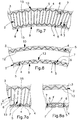
- the portions of material which fill the outer troughs 5 are compressed by the same outer crests 4 of the fist tubular element 2 which approach each other, as it is schematically indicated with arrows F in the detail of figure 7A .
- the material of the second tubular element 3 exerts an effective protective action of the first tubular element 2, which is the bearing core of the flexible hose 1, and thus also a protective action of the fluid flowing therein.
- Such protective action exerted by the second tubular element 3 is firstly evident with regard to mechanical stresses, such as impacts, compressions, perforations by external bodies and the like.
- the second tubular element 3 exerts a protective action on the first tubular element 2, and thus on the fluid flowing therein, against external agents such as sunlight and the like.
- the second tubular element 3 when made of a material of suitable characteristics, can also be predisposed to ensure a certain thermal insulation of the fluid flowing inside the first tubular element 2.
- the flexible hose 1, in use, may be longer than the length that it has at rest.
- the flexible hose 1 due to the pressure of the fluid that flows therein, can expand both axially and radially, thanks to the geometrical and mechanical characteristics of the first tubular element 2 and of the second tubular element 3.
- a suitable choice of the corrugated profile of the first tubular element 2, as well as the specific materials for manufacturing the first tubular element 2 and the second tubular element 3, may allow to obtain different percentages of stretching of the hose when traversed by the fluid. In practice, this stretching can reach about 20-30%.
- the method for manufacturing the described flexible hose provides, first, to form through an extrusion device 20 and a subsequent corrugation device 21, known per se, the first tubular element of corrugated shape having in longitudinal cross-section a series of outer crests 4 having triangular profile (see figure 10 ).
- said first tubular element 2 is arranged in a compacted configuration through a compacting device 22.
- This is obtained in particular by reducing the feeding speed of the first tubular element 2 along the feeding line, for example from a 20m/min speed at the entry zone of the compactor 22 to a 7m/min speed at the exit.
- the cusps of the crests 4 are obviously close, that is the pitch between one another is reduced.
- the exit speed of the first tubular element 2 of the compactor 22 is suitably equal to about one-third of the exit speed from the corrugation device 21.
- the second tubular element 3 of lightweight material is externally associated with the first compacted tubular element 2, through a co-extrusion device 23, so as to fill at least partially a corresponding series of troughs 5 alternately shaped by the above mentioned outer crests 4.
- the co-extrusion step of the second tubular element 3 on the first compacted tubular element 2 occurs in the absence of air through the depression created by a vacuum pump 24 acting at the extrusion head of said co-extrusion device 23.
- Such depression created by the vacuum pump is predisposed to modulate the thickness of the coating of said second tubular element 3 of lightweight material on said first tubular element 2.
- the co-extrusion step of the second tubular element 3 on the first tubular element 2 it is possible to also perform the expansion step of the foaming agent possibly present.
- the type of the used foaming agent if for example of the exothermic or endothermic type, it is possible to optimize the co-extrusion step of the second tubular element 3 compatibly with the type of expansion reaction which must take place within the material that composes it.
- an endothermic foaming agent is used, an adequate transfer of thermal energy from the extrusion device to the material to be extruded is required.
- the hose 1, obtained through the co-extrusion step is cooled inside a cooling device 25.
- the drawing of the hose 1 at one end thereof, by the drawing device 26, is performed so as to obtain the calibrated releasing of the first compacted tubular element 2. This is obtained, in particular, by increasing the line feeding speed in line of the hose, for example from the previous 7m/min speed to a 15m/min speed.
- the cited working steps are performed in sequence with the help of a calibrated rod longitudinally inserted inside the first tubular element 2.
- FIG 2 a different embodiment of the flexible hose according to the invention is shown, comprising a third flexible tubular element 12, associated internally with the first tubular element 2.
- the third tubular element 12 is made of a lightweight material selected among a polymeric material, a vulcanized and/or low density rubber, a foam material, or a mixture of the aforesaid materials.
- the material composing the third tubular element 12 can be the same of the second tubular element 3 or a different material, for example a different combination of a polymeric material and a foaming agent.
- the third inner tubular element 12 is associated with the first tubular element 2 so that the lightweight material fills at least partially the inner troughs 7 of the first tubular elements 2.
- the inner surface 13 of the third tubular element 12 is substantially smooth. In this way, it is possible to prevent any entrapments of liquid at the inner troughs 7 of the first tubular element 2.
- the mutual approaching of the crests 4 and 6, respectively outer and inner, of the first tubular element 2 determines the compression of the corresponding portions of material of the second tubular element 3 and of the third tubular element 12, that respectively fill the outer troughs 5 and the inner troughs 7, as it is schematically indicated with arrows F (see figure 8 and 8a ).
- the extrusion of the third tubular element 12 can be performed simultaneously to the extrusion of the second tubular element 3, for example, by using the same extrusion device. It can be useful, additionally, to use the same materials for manufacturing the second tubular element 3 and the third tubular element 12.
- FIG 3 a further embodiment of the flexible hose not forming part of the invention is shown, comprising at least one external coating layer 11 overlapped to the second tubular element 3.
- the external coating layer 11 can be preferably cylindrical and smooth, in particular when the outer surface 8 of the second tubular element 3 is smooth.
- the external coating layer 11 of the second tubular element 3 has mainly protective function of the underlying lightweight material composing the second tubular element 3, for example to increase its resistance to abrasion or to perforation by external bodies, as well as to function as a barrier against the external agents such as sunlight or as heat insulator.
- the external coating layer 11 can be made of any material having suitable properties, for example a polymeric material, or layers of different materials.
- FIG 4 a further embodiment of the flexible hose not forming part of the invention is shown, comprising, in addition to the first tubular element 2 and to the second tubular element 3, also a third inner tubular element 12 and an external coating layer 11, according to the preceding description.
- FIG 5 a further embodiment of the flexible hose not forming part of the invention is shown, being different from the previous one for the presence of an additional internal coating layer 14, inserted inside the third tubular element 12 intended for the direct contact with the fluid which traverses the flexible hose.
- the internal coating layer 14 can be made of any material having suitable properties, for example a polymeric material, or layers of different materials.
- FIG 6 a further embodiment of the flexible hose not forming part of the invention is shown being different from the previous one for the absence of an external coating layer 11. Therefore, this is, in substance, a simplified version compared to the previous one.
- FIG 9 a further embodiment of the flexible hose not forming part of the invention in shown, in which the cusps of the crests 4 and 6, outer and inner, of the first tubular element 2 are rounded so as to give the corrugated profile a substantially sinusoidal shape.
- This allows to improve the adhesion between the first tubular element 2 and the second tubular element 3, because any concentrations of tension in the coupling between the respective materials are eliminated.
- such a conformation of the corrugated of this type can be provided also for the embodiments of the flexible hose illustrated in figures 2 to 8 .
- the flexible hose according to the invention therefore reaches the scope of combining the features of great lightness and flexibility.
- This result is achieved thanks to the inventive idea of associating, preferably by co-extrusion, a first tubular element having a corrugated shape having in longitudinal cross-section a series of outer crests with a triangular profile and a second tubular element of polymeric lightweight material predisposed to fill at least partially the corresponding series of troughs defined by the outer crests.
- a prerogative of the flexible hose according to the present invention is that the conformation of the outer crests of the tubular corrugated element with triangular profile, in particular of scalene triangle, allows to obtain a very high flexibility of the hose, that is, a very small radius of curvature, without the occurrence of occlusions of the hose.
- the hose folding angle can reach an amplitude of 360°, that is, the folding of the tube is possible on itself by ensuring the flow of the fluid in its interior. In particular, the continuity of the flow is also ensured in the case of hose knotting.
- Another advantage offered by the hose according to the invention is given by the fact of avoiding the closure of the fluid passage even in the presence of lateral torsion and the like, which are frequent in the use of this type of hoses.
- the flexible hose described by way of example is susceptible of numerous modifications and variants according to the different needs.
- the outer crests 4 of the first tubular element 2 have respective radial recesses, for example in diametrically opposite positions, aligned so as to define at least one groove longitudinal to the same first tubular element.
- a reinforcement thread-like element predisposed to be embedded in the lightweight polymeric material of the second tubular element 3.
- the second tubular element 3 and/or the third tubular element 12, if made at least partially of a foam material, can be manufactured so as to have a cell structure having different characteristics in relation to the different areas of the flexible hose.
- the porous or spongy consistency of the second tubular element 3 and/or of the third tubular element 12 could be more accentuated near the surface of the first tubular element 2 and less accentuated towards the outside, or vice versa. In this way, it is possible to obtain different mechanical behaviours of the flexible hose in relation to the different areas of its thickness, for example greater or lesser yielding in the folded configuration, greater or lesser resistance to external agents and the like.
Landscapes
- Engineering & Computer Science (AREA)
- Mechanical Engineering (AREA)
- General Engineering & Computer Science (AREA)
- Rigid Pipes And Flexible Pipes (AREA)
- Extrusion Moulding Of Plastics Or The Like (AREA)
Claims (12)
- Flexibler Schlauch für Gartenarbeit und dergleichen, umfassend
ein erstes rohrförmiges Element (2) aus steifem Polymermaterial, aufweisend eine gewellte Form und aufweisend im Längsquerschnitt eine Reihe von außenseitigen Kronen (4), aufweisend ein dreieckiges Profil, sodass axiale Flexibilität vorliegt, und
ein zweites rohrförmiges Element (3) aus leichtgewichtigem Polymermaterial, das außenseitig mit dem ersten rohrförmigen Element (2) assoziiert ist, sodass eine entsprechende Reihe von Durchführungen (5), die abwechselnd von den außenseitigen Kronen (4) geformt sind, zumindest teilweise gefüllt wird,
dadurch gekennzeichnet, dass das leichtgewichtige Polymermaterial des zweiten rohrförmigen Elements (3) die Reihe von Durchführungen (5), die abwechselnd von den außenseitigen Kronen (4) geformt sind, teilweise füllt, sodass an der Unterseite der Durchführungen (5) eine entsprechende Reihe von Kammern (15) mit ringförmiger Form definiert wird, wobei das zweite rohrförmige Element (3) mindestens teilweise aus einem Schaummaterial besteht, sodass es eine Zellstruktur aufweist, aufweisend unterschiedliche Eigenschaften je nach den verschiedenen Bereichen des flexiblen Schlauchs. - Flexibler Schlauch nach Anspruch 1, dadurch gekennzeichnet, dass die außenseitigen Kronen (4) des ersten rohrförmigen Elements (2) ein ungleichseitiges Dreiecksprofil aufweisen.
- Flexibler Schlauch nach Anspruch 1, dadurch gekennzeichnet, dass die Kammern (15) mit ringförmiger Form durch Abdichten zwischen dem ersten rohrförmigen Element (2) und dem zweiten rohrförmigen Element (3) geformt sind.
- Flexibler Schlauch nach einem der vorhergehenden Ansprüche, dadurch gekennzeichnet, dass die außenseitigen Kronen (4) des ersten rohrförmigen Elements (2) in der ausgedehnten Konfiguration einen Abstand einer Länge in der Größenordnung eines Drittels des Innendurchmessers des ersten rohrförmigen Elements (2) aufweisen.
- Flexibler Schlauch nach einem der vorhergehenden Ansprüche, dadurch gekennzeichnet, dass die außenseitigen Kronen (4) des ersten rohrförmigen Elements (2) jeweilige Durchführungen aufweisen, die so ausgerichtet sind, dass sie mindestens eine Längsnut zum ersten rohrförmigen Element (2) definieren.
- Flexibler Schlauch nach Anspruch 5, dadurch gekennzeichnet, dass in der Längsnut ein verstärkendes gewindeähnliches Element untergebracht ist, das ausgelegt ist, um in das leichtgewichtige Polymermaterial des zweiten rohrförmigen Elements (3) eingebettet zu werden.
- Flexibler Schlauch nach einem der vorhergehenden Ansprüche, dadurch gekennzeichnet, dass er eine externe Beschichtungsschicht (11) aufweist, die überlagernd auf dem zweiten rohrförmigen Element (3) angeordnet ist.
- Flexibler Schlauch nach einem der vorhergehenden Ansprüche, dadurch gekennzeichnet, dass er ein drittes rohrförmiges Element (12) aus flexiblem Material umfasst, das innenseitig mit dem ersten rohrförmigen Element (2) assoziiert ist, sodass eine entsprechende Reihe von Durchführungen (7), die abwechselnd durch interne Kronen (6) des rohrförmigen Elements (2) geformt sind, teilweise gefüllt wird.
- Flexibler Schlauch nach Anspruch 8, dadurch gekennzeichnet, dass er eine interne Beschichtungsschicht (14) aufweist, die innerhalb des dritten rohrförmigen Elements (12) platziert ist.
- Verfahren zur Herstellung eines flexiblen Schlauchs nach Anspruch 1, dadurch gekennzeichnet, es die Schritte umfasst:a. Formen eines ersten rohrförmigen Elements (2) aus steifem Polymermaterial, aufweisend eine gewellte Form, aufweisend im Längsschnitt eine Reihe von außenseitigen Kronen (4), aufweisend ein dreieckiges Profil, durch eine Extrusionsvorrichtung und eine darauffolgende Riffelungsvorrichtung;b. Anordnen des ersten rohrförmigen Elements (2) in einer komprimierten Konfiguration durch eine Komprimiervorrichtung;c. Assoziieren eines zweiten rohrförmigen Elements (3) aus leichtgewichtigem Polymermaterial außenseitig mit dem komprimierten ersten rohrförmigen Element (2) mittels einer Koextrusionsvorrichtung, sodass eine entsprechende Reihe von Durchführungen (5), die abwechselnd durch die außenseitigen Kronen (4) geformt sind, mindestens teilweise gefüllt wird, und wobei das zweite rohrförmige Element (3) mindestens teilweise aus einem Schaummaterial gefertigt ist, sodass es eine Zellstruktur aufweist, aufweisend unterschiedliche Eigenschaften je nach den verschiedenen Bereichen des flexiblen Schlauchs;d. Kühlen des durch den Koextrusionsschritt gewonnenen Schlauchs (1);e. Bewirken des Ziehens des Schlauchs (1) an einem Ende, sodass die kalibrierte Freigabe des komprimierten ersten rohrförmigen Elements (2) herbeigeführt wird.
- Verfahren nach Anspruch 10, dadurch gekennzeichnet, dass es dafür sorgt, dass der Koextrusionsschritt des zweiten rohrförmigen Elements (3) auf dem komprimierten ersten rohrförmigen Element (2) ohne Luft durchgeführt wird.
- Verfahren nach Anspruch 10 oder 11, dadurch gekennzeichnet, dass es dafür sorgt, dass die Arbeitsschritte mithilfe eines kalibrierten Stabs nacheinander durchgeführt werden, der längsseitig in das erste rohrförmige Element (2) eingefügt wird.
Priority Applications (1)
| Application Number | Priority Date | Filing Date | Title |
|---|---|---|---|
| PL16815636T PL3368805T3 (pl) | 2015-10-30 | 2016-10-28 | Wąż elastyczny |
Applications Claiming Priority (2)
| Application Number | Priority Date | Filing Date | Title |
|---|---|---|---|
| ITUB2015A004936A ITUB20154936A1 (it) | 2015-10-30 | 2015-10-30 | Tubo flessibile |
| PCT/IB2016/056528 WO2017072729A1 (en) | 2015-10-30 | 2016-10-28 | Flexible hose |
Publications (2)
| Publication Number | Publication Date |
|---|---|
| EP3368805A1 EP3368805A1 (de) | 2018-09-05 |
| EP3368805B1 true EP3368805B1 (de) | 2021-02-24 |
Family
ID=55315575
Family Applications (1)
| Application Number | Title | Priority Date | Filing Date |
|---|---|---|---|
| EP16815636.2A Active EP3368805B1 (de) | 2015-10-30 | 2016-10-28 | Flexibler schlauch |
Country Status (10)
| Country | Link |
|---|---|
| US (1) | US10865913B2 (de) |
| EP (1) | EP3368805B1 (de) |
| JP (1) | JP6901492B2 (de) |
| CN (1) | CN108138993B (de) |
| AU (1) | AU2016347523B2 (de) |
| CA (1) | CA2999667C (de) |
| ES (1) | ES2862161T3 (de) |
| IT (1) | ITUB20154936A1 (de) |
| PL (1) | PL3368805T3 (de) |
| WO (1) | WO2017072729A1 (de) |
Families Citing this family (5)
| Publication number | Priority date | Publication date | Assignee | Title |
|---|---|---|---|---|
| US20200355393A1 (en) * | 2019-05-08 | 2020-11-12 | Robert Stephen Reid | Double-Walled Round and Oval HVAC Ductwork Systems Using Phenolic Insulation |
| EP3884192B1 (de) * | 2019-11-20 | 2025-01-08 | Matec Group S.R.L. | Verbundschlauch verstärkt mit einem spiralförmigen draht mit einem querschnitt, der sich der form eines polygons annähert |
| CN112406066A (zh) * | 2020-10-30 | 2021-02-26 | 邓权塑业科技(湖南)有限公司 | 一种控制克拉管环刚度的生产工艺 |
| CN112828196A (zh) * | 2020-12-22 | 2021-05-25 | 大连理工大学 | 一种真空型柔性低温软管及其制备方法与应用 |
| EP4286724A1 (de) * | 2022-06-03 | 2023-12-06 | Rick Spaansen Holding B.V. | Vakuumschlauch |
Citations (1)
| Publication number | Priority date | Publication date | Assignee | Title |
|---|---|---|---|---|
| US5256233A (en) * | 1989-09-11 | 1993-10-26 | Dayco Products, Inc. | Flexible hose construction and method of making the same |
Family Cites Families (21)
| Publication number | Priority date | Publication date | Assignee | Title |
|---|---|---|---|---|
| US3330303A (en) * | 1964-06-15 | 1967-07-11 | Continental Oil Co | Composite tubing structure |
| IT1012858B (it) | 1974-05-28 | 1977-03-10 | Pirelli | Struttura tubolare flessibile per il convogliamento di un fluido e relativo procedimento di fabbrica zione |
| US4196754A (en) | 1976-05-10 | 1980-04-08 | The Gates Rubber Company | Molded rubber article |
| US5129428A (en) * | 1989-09-11 | 1992-07-14 | Dayco Products, Inc. | Flexible hose constuction |
| US5145545A (en) * | 1989-09-11 | 1992-09-08 | Dayco Products, Inc. | Flexible hose construction and method of making the same |
| US6000434A (en) | 1989-09-11 | 1999-12-14 | Dayco Products, Inc. | Flexible hose construction and method of making the same |
| US5037143A (en) * | 1989-09-15 | 1991-08-06 | Dayco Products, Inc. | Hose construction, coupling therefor and methods of making the same |
| US5058934A (en) | 1989-12-28 | 1991-10-22 | Brannon Duane A | Flexible and extendible pipe section |
| US5398977A (en) * | 1993-05-06 | 1995-03-21 | Dayco Products, Inc. | Concentric hose coupling with cuff assembly surrounding an end of the outer hose |
| US6041824A (en) * | 1994-06-30 | 2000-03-28 | Steere Enterprises, Inc. | Clean air ducts and methods for the manufacture thereof |
| US5485870A (en) * | 1994-12-05 | 1996-01-23 | Kraik; Newell P. | Wire wrapped composite spiral hose and method |
| GB9603827D0 (en) | 1996-02-23 | 1996-04-24 | Guest John D | Improvements in or relating to composite tubing |
| JPH1114128A (ja) * | 1997-06-24 | 1999-01-22 | Kuraray Plast Kk | 空調ダクト |
| JP3371243B2 (ja) | 1998-07-10 | 2003-01-27 | 東拓工業株式会社 | 断熱ホース |
| AU2003280235A1 (en) * | 2002-10-31 | 2004-05-25 | Plastiflex Belgium | Tubular body having isolation layer of foamed plastic and method for producing same |
| US6983769B2 (en) | 2003-06-23 | 2006-01-10 | Tokai Rubber Industries, Ltd. | Vibration absorbing hose |
| CN2738072Y (zh) * | 2004-09-11 | 2005-11-02 | 宫超坤 | 大口径塑料螺旋结构壁管 |
| US7156128B1 (en) * | 2005-06-21 | 2007-01-02 | Kanaflex Corporation | Synthetic resin pipe |
| US7398798B2 (en) * | 2006-06-22 | 2008-07-15 | Gm Global Technology Operations, Inc. | Flexible sleeve liner for a convolute duct |
| US8734931B2 (en) * | 2007-07-23 | 2014-05-27 | 3M Innovative Properties Company | Aerogel composites |
| GB201122438D0 (en) * | 2011-12-29 | 2012-02-08 | Wellstream Int Ltd | Flexible pipe body and method |
-
2015
- 2015-10-30 IT ITUB2015A004936A patent/ITUB20154936A1/it unknown
-
2016
- 2016-10-28 PL PL16815636T patent/PL3368805T3/pl unknown
- 2016-10-28 CA CA2999667A patent/CA2999667C/en active Active
- 2016-10-28 ES ES16815636T patent/ES2862161T3/es active Active
- 2016-10-28 JP JP2018541594A patent/JP6901492B2/ja active Active
- 2016-10-28 WO PCT/IB2016/056528 patent/WO2017072729A1/en not_active Ceased
- 2016-10-28 AU AU2016347523A patent/AU2016347523B2/en active Active
- 2016-10-28 US US15/762,285 patent/US10865913B2/en active Active
- 2016-10-28 EP EP16815636.2A patent/EP3368805B1/de active Active
- 2016-10-28 CN CN201680062010.5A patent/CN108138993B/zh active Active
Patent Citations (1)
| Publication number | Priority date | Publication date | Assignee | Title |
|---|---|---|---|---|
| US5256233A (en) * | 1989-09-11 | 1993-10-26 | Dayco Products, Inc. | Flexible hose construction and method of making the same |
Also Published As
| Publication number | Publication date |
|---|---|
| EP3368805A1 (de) | 2018-09-05 |
| CA2999667A1 (en) | 2017-05-04 |
| CA2999667C (en) | 2023-08-22 |
| JP2018534508A (ja) | 2018-11-22 |
| WO2017072729A1 (en) | 2017-05-04 |
| AU2016347523A1 (en) | 2018-04-19 |
| ES2862161T3 (es) | 2021-10-07 |
| PL3368805T3 (pl) | 2021-07-19 |
| CN108138993A (zh) | 2018-06-08 |
| JP6901492B2 (ja) | 2021-07-14 |
| US10865913B2 (en) | 2020-12-15 |
| US20180283585A1 (en) | 2018-10-04 |
| CN108138993B (zh) | 2020-09-01 |
| AU2016347523B2 (en) | 2022-01-20 |
| ITUB20154936A1 (it) | 2017-04-30 |
Similar Documents
| Publication | Publication Date | Title |
|---|---|---|
| EP3368805B1 (de) | Flexibler schlauch | |
| US8936046B2 (en) | Elastic and spring biased retractable hoses | |
| US9371944B2 (en) | Multi-layer pressure actuated extendable hose | |
| US9127791B2 (en) | Lubricated elastically biased stretch hoses | |
| CA2562754A1 (en) | Expandable packer | |
| JP2000035167A (ja) | 螺旋状に巻き付けられた複合最内補強層を有する耐キンク性高圧ホ―ス構造 | |
| US20200208759A1 (en) | Layer and tube comprising such a layer | |
| US20030116216A1 (en) | Collapsible flexible pipe | |
| NO754181L (de) | ||
| AU2004200327A1 (en) | Abrasion-resistant hose | |
| US12502862B2 (en) | Flexible tubular structure | |
| US3994761A (en) | Method of making hose | |
| US9239121B1 (en) | Valley shaping reinforcement | |
| EP2708789A1 (de) | Schraubenförmig gewelltes kunstharzrohr mit verbindung und struktur zum verbinden von schraubenförmig gewellten kunstharzrohren | |
| EP3596376B1 (de) | Dehnbares wellrohr und entsprechendes verfahren zur herstellung | |
| CN104565596A (zh) | 柔性软管 | |
| EP3595896B1 (de) | Flexibler schlauch | |
| CN110173599A (zh) | 高耐磨圆波峰增强聚乙烯结构壁缠绕管及其制造方法 | |
| WO2011073904A2 (en) | A high-pressure flexible pipe |
Legal Events
| Date | Code | Title | Description |
|---|---|---|---|
| STAA | Information on the status of an ep patent application or granted ep patent |
Free format text: STATUS: UNKNOWN |
|
| STAA | Information on the status of an ep patent application or granted ep patent |
Free format text: STATUS: THE INTERNATIONAL PUBLICATION HAS BEEN MADE |
|
| PUAI | Public reference made under article 153(3) epc to a published international application that has entered the european phase |
Free format text: ORIGINAL CODE: 0009012 |
|
| STAA | Information on the status of an ep patent application or granted ep patent |
Free format text: STATUS: REQUEST FOR EXAMINATION WAS MADE |
|
| 17P | Request for examination filed |
Effective date: 20180406 |
|
| AK | Designated contracting states |
Kind code of ref document: A1 Designated state(s): AL AT BE BG CH CY CZ DE DK EE ES FI FR GB GR HR HU IE IS IT LI LT LU LV MC MK MT NL NO PL PT RO RS SE SI SK SM TR |
|
| AX | Request for extension of the european patent |
Extension state: BA ME |
|
| DAV | Request for validation of the european patent (deleted) | ||
| DAX | Request for extension of the european patent (deleted) | ||
| STAA | Information on the status of an ep patent application or granted ep patent |
Free format text: STATUS: EXAMINATION IS IN PROGRESS |
|
| 17Q | First examination report despatched |
Effective date: 20200217 |
|
| GRAP | Despatch of communication of intention to grant a patent |
Free format text: ORIGINAL CODE: EPIDOSNIGR1 |
|
| STAA | Information on the status of an ep patent application or granted ep patent |
Free format text: STATUS: GRANT OF PATENT IS INTENDED |
|
| INTG | Intention to grant announced |
Effective date: 20201007 |
|
| GRAS | Grant fee paid |
Free format text: ORIGINAL CODE: EPIDOSNIGR3 |
|
| GRAA | (expected) grant |
Free format text: ORIGINAL CODE: 0009210 |
|
| STAA | Information on the status of an ep patent application or granted ep patent |
Free format text: STATUS: THE PATENT HAS BEEN GRANTED |
|
| AK | Designated contracting states |
Kind code of ref document: B1 Designated state(s): AL AT BE BG CH CY CZ DE DK EE ES FI FR GB GR HR HU IE IS IT LI LT LU LV MC MK MT NL NO PL PT RO RS SE SI SK SM TR |
|
| RAP1 | Party data changed (applicant data changed or rights of an application transferred) |
Owner name: EUROEQUIPE S.R.L. |
|
| REG | Reference to a national code |
Ref country code: CH Ref legal event code: EP |
|
| REG | Reference to a national code |
Ref country code: AT Ref legal event code: REF Ref document number: 1364878 Country of ref document: AT Kind code of ref document: T Effective date: 20210315 Ref country code: CH Ref legal event code: NV Representative=s name: BUGNION S.A., CH |
|
| REG | Reference to a national code |
Ref country code: IE Ref legal event code: FG4D |
|
| REG | Reference to a national code |
Ref country code: DE Ref legal event code: R096 Ref document number: 602016053240 Country of ref document: DE |
|
| REG | Reference to a national code |
Ref country code: NL Ref legal event code: FP |
|
| REG | Reference to a national code |
Ref country code: LT Ref legal event code: MG9D |
|
| PG25 | Lapsed in a contracting state [announced via postgrant information from national office to epo] |
Ref country code: BG Free format text: LAPSE BECAUSE OF FAILURE TO SUBMIT A TRANSLATION OF THE DESCRIPTION OR TO PAY THE FEE WITHIN THE PRESCRIBED TIME-LIMIT Effective date: 20210524 Ref country code: LT Free format text: LAPSE BECAUSE OF FAILURE TO SUBMIT A TRANSLATION OF THE DESCRIPTION OR TO PAY THE FEE WITHIN THE PRESCRIBED TIME-LIMIT Effective date: 20210224 Ref country code: GR Free format text: LAPSE BECAUSE OF FAILURE TO SUBMIT A TRANSLATION OF THE DESCRIPTION OR TO PAY THE FEE WITHIN THE PRESCRIBED TIME-LIMIT Effective date: 20210525 Ref country code: FI Free format text: LAPSE BECAUSE OF FAILURE TO SUBMIT A TRANSLATION OF THE DESCRIPTION OR TO PAY THE FEE WITHIN THE PRESCRIBED TIME-LIMIT Effective date: 20210224 Ref country code: HR Free format text: LAPSE BECAUSE OF FAILURE TO SUBMIT A TRANSLATION OF THE DESCRIPTION OR TO PAY THE FEE WITHIN THE PRESCRIBED TIME-LIMIT Effective date: 20210224 Ref country code: PT Free format text: LAPSE BECAUSE OF FAILURE TO SUBMIT A TRANSLATION OF THE DESCRIPTION OR TO PAY THE FEE WITHIN THE PRESCRIBED TIME-LIMIT Effective date: 20210624 Ref country code: NO Free format text: LAPSE BECAUSE OF FAILURE TO SUBMIT A TRANSLATION OF THE DESCRIPTION OR TO PAY THE FEE WITHIN THE PRESCRIBED TIME-LIMIT Effective date: 20210524 |
|
| REG | Reference to a national code |
Ref country code: AT Ref legal event code: MK05 Ref document number: 1364878 Country of ref document: AT Kind code of ref document: T Effective date: 20210224 |
|
| PG25 | Lapsed in a contracting state [announced via postgrant information from national office to epo] |
Ref country code: SE Free format text: LAPSE BECAUSE OF FAILURE TO SUBMIT A TRANSLATION OF THE DESCRIPTION OR TO PAY THE FEE WITHIN THE PRESCRIBED TIME-LIMIT Effective date: 20210224 Ref country code: LV Free format text: LAPSE BECAUSE OF FAILURE TO SUBMIT A TRANSLATION OF THE DESCRIPTION OR TO PAY THE FEE WITHIN THE PRESCRIBED TIME-LIMIT Effective date: 20210224 Ref country code: RS Free format text: LAPSE BECAUSE OF FAILURE TO SUBMIT A TRANSLATION OF THE DESCRIPTION OR TO PAY THE FEE WITHIN THE PRESCRIBED TIME-LIMIT Effective date: 20210224 |
|
| PG25 | Lapsed in a contracting state [announced via postgrant information from national office to epo] |
Ref country code: IS Free format text: LAPSE BECAUSE OF FAILURE TO SUBMIT A TRANSLATION OF THE DESCRIPTION OR TO PAY THE FEE WITHIN THE PRESCRIBED TIME-LIMIT Effective date: 20210624 |
|
| REG | Reference to a national code |
Ref country code: ES Ref legal event code: FG2A Ref document number: 2862161 Country of ref document: ES Kind code of ref document: T3 Effective date: 20211007 |
|
| PG25 | Lapsed in a contracting state [announced via postgrant information from national office to epo] |
Ref country code: EE Free format text: LAPSE BECAUSE OF FAILURE TO SUBMIT A TRANSLATION OF THE DESCRIPTION OR TO PAY THE FEE WITHIN THE PRESCRIBED TIME-LIMIT Effective date: 20210224 Ref country code: CZ Free format text: LAPSE BECAUSE OF FAILURE TO SUBMIT A TRANSLATION OF THE DESCRIPTION OR TO PAY THE FEE WITHIN THE PRESCRIBED TIME-LIMIT Effective date: 20210224 Ref country code: SM Free format text: LAPSE BECAUSE OF FAILURE TO SUBMIT A TRANSLATION OF THE DESCRIPTION OR TO PAY THE FEE WITHIN THE PRESCRIBED TIME-LIMIT Effective date: 20210224 Ref country code: AT Free format text: LAPSE BECAUSE OF FAILURE TO SUBMIT A TRANSLATION OF THE DESCRIPTION OR TO PAY THE FEE WITHIN THE PRESCRIBED TIME-LIMIT Effective date: 20210224 |
|
| REG | Reference to a national code |
Ref country code: DE Ref legal event code: R097 Ref document number: 602016053240 Country of ref document: DE |
|
| PG25 | Lapsed in a contracting state [announced via postgrant information from national office to epo] |
Ref country code: SK Free format text: LAPSE BECAUSE OF FAILURE TO SUBMIT A TRANSLATION OF THE DESCRIPTION OR TO PAY THE FEE WITHIN THE PRESCRIBED TIME-LIMIT Effective date: 20210224 Ref country code: RO Free format text: LAPSE BECAUSE OF FAILURE TO SUBMIT A TRANSLATION OF THE DESCRIPTION OR TO PAY THE FEE WITHIN THE PRESCRIBED TIME-LIMIT Effective date: 20210224 Ref country code: DK Free format text: LAPSE BECAUSE OF FAILURE TO SUBMIT A TRANSLATION OF THE DESCRIPTION OR TO PAY THE FEE WITHIN THE PRESCRIBED TIME-LIMIT Effective date: 20210224 |
|
| PLBE | No opposition filed within time limit |
Free format text: ORIGINAL CODE: 0009261 |
|
| STAA | Information on the status of an ep patent application or granted ep patent |
Free format text: STATUS: NO OPPOSITION FILED WITHIN TIME LIMIT |
|
| PG25 | Lapsed in a contracting state [announced via postgrant information from national office to epo] |
Ref country code: AL Free format text: LAPSE BECAUSE OF FAILURE TO SUBMIT A TRANSLATION OF THE DESCRIPTION OR TO PAY THE FEE WITHIN THE PRESCRIBED TIME-LIMIT Effective date: 20210224 |
|
| 26N | No opposition filed |
Effective date: 20211125 |
|
| PG25 | Lapsed in a contracting state [announced via postgrant information from national office to epo] |
Ref country code: SI Free format text: LAPSE BECAUSE OF FAILURE TO SUBMIT A TRANSLATION OF THE DESCRIPTION OR TO PAY THE FEE WITHIN THE PRESCRIBED TIME-LIMIT Effective date: 20210224 |
|
| PG25 | Lapsed in a contracting state [announced via postgrant information from national office to epo] |
Ref country code: IS Free format text: LAPSE BECAUSE OF FAILURE TO SUBMIT A TRANSLATION OF THE DESCRIPTION OR TO PAY THE FEE WITHIN THE PRESCRIBED TIME-LIMIT Effective date: 20210624 |
|
| PG25 | Lapsed in a contracting state [announced via postgrant information from national office to epo] |
Ref country code: MC Free format text: LAPSE BECAUSE OF FAILURE TO SUBMIT A TRANSLATION OF THE DESCRIPTION OR TO PAY THE FEE WITHIN THE PRESCRIBED TIME-LIMIT Effective date: 20210224 |
|
| PG25 | Lapsed in a contracting state [announced via postgrant information from national office to epo] |
Ref country code: IE Free format text: LAPSE BECAUSE OF NON-PAYMENT OF DUE FEES Effective date: 20211028 |
|
| PG25 | Lapsed in a contracting state [announced via postgrant information from national office to epo] |
Ref country code: HU Free format text: LAPSE BECAUSE OF FAILURE TO SUBMIT A TRANSLATION OF THE DESCRIPTION OR TO PAY THE FEE WITHIN THE PRESCRIBED TIME-LIMIT; INVALID AB INITIO Effective date: 20161028 |
|
| P01 | Opt-out of the competence of the unified patent court (upc) registered |
Effective date: 20230519 |
|
| PG25 | Lapsed in a contracting state [announced via postgrant information from national office to epo] |
Ref country code: CY Free format text: LAPSE BECAUSE OF FAILURE TO SUBMIT A TRANSLATION OF THE DESCRIPTION OR TO PAY THE FEE WITHIN THE PRESCRIBED TIME-LIMIT Effective date: 20210224 |
|
| PG25 | Lapsed in a contracting state [announced via postgrant information from national office to epo] |
Ref country code: MK Free format text: LAPSE BECAUSE OF FAILURE TO SUBMIT A TRANSLATION OF THE DESCRIPTION OR TO PAY THE FEE WITHIN THE PRESCRIBED TIME-LIMIT Effective date: 20210224 |
|
| PG25 | Lapsed in a contracting state [announced via postgrant information from national office to epo] |
Ref country code: TR Free format text: LAPSE BECAUSE OF FAILURE TO SUBMIT A TRANSLATION OF THE DESCRIPTION OR TO PAY THE FEE WITHIN THE PRESCRIBED TIME-LIMIT Effective date: 20210224 |
|
| REG | Reference to a national code |
Ref country code: CH Ref legal event code: U11 Free format text: ST27 STATUS EVENT CODE: U-0-0-U10-U11 (AS PROVIDED BY THE NATIONAL OFFICE) Effective date: 20251101 |
|
| PGFP | Annual fee paid to national office [announced via postgrant information from national office to epo] |
Ref country code: NL Payment date: 20251024 Year of fee payment: 10 Ref country code: LU Payment date: 20251024 Year of fee payment: 10 |
|
| PGFP | Annual fee paid to national office [announced via postgrant information from national office to epo] |
Ref country code: DE Payment date: 20251028 Year of fee payment: 10 |
|
| PGFP | Annual fee paid to national office [announced via postgrant information from national office to epo] |
Ref country code: GB Payment date: 20251027 Year of fee payment: 10 |
|
| PGFP | Annual fee paid to national office [announced via postgrant information from national office to epo] |
Ref country code: IT Payment date: 20251028 Year of fee payment: 10 |
|
| PGFP | Annual fee paid to national office [announced via postgrant information from national office to epo] |
Ref country code: FR Payment date: 20251027 Year of fee payment: 10 |
|
| PGFP | Annual fee paid to national office [announced via postgrant information from national office to epo] |
Ref country code: BE Payment date: 20251024 Year of fee payment: 10 |
|
| PGFP | Annual fee paid to national office [announced via postgrant information from national office to epo] |
Ref country code: CH Payment date: 20251101 Year of fee payment: 10 |
|
| PGFP | Annual fee paid to national office [announced via postgrant information from national office to epo] |
Ref country code: MT Payment date: 20251028 Year of fee payment: 10 |
|
| PGFP | Annual fee paid to national office [announced via postgrant information from national office to epo] |
Ref country code: PL Payment date: 20251023 Year of fee payment: 10 |
|
| PGFP | Annual fee paid to national office [announced via postgrant information from national office to epo] |
Ref country code: ES Payment date: 20251118 Year of fee payment: 10 |