EP3368921B1 - Modifizierung eines interaktiven salzmodells - Google Patents
Modifizierung eines interaktiven salzmodells Download PDFInfo
- Publication number
- EP3368921B1 EP3368921B1 EP16860551.7A EP16860551A EP3368921B1 EP 3368921 B1 EP3368921 B1 EP 3368921B1 EP 16860551 A EP16860551 A EP 16860551A EP 3368921 B1 EP3368921 B1 EP 3368921B1
- Authority
- EP
- European Patent Office
- Prior art keywords
- model
- geobody
- salt
- user
- mesh
- Prior art date
- Legal status (The legal status is an assumption and is not a legal conclusion. Google has not performed a legal analysis and makes no representation as to the accuracy of the status listed.)
- Active
Links
Images




Classifications
-
- G—PHYSICS
- G01—MEASURING; TESTING
- G01V—GEOPHYSICS; GRAVITATIONAL MEASUREMENTS; DETECTING MASSES OR OBJECTS; TAGS
- G01V1/00—Seismology; Seismic or acoustic prospecting or detecting
- G01V1/28—Processing seismic data, e.g. for interpretation or for event detection
- G01V1/282—Application of seismic models, synthetic seismograms
-
- G—PHYSICS
- G01—MEASURING; TESTING
- G01V—GEOPHYSICS; GRAVITATIONAL MEASUREMENTS; DETECTING MASSES OR OBJECTS; TAGS
- G01V1/00—Seismology; Seismic or acoustic prospecting or detecting
- G01V1/28—Processing seismic data, e.g. for interpretation or for event detection
- G01V1/34—Displaying seismic recordings or visualisation of seismic data or attributes
- G01V1/345—Visualisation of seismic data or attributes, e.g. in 3D cubes
-
- G—PHYSICS
- G01—MEASURING; TESTING
- G01V—GEOPHYSICS; GRAVITATIONAL MEASUREMENTS; DETECTING MASSES OR OBJECTS; TAGS
- G01V2210/00—Details of seismic processing or analysis
- G01V2210/60—Analysis
- G01V2210/64—Geostructures, e.g. in 3D data cubes
-
- G—PHYSICS
- G01—MEASURING; TESTING
- G01V—GEOPHYSICS; GRAVITATIONAL MEASUREMENTS; DETECTING MASSES OR OBJECTS; TAGS
- G01V2210/00—Details of seismic processing or analysis
- G01V2210/70—Other details related to processing
- G01V2210/74—Visualisation of seismic data
Definitions
- the disclosure generally relates to the field of seismic prospecting.
- the disclosure describes methods for accelerating construction of salt structure models.
- a salt dome is a mound or column of salt that has risen toward the surface because it has a density that is lower than the rock above it.
- a layer of salt When a layer of salt is deposited on the floor of an evaporating body of water, it has a specific gravity of about 2.2.
- Other sedimentary rocks such as shale and limestone have lower specific gravities when they are deposited because the mud that they form from contains a significant amount of water.
- the specific gravity of salt remains about the same, but the specific gravity of shale and limestone increases as the water is squeezed from their pore spaces.
- the shale and limestone might have a specific gravity of 2.4 to 2.7, which is significantly higher than the salt. That creates an unstable situation where a lower specific gravity material such as salt is capable of behaving like a fluid and can move upwards.
- the salt As the salt moves up towards the surface, it can penetrate and/or bend strata of existing rock with it. As these strata are penetrated, they are generally bent slightly upwards at the point of contact with the dome, and can form pockets where petroleum and natural gas can collect between impermeable strata of rock and the salt.
- Salt domes were almost unknown until an exploratory oil well was drilled on Spindletop Hill near Beaumont, Texas in 1900 and completed in 1901.
- Spindletop was a low hill with a relief of about 15 feet (4.6 m) where a visitor could find sulfur springs and natural gas seeps.
- the well penetrated a pressurized oil reservoir that blew the drilling tools out of the well and showered the surrounding land with crude oil until the well could be brought under control.
- the initial production from the well was over 100,000 barrels (15.9 ⁇ 10 3 l) of crude oil per day- a greater yield than any previous well had ever produced.
- prospectors have associated salt with oil and gas wells.
- salt is one of the most effective agents in nature for trapping oil and gas. It is a ductile material allowing it to move and deform surrounding sediment to create traps; yet, salt is also impermeable to hydrocarbons and acts as a seal. Salt's plasticity allows it to move in an upward motion creating pockets where crude oil and natural gas can seep in and remain trapped once the salt eventually dries. As such, most of the hydrocarbon in North America is trapped in salt-related structures. However, until the 1980s, it was uncommon for explorers to seek out hydrocarbons under the salt structures. An increased focus on imaging salt structures has opened the door for exploration below these structures.
- Seismic prospecting techniques are commonly used to search for and evaluate of hydrocarbon deposits located in subterranean formations, including salt structures.
- seismic energy sources are used to generate a seismic signal, which propagates into the earth and is at least partially reflected by subsurface seismic reflectors.
- Such seismic reflectors typically are interfaces between subterranean formations having different elastic properties.
- the reflections are caused by differences in elastic properties, specifically wave velocity and rock density, which lead to differences in impedance at the interfaces.
- the reflections are recorded by seismic detectors at or near the surface of the earth, in an overlying body of water, or at known depths in boreholes.
- the resulting seismic data is processed to yield information relating to the geologic structure and properties of the subterranean formations and potential hydrocarbon content.
- modify-remigrate-analyze step sequence is often referred to as an iteration. This iterative process is described below:
- GX Technologies has developed a technique in which a geometric surface is interactively pushed and pulled into a desired shape.
- Other tools perform basic deformation of single horizons, but lack the ability to deform the model horizontally, work well at areas of high dip, and/or lack the information about 3D salt boundary.
- US2011/048731A1 describes a computer-implemented method for creating geobody models including identifying edges to create closed volumes, and including amongst other methods a semi-automatic method in which a user manually traces a boundary around a regions of interest.
- the method will facilitate making small changes in the 3D salt model to improve the model.
- the present application describes algorithms, methods and systems that accelerate the process of making small changes to the 3D salt model boundary in Step 4 above. Specifically, the method moves boundaries in 3D salt models, not by attempts to perturb the existing salt structure boundary, but rather by adding to and removing from the volume of the model at high resolution and with high precision.
- the method has a more general applicability to any collection of geobodies. However, it is particularly helpful for use with salt structures, which have unusual seismic properties that can confound data analysis.
- a novel software algorithm allows a user to deform a 3-dimensional structure interactively by specifying one or more 3-dimensional target positions that the surface of the deformed model must intersect. The operation is carried out on a 3- dimensional salt model defined by one or more high-resolution horizon pairs. As each point is marked, a smooth surface fragment is updated, and a new, smooth proposed surface edit is constructed automatically that intersects the marked positions exactly and smoothly connects to the existing model.
- the algorithm gives the user control over properties that govern the automatic construction of the mesh of the deformed 3D model. This allows the user to edit the mesh to further refine the new proposed boundary of the deformed model. Once the proposed boundary edit has been refined to the user's satisfaction, the original 3D model can be updated using a combination of boolean operations to incorporate the new surface represented by the mesh. The improved 3D model can then be used to generate sealed horizon pairs suitable for input to a e.g. velocity flooding software or other tools used in modeling sub-salt formations.
- the present algorithms, methods and systems have the potential to speed up the model building process by accelerating the making of small changes to the model boundary. This in turn can improve the rate at which modeling can be achieved, leading to improved salt model accuracy, improved migrated seismic quality, and reduced time to achieve the same level of quality.
- the outputs of the algorithm can be used in other software system for model other facets of sub-salt structure such as seismic velocity modeling.
- the interpreter has to exercise care when picking horizons for salt model definition to ensure that top and bottom horizons overlap one another, forming a sealed 3D area. This additional interpretation and maneuvering increases modeling time.
- the user can focus on directing precise changes to the model boundary, and allow the software to transform those requirements into smooth edit mesh, and let the software handle horizon generation and sealing.
- the software will automatically generate a minimum number of horizon top/bottom pairs from the marked boundary that are collectively sealed and suitable for input to the velocity flood module.
- the present method ensures tying by employing smooth surface connections between target points and the model surface mathematically. Further, the algorithms are not sensitive to either 3D orientation or point sparseness at a high dip. The editing operation and precision is the same regardless of whether the user is adjusting a boundary of low dip or a near-vertical or vertical boundary.
- the user can mark just a few target points in a short amount of time, and let the computer generate most of the surface, or the user can exercise more control over surface by marking more target points. This gives the user control over the tradeoff between speed and precision.
- the present method works directly with full-resolution horizon data. Its output of sealed horizon pairs can be used directly by velocity flood programs or other tools. It is also not necessary or desirable to convert the output of the currently described technique to and from another representation through a process (e.g. conversion to simplified triangle mesh) that could distort the original full-resolution salt model.
- the current method reads in horizon pairs, which are likely to have been picked in a traditional manner with respect to overlapping top and bottom pairs, builds an internal salt model, and generates sealed horizons automatically, it can serve as a tool to filter out portions of the horizon pairs that don't contribute to the salt model (i.e. unnecessary overlaps, areas where the bottom is above the top).
- a very clean minimal set of sealed horizons representing the salt model boundaries can be produced with little or no data distortion or loss.
- the present disclosure also relates to an apparatus for performing the operations herein and not forming part of the present invention.
- This apparatus may be specially constructed for the required purposes of modeling, or it may comprise a general-purpose computer selectively activated or reconfigured by a 3D modeling computer program stored in the computer.
- a computer program may be stored in a computer readable storage medium, such as, but is not limited to, any type of disk including floppy disks, optical disks, CD-ROMs, and magnetic-optical disks, readonly memories (ROMs), random access memories (RAMs), EPROMs, EEPROMs, magnetic or optical cards, or any type of media suitable for storing electronic instructions, each coupled to a computer system bus.
- the computer system or apparatus may include graphical user interface (GUI) components such as a graphics display and a keyboard, which can include a pointing device (e.g., a mouse, trackball, or the like, not shown) to enable interactive operation.
- GUI graphical user interface
- the GUI components may be used both to display data and processed data products and to allow the user to select among options for implementing aspects of the method.
- the computer system may store the results of the methods described above on disk storage, for later use and further analysis. Additionally, the computer system may include on or more processor for running said modeling program and algorithms.
- the algorithm is currently implemented as a plug-in to GEOPROBE ® , a LANDMARK GRAPHICS CORPORATION visualization system, though the algorithm implementation could be ported to other visualization systems.
- the algorithms and displays presented herein are not necessarily related to any particular computer or other apparatus.
- Various general-purpose systems may be used with programs in accordance with the teachings herein, or it may prove convenient to construct more specialized apparatuses to perform the required method steps. The required structure for a variety of these systems will appear from the description below.
- the present algorithms and methods are described without reference to any particular programming language. It will be appreciated that a variety of programming languages may be used to implement the teachings as described herein.
- the invention relates to a computer-implemented method for modeling a geobody in a reservoir as defined in claim 1.
- mesh means a collection of vertices, edges and faces that defines the shape of a polyhedral object in 3D computer graphics and solid modeling.
- mesh shapes include convex polygons, triangles, and quadrilaterals but can also include concave polygons and polygons with holes.
- the algorithm will generate a proposed mesh that the user can edit when modifying the topography of the salt model.
- smoothing or “mesh smoothing” refers to those algorithms designed to smooth a surface from polygonal meshes to a visual representation that more closely approximates true surfaces, capturing important patterns in the data, while leaving out noise or other fine-scale structures phenomena.
- horizon refers to a seismic reflection event that is a particular geological boundary, such as the contact between two bodies of rock having different seismic velocity, density, porosity, fluid content or all of those.
- horizon denotes a surface in or of rock, or a distinctive layer of rock that might be represented by a reflection.
- “Horizon pairs” refers to a pair of horizons bounding an area, e.g., a top and bottom horizon.
- “Sealed horizons” refer to horizons that are continuous, such that a 3D space is contained thereby, e.g., there are no gaps.
- a "stack count array” is a mathematical array or matrix that matches the X,Y size of the 3D seismic survey such that the number of stacking intervals in each X,Y survey bin in the model is recorded in the corresponding X,Y cell of the array.
- region map is another array that is created by walking the stack count array and assigning a unique number to each connected area containing the same number of Z value pairs that match a "fitting criteria".
- An array "walk” is applying a user supplied function to every member of an array.
- the "fitting criteria" is user set and is typically set at about 3-5, and that the Z value pairs must be within the fitting criteria- If not, then the algorithm treats the Z value pairs as identifying two adjacent salt structures, rather than one.
- edges refers to an area of contiguous structure in a model.
- a "3 ⁇ 3 digital filter” refers to a mathematical filter that scans the top horizon for a null value that has one or more non-null neighboring values, replaces the null value with the average of neighboring non-null top and bottom values.
- bins refers to horizontal squares (or rectangles or parallelograms) that divide a 3D seismic survey.
- a "cube display model” is a 3D visual representation of seismic data that is defined by individual cubes or cuboids.
- spontaneous migration refers to the geometric repositioning of the return signals of a seismic survey to show an event, such as a boundary or structure, where it is being hit by the seismic wave rather than where it is picked up by the detector.
- the migration step removes signal delays caused by traveling different distances to the various detectors, and collapses time delayed signals into one signal. It also moves dipping events to their correct positions, collapses diffractions, and increases spatial resolution.
- a "satisfactory" model is one that the seismic interpreter is believes to be suitable for further testing. However, testing may show that additional modifications may be needed, and the editing process can of course be repeated.
- step that is "automatically” performed means that the software and/or plugin will immediately perform the needed step, and no user intervention or action is required.
- reference to a "user" may mean the seismic data interpreter or a programmer acting under the direction of the seismic data interpreter.
- the disclosure provides a novel algorithm, methods, devices and systems for accelerating the salt modeling process by speeding up the ability to make a series of changes to the model during each iteration.
- the present method uses an interactive software algorithm that enables the user to deform a 3-dimensional model by simply marking new 3 -dimensional target positions directly on seismic sections that the surface of the deformed model must intersect.
- the algorithm then (1) smoothly connects marked points with a connected mesh fragment made of the point(s) the user marked, and (2) automatically generates a surface that smoothly connects the new mesh fragment with the existing model.
- the breadth and density of the automatically generated mesh can be user controlled.
- the user can continue to add, move, remove points and tune the mesh generation parameters until a satisfactory edit has been achieved.
- the entire edit mesh can be further refined by pushing/pulling operations.
- the update process generates a new set of horizon top/bottom pairs for display in GeoProbe, and the user can repeat the process to apply more edits.
- a user with a basic understanding of this tool can create complex, smooth model boundary changes by marking just a few points (or even one) very quickly. This is much faster than using a traditional line-by-line reinterpretation.
- This approach to deformation by directly and interactively specifying target intersection points is unique and may lead to a significant improvement in the rate at which accurate salt model changes can be made, and consequently reduced time of evaluation of the economics of potential prospects.
- the bottleneck in the modeling process is making changes to the salt model.
- Use of horizons is essential when strong, visible velocity anomalies, such as salt domes and sills, are present and are thus used in analysis of such structures.
- horizons change shape and position every time a new model is part of a re-migration of the original input data.
- the processor is forced to either reinterpret a new set of horizons or to edit the existing set prior to another iteration of velocity analysis.
- the interpreter has to exercise care when picking horizons in the salt model that need changing to ensure that the top and bottom horizons overlap one another and form a sealed 3D area. As such, much time is spent making precise changes to the salt model and, for some techniques, precision over the whole model is sacrificed.
- the present method improves upon the 3D salt modeling process by accelerating the ability to make changes to the salt model.
- the changes to the horizon pairs in the salt model are performed automatically, without user intervention.
- the method also allows the user to control a variety of parameters used in the refinements of the horizon pairs being changed.
- the method will automatically generate sealed horizon pairs that will be sent to the interpretation software to be saved or used in further processing. This improvement will reduce the amount of time a user spends selecting horizons that overlap and formed sealed 3D areas and reduce user error in the modeling process.
- a computer-implemented algorithm and method for updating 3D models of salt structures are provided.
- structural frameworks of the rock boundary including faults, horizons, and zones, can be constructed and edited by the user.
- the edits can be accepted and incorporated into model and the algorithm will automatically generated sealed horizon pairs. Further changes can be made or new migrated seismic data can be generated.
- accelerating changes to both the horizon boundary and internal structures is of interest.
- the method and algorithm can be used with any 3D salt model having geological horizons, or intervals, inserted into the modeling volume. Furthermore, the algorithm can be installed and used on any 3D multi-volume interpretation and visualization software and utilizes the basic tools found within.
- the examples described were below were modeled using a plugin for GEOPROBE ® from Landmark Software, but other programs such as PETREL ® and the like can be used.
- Exemplary software includes, e.g., PETREL E&P ® , PETROSYS ® , OMEGA ® , GEOPRO ® , SEISWARE ® , PARADIGM ECHOS ® , GEOCRAFT ® , and the like.
- seismic processing and imaging software can be combined with other reservoir and geological modeling systems, such as geophysical model building, rock physics evaluation, and reservoir modeling, e.g., IBM ® SYSTEM BLUE GE E/P ® SOLUTION, the JASON TM software suite, JEWELSUITE, and the like.
- other reservoir and geological modeling systems such as geophysical model building, rock physics evaluation, and reservoir modeling, e.g., IBM ® SYSTEM BLUE GE E/P ® SOLUTION, the JASON TM software suite, JEWELSUITE, and the like.
- the hardware is optimized for seismic analysis, which is compute intensive.
- Hardware may preferably include massively parallel and distributed Linux clusters, which utilize both CPU and GPU architectures.
- the hardware may use a LINUX OS, XML universal interface run with supercomputing facilities provided by Linux Networx, including the next-generation Clusterworx Advanced cluster management system.
- Another system is the Microsoft Windows 7 Enterprise or Ultimate Edition (64-bit, SP1) with Dual quad-core or hex-core processor, 64 GB RAM memory with Fast rotational speed hard disk (10,000-15,000 rpm) or solid state drive (300 GB) with NVIDIA Quadro K5000 graphics card and multiple high resolution monitors. Slower systems could be used but are less preferred since seismic data processing and imaging is already compute intensive.
- the method is applied to 3D salt models created on an apparatus from means known in the art, preferable those with horizons inserted into the modeling volume.
- This apparatus may be specially constructed for the required purposes of modeling, or it may comprise a general-purpose computer selectively activated or reconfigured by a 3D modeling computer program stored in the computer.
- a computer program may be stored in a computer readable storage medium.
- the apparatus has one or more processors for operating the modeling program, generating the models and running the algorithm described in more detail below.
- the output from the method can be saved on the apparatus for further processing or for use in additional analytical techniques.
- the first step is to choose one or more top and bottom horizon pairs to define the volume representing the initial salt model area.
- the Z values for every X,Y seismic survey position is examined. If the top Z value is less than (above) the bottom Z value, the interval from the top Z value to the bottom Z value is added to the model. If the top Z value is greater than (below) the bottom Z value, no contribution to the model is performed. If both values are null, then no contribution is made. If the top is non-null and the bottom is null, then an interval from the top value to the maximum Z value is created. Similarly, if the top is null but the bottom is non-null, then an interval from the minimum Z value to the bottom Z value is added. Once the Z value intervals are added, new top and bottom horizon pairs are generated from the salt model.
- the horizon pairs are sent to the visualization software for displaying and editing.
- An interpreter compares the seismic data with the displayed salt model in 703 to identify areas of the model that need to be corrected or improved. This step requires interpretation skill and experience to determine what areas need improvement, and what strategy to employ to attempt to improve them.
- a user then begins a model editing process, employing the algorithm described below.
- the user marks at least one target point that the salt model boundary should pass through, but is not currently passing through. This is typically accomplished by marking on the seismic section co-rendered with the salt model with a pointer or mouse.
- the algorithm will create a proposed mesh that is then smoothed and connected to the rest of the model, and that can be further edited by the user. As more points are marked, moved, or deleted the mesh is automatically updated.
- the user can also control parameters for the mesh generation, including extent, density, and connection to the surface.
- Step 1 The user marks 3-dimensional target positions, or points, using the available visualization software capability, typically on seismic sections co-rendered with the salt model.
- Certain virtual environment interfaces e.g., wand or pointer tool
- Touch sensitive screens are another possibility, as are virtual pointers and the like. Other means such as specific keystrokes or combination of keys can mark the target position.
- Points can be marked in any order, moved around, or deleted as needed. In other words, the order of the points is not important to the mesh-generation algorithm of the current method.
- Step 2 As points are added, moved, and deleted, the algorithm constructs a smooth proposed edit mesh that intersects the current set of user-selected target points and smoothly connects them to the existing model surface.
- the novel algorithm takes the user-selected target points and the existing original 3D model to create a new boundary for the salt model.
- the new boundary is represented as a typical mesh grid.
- User selectable parameters are available to control various aspects of the mesh generation, including extent, density, and connection to the surface.
- Step 3 Local refinements to the new boundary can be made interactively to the proposed edit mesh.
- the proposed boundary can be pushed and pulled by Gaussian shape according to a user-defined width.
- push pull functions within the 3D software can be used for editing.
- the user can repeatedly select any vertex on the proposed mesh and push or pull it along its normal direction to refine the mesh position.
- the vertices on the mesh within a user- specified distance will move along their normal by an amount dampened by their distance to the center selected vertex according to a Gaussian function.
- the user can return to step 704, but may lose proposed mesh refinements, depending on how the program and/or plugin is structured.
- sealed horizon pairs are generated automatically and saved.
- the updated sealed horizon pairs can be sent to the visualization or interpretation software, where the sealed horizon pairs used in further processing steps. This reduces the modeling time greatly because a user-selection of sealed horizon pairs is non-trivial and complicated.
- One or more of the steps including 704 are repeated until the updated salt model resembles the migrated seismic data.
- Edit step 704 can be repeated more than once, and those changes can be sequentially updated to the model, or held until all edits are complete and the model updated at one time.
- the user can edit the entire salt model in a single mesh or can modify the salt model in sections. Once the salt model accurately resembles the migrated seismic data, the updated salt model can be exported for additional analysis such as velocity modeling.
- An important feature of the algorithm is the automatic generation of horizon pairs that provide both good visualization of the salt structure and are also properly sealed. This is a nontrivial task, especially when generating horizon pairs from the stacking model.
- an array called the 'stack count array' that matches the X,Y size of the 3D seismic survey is created.
- the number of stacking intervals in each X,Y survey bin in the model is recorded in the corresponding X,Y cell of the array.
- a second array, the "region map" is created by walking the stack count array and assigning a unique number to each connected area containing the same number of Z value pairs that match a "fitting criteria".
- the fitting criteria is that the Z value pairs must be within a small number of sample intervals of overlap. If this criteria is not met, then the algorithm will consider it more likely that two adjacent salt structures are present but in close proximity.
- each region numerical patch identifiers are assigned to each vertical layer (Z value pair). Adjacent regions are then compared to one another to determine whether or not each regions' patches can connect to one another, and how they should be connected.
- a score reflecting the strength of connection is assigned to each patch-patch boundary, reflecting the total surface area of the connection between patches.
- the surface area is computed by summing Z overlap at region boundaries. Patches are connected in order of connection strength, without violating constraints that would make it impossible to create sealed horizons. Primary connections are made between the strongest connections. If there are secondary connections (e.g. 2 layers merging into a single layer), then these secondary connections are extended by one cell from the dependent patch into the primary patch to guarantee that the total area, as represented by the set of horizon pairs, is sealed.
- secondary connections e.g. 2 layers merging into a single layer
- each set of connected patches is assigned to a horizon pair. Multiple disconnected patches can be assigned to the same horizon pair as long as they do not violate a proximity constraint of 3 bin cell separation required for sealing.
- top and bottom horizon data is extracted from the patch's Z value pairs and horizon assignment information.
- the horizon pairs are sealed by using a 3 ⁇ 3 digital filter.
- the filter scans the top horizon for a null value that has one or more non-null neighboring values. For each such instance, the null value is replaced with the average of neighboring non-null top and bottom values. This has the effect of extending the horizon by one bin cell in all directions and sealing it without changing the stacking model that the velocity flood algorithm or other subsequent software tool would see.
- the resulting sealed horizons are then sent to the visualization software. While the number of horizons generated and sent depends on the structure of the salt model, the minimum number of horizons sent will be equal to the maximum number of Z value pairs at one X,Y bin in the salt model.
- the benefits of preparing a salt model using this algorithm include the use of full resolution horizon data. This provides for the most accurate salt model because precise changes to the full-resolution data can be made. Furthermore, the output of the algorithm can immediately be used in another processing tool, such as velocity flood modules.
- the algorithm and method was applied to a seismic survey of a salt structure found in an exemplary reservoir to modify the outer boundary surface.
- a 3D salt model was created from means commonly known in the art and horizons were inserted into the modeling volume.
- a typical horizon in the Exploration and Production (E&P) domain contains either a valid time or depth value, or null (absent value) for each X, Y bin in the 3D seismic survey.
- the 3D salt structure model is then typically represented as a 2D array of zero or more pairs of Z values. Each cell of the array represents an X,Y position in a 3D seismic survey. Each pair of Z values represents a time or depth interval for which the salt structure is present for the given X,Y position. Outside those intervals, salt structure is absent.
- This representation was chosen to match standard E&P horizon representations and lends itself well to algorithms that can be parallelized while preserving the high-resolution details present in the horizon pair representation of the model.
- the seismic survey was loaded into GEOPROBE ® and a 3D model with horizons was generated. A top and bottom horizon pair was selected to define the initial salt model and uploaded into the visualization system.
- the migration technique native to GEOPROBE ® generated migrated seismic data from the initial salt model.
- Qualitative analysis of the migrated data identified areas in the salt model that could be improved. Typically areas where the salt model is not right correspond to areas in the migrated data that are of poor quality (i.e. unresolved) and/or suggest structures or events that are non-geological. Such analysis of the disparities in the salt model is commonly determined by those skilled in the art. If the user does not determine any improvements are needed, then no further changes are needed to the model and the model can undergo other processing, such as velocity model flooding, and the like.
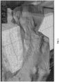
- FIG. 1 displays the initial salt model (shades of green) intersecting the 3D seismic survey (pale block) and user-selected target positions (red dots) and resulting smooth mesh (yellow) patch utilizing triangular shapes, wherein the patch is predominantly topologically consistent.
- the patch is slightly raised above the initial salt model due to the values of Z in the target positions, e.g. Z values of the missing dipping area.
- selection target positions with a Z value that same as the initial salt model will be made if no topological changes are needed.
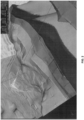
- the smoothing mesh automatically expands to connect the target points to the initial salt model, as seen in FIG. 2 , without user initiative.
- the user can alter many parameters of this connecting mesh after its initial generation. For instance, the user can control various aspects such as the extent of the mesh, the connection of the mesh to the surface of the horizon pair and the density of the mesh polygons.
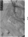
- FIG. 3 displays some of these modifications to the original mesh, in particular the location of the connection of the mesh to the surface has been modified and the surface under the mesh is enlarged. Due to the enlarged surface, the polygon density has also decreased.
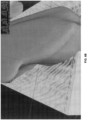
- the mesh has also been pulled (or pushed) to define a second apex (yellow web without red target points) using the push/pull tool commonly found in most modeling software.
- the modeling software displays this incorporation by e.g., a change in color of the web, as shown in FIG. 4B .
- Edits to the mesh are interactively made such that the edits can be incorporated to the mesh section by section.
- new edits can override previously incorporated edits as the user refines the mesh.
- the original salt model is updated by filling in or taking away areas between the boundary of the original salt model and the proposed mesh.
- the salt model of this sample was updated by filling in the new elevations from the proposed mesh.
- sealed horizon pairs were automatically generated and sent to the interpretative software in GeoProbe. The sealed horizon pairs can also be saved and used for further processing steps.
- the modified salt model can be used to update the velocity model and generate new migrated seismic data for comparison and additional changes to the salt model can be made until the user is satisfied with the resulting seismic imagery.
- the proposed mesh can be used to make dips, crevices, tunnels, and bridges in the salt model such that the topography of the model accurately reflect the salt structure.
- the presently described algorithm and methods can be used to alter areas inside the model.
Landscapes
- Engineering & Computer Science (AREA)
- Remote Sensing (AREA)
- Physics & Mathematics (AREA)
- Life Sciences & Earth Sciences (AREA)
- Acoustics & Sound (AREA)
- Environmental & Geological Engineering (AREA)
- Geology (AREA)
- General Life Sciences & Earth Sciences (AREA)
- General Physics & Mathematics (AREA)
- Geophysics (AREA)
- Processing Or Creating Images (AREA)
- Management, Administration, Business Operations System, And Electronic Commerce (AREA)
Claims (5)
- Computerimplementiertes Verfahren zum Modellieren eines Geokörpers in einem Reservoir, umfassend:a) Hochladen seismischer Daten aus einem Reservoir, das eine Geokörperstruktur enthält, in ein 3D-Modellierungsprogramm in einem Computer;b) Erzeugen eines Würfelanzeigemodells der Geokörperstruktur, die Horizonte in das Würfelanzeigemodellvolumen eingefügt aufweist;c) Anwenden eines Algorithmus auf das 3D-Modellierungsprogramm, der automatisch versiegelte Horizontpaare auswählt und der automatisch eine Vermaschungsdarstellung des Würfelanzeigemodells oder von Abschnitten davon glättet und verbindet;d) Auswählen eines Satzes versiegelter Horizontpaare in dem Würfelanzeigemodell mit dem Algorithmus, um ein Volumen zu definieren, das ein Geokörpermodell darstellt, das eine Grenze und interne Merkmale aufweist, und Anzeigen des Geokörpermodells auf einer Anzeige;e) Auswerten, durch einen Benutzer, der seismischen Daten und des angezeigten Geokörpermodells, um einen Bereich in dem angezeigten Geokörpermodell zu identifizieren, der verbessert werden muss;f) Markieren, durch einen Benutzer, mindestens eines vom Benutzer ausgewählten Punkts auf dem angezeigten Geokörpermodell, um das Geokörpermodell in dem Bereich anzupassen, und automatisches Erzeugen einer geglätteten Vermaschung, die den mindestens einen vom Benutzer ausgewählten Punkt schneidet;g) Erweitern der geglätteten Vermaschung, um sie mit dem Geokörpermodell zu verbinden;h) Aktualisieren des Geokörpermodells, um die geglättete Vermaschung einzugliedern, um ein aktualisiertes Geokörpermodell zu bilden;i) Erzeugen eines Satzes aktualisierter versiegelter Horizontpaare für das aktualisierte Geokörpermodell mit dem Algorithmus und Speichern des Satzes aktualisierter versiegelter Horizontpaare in einem Speicher in dem Computer;j) Wiederholen eines oder mehrerer der Schritte e-i), bis ein Benutzer feststellt, dass das aktualisierte Geokörpermodell zufriedenstellend ist, undk) Verwenden des aktualisierten Geokörpermodells beim Hervorbringen von Fluiden aus dem Reservoir; wobei der Algorithmus versiegelte Horizontpaare auswählt durch:i) Erstellen eines Stapelzählarrays, das ein mathematisches Array oder eine Matrix umfasst, die der X,Y-Größe der seismischen 3D-Daten entspricht, sodass die Anzahl der Stapelintervalle in jedem X,Y-Vermessungsraster im Modell in der entsprechenden X,Y-Zelle des Arrays aufgezeichnet wird;ii) Durchlaufen des Stapelzählarrays und Zuweisen einer einzigartigen Nummer zu jedem verbundenen Bereich, der die gleiche Anzahl von Z-Wertepaaren enthält, die einem benutzerdefinierten Anpassungskriterium entsprechen;iii) Zuweisen numerischer Patch-Identifikatoren zu jedem Z-Wertepaar;iv) Vergleichen benachbarter numerischer Patch-Identifikatoren;v) Verbinden von Patches in der Reihenfolge der Verbindungsstärke;vi) Zuweisen jedes Satzes verbundener Patches zu einem Horizontpaar; undviii) Versiegeln von Horizontpaaren durch Anwenden eines 3 × 3 digitalen Filters, der obere Horizonte auf einen Nullwert abtastet und jeden Nullwert durch einen Durchschnitt von benachbarten Nicht-Null-Höchst- und -Tiefstwerten ersetzt.
- Verfahren nach Anspruch 1, wobei eine oder mehrere Grenzen des Geokörpermodells korrigiert werden.
- Verfahren nach Anspruch 1, wobei ein internes Merkmal des Geokörpermodells korrigiert wird.
- Verfahren nach Anspruch 1, wobei Boolesche Operationen verwendet werden, um die geglättete Vermaschung in das Geokörpermodell einzugliedern, wobei das Geokörpermodell ein Salzmodell ist.
- Verfahren nach Anspruch 1, wobei die versiegelten Horizontpaare ausgewählt werden, um das Volumen zu definieren.
Applications Claiming Priority (2)
| Application Number | Priority Date | Filing Date | Title |
|---|---|---|---|
| US201562246959P | 2015-10-27 | 2015-10-27 | |
| PCT/US2016/058160 WO2017074816A1 (en) | 2015-10-27 | 2016-10-21 | Interactive salt model modification |
Publications (3)
| Publication Number | Publication Date |
|---|---|
| EP3368921A1 EP3368921A1 (de) | 2018-09-05 |
| EP3368921A4 EP3368921A4 (de) | 2019-02-27 |
| EP3368921B1 true EP3368921B1 (de) | 2023-06-21 |
Family
ID=58558444
Family Applications (1)
| Application Number | Title | Priority Date | Filing Date |
|---|---|---|---|
| EP16860551.7A Active EP3368921B1 (de) | 2015-10-27 | 2016-10-21 | Modifizierung eines interaktiven salzmodells |
Country Status (5)
| Country | Link |
|---|---|
| US (1) | US10359524B2 (de) |
| EP (1) | EP3368921B1 (de) |
| AU (1) | AU2016346919B2 (de) |
| CA (1) | CA3002775A1 (de) |
| WO (1) | WO2017074816A1 (de) |
Families Citing this family (9)
| Publication number | Priority date | Publication date | Assignee | Title |
|---|---|---|---|---|
| FR3043227A1 (de) * | 2015-11-04 | 2017-05-05 | Services Petroliers Schlumberger | |
| EP3526628B1 (de) | 2016-10-14 | 2022-03-23 | Services Pétroliers Schlumberger | Erzeugung von geologischem strukturellem modell |
| US10115231B1 (en) * | 2017-06-30 | 2018-10-30 | Dreamworks Animation Llc | Traversal selection of components for a geometric model |
| US11078786B2 (en) * | 2018-05-31 | 2021-08-03 | Saudi Arabian Oil Company | Salt mobility assessment and review technique (smart) for exploratory wells |
| RU2690089C1 (ru) * | 2018-07-24 | 2019-05-30 | Общество с ограниченной ответственностью "Газпром геологоразведка" | Способ выявления и картирования флюидонасыщенных анизотропных каверново-трещинных коллекторов в межсолевых карбонатных пластах осадочного чехла |
| US11874420B2 (en) | 2018-08-21 | 2024-01-16 | Halliburton Energy Services, Inc. | Visualizing and editing a representation of a geological surface |
| CN109696706B (zh) * | 2019-01-30 | 2020-10-09 | 中国石油天然气股份有限公司 | 盐构造检测方法、装置及存储介质 |
| CN110111413A (zh) * | 2019-04-08 | 2019-08-09 | 西安电子科技大学 | 一种基于水陆共存场景的稀疏点云三维模型建立方法 |
| US12449556B2 (en) * | 2021-03-19 | 2025-10-21 | Schlumberger Technology Corporation | Automatic salt geometry detection in a subsurface volume |
Family Cites Families (16)
| Publication number | Priority date | Publication date | Assignee | Title |
|---|---|---|---|---|
| US6313837B1 (en) | 1998-09-29 | 2001-11-06 | Schlumberger Technology Corporation | Modeling at more than one level of resolution |
| US6829570B1 (en) * | 1999-11-18 | 2004-12-07 | Schlumberger Technology Corporation | Oilfield analysis systems and methods |
| NL1024444C2 (nl) | 2003-10-03 | 2005-04-08 | J O A Beheer B V | Werkwijze, inrichting, computerprogramma en gegevensdrager voor het met een digitale verwerkingseenheid modelleren van een meerdimensionale heterogene structuur. |
| US7283911B2 (en) * | 2004-10-22 | 2007-10-16 | Landmark Graphics Corporation | System and method for interpreting reverse faults and multiple z-valued seismic horizons |
| US20070182762A1 (en) | 2006-02-03 | 2007-08-09 | Xiaqing Wu | Real-time interactive rubber sheeting using dynamic delaunay triangulation |
| GB0722469D0 (en) | 2007-11-16 | 2007-12-27 | Statoil Asa | Forming a geological model |
| WO2009142872A1 (en) * | 2008-05-22 | 2009-11-26 | Exxonmobil Upstream Research Company | Seismic horizon skeletonization |
| US8743115B1 (en) | 2009-10-23 | 2014-06-03 | Paradigm Sciences Ltd. | Systems and methods for coordinated editing of seismic data in dual model |
| US9229129B2 (en) | 2010-12-10 | 2016-01-05 | Conocophillips Company | Reservoir geobody calculation |
| US9625595B2 (en) | 2012-03-06 | 2017-04-18 | Schlumberger Technology Corporation | Interpretation and feature detection in a seismic volume using bump mapping and lighting |
| WO2014074213A2 (en) * | 2012-11-07 | 2014-05-15 | Exxonmobil Upstream Research Company | Method for knowledge capture and pattern recognition for the detection of hydrocarbon accumulations |
| US20140214328A1 (en) * | 2013-01-28 | 2014-07-31 | Westerngeco L.L.C. | Salt body extraction |
| US20140222403A1 (en) * | 2013-02-07 | 2014-08-07 | Schlumberger Technology Corporation | Geologic model via implicit function |
| BR112015028562A2 (pt) | 2013-05-15 | 2017-07-25 | Logined Bv | método, sistema, e um ou mais meios de armazenamento legíveis por computador |
| US9835747B2 (en) | 2013-05-30 | 2017-12-05 | Exxonmobil Upstream Research Company | Automated interpretation error correction |
| CA2907871C (en) * | 2014-10-09 | 2024-02-20 | Schlumberger Canada Limited | Fault representation |
-
2016
- 2016-10-21 AU AU2016346919A patent/AU2016346919B2/en active Active
- 2016-10-21 CA CA3002775A patent/CA3002775A1/en active Pending
- 2016-10-21 WO PCT/US2016/058160 patent/WO2017074816A1/en not_active Ceased
- 2016-10-21 EP EP16860551.7A patent/EP3368921B1/de active Active
- 2016-10-21 US US15/299,949 patent/US10359524B2/en active Active
Also Published As
| Publication number | Publication date |
|---|---|
| US20170115412A1 (en) | 2017-04-27 |
| EP3368921A4 (de) | 2019-02-27 |
| AU2016346919B2 (en) | 2022-02-17 |
| EP3368921A1 (de) | 2018-09-05 |
| US10359524B2 (en) | 2019-07-23 |
| AU2016346919A1 (en) | 2018-05-17 |
| WO2017074816A1 (en) | 2017-05-04 |
| CA3002775A1 (en) | 2017-05-04 |
Similar Documents
| Publication | Publication Date | Title |
|---|---|---|
| US10359524B2 (en) | Interactive salt model modification | |
| US10838108B2 (en) | Method and system for interpolating discontinuous functions in a subsurface model | |
| EP3956541B1 (de) | Modellierung und simulation von verwerfungen in unterirdischen formationen | |
| US10571601B2 (en) | Geologic fault representation for flow simulation | |
| US11506807B2 (en) | Methods and systems for simulation gridding with partial faults | |
| US9022129B2 (en) | Tracking geologic object and detecting geologic anomalies in exploration seismic data volume | |
| EP3293552B1 (de) | System und verfahren zum editieren von geologischen modellen durch wechseln zwischen volumenbasierten modellen und oberflächenbasierten strukturmodellen mit stratigrafischen faserbündeln | |
| US20140222403A1 (en) | Geologic model via implicit function | |
| US20150113379A1 (en) | Representation of unstructured grids | |
| NO20171868A1 (en) | Geologic stratigraphy via implicit and jump functions | |
| WO2017016895A1 (en) | Assignment of systems tracts | |
| US10387583B2 (en) | Rotations from gradient directions | |
| US20140222345A1 (en) | Methods and systems of incorporating pseudo-surface pick locations in seismic velocity models | |
| EP3785233B1 (de) | Fehlerstrahlungsbasierte gitterunterteilung | |
| CN115166854A (zh) | 时间域高频层序地层体构建方法、装置、电子设备及介质 | |
| US20240111067A1 (en) | Faulted seismic horizon mapping | |
| EP4264554B1 (de) | System und verfahren zum prädiktiven geologischen zeichnen | |
| CN113655525A (zh) | 基于高速砾岩的构造高点偏移的校正方法及装置 | |
| US20250314789A1 (en) | Internal imaging and model construction | |
| Perdomo et al. | Quantifying prospectivity and reducing drilling risk with seismic uncertainty analyses: A Gulf of Mexico case history | |
| WO2024206578A1 (en) | Subsurface discontinuity modeling framework |
Legal Events
| Date | Code | Title | Description |
|---|---|---|---|
| STAA | Information on the status of an ep patent application or granted ep patent |
Free format text: STATUS: THE INTERNATIONAL PUBLICATION HAS BEEN MADE |
|
| PUAI | Public reference made under article 153(3) epc to a published international application that has entered the european phase |
Free format text: ORIGINAL CODE: 0009012 |
|
| STAA | Information on the status of an ep patent application or granted ep patent |
Free format text: STATUS: REQUEST FOR EXAMINATION WAS MADE |
|
| 17P | Request for examination filed |
Effective date: 20180430 |
|
| AK | Designated contracting states |
Kind code of ref document: A1 Designated state(s): AL AT BE BG CH CY CZ DE DK EE ES FI FR GB GR HR HU IE IS IT LI LT LU LV MC MK MT NL NO PL PT RO RS SE SI SK SM TR |
|
| AX | Request for extension of the european patent |
Extension state: BA ME |
|
| DAV | Request for validation of the european patent (deleted) | ||
| DAX | Request for extension of the european patent (deleted) | ||
| A4 | Supplementary search report drawn up and despatched |
Effective date: 20190130 |
|
| RIC1 | Information provided on ipc code assigned before grant |
Ipc: G06T 17/00 20060101ALI20190124BHEP Ipc: G06T 15/00 20110101ALI20190124BHEP Ipc: G01V 11/00 20060101ALI20190124BHEP Ipc: G01V 1/34 20060101AFI20190124BHEP |
|
| STAA | Information on the status of an ep patent application or granted ep patent |
Free format text: STATUS: EXAMINATION IS IN PROGRESS |
|
| 17Q | First examination report despatched |
Effective date: 20190307 |
|
| RAP1 | Party data changed (applicant data changed or rights of an application transferred) |
Owner name: CONOCOPHILLIPS COMPANY |
|
| RAP1 | Party data changed (applicant data changed or rights of an application transferred) |
Owner name: CONOCOPHILLIPS COMPANY |
|
| GRAP | Despatch of communication of intention to grant a patent |
Free format text: ORIGINAL CODE: EPIDOSNIGR1 |
|
| STAA | Information on the status of an ep patent application or granted ep patent |
Free format text: STATUS: GRANT OF PATENT IS INTENDED |
|
| INTG | Intention to grant announced |
Effective date: 20230403 |
|
| GRAS | Grant fee paid |
Free format text: ORIGINAL CODE: EPIDOSNIGR3 |
|
| GRAA | (expected) grant |
Free format text: ORIGINAL CODE: 0009210 |
|
| STAA | Information on the status of an ep patent application or granted ep patent |
Free format text: STATUS: THE PATENT HAS BEEN GRANTED |
|
| AK | Designated contracting states |
Kind code of ref document: B1 Designated state(s): AL AT BE BG CH CY CZ DE DK EE ES FI FR GB GR HR HU IE IS IT LI LT LU LV MC MK MT NL NO PL PT RO RS SE SI SK SM TR |
|
| REG | Reference to a national code |
Ref country code: CH Ref legal event code: EP |
|
| REG | Reference to a national code |
Ref country code: DE Ref legal event code: R096 Ref document number: 602016080520 Country of ref document: DE |
|
| REG | Reference to a national code |
Ref country code: AT Ref legal event code: REF Ref document number: 1581291 Country of ref document: AT Kind code of ref document: T Effective date: 20230715 |
|
| REG | Reference to a national code |
Ref country code: IE Ref legal event code: FG4D |
|
| REG | Reference to a national code |
Ref country code: NO Ref legal event code: T2 Effective date: 20230621 |
|
| REG | Reference to a national code |
Ref country code: LT Ref legal event code: MG9D |
|
| REG | Reference to a national code |
Ref country code: NL Ref legal event code: MP Effective date: 20230621 |
|
| PG25 | Lapsed in a contracting state [announced via postgrant information from national office to epo] |
Ref country code: SE Free format text: LAPSE BECAUSE OF FAILURE TO SUBMIT A TRANSLATION OF THE DESCRIPTION OR TO PAY THE FEE WITHIN THE PRESCRIBED TIME-LIMIT Effective date: 20230621 |
|
| REG | Reference to a national code |
Ref country code: AT Ref legal event code: MK05 Ref document number: 1581291 Country of ref document: AT Kind code of ref document: T Effective date: 20230621 |
|
| PG25 | Lapsed in a contracting state [announced via postgrant information from national office to epo] |
Ref country code: RS Free format text: LAPSE BECAUSE OF FAILURE TO SUBMIT A TRANSLATION OF THE DESCRIPTION OR TO PAY THE FEE WITHIN THE PRESCRIBED TIME-LIMIT Effective date: 20230621 Ref country code: NL Free format text: LAPSE BECAUSE OF FAILURE TO SUBMIT A TRANSLATION OF THE DESCRIPTION OR TO PAY THE FEE WITHIN THE PRESCRIBED TIME-LIMIT Effective date: 20230621 Ref country code: LV Free format text: LAPSE BECAUSE OF FAILURE TO SUBMIT A TRANSLATION OF THE DESCRIPTION OR TO PAY THE FEE WITHIN THE PRESCRIBED TIME-LIMIT Effective date: 20230621 Ref country code: LT Free format text: LAPSE BECAUSE OF FAILURE TO SUBMIT A TRANSLATION OF THE DESCRIPTION OR TO PAY THE FEE WITHIN THE PRESCRIBED TIME-LIMIT Effective date: 20230621 Ref country code: HR Free format text: LAPSE BECAUSE OF FAILURE TO SUBMIT A TRANSLATION OF THE DESCRIPTION OR TO PAY THE FEE WITHIN THE PRESCRIBED TIME-LIMIT Effective date: 20230621 Ref country code: GR Free format text: LAPSE BECAUSE OF FAILURE TO SUBMIT A TRANSLATION OF THE DESCRIPTION OR TO PAY THE FEE WITHIN THE PRESCRIBED TIME-LIMIT Effective date: 20230922 |
|
| PG25 | Lapsed in a contracting state [announced via postgrant information from national office to epo] |
Ref country code: FI Free format text: LAPSE BECAUSE OF FAILURE TO SUBMIT A TRANSLATION OF THE DESCRIPTION OR TO PAY THE FEE WITHIN THE PRESCRIBED TIME-LIMIT Effective date: 20230621 |
|
| PG25 | Lapsed in a contracting state [announced via postgrant information from national office to epo] |
Ref country code: SK Free format text: LAPSE BECAUSE OF FAILURE TO SUBMIT A TRANSLATION OF THE DESCRIPTION OR TO PAY THE FEE WITHIN THE PRESCRIBED TIME-LIMIT Effective date: 20230621 |
|
| P01 | Opt-out of the competence of the unified patent court (upc) registered |
Effective date: 20231207 |
|
| PG25 | Lapsed in a contracting state [announced via postgrant information from national office to epo] |
Ref country code: ES Free format text: LAPSE BECAUSE OF FAILURE TO SUBMIT A TRANSLATION OF THE DESCRIPTION OR TO PAY THE FEE WITHIN THE PRESCRIBED TIME-LIMIT Effective date: 20230621 |
|
| PG25 | Lapsed in a contracting state [announced via postgrant information from national office to epo] |
Ref country code: IS Free format text: LAPSE BECAUSE OF FAILURE TO SUBMIT A TRANSLATION OF THE DESCRIPTION OR TO PAY THE FEE WITHIN THE PRESCRIBED TIME-LIMIT Effective date: 20231021 |
|
| PG25 | Lapsed in a contracting state [announced via postgrant information from national office to epo] |
Ref country code: SM Free format text: LAPSE BECAUSE OF FAILURE TO SUBMIT A TRANSLATION OF THE DESCRIPTION OR TO PAY THE FEE WITHIN THE PRESCRIBED TIME-LIMIT Effective date: 20230621 Ref country code: SK Free format text: LAPSE BECAUSE OF FAILURE TO SUBMIT A TRANSLATION OF THE DESCRIPTION OR TO PAY THE FEE WITHIN THE PRESCRIBED TIME-LIMIT Effective date: 20230621 Ref country code: RO Free format text: LAPSE BECAUSE OF FAILURE TO SUBMIT A TRANSLATION OF THE DESCRIPTION OR TO PAY THE FEE WITHIN THE PRESCRIBED TIME-LIMIT Effective date: 20230621 Ref country code: PT Free format text: LAPSE BECAUSE OF FAILURE TO SUBMIT A TRANSLATION OF THE DESCRIPTION OR TO PAY THE FEE WITHIN THE PRESCRIBED TIME-LIMIT Effective date: 20231023 Ref country code: IS Free format text: LAPSE BECAUSE OF FAILURE TO SUBMIT A TRANSLATION OF THE DESCRIPTION OR TO PAY THE FEE WITHIN THE PRESCRIBED TIME-LIMIT Effective date: 20231021 Ref country code: ES Free format text: LAPSE BECAUSE OF FAILURE TO SUBMIT A TRANSLATION OF THE DESCRIPTION OR TO PAY THE FEE WITHIN THE PRESCRIBED TIME-LIMIT Effective date: 20230621 Ref country code: EE Free format text: LAPSE BECAUSE OF FAILURE TO SUBMIT A TRANSLATION OF THE DESCRIPTION OR TO PAY THE FEE WITHIN THE PRESCRIBED TIME-LIMIT Effective date: 20230621 Ref country code: CZ Free format text: LAPSE BECAUSE OF FAILURE TO SUBMIT A TRANSLATION OF THE DESCRIPTION OR TO PAY THE FEE WITHIN THE PRESCRIBED TIME-LIMIT Effective date: 20230621 Ref country code: AT Free format text: LAPSE BECAUSE OF FAILURE TO SUBMIT A TRANSLATION OF THE DESCRIPTION OR TO PAY THE FEE WITHIN THE PRESCRIBED TIME-LIMIT Effective date: 20230621 |
|
| PG25 | Lapsed in a contracting state [announced via postgrant information from national office to epo] |
Ref country code: PL Free format text: LAPSE BECAUSE OF FAILURE TO SUBMIT A TRANSLATION OF THE DESCRIPTION OR TO PAY THE FEE WITHIN THE PRESCRIBED TIME-LIMIT Effective date: 20230621 |
|
| REG | Reference to a national code |
Ref country code: DE Ref legal event code: R097 Ref document number: 602016080520 Country of ref document: DE |
|
| PLBE | No opposition filed within time limit |
Free format text: ORIGINAL CODE: 0009261 |
|
| STAA | Information on the status of an ep patent application or granted ep patent |
Free format text: STATUS: NO OPPOSITION FILED WITHIN TIME LIMIT |
|
| PG25 | Lapsed in a contracting state [announced via postgrant information from national office to epo] |
Ref country code: DK Free format text: LAPSE BECAUSE OF FAILURE TO SUBMIT A TRANSLATION OF THE DESCRIPTION OR TO PAY THE FEE WITHIN THE PRESCRIBED TIME-LIMIT Effective date: 20230621 |
|
| REG | Reference to a national code |
Ref country code: DE Ref legal event code: R119 Ref document number: 602016080520 Country of ref document: DE |
|
| PG25 | Lapsed in a contracting state [announced via postgrant information from national office to epo] |
Ref country code: SI Free format text: LAPSE BECAUSE OF FAILURE TO SUBMIT A TRANSLATION OF THE DESCRIPTION OR TO PAY THE FEE WITHIN THE PRESCRIBED TIME-LIMIT Effective date: 20230621 |
|
| 26N | No opposition filed |
Effective date: 20240322 |
|
| PG25 | Lapsed in a contracting state [announced via postgrant information from national office to epo] |
Ref country code: SI Free format text: LAPSE BECAUSE OF FAILURE TO SUBMIT A TRANSLATION OF THE DESCRIPTION OR TO PAY THE FEE WITHIN THE PRESCRIBED TIME-LIMIT Effective date: 20230621 Ref country code: IT Free format text: LAPSE BECAUSE OF FAILURE TO SUBMIT A TRANSLATION OF THE DESCRIPTION OR TO PAY THE FEE WITHIN THE PRESCRIBED TIME-LIMIT Effective date: 20230621 Ref country code: MC Free format text: LAPSE BECAUSE OF FAILURE TO SUBMIT A TRANSLATION OF THE DESCRIPTION OR TO PAY THE FEE WITHIN THE PRESCRIBED TIME-LIMIT Effective date: 20230621 |
|
| REG | Reference to a national code |
Ref country code: CH Ref legal event code: PL |
|
| REG | Reference to a national code |
Ref country code: BE Ref legal event code: MM Effective date: 20231031 |
|
| PG25 | Lapsed in a contracting state [announced via postgrant information from national office to epo] |
Ref country code: LU Free format text: LAPSE BECAUSE OF NON-PAYMENT OF DUE FEES Effective date: 20231021 |
|
| PG25 | Lapsed in a contracting state [announced via postgrant information from national office to epo] |
Ref country code: LU Free format text: LAPSE BECAUSE OF NON-PAYMENT OF DUE FEES Effective date: 20231021 |
|
| PG25 | Lapsed in a contracting state [announced via postgrant information from national office to epo] |
Ref country code: CH Free format text: LAPSE BECAUSE OF NON-PAYMENT OF DUE FEES Effective date: 20231031 |
|
| PG25 | Lapsed in a contracting state [announced via postgrant information from national office to epo] |
Ref country code: FR Free format text: LAPSE BECAUSE OF NON-PAYMENT OF DUE FEES Effective date: 20231031 Ref country code: DE Free format text: LAPSE BECAUSE OF NON-PAYMENT OF DUE FEES Effective date: 20240501 Ref country code: CH Free format text: LAPSE BECAUSE OF NON-PAYMENT OF DUE FEES Effective date: 20231031 |
|
| PG25 | Lapsed in a contracting state [announced via postgrant information from national office to epo] |
Ref country code: BE Free format text: LAPSE BECAUSE OF NON-PAYMENT OF DUE FEES Effective date: 20231031 |
|
| PG25 | Lapsed in a contracting state [announced via postgrant information from national office to epo] |
Ref country code: IE Free format text: LAPSE BECAUSE OF NON-PAYMENT OF DUE FEES Effective date: 20231021 |
|
| PG25 | Lapsed in a contracting state [announced via postgrant information from national office to epo] |
Ref country code: IE Free format text: LAPSE BECAUSE OF NON-PAYMENT OF DUE FEES Effective date: 20231021 |
|
| PG25 | Lapsed in a contracting state [announced via postgrant information from national office to epo] |
Ref country code: BG Free format text: LAPSE BECAUSE OF FAILURE TO SUBMIT A TRANSLATION OF THE DESCRIPTION OR TO PAY THE FEE WITHIN THE PRESCRIBED TIME-LIMIT Effective date: 20230621 |
|
| PG25 | Lapsed in a contracting state [announced via postgrant information from national office to epo] |
Ref country code: BG Free format text: LAPSE BECAUSE OF FAILURE TO SUBMIT A TRANSLATION OF THE DESCRIPTION OR TO PAY THE FEE WITHIN THE PRESCRIBED TIME-LIMIT Effective date: 20230621 |
|
| PG25 | Lapsed in a contracting state [announced via postgrant information from national office to epo] |
Ref country code: CY Free format text: LAPSE BECAUSE OF FAILURE TO SUBMIT A TRANSLATION OF THE DESCRIPTION OR TO PAY THE FEE WITHIN THE PRESCRIBED TIME-LIMIT; INVALID AB INITIO Effective date: 20161021 |
|
| PG25 | Lapsed in a contracting state [announced via postgrant information from national office to epo] |
Ref country code: HU Free format text: LAPSE BECAUSE OF FAILURE TO SUBMIT A TRANSLATION OF THE DESCRIPTION OR TO PAY THE FEE WITHIN THE PRESCRIBED TIME-LIMIT; INVALID AB INITIO Effective date: 20161021 |
|
| PGFP | Annual fee paid to national office [announced via postgrant information from national office to epo] |
Ref country code: NO Payment date: 20250925 Year of fee payment: 10 |
|
| PGFP | Annual fee paid to national office [announced via postgrant information from national office to epo] |
Ref country code: GB Payment date: 20250923 Year of fee payment: 10 |
|
| PG25 | Lapsed in a contracting state [announced via postgrant information from national office to epo] |
Ref country code: TR Free format text: LAPSE BECAUSE OF FAILURE TO SUBMIT A TRANSLATION OF THE DESCRIPTION OR TO PAY THE FEE WITHIN THE PRESCRIBED TIME-LIMIT Effective date: 20230621 |