EP3369273B1 - Réglage de puissance d'une tête radio d'un système radio d'intérieur - Google Patents
Réglage de puissance d'une tête radio d'un système radio d'intérieur Download PDFInfo
- Publication number
- EP3369273B1 EP3369273B1 EP15907397.2A EP15907397A EP3369273B1 EP 3369273 B1 EP3369273 B1 EP 3369273B1 EP 15907397 A EP15907397 A EP 15907397A EP 3369273 B1 EP3369273 B1 EP 3369273B1
- Authority
- EP
- European Patent Office
- Prior art keywords
- wall
- signal strength
- radio head
- radio
- indoor
- Prior art date
- Legal status (The legal status is an assumption and is not a legal conclusion. Google has not performed a legal analysis and makes no representation as to the accuracy of the status listed.)
- Active
Links
Images




Classifications
-
- H—ELECTRICITY
- H04—ELECTRIC COMMUNICATION TECHNIQUE
- H04W—WIRELESS COMMUNICATION NETWORKS
- H04W52/00—Power management, e.g. Transmission Power Control [TPC] or power classes
- H04W52/04—Transmission power control [TPC]
- H04W52/06—TPC algorithms
- H04W52/14—Separate analysis of uplink or downlink
-
- H—ELECTRICITY
- H04—ELECTRIC COMMUNICATION TECHNIQUE
- H04W—WIRELESS COMMUNICATION NETWORKS
- H04W24/00—Supervisory, monitoring or testing arrangements
- H04W24/02—Arrangements for optimising operational condition
-
- H—ELECTRICITY
- H04—ELECTRIC COMMUNICATION TECHNIQUE
- H04W—WIRELESS COMMUNICATION NETWORKS
- H04W52/00—Power management, e.g. Transmission Power Control [TPC] or power classes
- H04W52/04—Transmission power control [TPC]
- H04W52/18—TPC being performed according to specific parameters
- H04W52/24—TPC being performed according to specific parameters using SIR [Signal to Interference Ratio] or other wireless path parameters
- H04W52/242—TPC being performed according to specific parameters using SIR [Signal to Interference Ratio] or other wireless path parameters taking into account path loss
-
- H—ELECTRICITY
- H04—ELECTRIC COMMUNICATION TECHNIQUE
- H04W—WIRELESS COMMUNICATION NETWORKS
- H04W52/00—Power management, e.g. Transmission Power Control [TPC] or power classes
- H04W52/04—Transmission power control [TPC]
- H04W52/18—TPC being performed according to specific parameters
- H04W52/24—TPC being performed according to specific parameters using SIR [Signal to Interference Ratio] or other wireless path parameters
- H04W52/245—TPC being performed according to specific parameters using SIR [Signal to Interference Ratio] or other wireless path parameters taking into account received signal strength
-
- H—ELECTRICITY
- H04—ELECTRIC COMMUNICATION TECHNIQUE
- H04W—WIRELESS COMMUNICATION NETWORKS
- H04W52/00—Power management, e.g. Transmission Power Control [TPC] or power classes
- H04W52/04—Transmission power control [TPC]
- H04W52/18—TPC being performed according to specific parameters
- H04W52/28—TPC being performed according to specific parameters using user profile, e.g. mobile speed, priority or network state, e.g. standby, idle or non-transmission
- H04W52/283—Power depending on the position of the mobile
-
- H—ELECTRICITY
- H04—ELECTRIC COMMUNICATION TECHNIQUE
- H04W—WIRELESS COMMUNICATION NETWORKS
- H04W52/00—Power management, e.g. Transmission Power Control [TPC] or power classes
- H04W52/04—Transmission power control [TPC]
- H04W52/06—TPC algorithms
- H04W52/14—Separate analysis of uplink or downlink
- H04W52/143—Downlink power control
-
- H—ELECTRICITY
- H04—ELECTRIC COMMUNICATION TECHNIQUE
- H04W—WIRELESS COMMUNICATION NETWORKS
- H04W52/00—Power management, e.g. Transmission Power Control [TPC] or power classes
- H04W52/04—Transmission power control [TPC]
- H04W52/06—TPC algorithms
- H04W52/14—Separate analysis of uplink or downlink
- H04W52/146—Uplink power control
Definitions
- the proposed technology generally relates to wireless communications technology, and more specifically to a method for enabling power adjustment of a radio head of an indoor radio system, a device configured to enable power adjustment of a radio head of an indoor radio system, a corresponding network device, indoor radio system, computer program and computer program product as well as an apparatus for enabling power adjustment of a radio head of an indoor radio system.
- FIG. 1 is a schematic diagram illustrating an example of a wireless communication context including an outdoor domain and an indoor domain in which wireless communication devices 30 are located.
- An indoor radio system 10 is responsible for serving wireless communication devices 30 in the indoor domain using one or more radio heads 15.
- a base station 20 is configured to provide one or more macro cells for serving wireless communication devices 30 in the outdoor domain, and possibly also in the indoor domain.
- the indoor radio head coverage may also extend to the outdoor domain, which will be discussed later on.
- IBS In-Building Systems
- the antenna points include means for amplifying the signal, and in some cases also for translating the signal to a different frequency. This frequency can be both lower and higher than the original frequency.
- the signal is transformed into an optical signal that is transmitted over low loss optical fibers to a central point where the signal is converted back to Radio Frequency, RF, and subsequently digitalized and downconverted to baseband.
- RF signals from multiple antenna points are, typically passively, combined at the central point.
- the RDS system is in one perspective a complete radio base station with split architecture, but can also be seen as one type of active DAS, with integrated antenna(s) in the remote unit.
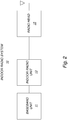
- FIG. 2 is a schematic diagram illustrating a non-limiting example of an indoor radio system.
- the indoor radio system 10 comprises a Base Band Unit, BBU, 11 and Indoor Radio Unit, IRU, 13, and one or more radio heads 15 having one or more associated antennas.
- the radio head 15 or dot is the remote unit with integrated antenna.
- the IRU is the head end interfacing the radio head or dot over CAT cable.
- the IRU may be connected to the BBU, through a CPRI interface.
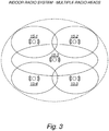
- FIG. 3 is a schematic diagram illustrating an example of the coverage area of an indoor radio system having multiple radio heads.
- the overall radio coverage of an indoor radio system is built up from the radio head coverage of multiple radio heads 15-1 to 15-5.
- an indoor radio system such as an RDS
- the most common goal is to cover all users located inside the building, and no users outside of the building. This can be achieved through a combination of thorough pre-planning of system deployment followed by reconfiguration of system parameters based on measurements/tests in and around the building after the installation is completed.
- Such planning and, especially, testing and tuning is however time consuming and costly, and most of the time beyond the budget for such an installation.
- a normal installation consists of a rough dimensioning followed by a quick verification of the performance inside the building.
- the system is often over-dimensioned in terms of output power and node density, leading to a coverage area including also the outdoor surroundings of the building.
- Radio coverage outside the building can sometimes result in unwanted behavior and negative consequences.
- cars passing by may handover to the RDS system and then back to the macro network. Handover can have impact on user quality experience and even lead to dropped calls.
- positioning of emergency calls may faulty indicate the call being inside the building instead of outside the building.
- Reference [1] relates to setting a transmit power of a femto cell depending on received power of at least one neighboring macro cell.
- US Published Patent Application No. 2013/0237227 A1 describes a system and a method for classifying an indoor location of a femtocell, and allocating or adjusting femtocell radio frequency resources and parameters of the femtocell based on the indoor location classification, in order to optimize coverage by the femtocell and reduce interference with neighbouring macro and femtocells.
- Jinyeol Roh et al. document title "Adaptive In-building Propagation Simulator using ray tracing in WCDMA networks," published on 19th November 2008 in IEEE region 10 conference, Piscataway, NJ, USA , describes an Adaptive In-building Propagation Simulator (AIPS) that predicts in-building wireless service coverage and the received signal strength of a mobile station by designing the location of repeater, wall, and antenna using an adaptive propagation model.
- AIPS Adaptive In-building Propagation Simulator
- a method for enabling power adjustment of a radio head of an indoor radio system comprises identifying, based on signal strength measurements in relation to wireless communication devices connected to the radio head, presence of a wall of a building in which the indoor radio system is located. The method also comprises triggering an adjustment of transmit power of the radio head to align the radio head coverage with the wall.
- a device configured to enable power adjustment of a radio head of an indoor radio system, wherein said device is configured to identify, based on signal strength measurements in relation to wireless communication devices connected to the radio head, presence of a wall of a building in which the indoor radio system is located; and wherein said device is configured to trigger an adjustment of transmit power of the radio head to align the radio head coverage with the wall.
- a network device comprising a device of the second aspect.
- an indoor radio system comprising a device of the second aspect.
- a computer program comprising instructions, which when executed by at least one processor cause the at least one processor to:
- a computer-program product comprising a computer-readable medium having stored thereon a computer program of the fifth aspect.
- an apparatus for enabling power adjustment of a radio head of an indoor radio system comprises an identification module for identifying, based on signal strength measurements in relation to wireless communication devices connected to the radio head, presence of a wall of a building in which the indoor radio system is located.
- the apparatus also comprises a trigger module for triggering an adjustment of transmit power of the radio head to align the radio head coverage with the wall.
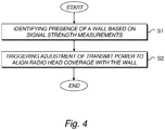
- FIG. 4 is a schematic flow diagram illustrating an example of a method for enabling power adjustment of a radio head of an indoor radio system according to an embodiment.
- the method comprises:
- Reference [1] sets power related to macro signal strength rather than the building structure and outer walls. The cell edge will not target the wall and the indoor cell will not cover the building specifically.
- the identifying and triggering may be performed per radio head.
- the adjustment of transmit power is triggered to provide indoor coverage but not outdoor coverage. This means that the unwanted behavior and negative consequences of radio coverage outside the building can be eliminated or at least alleviated.
- the signal strength measurements include uplink signal strength measurements and/or downlink signal strength measurements or path loss measurements, related to the radio head.
- the uplink signal strength of transmissions from wireless communication devices connected to the radio head may be measured in the radio head and used, or the downlink signal strength of transmissions from the radio head experienced by the wireless communication devices may be measured and reported for use in identifying the presence of the wall.
- Path loss can be a used measure if transmission power is known, such as for example used and defined in 3GPP for LTE UEs.
- FIG. 5A is a schematic diagram illustrating an example of an initial coverage area of a radio head 15 of an indoor radio system extending to the outdoor domain and a subsequent power adjustment to align the radio head coverage with the wall.
- FIG. 5B is a schematic diagram illustrating an example of a curve diagram relating received signal strength to the distance from the radio head, corresponding to the example of FIG. 5A .
- the wall loss i.e. the signal attenuation caused by the wall, is seen as the signal strength drop at distance 25 (m).
- a statistical distribution is created based on the signal strength measurements, and a location of the wall is identified in the statistical distribution.
- the wall may be identified from less frequent levels of signal strength in the statistical distribution.
- the adjustment of transmit power may be determined based on the location of the wall in the statistical distribution.
- FIG. 6A is a schematic diagram illustrating an example of a signal strength histogram.
- the wall is located within the radio head coverage, and the location of the wall can be identified in the statistical distribution, e.g. as a drop or valley in the middle of the histogram. More specifically the location of the wall can be identified from the less frequent levels of signal strength, disregarding the edges of the distribution.
- the histogram illustrates the situation of an unoptimized coverage, where the indoor coverage actually extends into the outdoor domain. A power adjustment to align the radio head coverage with the wall is thus desirable to provide for a more optimized coverage.
- FIG. 6B is a schematic diagram illustrating an example of Cumulative Distribution Function, CDF, curves for unoptimized coverage and optimized coverage, respectively, wherein the curve related to unoptimized coverage corresponds to the signal strength histogram of FIG. 6A .
- CDF Cumulative Distribution Function
- the wall can be identified as a knee or thigh in the curve related to unoptimized coverage.
- Discriminant Function Classification may be used to identify the location of the wall, e.g. by using a discriminator function such as the Fischer function to find a dividing point or border between two sets or groups of signal strength values within the distribution.
- a discriminator function such as the Fischer function
- the wall may be identified also based on signal strength measurements related to at least one other cell.
- the wall may be identified based on a geometry measure defined as a relation between signal strength related to the radio head and signal strength of at least one other cell.
- the wall may be identified based on a geometry measure defined as i) signal strength related to the radio head divided by signal strength of the strongest outdoor cell, or ii) signal strength related to the radio head divided by the sum of all other signal strengths.
- geometry In linear scale, geometry is considered as a ratio, whereas in logarithmic scale (dB), geometry is normally defined as a difference. Both ways of considering geometry are equivalent.
- the signal strength related to the radio head and the signal strength related to the other cell or cells may be used individually, without forming a geometry measure. For example, by applying a discriminator function such as the Fischer function for each dimension, treating signal strength related to the radio head and signal strength related to the other cell(s) individually.
- a discriminator function such as the Fischer function for each dimension
- the adjustment of transmit power may be determined to locate an edge of the radio head coverage on either side of the wall, or within the wall.
- the wall is an outer wall of the building, although it is in principle also possible to consider a thicker inner wall of the building or other obstacles, building structures or similar structures attenuating the radio signal and desired to be used as a border (wall) between (indoor and outdoor) cells.
- the proposed solution targets to adjust the output power of each radio head/access point/dot/antenna point so that the cell border between the indoor system and the outdoor network is located in the outer wall of the building or in the vicinity of the wall.
- the method may be performed in the BBU, IRU or in each concerned radio head/access point/dot/antenna point.
- a power adjustment command is sent from the BBU to the radio head/access point/dot/antenna point. If the method is performed in the radio head/access point/dot/antenna point, measurements/reports received in the BBU may have to be signaled to the radio head/access point/dot/antenna point.
- the method may also be performed in a network device, which may be located outside of the radio access network, e.g. in the core network, an OSS system or a cloud-based network environment.
- a network device which may be located outside of the radio access network, e.g. in the core network, an OSS system or a cloud-based network environment.
- the procedure starts at maximum output power.
- signal strength measurements related to the radio head/access point/dot/antenna point are obtained. For example, these may be achieved through reported downlink signal strengths from the connected UEs, or by uplink signal strength measurements at the radio head/access point/dot/antenna point.
- UE reports that may be used for this purpose are for example RSRP reports for LTE, RSCP for WCDMA and RxLev for GSM.
- the received UL signal strength may for example be measured directly on certain channels.
- the transmit power level may need to be compensated.
- LTE with fractional power control is well suited, where a knee in the received signal strength distribution will remain even without compensating for the transmit power.
- FIG. 7 is a schematic curve diagram illustrating a simplified example of a signal strength distribution. If the outer wall is within the coverage area a sharp drop (a knee/thigh) will be present in the distribution, see FIG. 7 . Assume, for example, that the outer wall attenuation is 25dB, and that indoor users close to the outer wall has a received signal strength of -55dBm. There will then exist no users with a signal strength between -55 and -80dBm, and the users with signal strength below -80dBm will be outside the building.
- a sharp drop a knee/thigh
- an embodiment of the proposed solution collects a number of signal strength values, creates a statistical distribution, detects presence of a wall and, in the case of detection, adjusts an emitted signal power based on the estimated location and thickness (in RF domain) of the wall.
- a geometry measure can be used.
- the geometry measure can be calculated as the signal strength of the radio head/access point/dot/antenna point minus the linear sum of all the other signal strengths, alternatively only minus the signal strength of the strongest outdoor (macro) cell.
- the statistical distribution search for the wall loss knee/thigh in step 3 can be made more or less advanced, e.g. using Discriminant Function Classification.
- the signal strength at either side i.e. just inside and just outside of the wall may be stored as S_inside and S_outside, respectively.
- wireless communication device may refer to User Equipment (UE), a mobile station, a mobile terminal, a mobile phone, a cellular phone, a Personal Digital Assistant (PDA), equipped with radio communication capabilities, a smart phone, a laptop or Personal Computer (PC), equipped with an internal or external mobile broadband modem, a tablet with radio communication capabilities, a target device, a device to device UE, a machine type UE or UE capable of machine to machine communication, Customer Premises Equipment (CPE), Laptop Embedded Equipment (LEE), Laptop Mounted Equipment (LME), USB dongle, a portable electronic radio communication device, a sensor device equipped with radio communication capabilities or the like.
- CPE Customer Premises Equipment
- LEE Laptop Embedded Equipment
- LME Laptop Mounted Equipment
- USB dongle a portable electronic radio communication device, a sensor device equipped with radio communication capabilities or the like.
- wireless communication device should be interpreted as a non-limiting term comprising any type of wireless device communicating with a network node in a wireless communication system and/or possibly communicating directly with another wireless communication device.
- a wireless communication device may be any device equipped with circuitry for wireless communication according to any relevant standard for communication.
- the non-limiting term "indoor radio system” may refer to any radio access system adapted or suitable for an indoor environment, including but not limited to DAS, active DAS, optical repeater and RDS systems.
- radio head may refer to any type of radio head or access point such as an antenna point, radio dot or other form of radio end-device coupled to one or more antennas.
- network device may refer to any device located in connection with a communication network, including but not limited to devices in radio access networks, core networks, Operation and Support Systems, OSS, and similar network structures.
- the term network device may also encompass cloud-based network devices.
- embodiments may be implemented in hardware, or in software for execution by suitable processing circuitry, or a combination thereof.
- At least some of the steps, functions, procedures, modules and/or blocks described herein may be implemented in software such as a computer program for execution by suitable processing circuitry such as one or more processors or processing units.
- processing circuitry includes, but is not limited to, one or more microprocessors, one or more Digital Signal Processors (DSPs), one or more Central Processing Units (CPUs), video acceleration hardware, and/or any suitable programmable logic circuitry such as one or more Field Programmable Gate Arrays (FPGAs), or one or more Programmable Logic Controllers (PLCs).
- DSPs Digital Signal Processors
- CPUs Central Processing Units
- FPGAs Field Programmable Gate Arrays
- PLCs Programmable Logic Controllers
- a device 100; 200; 300; 400 configured to enable power adjustment of a radio head 15 of an indoor radio system 10.
- the device is configured to identify, based on signal strength measurements in relation to wireless communication devices connected to the radio head 15, presence of a wall of a building in which the indoor radio system 10 is located.
- the device is also configured to trigger an adjustment of transmit power of the radio head 15 to align the radio head coverage with the wall.
- the indoor radio system 10 comprises at least two radio heads, and the device is configured to identify a wall and trigger a corresponding power adjustment per radio head.
- the device may be configured to trigger an adjustment of transmit power to provide indoor coverage but not outdoor coverage.
- the device may be configured to operate based on uplink signal strength measurements and/or downlink signal strength measurements and/or path loss measurements, related to the radio head.
- Path loss can be a used measure if transmission power is known, such as for example used and defined in 3GPP for LTE UEs.
- the device may be configured to create a statistical distribution based on the signal strength measurements, and to identify a location of the wall in the statistical distribution.
- the device is configured to identify the wall from less frequent levels of signal strength in the statistical distribution. In a histogram distribution, this may correspond to a valley in the "middle" of the distribution. Equivalently, this may be a knee/thigh in a CDF curve.
- the device may be configured to determine the adjustment of transmit power based on the location of the wall in the statistical distribution.
- the device may be configured to identify the wall also based on signal strength measurements related to at least one other cell.
- the device may be configured to identify the wall based on a geometry measure defined as a relation between signal strength related to the radio head and signal strength of at least one other cell.
- the device may be configured to identify the wall based on a geometry measure defined as i) signal strength related to the radio head divided by signal strength of the strongest outdoor cell, or ii) signal strength related to the radio head divided by the sum of all other signal strengths.
- a geometry measure defined as i) signal strength related to the radio head divided by signal strength of the strongest outdoor cell, or ii) signal strength related to the radio head divided by the sum of all other signal strengths.
- the device may be configured to determine the adjustment of transmit power to locate an edge of the radio head coverage on either side of the wall, or within the wall.
- the device is configured to identify presence of an outer wall of the building.
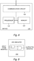
- FIG. 8 is a schematic block diagram illustrating an example of a device 100, based on a processor-memory implementation, according to an embodiment.
- the device 100 comprises a processor 110 and a memory 120, the memory 120 comprising instructions executable by the processor 110, whereby the processor is operative to identify presence of a wall of a building and trigger an adjustment of transmit power of the radio head 15 to align the radio head coverage with the wall.
- the arrangement/system 100 may also include a communication circuit 130.
- the communication circuit 130 may include functions for wired and/or wireless communication with other devices and/or network nodes in the network.
- the communication circuit 130 may be based on radio circuitry for communication with one or more other nodes, including transmitting and/or receiving information.
- the communication circuit 130 may be interconnected to the processor 110 and/or memory 120.
- the communication circuit 130 may include any of the following: a receiver, a transmitter, a transceiver, input/output (I/O) circuitry, input port(s) and/or output port(s).
- FIG. 9 is a schematic block diagram illustrating another example of a device 200, based on a hardware circuitry implementation, according to an embodiment.
- suitable hardware circuitry include one or more suitably configured or possibly reconfigurable electronic circuitry, e.g. Application Specific Integrated Circuits (ASICs), Field Programmable Gate Arrays (FPGAs), or any other hardware logic such as circuits based on discrete logic gates and/or flip-flops interconnected to perform specialized functions in connection with suitable registers (REG), and/or memory units (MEM) to identify presence of a wall of a building and trigger an adjustment of transmit power of the radio head 15 to align the radio head coverage with the wall.
- ASICs Application Specific Integrated Circuits
- FPGAs Field Programmable Gate Arrays
- REG suitable registers
- MCM memory units
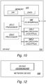
- FIG. 10 is a schematic block diagram illustrating yet another example of a device 300, based on combination of both processor(s) 310-1, 310-2 and hardware circuitry 330-1, 330-2 in connection with suitable memory unit(s) 320.
- the device 300 comprises one or more processors 310-1, 310-2, memory 320 including storage for software and data, and one or more units of hardware circuitry 330-1, 330-2 such as ASICs and/or FPGAs.
- the overall functionality is thus partitioned between programmed software, SW, for execution on one or more processors 310-1, 310-2, and one or more pre-configured or possibly reconfigurable hardware circuits 330-1, 330-2 such as ASICs and/or FPGAs.
- the actual hardware-software partitioning can be decided by a system designer based on a number of factors including processing speed, cost of implementation and other requirements.
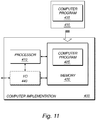
- FIG. 11 is a schematic diagram illustrating an example of a computer-implementation 400 according to an embodiment.
- a computer program 425; 435 which is loaded into the memory 420 for execution by processing circuitry including one or more processors 410.
- the processor(s) 410 and memory 420 are interconnected to each other to enable normal software execution.
- An optional input/output device 440 may also be interconnected to the processor(s) 410 and/or the memory 420 to enable input and/or output of relevant data such as input parameter(s) and/or resulting output parameter(s).
- processor' should be interpreted in a general sense as any system or device capable of executing program code or computer program instructions to perform a particular processing, determining or computing task.
- the processing circuitry including one or more processors 410 is thus configured to perform, when executing the computer program 425, well-defined processing tasks such as those described herein.
- the processing circuitry does not have to be dedicated to only execute the above-described steps, functions, procedure and/or blocks, but may also execute other tasks.
- the computer program 425; 435 comprises instructions, which when executed by at least one processor 410, cause the processor(s) 410 to:
- a carrier comprising the computer program, wherein the carrier is one of an electronic signal, an optical signal, an electromagnetic signal, a magnetic signal, an electric signal, a radio signal, a microwave signal, or a computer-readable storage medium.
- the software or computer program 425; 435 may be realized as a computer program product, which is normally carried or stored on a computer-readable medium 420; 430, in particular a non-volatile medium.
- the computer-readable medium may include one or more removable or non-removable memory devices including, but not limited to a Read-Only Memory (ROM), a Random Access Memory (RAM), a Compact Disc (CD), a Digital Versatile Disc (DVD), a Blu-ray disc, a Universal Serial Bus (USB) memory, a Hard Disk Drive (HDD) storage device, a flash memory, a magnetic tape, or any other conventional memory device.
- the computer program may thus be loaded into the operating memory of a computer or equivalent processing device for execution by the processing circuitry thereof.
- FIG. 12 is a schematic block diagram illustrating an example of a network device 500 comprising a device 100; 200; 300; 400 according to any of the embodiments.
- the network device 500 may be provided for location in a radio access network, a core network, an Operation and Support System, OSS, or a cloud-based network environment.
- the network device 500 may be a baseband unit 11 or an Indoor Radio Unit, IRU 13, and configured to send a power adjustment command to the radio head 15.
- the network device 500 may be a radio head 15 configured to obtain signal strength measurements for identifying presence of a wall of a building. This would be a slightly more advanced radio head, with internal processing capabilities.
- the network device may be any suitable network device in the wireless communication system, or a network device in connection with the wireless communication system.
- the network device 500 may be a cloud-based network device.
- an indoor radio system 10 comprising a device 100; 200; 300; 400 as described herein.
- the flow diagram or diagrams presented herein may be regarded as a computer flow diagram or diagrams, when performed by one or more processors.
- a corresponding apparatus may be defined as a group of function modules, where each step performed by the processor corresponds to a function module.
- the function modules are implemented as a computer program running on the processor.
- the computer program residing in memory may thus be organized as appropriate function modules configured to perform, when executed by the processor, at least part of the steps and/or tasks described herein.
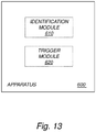
- FIG. 13 is a schematic diagram illustrating an example of an apparatus for enabling power adjustment of a radio head of an indoor radio system.
- the apparatus 600 comprises an identification module 610 for identifying, based on signal strength measurements in relation to wireless communication devices connected to the radio head, presence of a wall of a building in which the indoor radio system is located.
- the apparatus 600 also comprises a trigger module 620 for triggering an adjustment of transmit power of the radio head 15 to align the radio head coverage with the wall.
- module(s) in FIG. 13 it is possible to realize the module(s) in FIG. 13 predominantly by hardware modules, or alternatively by hardware, with suitable interconnections between relevant modules.
- Particular examples include one or more suitably configured digital signal processors and other known electronic circuits, e.g. discrete logic gates interconnected to perform a specialized function, and/or Application Specific Integrated Circuits (ASICs) as previously mentioned.
- Other examples of usable hardware include input/output (I/O) circuitry and/or circuitry for receiving and/or sending signals.
- I/O input/output
- FIG. 14 is a schematic diagram illustrating an example of a wireless communication system, including a radio access network 710 and/or a core network 720 and/or an Operations and Support System (OSS), 730 and/or a cloud-based network environment 740.
- OSS Operations and Support System
- the network device 500 may be provided for location in the radio access network 710, the core network 720, the OSS system 730 or the cloud-based network environment 740, with suitable transfer of information to the radio access network for enabling the power adjustment of the radio head(s).
- computing services can be distributed or re-located to one or more separate physical nodes or servers.
- the functionality may be re-located or distributed to one or more jointly acting physical and/or virtual machines that can be positioned in separate physical node(s), i.e. in the so-called cloud.
- cloud computing is a model for enabling ubiquitous on-demand network access to a pool of configurable computing resources such as networks, servers, storage, applications and general or customized services.
- a Network Device may generally be seen as an electronic device being communicatively connected to other electronic devices in the network.
- the network device may be implemented in hardware, software or a combination thereof.
- the network device may be a special-purpose network device or a general purpose network device, or a hybrid thereof.
- a special-purpose network device may use custom processing circuits and a proprietary operating system (OS), for execution of software to provide one or more of the features or functions disclosed herein.
- OS operating system
- a general purpose network device may use common off-the-shelf (COTS) processors and a standard OS, for execution of software configured to provide one or more of the features or functions disclosed herein.
- COTS off-the-shelf
- a special-purpose network device may include hardware comprising processing or computing resource(s), which typically include a set of one or more processors, and physical network interfaces (NIs), which sometimes are called physical ports, as well as non-transitory machine readable storage media having stored thereon software.
- a physical NI may be seen as hardware in a network device through which a network connection is made, e.g. wirelessly through a wireless network interface controller (WNIC) or through plugging in a cable to a physical port connected to a network interface controller (NIC).
- WNIC wireless network interface controller
- NIC network interface controller
- the software may be executed by the hardware to instantiate a set of one or more software instance(s).
- Each of the software instance(s), and that part of the hardware that executes that software instance may form a separate virtual network element.
- a general purpose network device may for example include hardware comprising a set of one or more processor(s), often COTS processors, and network interface controller(s) (NICs), as well as non-transitory machine readable storage media having stored thereon software.
- the processor(s) executes the software to instantiate one or more sets of one or more applications.
- one embodiment does not implement virtualization, alternative embodiments may use different forms of virtualization - for example represented by a virtualization layer and software containers.
- one such alternative embodiment implements operating system-level virtualization, in which case the virtualization layer represents the kernel of an operating system (or a shim executing on a base operating system) that allows for the creation of multiple software containers that may each be used to execute one of a sets of applications.
- each of the software containers also called virtualization engines, virtual private servers, or jails
- a user space instance typically a virtual memory space.
- the virtualization layer represents a hypervisor (sometimes referred to as a Virtual Machine Monitor (VMM)) or the hypervisor is executed on top of a host operating system; and 2) the software containers each represent a tightly isolated form of software container called a virtual machine that is executed by the hypervisor and may include a guest operating system.
- VMM Virtual Machine Monitor
- a hypervisor is the software/hardware that is responsible for creating and managing the various virtualized instances and in some cases the actual physical hardware.
- the hypervisor manages the underlying resources and presents them as virtualized instances. What the hypervisor virtualizes to appear as a single processor may actually comprise multiple separate processors. From the perspective of the operating system, the virtualized instances appear to be actual hardware components.
- a virtual machine is a software implementation of a physical machine that runs programs as if they were executing on a physical, non-virtualized machine; and applications generally do not know they are running on a virtual machine as opposed to running on a "bare metal" host electronic device, though some systems provide para-virtualization which allows an operating system or application to be aware of the presence of virtualization for optimization purposes.
- the instantiation of the one or more sets of one or more applications as well as the virtualization layer and software containers if implemented, are collectively referred to as software instance(s).
- Each set of applications, corresponding software container if implemented, and that part of the hardware that executes them (be it hardware dedicated to that execution and/or time slices of hardware temporally shared by software containers), forms a separate virtual network element(s).
- the virtual network element(s) may perform similar functionality compared to Virtual Network Element(s) (VNEs). This virtualization of the hardware is sometimes referred to as Network Function Virtualization (NFV)).
- NFV Network Function Virtualization
- NFV may be used to consolidate many network equipment types onto industry standard high volume server hardware, physical switches, and physical storage, which could be located in data centers, NDs, and Customer Premise Equipment (CPE).
- CPE Customer Premise Equipment
- different embodiments may implement one or more of the software container(s) differently.
- a hybrid network device which includes both custom processing circuitry/proprietary OS and COTS processors/standard OS in a network device, e.g. in a card or circuit board within a network device ND.
- a platform Virtual Machine such as a VM that implements functionality of a special-purpose network device, could provide for para-virtualization to the hardware present in the hybrid network device.
Landscapes
- Engineering & Computer Science (AREA)
- Computer Networks & Wireless Communication (AREA)
- Signal Processing (AREA)
- Mobile Radio Communication Systems (AREA)
Claims (18)
- Procédé pour permettre un ajustement de puissance d'une tête radio (15) d'un système radio intérieur (10), dans lequel ledit procédé comprend :- l'identification (S1), sur la base de mesures de force de signal par rapport à des dispositifs de communication sans fil connectés à la tête radio (15), de la présence d'un mur d'un bâtiment dans lequel le système radio intérieur (10) se situe ;- la création d'une distribution statistique sur la base des mesures de force de signal ;- l'identification d'un emplacement du mur dans la distribution statistique, dans lequel le mur est identifié à partir de niveaux moins fréquents de force de signal dans la distribution statistique ; et- le déclenchement (S2) d'un ajustement de puissance de transmission de la tête radio (15) pour aligner la couverture de tête radio avec le mur, dans lequel l'ajustement de puissance de transmission est déterminé sur la base de l'emplacement du mur identifié dans la distribution statistique.
- Procédé selon la revendication 1, dans lequel le système radio intérieur (10) comprend au moins deux têtes radio, et l'identification et le déclenchement sont mis en œuvre par tête radio.
- Procédé selon la revendication 1 ou 2, dans lequel l'ajustement de puissance de transmission est déclenché pour fournir une couverture intérieure, mais pas une couverture extérieure.
- Procédé selon l'une quelconque des revendications 1 à 3, dans lequel les mesures de force de signal incluent des mesures de force de signal de liaison montante et/ou des mesures de force de signal de liaison descendante et/ou des mesures d'affaiblissement de propagation, se rapportant à la tête radio.
- Procédé selon l'une quelconque des revendications 1 à 4, dans lequel le mur est identifié également sur la base de mesures de force de signal se rapportant à au moins une autre cellule.
- Procédé selon la revendication 5, dans lequel le mur est en outre identifié sur la base d'une mesure de géométrie définie en tant que relation entre une force de signal se rapportant à la tête radio et une force de signal d'au moins une autre cellule.
- Procédé selon la revendication 6, dans lequel le mur est en outre identifié sur la base d'une mesure de géométrie définie en tant que i) force de signal se rapportant à la tête radio divisée par la force de signal de la cellule extérieure la plus forte, ou ii) force de signal se rapportant à la tête radio divisée par la somme de toutes les autres forces de signal.
- Procédé selon l'une quelconque des revendications 1 à 7, dans lequel l'ajustement de puissance de transmission est déterminé pour localiser un bord de la couverture de tête radio de chaque côté du mur, ou au sein du mur.
- Procédé selon l'une quelconque des revendications 1 à 8, dans lequel le mur est un mur extérieur du bâtiment.
- Dispositif (100 ; 200 ; 300 ; 400) configuré pour permettre un ajustement de puissance d'une tête radio (15) d'un système radio intérieur (10), dans lequel ledit dispositif est configuré pour :identifier, sur la base de mesures de force de signal par rapport à des dispositifs de communication sans fil connectés à la tête radio (15), la présence d'un mur d'un bâtiment dans lequel le système radio intérieur (10) se situe ;créer une distribution statistique sur la base des mesures de force de signal ;identifier un emplacement du mur dans la distribution statistique, dans lequel le mur est identifié à partir de niveaux moins fréquents de force de signal dans la distribution statistique ; etdéclencher un ajustement de puissance de transmission de la tête radio (15) pour aligner la couverture de tête radio avec le mur, dans lequel l'ajustement de puissance de transmission est déterminé sur la base de l'emplacement du mur identifié dans la distribution statistique.
- Dispositif selon la revendication 10, dans lequel le système radio intérieur (10) comprend au moins deux têtes radio, et le dispositif est configuré pour identifier un mur et déclencher un ajustement de puissance correspondant par tête radio.
- Dispositif selon la revendication 10 ou 11, dans lequel le dispositif est configuré pour déclencher un ajustement de puissance de transmission pour fournir une couverture intérieure, mais pas une couverture extérieure.
- Dispositif selon l'une quelconque des revendications 10 à 12, dans lequel le dispositif est configuré pour fonctionner sur la base de mesures de force de signal de liaison montante et/ou de mesures de force de signal de liaison descendante et/ou de mesures d'affaiblissement de propagation, se rapportant à la tête radio.
- Dispositif selon l'une quelconque des revendications 10 à 13, dans lequel le dispositif est configuré pour identifier le mur également sur la base de mesures de force de signal se rapportant à au moins une autre cellule.
- Dispositif selon la revendication 14, dans lequel le dispositif est en outre configuré pour identifier le mur sur la base d'une mesure de géométrie définie en tant que relation entre une force de signal se rapportant à la tête radio et une force de signal d'au moins une autre cellule.
- Dispositif selon la revendication 15, dans lequel le dispositif est en outre configuré pour identifier le mur sur la base d'une mesure de géométrie définie en tant que i) force de signal se rapportant à la tête radio divisée par la force de signal de la cellule extérieure la plus forte, ou ii) force de signal se rapportant à la tête radio divisée par la somme de toutes les autres forces de signal.
- Dispositif selon l'une quelconque des revendications 10 à 16, dans lequel le dispositif est configuré pour déterminer l'ajustement de puissance de transmission pour localiser un bord de la couverture de tête radio de chaque côté du mur, ou au sein du mur.
- Dispositif selon l'une quelconque des revendications 10 à 17, dans lequel le dispositif est configuré pour identifier la présence d'un mur extérieur du bâtiment.
Applications Claiming Priority (1)
| Application Number | Priority Date | Filing Date | Title |
|---|---|---|---|
| PCT/SE2015/051137 WO2017074231A1 (fr) | 2015-10-28 | 2015-10-28 | Réglage de puissance d'une tête radio d'un système radio d'intérieur |
Publications (3)
| Publication Number | Publication Date |
|---|---|
| EP3369273A1 EP3369273A1 (fr) | 2018-09-05 |
| EP3369273A4 EP3369273A4 (fr) | 2018-10-17 |
| EP3369273B1 true EP3369273B1 (fr) | 2020-04-15 |
Family
ID=58630813
Family Applications (1)
| Application Number | Title | Priority Date | Filing Date |
|---|---|---|---|
| EP15907397.2A Active EP3369273B1 (fr) | 2015-10-28 | 2015-10-28 | Réglage de puissance d'une tête radio d'un système radio d'intérieur |
Country Status (3)
| Country | Link |
|---|---|
| US (1) | US10524210B2 (fr) |
| EP (1) | EP3369273B1 (fr) |
| WO (1) | WO2017074231A1 (fr) |
Families Citing this family (1)
| Publication number | Priority date | Publication date | Assignee | Title |
|---|---|---|---|---|
| US11277800B1 (en) * | 2020-03-19 | 2022-03-15 | Sprint Communications Company L.P. | Wireless access node uplink power control based on uplink error rate |
Citations (1)
| Publication number | Priority date | Publication date | Assignee | Title |
|---|---|---|---|---|
| US20130237227A1 (en) * | 2012-03-09 | 2013-09-12 | Qualcomm Incorporated | Method and system for resource allocation based on femtocell location classification |
Family Cites Families (4)
| Publication number | Priority date | Publication date | Assignee | Title |
|---|---|---|---|---|
| US8213978B1 (en) * | 2005-08-29 | 2012-07-03 | At&T Mobility Ii Llc | Estimating mobile local propagation environment characteristics for wireless communications |
| EP2332375B1 (fr) | 2008-09-29 | 2018-08-15 | Nokia Solutions and Networks Oy | Appareil, procédé, système et programme de commande de puissance ou de réglage de puissance |
| US9913239B2 (en) | 2012-03-09 | 2018-03-06 | Qualcomm Incorporated | Method and system for determining location of mobile devices in a femtocell |
| US9763054B2 (en) * | 2015-08-19 | 2017-09-12 | Locix Inc. | Systems and methods for determining locations of wireless sensor nodes in a tree network architecture having mesh-based features |
-
2015
- 2015-10-28 US US15/759,551 patent/US10524210B2/en active Active
- 2015-10-28 EP EP15907397.2A patent/EP3369273B1/fr active Active
- 2015-10-28 WO PCT/SE2015/051137 patent/WO2017074231A1/fr not_active Ceased
Patent Citations (1)
| Publication number | Priority date | Publication date | Assignee | Title |
|---|---|---|---|---|
| US20130237227A1 (en) * | 2012-03-09 | 2013-09-12 | Qualcomm Incorporated | Method and system for resource allocation based on femtocell location classification |
Non-Patent Citations (1)
| Title |
|---|
| JINYEOL ROH ET AL: "Adaptive In-building Propagation Simulator using ray tracing in WCDMA networks", TENCON 2008 - 2008, TENCON 2008. IEEE REGION 10 CONFERENCE, IEEE, PISCATAWAY, NJ, USA, 19 November 2008 (2008-11-19), pages 1 - 5, XP031414273, ISBN: 978-1-4244-2408-5 * |
Also Published As
| Publication number | Publication date |
|---|---|
| EP3369273A4 (fr) | 2018-10-17 |
| US10524210B2 (en) | 2019-12-31 |
| US20180242258A1 (en) | 2018-08-23 |
| EP3369273A1 (fr) | 2018-09-05 |
| WO2017074231A1 (fr) | 2017-05-04 |
Similar Documents
| Publication | Publication Date | Title |
|---|---|---|
| US9986453B2 (en) | Measurement configuration of wireless communication devices | |
| WO2023115567A1 (fr) | Procédés, dispositifs et support lisible par ordinateur pour la communication | |
| US10708025B2 (en) | Managing reference signals in a wireless communication network | |
| CN113273254A (zh) | 用于测量配置的功耗降低方法 | |
| CN107431589B (zh) | 用于处理和分配上行链路导频的方法和设备 | |
| US20190098643A1 (en) | Secondary serving cell selection for a wireless communication device | |
| US10917895B2 (en) | Power control method and apparatus | |
| EP3576472B1 (fr) | Procédé et appareil d'attribution de ressources, dispositif de réseau, et support de stockage | |
| EP3576375B1 (fr) | Commander des dispositifs de réseau et envoyer des informations ou des données de commande | |
| CN110710134B (zh) | 无线通信中飞行器的抗干扰 | |
| EP3369273B1 (fr) | Réglage de puissance d'une tête radio d'un système radio d'intérieur | |
| CN111512662B (zh) | 用于标识通信系统内的干扰飞行器用户设备的方法、系统和装置 | |
| US12562800B2 (en) | Apparatus and method to perform a beam alignment procedure based on an estimated time-of-stay | |
| EP3304961B1 (fr) | Procédé et appareil de configuration de cellule | |
| CN115053464B (zh) | 多个传输点下的波束选择 | |
| KR102368827B1 (ko) | 안테나의 최적 각도를 결정하는 방법 및 장치 | |
| WO2025199915A1 (fr) | Procédé et appareil pour déterminer des faisceaux prédits à rapporter | |
| US20240305975A1 (en) | Systems and methods for user equipment transfer return management | |
| WO2025171501A1 (fr) | Dispositifs et procédés de communication | |
| WO2024148542A1 (fr) | Procédés, dispositifs et support de communication | |
| WO2025199714A1 (fr) | Dispositifs et procédés de communication | |
| CN115396973A (zh) | 上行干扰抑制方法、装置及存储介质 |
Legal Events
| Date | Code | Title | Description |
|---|---|---|---|
| STAA | Information on the status of an ep patent application or granted ep patent |
Free format text: STATUS: THE INTERNATIONAL PUBLICATION HAS BEEN MADE |
|
| PUAI | Public reference made under article 153(3) epc to a published international application that has entered the european phase |
Free format text: ORIGINAL CODE: 0009012 |
|
| STAA | Information on the status of an ep patent application or granted ep patent |
Free format text: STATUS: REQUEST FOR EXAMINATION WAS MADE |
|
| 17P | Request for examination filed |
Effective date: 20180305 |
|
| AK | Designated contracting states |
Kind code of ref document: A1 Designated state(s): AL AT BE BG CH CY CZ DE DK EE ES FI FR GB GR HR HU IE IS IT LI LT LU LV MC MK MT NL NO PL PT RO RS SE SI SK SM TR |
|
| AX | Request for extension of the european patent |
Extension state: BA ME |
|
| STAA | Information on the status of an ep patent application or granted ep patent |
Free format text: STATUS: EXAMINATION IS IN PROGRESS |
|
| A4 | Supplementary search report drawn up and despatched |
Effective date: 20180917 |
|
| RIC1 | Information provided on ipc code assigned before grant |
Ipc: H04W 52/04 20090101AFI20180911BHEP Ipc: H04W 24/02 20090101ALI20180911BHEP |
|
| 17Q | First examination report despatched |
Effective date: 20181009 |
|
| DAV | Request for validation of the european patent (deleted) | ||
| DAX | Request for extension of the european patent (deleted) | ||
| GRAP | Despatch of communication of intention to grant a patent |
Free format text: ORIGINAL CODE: EPIDOSNIGR1 |
|
| STAA | Information on the status of an ep patent application or granted ep patent |
Free format text: STATUS: GRANT OF PATENT IS INTENDED |
|
| INTG | Intention to grant announced |
Effective date: 20200206 |
|
| GRAS | Grant fee paid |
Free format text: ORIGINAL CODE: EPIDOSNIGR3 |
|
| GRAA | (expected) grant |
Free format text: ORIGINAL CODE: 0009210 |
|
| STAA | Information on the status of an ep patent application or granted ep patent |
Free format text: STATUS: THE PATENT HAS BEEN GRANTED |
|
| AK | Designated contracting states |
Kind code of ref document: B1 Designated state(s): AL AT BE BG CH CY CZ DE DK EE ES FI FR GB GR HR HU IE IS IT LI LT LU LV MC MK MT NL NO PL PT RO RS SE SI SK SM TR |
|
| REG | Reference to a national code |
Ref country code: CH Ref legal event code: EP |
|
| REG | Reference to a national code |
Ref country code: DE Ref legal event code: R096 Ref document number: 602015050950 Country of ref document: DE |
|
| REG | Reference to a national code |
Ref country code: IE Ref legal event code: FG4D |
|
| REG | Reference to a national code |
Ref country code: AT Ref legal event code: REF Ref document number: 1258764 Country of ref document: AT Kind code of ref document: T Effective date: 20200515 |
|
| REG | Reference to a national code |
Ref country code: NL Ref legal event code: MP Effective date: 20200415 |
|
| REG | Reference to a national code |
Ref country code: LT Ref legal event code: MG4D |
|
| PG25 | Lapsed in a contracting state [announced via postgrant information from national office to epo] |
Ref country code: NL Free format text: LAPSE BECAUSE OF FAILURE TO SUBMIT A TRANSLATION OF THE DESCRIPTION OR TO PAY THE FEE WITHIN THE PRESCRIBED TIME-LIMIT Effective date: 20200415 Ref country code: PT Free format text: LAPSE BECAUSE OF FAILURE TO SUBMIT A TRANSLATION OF THE DESCRIPTION OR TO PAY THE FEE WITHIN THE PRESCRIBED TIME-LIMIT Effective date: 20200817 Ref country code: LT Free format text: LAPSE BECAUSE OF FAILURE TO SUBMIT A TRANSLATION OF THE DESCRIPTION OR TO PAY THE FEE WITHIN THE PRESCRIBED TIME-LIMIT Effective date: 20200415 Ref country code: GR Free format text: LAPSE BECAUSE OF FAILURE TO SUBMIT A TRANSLATION OF THE DESCRIPTION OR TO PAY THE FEE WITHIN THE PRESCRIBED TIME-LIMIT Effective date: 20200716 Ref country code: SE Free format text: LAPSE BECAUSE OF FAILURE TO SUBMIT A TRANSLATION OF THE DESCRIPTION OR TO PAY THE FEE WITHIN THE PRESCRIBED TIME-LIMIT Effective date: 20200415 Ref country code: FI Free format text: LAPSE BECAUSE OF FAILURE TO SUBMIT A TRANSLATION OF THE DESCRIPTION OR TO PAY THE FEE WITHIN THE PRESCRIBED TIME-LIMIT Effective date: 20200415 Ref country code: NO Free format text: LAPSE BECAUSE OF FAILURE TO SUBMIT A TRANSLATION OF THE DESCRIPTION OR TO PAY THE FEE WITHIN THE PRESCRIBED TIME-LIMIT Effective date: 20200715 Ref country code: IS Free format text: LAPSE BECAUSE OF FAILURE TO SUBMIT A TRANSLATION OF THE DESCRIPTION OR TO PAY THE FEE WITHIN THE PRESCRIBED TIME-LIMIT Effective date: 20200815 |
|
| REG | Reference to a national code |
Ref country code: AT Ref legal event code: MK05 Ref document number: 1258764 Country of ref document: AT Kind code of ref document: T Effective date: 20200415 |
|
| PG25 | Lapsed in a contracting state [announced via postgrant information from national office to epo] |
Ref country code: HR Free format text: LAPSE BECAUSE OF FAILURE TO SUBMIT A TRANSLATION OF THE DESCRIPTION OR TO PAY THE FEE WITHIN THE PRESCRIBED TIME-LIMIT Effective date: 20200415 Ref country code: RS Free format text: LAPSE BECAUSE OF FAILURE TO SUBMIT A TRANSLATION OF THE DESCRIPTION OR TO PAY THE FEE WITHIN THE PRESCRIBED TIME-LIMIT Effective date: 20200415 Ref country code: BG Free format text: LAPSE BECAUSE OF FAILURE TO SUBMIT A TRANSLATION OF THE DESCRIPTION OR TO PAY THE FEE WITHIN THE PRESCRIBED TIME-LIMIT Effective date: 20200715 Ref country code: LV Free format text: LAPSE BECAUSE OF FAILURE TO SUBMIT A TRANSLATION OF THE DESCRIPTION OR TO PAY THE FEE WITHIN THE PRESCRIBED TIME-LIMIT Effective date: 20200415 |
|
| PG25 | Lapsed in a contracting state [announced via postgrant information from national office to epo] |
Ref country code: AL Free format text: LAPSE BECAUSE OF FAILURE TO SUBMIT A TRANSLATION OF THE DESCRIPTION OR TO PAY THE FEE WITHIN THE PRESCRIBED TIME-LIMIT Effective date: 20200415 |
|
| REG | Reference to a national code |
Ref country code: DE Ref legal event code: R097 Ref document number: 602015050950 Country of ref document: DE |
|
| PG25 | Lapsed in a contracting state [announced via postgrant information from national office to epo] |
Ref country code: SM Free format text: LAPSE BECAUSE OF FAILURE TO SUBMIT A TRANSLATION OF THE DESCRIPTION OR TO PAY THE FEE WITHIN THE PRESCRIBED TIME-LIMIT Effective date: 20200415 Ref country code: EE Free format text: LAPSE BECAUSE OF FAILURE TO SUBMIT A TRANSLATION OF THE DESCRIPTION OR TO PAY THE FEE WITHIN THE PRESCRIBED TIME-LIMIT Effective date: 20200415 Ref country code: AT Free format text: LAPSE BECAUSE OF FAILURE TO SUBMIT A TRANSLATION OF THE DESCRIPTION OR TO PAY THE FEE WITHIN THE PRESCRIBED TIME-LIMIT Effective date: 20200415 Ref country code: RO Free format text: LAPSE BECAUSE OF FAILURE TO SUBMIT A TRANSLATION OF THE DESCRIPTION OR TO PAY THE FEE WITHIN THE PRESCRIBED TIME-LIMIT Effective date: 20200415 Ref country code: ES Free format text: LAPSE BECAUSE OF FAILURE TO SUBMIT A TRANSLATION OF THE DESCRIPTION OR TO PAY THE FEE WITHIN THE PRESCRIBED TIME-LIMIT Effective date: 20200415 Ref country code: CZ Free format text: LAPSE BECAUSE OF FAILURE TO SUBMIT A TRANSLATION OF THE DESCRIPTION OR TO PAY THE FEE WITHIN THE PRESCRIBED TIME-LIMIT Effective date: 20200415 Ref country code: IT Free format text: LAPSE BECAUSE OF FAILURE TO SUBMIT A TRANSLATION OF THE DESCRIPTION OR TO PAY THE FEE WITHIN THE PRESCRIBED TIME-LIMIT Effective date: 20200415 Ref country code: DK Free format text: LAPSE BECAUSE OF FAILURE TO SUBMIT A TRANSLATION OF THE DESCRIPTION OR TO PAY THE FEE WITHIN THE PRESCRIBED TIME-LIMIT Effective date: 20200415 |
|
| PLBE | No opposition filed within time limit |
Free format text: ORIGINAL CODE: 0009261 |
|
| STAA | Information on the status of an ep patent application or granted ep patent |
Free format text: STATUS: NO OPPOSITION FILED WITHIN TIME LIMIT |
|
| PG25 | Lapsed in a contracting state [announced via postgrant information from national office to epo] |
Ref country code: PL Free format text: LAPSE BECAUSE OF FAILURE TO SUBMIT A TRANSLATION OF THE DESCRIPTION OR TO PAY THE FEE WITHIN THE PRESCRIBED TIME-LIMIT Effective date: 20200415 Ref country code: SK Free format text: LAPSE BECAUSE OF FAILURE TO SUBMIT A TRANSLATION OF THE DESCRIPTION OR TO PAY THE FEE WITHIN THE PRESCRIBED TIME-LIMIT Effective date: 20200415 |
|
| 26N | No opposition filed |
Effective date: 20210118 |
|
| PG25 | Lapsed in a contracting state [announced via postgrant information from national office to epo] |
Ref country code: SI Free format text: LAPSE BECAUSE OF FAILURE TO SUBMIT A TRANSLATION OF THE DESCRIPTION OR TO PAY THE FEE WITHIN THE PRESCRIBED TIME-LIMIT Effective date: 20200415 |
|
| REG | Reference to a national code |
Ref country code: CH Ref legal event code: PL |
|
| PG25 | Lapsed in a contracting state [announced via postgrant information from national office to epo] |
Ref country code: LU Free format text: LAPSE BECAUSE OF NON-PAYMENT OF DUE FEES Effective date: 20201028 Ref country code: MC Free format text: LAPSE BECAUSE OF FAILURE TO SUBMIT A TRANSLATION OF THE DESCRIPTION OR TO PAY THE FEE WITHIN THE PRESCRIBED TIME-LIMIT Effective date: 20200415 |
|
| REG | Reference to a national code |
Ref country code: BE Ref legal event code: MM Effective date: 20201031 |
|
| PG25 | Lapsed in a contracting state [announced via postgrant information from national office to epo] |
Ref country code: LI Free format text: LAPSE BECAUSE OF NON-PAYMENT OF DUE FEES Effective date: 20201031 Ref country code: CH Free format text: LAPSE BECAUSE OF NON-PAYMENT OF DUE FEES Effective date: 20201031 Ref country code: BE Free format text: LAPSE BECAUSE OF NON-PAYMENT OF DUE FEES Effective date: 20201031 |
|
| PG25 | Lapsed in a contracting state [announced via postgrant information from national office to epo] |
Ref country code: IE Free format text: LAPSE BECAUSE OF NON-PAYMENT OF DUE FEES Effective date: 20201028 |
|
| PG25 | Lapsed in a contracting state [announced via postgrant information from national office to epo] |
Ref country code: TR Free format text: LAPSE BECAUSE OF FAILURE TO SUBMIT A TRANSLATION OF THE DESCRIPTION OR TO PAY THE FEE WITHIN THE PRESCRIBED TIME-LIMIT Effective date: 20200415 Ref country code: MT Free format text: LAPSE BECAUSE OF FAILURE TO SUBMIT A TRANSLATION OF THE DESCRIPTION OR TO PAY THE FEE WITHIN THE PRESCRIBED TIME-LIMIT Effective date: 20200415 Ref country code: CY Free format text: LAPSE BECAUSE OF FAILURE TO SUBMIT A TRANSLATION OF THE DESCRIPTION OR TO PAY THE FEE WITHIN THE PRESCRIBED TIME-LIMIT Effective date: 20200415 |
|
| PG25 | Lapsed in a contracting state [announced via postgrant information from national office to epo] |
Ref country code: MK Free format text: LAPSE BECAUSE OF FAILURE TO SUBMIT A TRANSLATION OF THE DESCRIPTION OR TO PAY THE FEE WITHIN THE PRESCRIBED TIME-LIMIT Effective date: 20200415 |
|
| PGFP | Annual fee paid to national office [announced via postgrant information from national office to epo] |
Ref country code: DE Payment date: 20251029 Year of fee payment: 11 |
|
| PGFP | Annual fee paid to national office [announced via postgrant information from national office to epo] |
Ref country code: GB Payment date: 20251027 Year of fee payment: 11 |
|
| PGFP | Annual fee paid to national office [announced via postgrant information from national office to epo] |
Ref country code: FR Payment date: 20251027 Year of fee payment: 11 |