EP3369348A1 - Récipient de ventes et de transport destiné à la présentation de marchandises - Google Patents
Récipient de ventes et de transport destiné à la présentation de marchandises Download PDFInfo
- Publication number
- EP3369348A1 EP3369348A1 EP18159163.7A EP18159163A EP3369348A1 EP 3369348 A1 EP3369348 A1 EP 3369348A1 EP 18159163 A EP18159163 A EP 18159163A EP 3369348 A1 EP3369348 A1 EP 3369348A1
- Authority
- EP
- European Patent Office
- Prior art keywords
- bottom wall
- sales
- transport container
- container according
- adjusting device
- Prior art date
- Legal status (The legal status is an assumption and is not a legal conclusion. Google has not performed a legal analysis and makes no representation as to the accuracy of the status listed.)
- Granted
Links
Images









Classifications
-
- A—HUMAN NECESSITIES
- A47—FURNITURE; DOMESTIC ARTICLES OR APPLIANCES; COFFEE MILLS; SPICE MILLS; SUCTION CLEANERS IN GENERAL
- A47F—SPECIAL FURNITURE, FITTINGS, OR ACCESSORIES FOR SHOPS, STOREHOUSES, BARS, RESTAURANTS OR THE LIKE; PAYING COUNTERS
- A47F5/00—Show stands, hangers, or shelves characterised by their constructional features
- A47F5/10—Adjustable or foldable or dismountable display stands
- A47F5/13—Adjustable or foldable or dismountable display stands made of tubes or wire
-
- A—HUMAN NECESSITIES
- A47—FURNITURE; DOMESTIC ARTICLES OR APPLIANCES; COFFEE MILLS; SPICE MILLS; SUCTION CLEANERS IN GENERAL
- A47F—SPECIAL FURNITURE, FITTINGS, OR ACCESSORIES FOR SHOPS, STOREHOUSES, BARS, RESTAURANTS OR THE LIKE; PAYING COUNTERS
- A47F3/00—Show cases or show cabinets
- A47F3/14—Display trays or containers
- A47F3/142—Display trays to be placed on the floor, e.g. by means of legs or of integrated cabinets underneath
-
- A—HUMAN NECESSITIES
- A47—FURNITURE; DOMESTIC ARTICLES OR APPLIANCES; COFFEE MILLS; SPICE MILLS; SUCTION CLEANERS IN GENERAL
- A47F—SPECIAL FURNITURE, FITTINGS, OR ACCESSORIES FOR SHOPS, STOREHOUSES, BARS, RESTAURANTS OR THE LIKE; PAYING COUNTERS
- A47F3/00—Show cases or show cabinets
- A47F3/14—Display trays or containers
- A47F3/147—Display trays or containers made of tubes or wire
Definitions
- the invention relates to a sales and transport container for the presentation of goods, which is designed in the form of a lattice table according to the preamble of claim 1.
- Containers in the form of mobile lattice tables intended for use in sales rooms are designed both for the transport and for the presentation of goods. This is already in DE 76 28 135 U1
- a container for receiving goods has been proposed, whose particular formed by partially transparent grid plates side parts define a variable interpretable usable space in which a provided for filing the goods bottom wall part can be introduced.
- this bottom wall is provided with lateral support hooks o.
- Connectors so that in the region of respective assigned grating structures on the side walls a positive fixing is possible.
- a change in height for the bottom wall is possible, so that increases in useful space or reductions for different goods can be carried out.
- a device for presenting merchandise is defined as a table for self-service shops.
- a bottom wall to be taken out of the work space is provided, so that the table can be collapsed thereafter.
- a total executed as a removable unit execution of the sales and transport container is in DE 20 2013 009 631 U1 shown, in which case the bottom wall can also be connected via form-fitting support connector with the side panels and additional transverse webs a subdivision of the effective area above allow the bottom wall.
- a collapsible variant of a lattice table with removable bottom wall is in EP 1 640 281 A1 shown.
- the invention is concerned with the problem of designing a sales and transport container designed as a lattice so that with little technical effort a quick adjustment of the container interior to different size or weight having goods is possible and with damage access conditions for operators and customers a damage-proof Supporting the goods is achieved.
- the system is designed so that the bottom wall connected to the actuator can be operated by hand, by foot and / or by means of at least one actuator. Due to different variants of the actuations, an optimal operation of the functionally expanded transport container is then possible for the place of installation.
- the concept of the displaceable with an actuator bottom wall is directed that for each supported on these goods, at least in the region of an open top of the usable space each variable access and use positions can be specified. This is particularly indicated when different sized goods or items are to handle with great weight.
- the system can also be extended by the fact that at least one of the useful space limiting side walls can be moved to an open position. This then also lateral access conditions for the lattice table can be reached, so that when loading and / or unloading of the usable space as low lifting heights as possible for easier handling of the goods. It is conceivable that at least one of the side walls is formed from at least two partial walls, of which at least one can be displaced into an open position. By corresponding reduction of the subregions different sized side openings can thus be produced, and in this area, the bottom wall can be positioned with the adjusting device in an optimal operating height.
- the bottom wall forming a usable surface parallel to the horizontal ground plane at the installation location is preferably adjustable to different altitudes within the useful space by means of the adjusting device. It is also conceivable that by means of the adjusting device, a displacement of the bottom wall can be carried out to beyond the upper edge of the opening of the lattice table and a lowering movement into the work space is introduced into it.
- the bottom wall is held tiltable in the region of the adjusting device. This ensures that the at least accessible from the top of the open space for the customer goods are presentable on an at least partially inclined floor space and thus a removal-friendly access position is defined.
- the adjusting device is designed so that the at least partially horizontally extending or tilted position of use occupying bottom wall can be stepped or continuously moved.
- the connectable to the actuator bottom wall can be carried out with separate sections so that a multipart floor space is created.
- the at least two partial regions can also be displaced individually by means of the at least one adjusting device.
- the bottom wall also has more than two partial areas can have.
- each subarea of the bottom wall is assigned in each case one adjusting device.
- two upper side useful sub-surface engaging under adjusting devices can be introduced into a side wall structure of the lattice table.
- the at least one assembly of bottom wall and adjusting device is designed as a self-sufficient unit. This can also be used independently of the lattice table. For this purpose, it is conceivable that the self-sufficient unit can be defined in a lying on the floor of the installation site use position and thus the bottom wall defines a "borderless" lattice table.
- the optimal implementation of the lattice table concept according to the invention provides that the assembly having the bottom wall has a usable position fixable in or on the components of the lattice table.
- the peripheral side wall structure of the lattice table is used for receiving the self-sufficient structural components of the adjusting device.
- a connecting construction of the adjusting device in the region of the corner-side support posts is conceivable.
- the adjusting device is preferably designed in the form of a scissor arm lift which engages under the bottom wall.
- This has at least two connected by a central support joint scissor arms of known design.
- these scissor arms by means of known fixed-bearing floating supports a displacement in different spreader positions can be mediated, such that thus a change in respective altitudes of the located at the upper ends of the scissor arms bottom wall is achieved.
- a structurally stable and expedient embodiment of this system provides that a respective Scherenarmheber is provided at two of the parallel side edges of the bottom wall. This ensures that the bottom wall can be moved parallel to the ground by means of pairs of pairs of scissor arms opposite each other.
- This low-cost integrated into the lattice table hub system provides that the respective floating bearing of the scissor arms are on the one hand in the region of a lower frame frame by means of engaging in a latching guide connecting strut in different Sp Dahlen fixed.
- a loose bearing of the scissor arm receiving longitudinal groove is provided in the region of the upper bottom wall, so that here a guided movement when adjusting the bottom wall is possible.
- the structural design of acting as an adjusting scissor arm provides that below the bottom wall, a the upper ends of the pair of scissor arms in both the floating bearing and the spaced-apart fixed bearing captive support frame is provided. This ensures that by means of an actuator located on this support frame respective lifting and / or tilting adjustments of the bottom wall can be performed.
- a second embodiment of the lattice table according to the invention with adjustment in the region of the bottom wall provides that this has an adjusting device which is provided with at least one directly acting on the bottom wall actuator.
- the general concept provides that the actuator can be held in the region of the container wall and / or the support posts.
- this direct-acting actuator in each case a force storage device in the form of a spring o. The like.
- the actuator is provided in the region of at least two of the corner-side support post.
- An advantageous simple embodiment of this spring-force accumulator is directed to the fact that in each case a prestressable compression spring is integrated into the system of the support posts. This in vertical mounting position in several of the support post integrable construction can cooperate at the upper end of the compression spring with a guide pinion, which in turn is to be connected to a rack provided in the support post.
- a counterforce generated by the prestressable compression spring can be stored. This is defined as a variably usable lifting force - in particular depending on the weight load generated by the goods in the bottom wall - defined in a lifting movement.
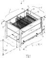
- Fig. 1 is a total of 1 designated sales and transport container for the presentation of goods in supermarkets o. The like. Sales facilities shown.
- the container 1 is provided with respective pairwise opposed vertical longitudinal and transverse side walls 2, 3, 4, 5, which are preferably connected in the region of corner-side support posts 6, 7, 8, 9.
- This constructed in the manner of a lattice container 1 defines a payload space N, in which at least one of the goods not shown in detail removal under cross-bottom wall 10 can be inserted.
- the bottom wall 10 can be moved at least in the unloaded state in different positions of use and fixed in these.
- the concept of the container construction according to the invention provides that now the bottom wall 10 is provided with at least one adjusting device 11 (FIG. Fig. 2 ) can be connected.
- the construction is designed so that the associated with the actuator 11 bottom wall 10 either by hand, by foot and / or by means of at least an actuator 12 ( Fig. 13 ) is displaceable.
- the concept of a displaceable by means of the adjusting device 11 bottom wall 10 is directed to that for goods to be supported at least in the region of an open top 13 of the usable space N variable access and use positions can be specified.
- a directly usable lifting system on the bottom wall 10 is illustrated. This is based on a concept in which the connectable to the bottom wall actuator 11 with a plurality - directly on the bottom wall 10 acting - actuators SG interacts. These actuators SG can both in the region of the container wall (not shown in detail) as well as in the area of at least one support post 7, 8 ( Fig. 3, Fig. 4 ).
- Fig. 2 a schematic diagram is shown, wherein the system has in respective corner regions of the bottom wall 10 of one of the actuators SG, which act as an actuator 11.
- respective compression springs 14 are provided at least in the region of pairwise interacting actuators SG as force accumulators, which are arranged in a vertical prestressing direction according to arrow D (FIG. Fig. 2 ) can be biased so that the actuators SG have a total "internal biasing force" and thus the bottom wall 10 can be acted upon.
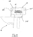
- this installation position of the bottom wall 10 is shown in conjunction with the actuators SG having a respective compression spring 14. It is provided that in the region of the actuator SG respectively an upper guide pinion 15 and a pivotally connectable to the bottom wall 10 brake pinion 16 cooperate (arrow A, A '; Fig. 6 ). These two pinions 15 and 16 'can engage in a respective profiling of two parallel racks 17, 17' so that in the installed position according to Fig. 5 a braking effect and thus fixation of the bottom wall 10 by means of a displaceable locking bolt RB is achieved.
- FIGS. 7 and 8 are the engagement conditions in the region of the two pinions 15 and 16 in connection with the two racks 17 and 17 'illustrated in more detail.
- Fig. 2 to Fig. 8 is a direct support of the bottom wall 10 of structural parts of the lattice table 1 shown only schematically.
- FIGS. 22 to 25 shown as a second embodiment for direct adjustment of the bottom wall 10.
- This manually executable adjustment of the system is possible here in that in the two parallel C-profiles CP (FIG. Fig. 22 ) each a rack profile 17 "( Fig. 25 ) is provided.
- a tilt according to arrow A ( Fig. 6 ) so that the displacement of the bottom 10 in the direction of arrow B is possible in the retaining pin HB unlocking from the insertion openings SG skew.
- a suitably roll-shaped contact part AG in the C-profile CP is guided so that a user-friendly guided displacement of the bottom 10 is possible and the pinion 16 defined in the rack 17 "can roll.
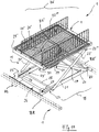
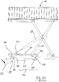
- a second embodiment of the bottom wall actuator combination provides that preferably one - from the schematic diagrams in FIGS. 9 to 18 more apparent - scissors arm 18 is used as adjusting device 11.
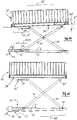
- the bottom wall 10 forming at least region-wise a horizontal wall H, which is parallel to the horizontal H - in a set-up space - by means of the adjusting device 11, can be moved to different altitudes F, F '(FIG. Fig. 16, Fig. 17 ) within the working space N can be fixed.
- FIGS. 12 and 13 A synopsis of FIGS. 12 and 13 shows that the bottom wall 10 is held tiltable in the upper region of the adjusting device 11. This is achieved the goods (not shown) that are openly accessible at least on the upper side 13 of the usable space N can be presented on an area E 'inclined at least in certain areas.
- the bottom wall 10 can be pivoted about a support point SP, for which purpose the application of an actuating device 12 -effective here independently of the actuating device 11 -is conceivable.
- the upper tilt position according to Fig. 13 is a fixation of the bottom wall 10 in the region of the actuator 12 or by means of a mechanical lock (not shown) conceivable.
- the bottom wall 10 occupying the at least partially horizontally extending or tilted positions of use can be combined with variable positioning systems. These are constructed so that in each case a stepped or continuous displacement and positioning of the components is conceivable.
- the bottom wall 10 may also have a multi-part effective area E. Shown here are at least two subregions T and T '( Fig. 9 ), which are individually displaceable by means of at least one respective adjusting device 11. It is also conceivable that the two subregions T, T 'have a common adjusting device (not shown).
- the above-described system of bottom wall 10 and adjusting device 11 in structurally simple and optimal for use design as a self-contained unit BE executable.
- Fig. 1 illustrated compact integration of the modules in the wall-post construction of a lattice table 1 is in the wall structure and an independent modular unit BE - according to Fig. 11 . Fig. 18 . Fig. 19 - applicable.
- the self-sufficient unit BE even without surrounding assemblies ( Fig. 9 . Fig. 20 ) is set in a directly on the floor H of a set-up room resting R use position (not shown).
- known lattice tables can be upgraded by the self-contained unit BE and thus the movable bottom wall 10 can be integrated into existing systems.
- the bottom wall 10 located on the adjusting device 11 can be defined as a functional assembly - instead of a direct bottom support - on the components BR, BR 'of the lattice table 1 known per se in a frame-side connecting position.
- This concept with frame-integrated adjusting device 11 is based on the representations according to Fig. 11 to Fig. 21 described in detail in detail.
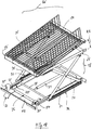
- Fig. 11 the expedient embodiment of the scissor arm lifter becomes clear, wherein the latter has on the parallel side edges 25, 25 'of the bottom wall 10 a respective partial scissor arm lifter 18, such that the bottom wall 10 can be displaced parallel to the ground by means of pairs of opposing scissor arms 20, 20' and 21, 21 ' is (arrow FF; Fig. 19 ).
- FIGS. 14 and 15 are the engagement conditions in the area of the floating bearings 23, 24 (23 ', 24') illustrates, which can be used by a combination of the longitudinal groove 29 'adjustable position of a scissor arm 20 with the engaging in the latch guide 27 other scissor arm 21 thereto , the bottom wall 10 in a the support plane E "forming inclination position KB '( Fig. 14 ) to relocate.
- 27 ' is at least one footrest 33 with retaining hook 33' and return spring 33 "integrated into the frame frame 26.
- a bracket VB is a connection between the two locking guides 27 and 27 'made ( Fig. 18 ).
- Fig. 19 In the execution according to Fig. 19 is - in place of the locking guide 27, Fig. 11 - Provided a lower guide groove 34, 34 'for the lower connecting strut 28 in the region of the floating bearing.
- This system is provided with two cylinders 35, 36 (movement arrow Z) held on the lower frame frame 26. With these provided as an actuator cylinder 35, 36, the continuous adjustment in the region of the scissor arms 20, 20 ', 21, 21' are triggered (arrow FF), so that the bottom wall 10 is moved by a motor in a designated position of use.
- FIGS. 20 and 21 is a further supplement of the above-described system 1 with the two parallel Scherenarmcruen the lifter 18 shown (similar FIGS. 9 and 10 ).
- 10 additional lifting springs 37 are arranged below the cooperating with the Scherenarmheber-adjusting devices bottom wall.
- the (in accordance with the embodiments shown in FIG Fig. 9 to Fig. 19 Comparable) Scherenarm system largely automatically after applying a bias - for example, by a resting weight according to arrow C '- be moved (arrow D'), so that an effective upon removal of goods Hubunterstützung (arrow FF ') is integrated into the lattice table 1 ,
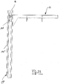
- An optimal loading and unloading position for the lattice table 1 with displaceable bottom wall 10 can be achieved in that at least one of the useful space N limiting side walls (here: wall 2, Fig. 1 ) in an open position displaced is, so that by lowering the upper part of the wall TW located in a "low position" bottom wall 10 is reached and thus the to be overcome in the loading or removal access height ZH can be kept low (ZH ', ZH ").
- FIGS. 26 to 28 is a second embodiment of the unit BE similar Fig. 18 with the detent adjustment in the area of the footrest 33 (FIG. Fig. 18 ).
- This system has a central gas pressure spring 38, which cooperates with the bottom-side adjusting system.
- the footrest 33 is connected via a transverse tube 39 with the two spring-loaded locking beams 40, 40 '.
- Upon actuation of the footrest 33 is carried out in each case an unlocking in the region of a profile groove 41 by the cross bar 42 of the Scherenarmismes in the position according to Fig. 28 arrives. This is in the direction of arrow RS a shift to the next of the profile grooves 41 out possible.
- This operating mechanism in the region of the latching carrier 40 is in each case provided with a pivot-controlled longitudinal strut 43, the end control legs 44, 45, the guide pin 46, 47 engages in a respective Nutbogen 48, 49.
- the scissors arm 21 having a support roller 50 is in each case held in a hollow profile carrier 51, so that a particularly simple height adjustment of the assembly BE is possible.
Landscapes
- Warehouses Or Storage Devices (AREA)
- Vending Machines For Individual Products (AREA)
Priority Applications (1)
| Application Number | Priority Date | Filing Date | Title |
|---|---|---|---|
| PL18159163T PL3369348T3 (pl) | 2017-03-01 | 2018-02-28 | Pojemnik do sprzedaży i transportu do prezentacji towarów |
Applications Claiming Priority (1)
| Application Number | Priority Date | Filing Date | Title |
|---|---|---|---|
| DE202017001134.4U DE202017001134U1 (de) | 2017-03-01 | 2017-03-01 | Verkaufs- und Transportbehälter zur Warenpräsentation |
Publications (2)
| Publication Number | Publication Date |
|---|---|
| EP3369348A1 true EP3369348A1 (fr) | 2018-09-05 |
| EP3369348B1 EP3369348B1 (fr) | 2020-10-28 |
Family
ID=61526599
Family Applications (1)
| Application Number | Title | Priority Date | Filing Date |
|---|---|---|---|
| EP18159163.7A Active EP3369348B1 (fr) | 2017-03-01 | 2018-02-28 | Récipient de ventes et de transport destiné à la présentation de marchandises |
Country Status (4)
| Country | Link |
|---|---|
| EP (1) | EP3369348B1 (fr) |
| DE (1) | DE202017001134U1 (fr) |
| ES (1) | ES2846306T3 (fr) |
| PL (1) | PL3369348T3 (fr) |
Cited By (1)
| Publication number | Priority date | Publication date | Assignee | Title |
|---|---|---|---|---|
| NL2038164B1 (en) * | 2024-07-08 | 2026-01-27 | Vlastuin Cdi B V | A display system, a base for such display system as well as a method for transporting and installing a display system |
Families Citing this family (4)
| Publication number | Priority date | Publication date | Assignee | Title |
|---|---|---|---|---|
| WO2020030381A1 (fr) | 2018-08-06 | 2020-02-13 | Wanzl Metallwarenfabrik Gmbh | Comptoir de vente |
| DE102018123584A1 (de) | 2018-09-25 | 2020-03-26 | Wanzl GmbH & Co. KGaA | Trennwandelement für einen Verkaufstisch sowie Verkaufstisch |
| FR3103801B1 (fr) * | 2019-11-29 | 2022-01-14 | Pa Cotte Sa | Colis comprenant des moyens de retenue d’un objet |
| EP4659631A1 (fr) * | 2024-06-07 | 2025-12-10 | Kesseböhmer Holding Kg | Récipient de vente et de transport pour l'approvisionnement et la présentation de marchandises |
Citations (14)
| Publication number | Priority date | Publication date | Assignee | Title |
|---|---|---|---|---|
| US1640405A (en) * | 1927-02-21 | 1927-08-30 | Union Steel Prod Co | Display receptacle |
| US3663078A (en) * | 1970-10-19 | 1972-05-16 | Insulating Fabricators Inc | Receptacle and improved floating platform therefor |
| DE7628135U1 (de) | 1976-09-08 | 1977-01-27 | Erni Max | Behaelter |
| DE2841772A1 (de) | 1977-09-27 | 1979-04-05 | Gerardus Cornelis Brinkers | Behaelter zum verpacken, ausstellen und anbieten von waren |
| WO1998035594A1 (fr) * | 1997-02-13 | 1998-08-20 | Herman Miller, Inc. | Etagere a barriere mobile |
| WO2004078003A1 (fr) * | 2003-03-03 | 2004-09-16 | Talon Customizing House Limited | Appareil de vente au detail de palettes et procede associe |
| EP1511411B1 (fr) | 2002-06-11 | 2005-10-26 | Wanzl Metallwarenfabrik Gmbh | Table pour magasins self-service |
| EP1640281A1 (fr) | 2004-09-18 | 2006-03-29 | Heinrich J. Kesseböhmer KG | Conteneur pliable de vente et de transport |
| DE202005006085U1 (de) | 2005-04-16 | 2006-08-31 | Heinrich J. Kesseböhmer KG | Gittertisch zur Warenpräsentation |
| WO2010012929A1 (fr) * | 2008-07-28 | 2010-02-04 | Caddie | Table a paroi de fond a crochets |
| DE202009006756U1 (de) | 2009-05-11 | 2010-09-23 | Heinrich J. Kesseböhmer KG | Gittertisch zur Warenpräsentation |
| DE202009006757U1 (de) | 2009-05-11 | 2010-09-23 | Heinrich J. Kesseböhmer KG | Gittertisch zur Warenpräsentation |
| DE202010003310U1 (de) | 2010-03-09 | 2011-09-09 | Heinrich J. Kesseböhmer KG | Zusammenlegbarer Verkaufsbehälter in Form eines Gittertisches |
| DE202013009631U1 (de) | 2013-10-31 | 2013-12-04 | Kesseböhmer Holding e.K. | Verkaufs- und Transportbehälter zur Warenpräsentation |
Family Cites Families (3)
| Publication number | Priority date | Publication date | Assignee | Title |
|---|---|---|---|---|
| US2717085A (en) * | 1950-10-20 | 1955-09-06 | American Mach & Foundry | Self-leveling, storing and dispensing apparatus |
| FR2633589B1 (fr) * | 1988-06-29 | 1991-04-12 | Safil | Conteneur presentoir |
| US20040000260A1 (en) * | 2002-06-28 | 2004-01-01 | Michael Connor | Portable cradle |
-
2017
- 2017-03-01 DE DE202017001134.4U patent/DE202017001134U1/de active Active
-
2018
- 2018-02-28 PL PL18159163T patent/PL3369348T3/pl unknown
- 2018-02-28 EP EP18159163.7A patent/EP3369348B1/fr active Active
- 2018-02-28 ES ES18159163T patent/ES2846306T3/es active Active
Patent Citations (14)
| Publication number | Priority date | Publication date | Assignee | Title |
|---|---|---|---|---|
| US1640405A (en) * | 1927-02-21 | 1927-08-30 | Union Steel Prod Co | Display receptacle |
| US3663078A (en) * | 1970-10-19 | 1972-05-16 | Insulating Fabricators Inc | Receptacle and improved floating platform therefor |
| DE7628135U1 (de) | 1976-09-08 | 1977-01-27 | Erni Max | Behaelter |
| DE2841772A1 (de) | 1977-09-27 | 1979-04-05 | Gerardus Cornelis Brinkers | Behaelter zum verpacken, ausstellen und anbieten von waren |
| WO1998035594A1 (fr) * | 1997-02-13 | 1998-08-20 | Herman Miller, Inc. | Etagere a barriere mobile |
| EP1511411B1 (fr) | 2002-06-11 | 2005-10-26 | Wanzl Metallwarenfabrik Gmbh | Table pour magasins self-service |
| WO2004078003A1 (fr) * | 2003-03-03 | 2004-09-16 | Talon Customizing House Limited | Appareil de vente au detail de palettes et procede associe |
| EP1640281A1 (fr) | 2004-09-18 | 2006-03-29 | Heinrich J. Kesseböhmer KG | Conteneur pliable de vente et de transport |
| DE202005006085U1 (de) | 2005-04-16 | 2006-08-31 | Heinrich J. Kesseböhmer KG | Gittertisch zur Warenpräsentation |
| WO2010012929A1 (fr) * | 2008-07-28 | 2010-02-04 | Caddie | Table a paroi de fond a crochets |
| DE202009006756U1 (de) | 2009-05-11 | 2010-09-23 | Heinrich J. Kesseböhmer KG | Gittertisch zur Warenpräsentation |
| DE202009006757U1 (de) | 2009-05-11 | 2010-09-23 | Heinrich J. Kesseböhmer KG | Gittertisch zur Warenpräsentation |
| DE202010003310U1 (de) | 2010-03-09 | 2011-09-09 | Heinrich J. Kesseböhmer KG | Zusammenlegbarer Verkaufsbehälter in Form eines Gittertisches |
| DE202013009631U1 (de) | 2013-10-31 | 2013-12-04 | Kesseböhmer Holding e.K. | Verkaufs- und Transportbehälter zur Warenpräsentation |
Cited By (1)
| Publication number | Priority date | Publication date | Assignee | Title |
|---|---|---|---|---|
| NL2038164B1 (en) * | 2024-07-08 | 2026-01-27 | Vlastuin Cdi B V | A display system, a base for such display system as well as a method for transporting and installing a display system |
Also Published As
| Publication number | Publication date |
|---|---|
| EP3369348B1 (fr) | 2020-10-28 |
| PL3369348T3 (pl) | 2021-06-14 |
| DE202017001134U1 (de) | 2018-06-04 |
| ES2846306T3 (es) | 2021-07-28 |
Similar Documents
| Publication | Publication Date | Title |
|---|---|---|
| EP3369348A1 (fr) | Récipient de ventes et de transport destiné à la présentation de marchandises | |
| DE102009002613A1 (de) | Scherenhebebühne | |
| DE102013110361A1 (de) | Stückgutlager | |
| EP3029366B1 (fr) | Système de levage de tables, chaises, sommiers, sièges pour enfants ou autres objets à soulever | |
| EP4064937A1 (fr) | Meuble en kit | |
| EP4064940A1 (fr) | Traverse, ensemble traverse et kit de meubles | |
| DE102007021159A1 (de) | Rostdeckenschalung zur Einbindung einer Säule | |
| DE3425622C1 (de) | Hoeheneinstellbares Podest fuer Buehnen o.dgl. | |
| EP2614028B1 (fr) | Dispositif de réception d'un profilé de tablier porte-fourche | |
| EP0960849B1 (fr) | Dispositif de levage, en particulier pont de levage pour véhicules | |
| DE102004063580A1 (de) | Möbelstück mit bewegbarem Möbelsegment | |
| DE3638506C1 (de) | Fahrwerk fuer eine verfahrbare Tribuene | |
| EP0935932B1 (fr) | Etagère de stockage, en particulier pour le stockage de palettes chargées | |
| EP3369671B1 (fr) | Conteneur de ventes et de transport destiné à la présentation de marchandises | |
| EP3456220A1 (fr) | Système de poste de travail avec zone de montage flexible | |
| DE102018001904B4 (de) | Verkaufs- und Transportbehälter zur Bevorratung und Präsentation von Waren | |
| DE102016002924A1 (de) | Hebevorrichtung | |
| DE202016001602U1 (de) | Hebevorrichtung | |
| DE2012773C2 (de) | Kleinhebegerät | |
| DE10328925B3 (de) | Dreibockheber zum Anheben von Hubschraubern | |
| EP0749826A2 (fr) | Presse mécanique à genouillère | |
| DE202004011443U1 (de) | Abstützvorrichtung für Traggestelle mit vorkragenden Lasten | |
| EP2446774B1 (fr) | Dispositif de réglage en hauteur ainsi que table réglable en hauteur | |
| DE3537804C2 (de) | Gestänge für eine Ausziehplatte | |
| DE29610999U1 (de) | Scherenhubtisch |
Legal Events
| Date | Code | Title | Description |
|---|---|---|---|
| PUAI | Public reference made under article 153(3) epc to a published international application that has entered the european phase |
Free format text: ORIGINAL CODE: 0009012 |
|
| STAA | Information on the status of an ep patent application or granted ep patent |
Free format text: STATUS: THE APPLICATION HAS BEEN PUBLISHED |
|
| AK | Designated contracting states |
Kind code of ref document: A1 Designated state(s): AL AT BE BG CH CY CZ DE DK EE ES FI FR GB GR HR HU IE IS IT LI LT LU LV MC MK MT NL NO PL PT RO RS SE SI SK SM TR |
|
| AX | Request for extension of the european patent |
Extension state: BA ME |
|
| STAA | Information on the status of an ep patent application or granted ep patent |
Free format text: STATUS: REQUEST FOR EXAMINATION WAS MADE |
|
| 17P | Request for examination filed |
Effective date: 20190305 |
|
| RAV | Requested validation state of the european patent: fee paid |
Extension state: MD Effective date: 20190305 |
|
| RAX | Requested extension states of the european patent have changed |
Extension state: BA Payment date: 20190305 Extension state: ME Payment date: 20190305 |
|
| RBV | Designated contracting states (corrected) |
Designated state(s): AL AT BE BG CH CY CZ DE DK EE ES FI FR GB GR HR HU IE IS IT LI LT LU LV MC MK MT NL NO PL PT RO RS SE SI SK SM TR |
|
| STAA | Information on the status of an ep patent application or granted ep patent |
Free format text: STATUS: EXAMINATION IS IN PROGRESS |
|
| RAP1 | Party data changed (applicant data changed or rights of an application transferred) |
Owner name: LIDL STIFTUNG & CO. KG |
|
| 17Q | First examination report despatched |
Effective date: 20190607 |
|
| GRAP | Despatch of communication of intention to grant a patent |
Free format text: ORIGINAL CODE: EPIDOSNIGR1 |
|
| STAA | Information on the status of an ep patent application or granted ep patent |
Free format text: STATUS: GRANT OF PATENT IS INTENDED |
|
| INTG | Intention to grant announced |
Effective date: 20200310 |
|
| GRAS | Grant fee paid |
Free format text: ORIGINAL CODE: EPIDOSNIGR3 |
|
| GRAJ | Information related to disapproval of communication of intention to grant by the applicant or resumption of examination proceedings by the epo deleted |
Free format text: ORIGINAL CODE: EPIDOSDIGR1 |
|
| GRAL | Information related to payment of fee for publishing/printing deleted |
Free format text: ORIGINAL CODE: EPIDOSDIGR3 |
|
| STAA | Information on the status of an ep patent application or granted ep patent |
Free format text: STATUS: EXAMINATION IS IN PROGRESS |
|
| GRAP | Despatch of communication of intention to grant a patent |
Free format text: ORIGINAL CODE: EPIDOSNIGR1 |
|
| STAA | Information on the status of an ep patent application or granted ep patent |
Free format text: STATUS: GRANT OF PATENT IS INTENDED |
|
| INTC | Intention to grant announced (deleted) | ||
| INTG | Intention to grant announced |
Effective date: 20200730 |
|
| GRAA | (expected) grant |
Free format text: ORIGINAL CODE: 0009210 |
|
| STAA | Information on the status of an ep patent application or granted ep patent |
Free format text: STATUS: THE PATENT HAS BEEN GRANTED |
|
| AK | Designated contracting states |
Kind code of ref document: B1 Designated state(s): AL AT BE BG CH CY CZ DE DK EE ES FI FR GB GR HR HU IE IS IT LI LT LU LV MC MK MT NL NO PL PT RO RS SE SI SK SM TR |
|
| AX | Request for extension of the european patent |
Extension state: BA ME |
|
| REG | Reference to a national code |
Ref country code: GB Ref legal event code: FG4D Free format text: NOT ENGLISH |
|
| REG | Reference to a national code |
Ref country code: CH Ref legal event code: EP |
|
| REG | Reference to a national code |
Ref country code: AT Ref legal event code: REF Ref document number: 1327322 Country of ref document: AT Kind code of ref document: T Effective date: 20201115 |
|
| REG | Reference to a national code |
Ref country code: DE Ref legal event code: R096 Ref document number: 502018002823 Country of ref document: DE |
|
| REG | Reference to a national code |
Ref country code: IE Ref legal event code: FG4D Free format text: LANGUAGE OF EP DOCUMENT: GERMAN |
|
| REG | Reference to a national code |
Ref country code: NL Ref legal event code: MP Effective date: 20201028 |
|
| PG25 | Lapsed in a contracting state [announced via postgrant information from national office to epo] |
Ref country code: RS Free format text: LAPSE BECAUSE OF FAILURE TO SUBMIT A TRANSLATION OF THE DESCRIPTION OR TO PAY THE FEE WITHIN THE PRESCRIBED TIME-LIMIT Effective date: 20201028 Ref country code: PT Free format text: LAPSE BECAUSE OF FAILURE TO SUBMIT A TRANSLATION OF THE DESCRIPTION OR TO PAY THE FEE WITHIN THE PRESCRIBED TIME-LIMIT Effective date: 20210301 Ref country code: FI Free format text: LAPSE BECAUSE OF FAILURE TO SUBMIT A TRANSLATION OF THE DESCRIPTION OR TO PAY THE FEE WITHIN THE PRESCRIBED TIME-LIMIT Effective date: 20201028 Ref country code: NO Free format text: LAPSE BECAUSE OF FAILURE TO SUBMIT A TRANSLATION OF THE DESCRIPTION OR TO PAY THE FEE WITHIN THE PRESCRIBED TIME-LIMIT Effective date: 20210128 Ref country code: GR Free format text: LAPSE BECAUSE OF FAILURE TO SUBMIT A TRANSLATION OF THE DESCRIPTION OR TO PAY THE FEE WITHIN THE PRESCRIBED TIME-LIMIT Effective date: 20210129 |
|
| REG | Reference to a national code |
Ref country code: LT Ref legal event code: MG4D |
|
| PG25 | Lapsed in a contracting state [announced via postgrant information from national office to epo] |
Ref country code: BG Free format text: LAPSE BECAUSE OF FAILURE TO SUBMIT A TRANSLATION OF THE DESCRIPTION OR TO PAY THE FEE WITHIN THE PRESCRIBED TIME-LIMIT Effective date: 20210128 Ref country code: IS Free format text: LAPSE BECAUSE OF FAILURE TO SUBMIT A TRANSLATION OF THE DESCRIPTION OR TO PAY THE FEE WITHIN THE PRESCRIBED TIME-LIMIT Effective date: 20210228 Ref country code: LV Free format text: LAPSE BECAUSE OF FAILURE TO SUBMIT A TRANSLATION OF THE DESCRIPTION OR TO PAY THE FEE WITHIN THE PRESCRIBED TIME-LIMIT Effective date: 20201028 Ref country code: SE Free format text: LAPSE BECAUSE OF FAILURE TO SUBMIT A TRANSLATION OF THE DESCRIPTION OR TO PAY THE FEE WITHIN THE PRESCRIBED TIME-LIMIT Effective date: 20201028 |
|
| PG25 | Lapsed in a contracting state [announced via postgrant information from national office to epo] |
Ref country code: NL Free format text: LAPSE BECAUSE OF FAILURE TO SUBMIT A TRANSLATION OF THE DESCRIPTION OR TO PAY THE FEE WITHIN THE PRESCRIBED TIME-LIMIT Effective date: 20201028 Ref country code: HR Free format text: LAPSE BECAUSE OF FAILURE TO SUBMIT A TRANSLATION OF THE DESCRIPTION OR TO PAY THE FEE WITHIN THE PRESCRIBED TIME-LIMIT Effective date: 20201028 |
|
| REG | Reference to a national code |
Ref country code: ES Ref legal event code: FG2A Ref document number: 2846306 Country of ref document: ES Kind code of ref document: T3 Effective date: 20210728 |
|
| REG | Reference to a national code |
Ref country code: DE Ref legal event code: R097 Ref document number: 502018002823 Country of ref document: DE |
|
| PG25 | Lapsed in a contracting state [announced via postgrant information from national office to epo] |
Ref country code: SK Free format text: LAPSE BECAUSE OF FAILURE TO SUBMIT A TRANSLATION OF THE DESCRIPTION OR TO PAY THE FEE WITHIN THE PRESCRIBED TIME-LIMIT Effective date: 20201028 Ref country code: RO Free format text: LAPSE BECAUSE OF FAILURE TO SUBMIT A TRANSLATION OF THE DESCRIPTION OR TO PAY THE FEE WITHIN THE PRESCRIBED TIME-LIMIT Effective date: 20201028 Ref country code: SM Free format text: LAPSE BECAUSE OF FAILURE TO SUBMIT A TRANSLATION OF THE DESCRIPTION OR TO PAY THE FEE WITHIN THE PRESCRIBED TIME-LIMIT Effective date: 20201028 Ref country code: CZ Free format text: LAPSE BECAUSE OF FAILURE TO SUBMIT A TRANSLATION OF THE DESCRIPTION OR TO PAY THE FEE WITHIN THE PRESCRIBED TIME-LIMIT Effective date: 20201028 Ref country code: EE Free format text: LAPSE BECAUSE OF FAILURE TO SUBMIT A TRANSLATION OF THE DESCRIPTION OR TO PAY THE FEE WITHIN THE PRESCRIBED TIME-LIMIT Effective date: 20201028 Ref country code: LT Free format text: LAPSE BECAUSE OF FAILURE TO SUBMIT A TRANSLATION OF THE DESCRIPTION OR TO PAY THE FEE WITHIN THE PRESCRIBED TIME-LIMIT Effective date: 20201028 |
|
| PG25 | Lapsed in a contracting state [announced via postgrant information from national office to epo] |
Ref country code: DK Free format text: LAPSE BECAUSE OF FAILURE TO SUBMIT A TRANSLATION OF THE DESCRIPTION OR TO PAY THE FEE WITHIN THE PRESCRIBED TIME-LIMIT Effective date: 20201028 |
|
| VS25 | Lapsed in a validation state [announced via postgrant information from nat. office to epo] |
Ref country code: MD Free format text: LAPSE BECAUSE OF FAILURE TO SUBMIT A TRANSLATION OF THE DESCRIPTION OR TO PAY THE FEE WITHIN THE PRESCRIBED TIME-LIMIT Effective date: 20201028 |
|
| PLBE | No opposition filed within time limit |
Free format text: ORIGINAL CODE: 0009261 |
|
| STAA | Information on the status of an ep patent application or granted ep patent |
Free format text: STATUS: NO OPPOSITION FILED WITHIN TIME LIMIT |
|
| PG25 | Lapsed in a contracting state [announced via postgrant information from national office to epo] |
Ref country code: MC Free format text: LAPSE BECAUSE OF FAILURE TO SUBMIT A TRANSLATION OF THE DESCRIPTION OR TO PAY THE FEE WITHIN THE PRESCRIBED TIME-LIMIT Effective date: 20201028 |
|
| 26N | No opposition filed |
Effective date: 20210729 |
|
| REG | Reference to a national code |
Ref country code: BE Ref legal event code: MM Effective date: 20210228 |
|
| PG25 | Lapsed in a contracting state [announced via postgrant information from national office to epo] |
Ref country code: LI Free format text: LAPSE BECAUSE OF NON-PAYMENT OF DUE FEES Effective date: 20210228 Ref country code: LU Free format text: LAPSE BECAUSE OF NON-PAYMENT OF DUE FEES Effective date: 20210228 Ref country code: AL Free format text: LAPSE BECAUSE OF FAILURE TO SUBMIT A TRANSLATION OF THE DESCRIPTION OR TO PAY THE FEE WITHIN THE PRESCRIBED TIME-LIMIT Effective date: 20201028 Ref country code: CH Free format text: LAPSE BECAUSE OF NON-PAYMENT OF DUE FEES Effective date: 20210228 |
|
| PG25 | Lapsed in a contracting state [announced via postgrant information from national office to epo] |
Ref country code: SI Free format text: LAPSE BECAUSE OF FAILURE TO SUBMIT A TRANSLATION OF THE DESCRIPTION OR TO PAY THE FEE WITHIN THE PRESCRIBED TIME-LIMIT Effective date: 20201028 |
|
| PG25 | Lapsed in a contracting state [announced via postgrant information from national office to epo] |
Ref country code: IE Free format text: LAPSE BECAUSE OF NON-PAYMENT OF DUE FEES Effective date: 20210228 |
|
| PG25 | Lapsed in a contracting state [announced via postgrant information from national office to epo] |
Ref country code: IS Free format text: LAPSE BECAUSE OF FAILURE TO SUBMIT A TRANSLATION OF THE DESCRIPTION OR TO PAY THE FEE WITHIN THE PRESCRIBED TIME-LIMIT Effective date: 20210228 |
|
| PG25 | Lapsed in a contracting state [announced via postgrant information from national office to epo] |
Ref country code: BE Free format text: LAPSE BECAUSE OF NON-PAYMENT OF DUE FEES Effective date: 20210228 |
|
| P01 | Opt-out of the competence of the unified patent court (upc) registered |
Effective date: 20230519 |
|
| PG25 | Lapsed in a contracting state [announced via postgrant information from national office to epo] |
Ref country code: CY Free format text: LAPSE BECAUSE OF FAILURE TO SUBMIT A TRANSLATION OF THE DESCRIPTION OR TO PAY THE FEE WITHIN THE PRESCRIBED TIME-LIMIT Effective date: 20201028 |
|
| PG25 | Lapsed in a contracting state [announced via postgrant information from national office to epo] |
Ref country code: HU Free format text: LAPSE BECAUSE OF FAILURE TO SUBMIT A TRANSLATION OF THE DESCRIPTION OR TO PAY THE FEE WITHIN THE PRESCRIBED TIME-LIMIT; INVALID AB INITIO Effective date: 20180228 |
|
| REG | Reference to a national code |
Ref country code: AT Ref legal event code: MM01 Ref document number: 1327322 Country of ref document: AT Kind code of ref document: T Effective date: 20230228 |
|
| PG25 | Lapsed in a contracting state [announced via postgrant information from national office to epo] |
Ref country code: AT Free format text: LAPSE BECAUSE OF NON-PAYMENT OF DUE FEES Effective date: 20230228 |
|
| PG25 | Lapsed in a contracting state [announced via postgrant information from national office to epo] |
Ref country code: MK Free format text: LAPSE BECAUSE OF FAILURE TO SUBMIT A TRANSLATION OF THE DESCRIPTION OR TO PAY THE FEE WITHIN THE PRESCRIBED TIME-LIMIT Effective date: 20201028 Ref country code: AT Free format text: LAPSE BECAUSE OF NON-PAYMENT OF DUE FEES Effective date: 20230228 |
|
| PG25 | Lapsed in a contracting state [announced via postgrant information from national office to epo] |
Ref country code: MT Free format text: LAPSE BECAUSE OF FAILURE TO SUBMIT A TRANSLATION OF THE DESCRIPTION OR TO PAY THE FEE WITHIN THE PRESCRIBED TIME-LIMIT Effective date: 20201028 |
|
| PGFP | Annual fee paid to national office [announced via postgrant information from national office to epo] |
Ref country code: ES Payment date: 20250331 Year of fee payment: 8 |
|
| PG25 | Lapsed in a contracting state [announced via postgrant information from national office to epo] |
Ref country code: TR Free format text: LAPSE BECAUSE OF FAILURE TO SUBMIT A TRANSLATION OF THE DESCRIPTION OR TO PAY THE FEE WITHIN THE PRESCRIBED TIME-LIMIT Effective date: 20201028 |
|
| PGFP | Annual fee paid to national office [announced via postgrant information from national office to epo] |
Ref country code: PL Payment date: 20251121 Year of fee payment: 9 |
|
| PGFP | Annual fee paid to national office [announced via postgrant information from national office to epo] |
Ref country code: GB Payment date: 20260219 Year of fee payment: 9 |
|
| PGFP | Annual fee paid to national office [announced via postgrant information from national office to epo] |
Ref country code: DE Payment date: 20260123 Year of fee payment: 9 |
|
| PGFP | Annual fee paid to national office [announced via postgrant information from national office to epo] |
Ref country code: AT Payment date: 20260410 Year of fee payment: 5 |
|
| PGFP | Annual fee paid to national office [announced via postgrant information from national office to epo] |
Ref country code: IT Payment date: 20260224 Year of fee payment: 9 |
|
| PGFP | Annual fee paid to national office [announced via postgrant information from national office to epo] |
Ref country code: FR Payment date: 20260218 Year of fee payment: 9 |