EP3369376B1 - Röntgen-ct-abtastvorrichtung und abtastverfahren dafür - Google Patents
Röntgen-ct-abtastvorrichtung und abtastverfahren dafür Download PDFInfo
- Publication number
- EP3369376B1 EP3369376B1 EP16860179.7A EP16860179A EP3369376B1 EP 3369376 B1 EP3369376 B1 EP 3369376B1 EP 16860179 A EP16860179 A EP 16860179A EP 3369376 B1 EP3369376 B1 EP 3369376B1
- Authority
- EP
- European Patent Office
- Prior art keywords
- ray
- fov
- radiographing
- sensor
- input
- Prior art date
- Legal status (The legal status is an assumption and is not a legal conclusion. Google has not performed a legal analysis and makes no representation as to the accuracy of the status listed.)
- Active
Links
Images


Classifications
-
- A—HUMAN NECESSITIES
- A61—MEDICAL OR VETERINARY SCIENCE; HYGIENE
- A61B—DIAGNOSIS; SURGERY; IDENTIFICATION
- A61B6/00—Apparatus or devices for radiation diagnosis; Apparatus or devices for radiation diagnosis combined with radiation therapy equipment
- A61B6/54—Control of apparatus or devices for radiation diagnosis
- A61B6/542—Control of apparatus or devices for radiation diagnosis involving control of exposure
-
- A—HUMAN NECESSITIES
- A61—MEDICAL OR VETERINARY SCIENCE; HYGIENE
- A61B—DIAGNOSIS; SURGERY; IDENTIFICATION
- A61B6/00—Apparatus or devices for radiation diagnosis; Apparatus or devices for radiation diagnosis combined with radiation therapy equipment
- A61B6/02—Arrangements for diagnosis sequentially in different planes; Stereoscopic radiation diagnosis
- A61B6/03—Computed tomography [CT]
- A61B6/032—Transmission computed tomography [CT]
-
- A—HUMAN NECESSITIES
- A61—MEDICAL OR VETERINARY SCIENCE; HYGIENE
- A61B—DIAGNOSIS; SURGERY; IDENTIFICATION
- A61B6/00—Apparatus or devices for radiation diagnosis; Apparatus or devices for radiation diagnosis combined with radiation therapy equipment
- A61B6/06—Diaphragms
-
- A—HUMAN NECESSITIES
- A61—MEDICAL OR VETERINARY SCIENCE; HYGIENE
- A61B—DIAGNOSIS; SURGERY; IDENTIFICATION
- A61B6/00—Apparatus or devices for radiation diagnosis; Apparatus or devices for radiation diagnosis combined with radiation therapy equipment
- A61B6/40—Arrangements for generating radiation specially adapted for radiation diagnosis
- A61B6/405—Source units specially adapted to modify characteristics of the beam during the data acquisition process
-
- A—HUMAN NECESSITIES
- A61—MEDICAL OR VETERINARY SCIENCE; HYGIENE
- A61B—DIAGNOSIS; SURGERY; IDENTIFICATION
- A61B6/00—Apparatus or devices for radiation diagnosis; Apparatus or devices for radiation diagnosis combined with radiation therapy equipment
- A61B6/44—Constructional features of apparatus for radiation diagnosis
- A61B6/4429—Constructional features of apparatus for radiation diagnosis related to the mounting of source units and detector units
- A61B6/4435—Constructional features of apparatus for radiation diagnosis related to the mounting of source units and detector units the source unit and the detector unit being coupled by a rigid structure
-
- A—HUMAN NECESSITIES
- A61—MEDICAL OR VETERINARY SCIENCE; HYGIENE
- A61B—DIAGNOSIS; SURGERY; IDENTIFICATION
- A61B6/00—Apparatus or devices for radiation diagnosis; Apparatus or devices for radiation diagnosis combined with radiation therapy equipment
- A61B6/44—Constructional features of apparatus for radiation diagnosis
- A61B6/4429—Constructional features of apparatus for radiation diagnosis related to the mounting of source units and detector units
- A61B6/4452—Constructional features of apparatus for radiation diagnosis related to the mounting of source units and detector units the source unit and the detector unit being able to move relative to each other
-
- A—HUMAN NECESSITIES
- A61—MEDICAL OR VETERINARY SCIENCE; HYGIENE
- A61B—DIAGNOSIS; SURGERY; IDENTIFICATION
- A61B6/00—Apparatus or devices for radiation diagnosis; Apparatus or devices for radiation diagnosis combined with radiation therapy equipment
- A61B6/50—Apparatus or devices for radiation diagnosis; Apparatus or devices for radiation diagnosis combined with radiation therapy equipment specially adapted for specific body parts; specially adapted for specific clinical applications
- A61B6/51—Apparatus or devices for radiation diagnosis; Apparatus or devices for radiation diagnosis combined with radiation therapy equipment specially adapted for specific body parts; specially adapted for specific clinical applications for dentistry
-
- G—PHYSICS
- G06—COMPUTING OR CALCULATING; COUNTING
- G06T—IMAGE DATA PROCESSING OR GENERATION, IN GENERAL
- G06T12/00—Tomographic reconstruction from projections
-
- G—PHYSICS
- G06—COMPUTING OR CALCULATING; COUNTING
- G06T—IMAGE DATA PROCESSING OR GENERATION, IN GENERAL
- G06T2211/00—Image generation
- G06T2211/40—Computed tomography
- G06T2211/436—Limited angle
Definitions
- the present invention relates to an X-ray CT radiographing apparatus and a radiographing method thereof. More particularly, the present invention relates to an X-ray CT radiographing apparatus capable of providing a three-dimensional X-ray image for a field of view (FOV) having a desired size and shape by using a sensor with a small width and using a low dose of X-rays, and a radiographing method thereof.
- FOV field of view
- an X-ray radiographing apparatus refers to an apparatus that radiates a predetermined amount X-rays toward a body part to be radiographed, senses the X-rays having passed therethrough by using an X-ray sensor, and reconstructs an X-ray image by using electrical signals sensed by the X-ray sensor.
- the X-rays having passed through the body part are attenuated in a rate varying according to substances in their travelling path and are transformed to electrical signals by the X-ray sensor by photoelectric.
- the X-ray radiographing apparatus provides information of interior of the radiographing target in an X-ray image by using electrical signals in which accumulated attenuation rate is reflected according to the X-ray travelling path.
- CT images are widely used as the CT images accurately and clearly display a three-dimensional X-ray image of the teeth arrangement, temporomandibular joint or head of the patient, which are main parts of interest among body parts, and tomographic images according to the position and direction desired by the user. Accordingly, such images are used in fields requiring high precision such as implant treatment.
- An X-ray computed tomography (CT) radiographing apparatus reconstructs X-ray images of a radiographing target which are radiographed in various angles, and provides a three-dimensional X-ray image of the radiographing target.
- the X-ray CT radiographing apparatus includes an X-ray generator, an X-ray sensor disposed to face the X-ray generator with a subject disposed therebetween, a rotation supporter rotating the X-ray generator and the X-ray sensor while supporting the same, and an image reconstructing unit implementing a CT image by using results sensed by the X-ray sensor.
- the X-ray generator and the X-ray sensor rotates facing each other within a predetermined angular range based on a rotation shaft passing through the radiographing target, and X-ray CT data of a field of view in various angles, that is a FOV, is obtained.
- the X-ray generator and the X-ray sensor rotates around the central axis of the FOV as a rotating axis, and X-rays having passed the entire area of the FOV are received in various angles. Accordingly, for panoramic X-ray image radiographing, a large-size sensor is significantly larger than the X-ray sensor is required.
- a second height t2 of a sensor has to be equal to or greater than magnification ratio* first height t1
- the magnification ratio is defined as the ratio of the distance between the X-ray generator and the examinee to the distance between the X-ray generator and the X-ray sensor (t2 ⁇ magnification ratio* t1)
- a second width w2 of the sensor has to be equal to or greater than magnification ratio* first width w1 (w2 ⁇ magnification ratio*w1) so that the sensor may receive X-rays having passed all areas of the FOV.
- Document US2013170610 A1 may be considered to disclose an X-ray CT radiographing apparatus, the apparatus comprising:a rotation supporter rotating based on a rotation shaft by a rotation driver; a generating unit disposed in a first side of the rotation supporter, and including an X-ray generator emitting X-rays and a collimator to radiate a collimated X-ray beam; an X-ray sensor disposed in a second side of the rotation supporter to face the generating unit with a maximum FOV (field of view) in between, and detecting X-ray beam penetrated on parts within a second FOV and moving in a tangential direction of a rotation trajectory when the rotation supporter rotates, wherein the second FOV is smaller than and within the maximum FOV; and a controller configured to control the generating unit for blocking the X-rays radiated toward parts other than the second FOV when performing X-ray radiographing.
- FOV field of view
- an object of the present invention is to provide an X-ray CT radiographing apparatus capable of providing an X-ray CT image of a FOV having a desired size and shape by using a sensor with a width narrower than a conventional X-ray CT radiographing apparatus using a half beam method, and using a low dose of X-rays, and a radiographing method thereof.
- another object of the present invention is to provide an X-ray CT radiographing apparatus capable of expanding or selecting a FOV in a free shape without additionally moving or configuring a rotation shaft of a rotation supporter which rotates an X-ray generator and an X-ray sensor facing to each other, of simplifying motion of a radiographing unit when performing an X-ray CT radiographing sequence, and of reducing X-ray exposure amount according to a size or shape of the FOV, and a radiographing method thereof.
- an X-ray CT radiographing apparatus includes: a rotation supporter rotating by a rotation driver; a generating unit disposed in a first side of the rotation supporter, and including an X-ray generator emitting X-rays and a collimator to radiate a collimated X-ray beam; a sensing unit disposed in a second side of the rotation supporter to face the generating unit with a FOV in between, and including a small width X-ray sensor moving in a tangential direction of a rotation trajectory when the rotation supporter rotates; and a controller substantially blocking the X-rays radiated toward the FOV in at least several sections when performing X-ray radiographing.
- An X-ray CT radiographing apparatus includes: a rotation supporter rotating by a rotation driver; a generating unit disposed in a first side of the rotation supporter, and including an X-ray generator emitting X-rays and a collimator to radiate a collimated X-ray beam; a sensing unit disposed in a second side of the rotation supporter to face the generating unit with a FOV in between, and including a small width X-ray sensor moving in a tangential direction of a rotation trajectory when the rotation supporter rotates; and a controller controlling operations of the rotation driver, the generating unit, and the sensing unit when performing X-ray CT, wherein the controller selectively substantially blocks the X-ray beam radiated toward the FOV in several sections of a movement trajectory of the X-ray beam radiated toward the FOV according to the FOV.
- the controller may stop the emission of the X-rays from the X-ray generator for the several sections
- the controller may physically block the X-rays emitted from the X-ray generator for the several sections by using the collimator.
- the generating unit may further include a shutter physically blocking the X-ray beam emitted from the X-ray generator for the several sections.
- the apparatus may further include an image reconstructing unit providing a three-dimensional X-ray image for at least one part within the FOV by reconstructing a detection result of the X-ray sensor.
- An X-ray CT radiographing method includes: receiving an input of a position and a shape of a FOV; and performing X-ray radiographing for the FOV by rotating a generating unit including an X-ray generator and, in association thereof, simultaneously rotating a sensing unit including an X-ray sensor with the FOV in between, the X-ray sensor moving in a tangential direction of the rotation trajectory, and substantially blocking X-rays emitted from the X-ray generator toward the FOV in at least several sections according to the position and the shape of the FOV when performing X-ray radiographing.
- the X-rays may be substantially blocked by controlling the X-ray generator to be turned ON/OFF or by physically blocking the X-ray beam radiated toward the FOV.
- the method may further include providing a three-dimensional X-ray image for at least one part within the FOV by reconstructing a result detected by the X-ray sensor
- the present invention there can be provided an X-ray CT image of a FOV with various sizes and shapes by using a sensor with a width narrower than a conventional X-ray CT radiographing apparatus using a half beam method while using a low dose of X-rays.
- a FOV can be expanded or selected in a free shape without additionally moving or configuring a rotation shaft of a rotation supporter which rotates an X-ray generator and an X-ray sensor facing each other
- motion of a radiographing unit can be simplified when performing an X-ray CT radiographing sequence in spite of the various types of FOVs that may be radiographed.
- the X-ray exposure dose of an examinee can be reduced.
- FIG. 1 is a view showing a configuration of an X-ray CT radiographing apparatus and an expansion of a FOV according to a movement of a small width X-ray sensor according to an embodiment of the present invention
- the present figure schematically shows a configuration of a radiographing unit of an X-ray CT radiographing apparatus, wherein the radiographing unit performs an X-ray CT radiographing sequence by receiving a control signal from a controller 60.
- a radiation path of an X-ray beam partially passing through a subject is rotated, at the same time, a virtual X-ray beam center is moved so that the X-ray beam is irradiated on all parts within a FOV in various angles and in a predetermined range or more.
- the radiographing unit includes a rotation driver 25, a rotation supporter 30 rotating based on a rotation shaft 25C by the rotation driver 25, a generating unit 32 disposed in a first side of the rotation supporter 30 and including an X-ray generator 321 and a collimator 322 so as to generate an X-ray beam collimated in a predetermined width, and a sensing unit 31 disposed in a second side of the rotation supporter 30 to face the generating unit 32 with the subject in between and including a small width X-ray sensor 311 moving in a direction to where the rotation supporter 30 rotates.
- the sensing unit 31 includes the small width X-ray sensor 311 facing the generating unit 32.
- height refers to a maximum size in a direction parallel to a rotation shaft
- width refers to a maximum size in a direction perpendicular to the rotation shaft
- a height t2 of the small width X-ray sensor is equal to or greater than magnification ratio*first height (t1) (t2 ⁇ magnification ratio*t1)
- a width w2 of the small width X-ray sensor is less than magnification ratio * first width w1 / 2 (w2 ⁇ magnification ratio *w1 /2).
- the small width X-ray sensor 311 is installed to move in a rotation trajectory of the sensing unit 31 based on the rotation shaft 25C, for example, in a tangential direction of a circular trajectory, and the generating unit 32 emits an X-ray beam XC toward the small width X-ray sensor 311 in association with the movement of the small width X-ray sensor 311.
- concentric circles F, FA, FB, and FC based on the rotation shaft 25C are FOVs expanded according to a movement range of the small width X-ray sensor 311.
- the small width X-ray sensor 311 is in a fixed state at an initial position represented in a solid line and the rotation supporter 30 rotates at a predetermined angle or more, for example 360 degrees, an X-ray CT image of the smallest FOV F may be obtained.
- the above case is substantially identical to a conventional half beam X-ray CT radiographing apparatus.
- a FOV FA expands in radius by the width of the small width X-ray sensor 311.
- FOVs FB and FC also expand in response to the increase in a movement range. Accordingly, the width of the small width X-ray sensor 311 is smaller than a value obtained by multiplying radius of actual expanded FOVs FA, FB, and FC by a maximum magnification ratio.
- movements of the small width X-ray sensor 311 are performed in stages according to a rotation period based on the rotation shaft 25C.
- the movements of the small width X-ray sensor 311 may be performed while the rotation based on the rotation shaft 25C is performed. Description thereof will be easily understood by a description below with reference to FIG. 2
- the sensing unit 31 includes a small width X-ray sensor driver 312 moving the small width X-ray sensor 311 in a tangential direction of a rotation trajectory within a limited range.
- the small width X-ray sensor driver 312 may be configured to have, for example, a motor 315 generating driving power, a driving shaft 314 transferring the generated driving power, and a connector 313 connecting a part of the small width X-ray sensor 311 and the driving shaft 314.
- a mechanical configuration is merely an example and may be implemented in various forms.
- the generating unit 32 radiates an X-ray beam XC with a width sufficient to cover the width of the small width X-ray sensor 311 focused in association with the positional movement of the small width X-ray sensor 311.
- the generating unit 32 may include an X-ray generator 321 emitting an X-ray beam XT with a wide width covering the movement range of the small width X-ray sensor, and a collimator 322 adjusting the X-ray beam XT with the wide width, and emitting an X-ray beam XC with a narrow width covering the width of the small width X-ray sensor 311 and focused according to the position of the small width X-ray sensor 311.
- the collimator 322 may be configured to have at least one blade 323 capable of partially shielding an X-ray beam, a motor 324 generating, for example, driving power for moving the at least one blade 323, a driving shaft 325 transferring the generated driving power, and a connector 326 connecting a part of the 323 and the driving shaft 325.
- the collimator 322 may drive one blade having a slit with a predetermined width and which passes through the focused X-ray beam XC by using one motor, or may drive at least two blades by using a motor separately provided.
- the generating unit 32 may be configured to have an X-ray generator emitting an X-ray beam with a narrow width covering the width of the small width X-ray sensor 311, and adjusting a radiation direction of the X-ray generator in association with a positional movement of the small width X-ray sensor 311 so as to emit a focused X-ray beam.
- the generating unit 32 may be configured to have an X-ray generator emitting an X-ray beam with a narrow width covering the width of the small width X-ray sensor 311, and adjusting a radiation direction of the X-ray generator in association with a positional movement of the small width X-ray sensor 311 so as to emit a focused X-ray beam.
- Various other configurations are possible.
- the X-ray image radiographing apparatus may further include the controller 60 connected to the generating unit 32 and the sensing unit 31, and controlling the generating unit 32 to emit an X-ray beam XC focused in association with a positional movement of the small width X-ray sensor 311.
- the controller 60 may be, for example, connected to the small width X-ray sensor driver 312 and control the motor 315, and control a direction of the X-ray beam emitted from the generating unit 32 by using a control signal of the small width X-ray sensor driver 312 or a feed-backed signal including positional information of the small width X-ray sensor 311.
- Controlling the direction of the X-ray beam may be performed by controlling the motor 324 that drives the collimator 322 as described in the embodiment of the present figure.
- a detailed target that receives a control signal of the controller 60 may vary.
- FIG. 2 is a view showing a movement trajectory of a virtual central point of an X-ray beam during a maximum FOV radiographing sequence of the X-ray CT radiographing apparatus according to an embodiment of the present invention.
- the small width X-ray sensor 311 continuously moves outwardly or inwardly from the subject within the sensing unit 31.
- the generating unit 32 radiates an X-ray beam XC focused according to a position of the small width X-ray sensor 311.
- a virtual center trajectory CL of the X-ray beam is shown in the figure.
- small x symbols are positions of the virtual centers of the X-ray beam at every 45 degrees with reference to a rotation angle of the rotation supporter 30.
- the X-ray CT radiographing apparatus receives a FOV input which has various positions and shapes within a maximum FOV FC range before performing X-ray CT image radiographing, and the controller 60 operates the radiographing unit according to the input and performs an X-ray CT radiographing sequence. Motion of the radiographing unit constituting the X-ray radiographing sequence may be classified into two types.
- the first type is a case where the selected input FOV has a concentric circular shape smaller than a maximum FOV, (for example, F, FA, FB).
- a movement trajectory of an X-ray beam may cover a part of a movement trajectory CL when radiographing the maximum FOV which is shown in the present figure.
- a shortened X-ray CT radiographing sequence may be configured so as to radiograph an X-ray transmitted image by moving a virtual center of the X-ray beam until the movement trajectory of the X-ray beam covers all of the input FOV having a concentric circular shape.
- the second type is a case where the selected input FOV has a position and shape which are not related to a concentric circle of the maximum FOV.
- motion of the radiographing unit that is, a rotation of the rotation supporter 30 by the rotation driver 225, and operation including a movement of the small width X-ray sensor 31 in the sensing unit 31 and an X-ray beam radiation direction in the generating unit 32, may be configured in a X-ray CT radiographing sequence which is identical to motion of radiographing the maximum FOV described above.
- a series of motions is performed by dividing a movement trajectory of an X-ray beam by a predetermined section unit, and the X-ray beam is temporarily turned OFF in a partial section where the movement trajectory passes a section out of the FOV, thus unnecessary X-ray radiation exposure may be eliminated.
- the above second type will be described below in more detail with reference to a figure.
- FIG. 3 is a view showing radiographing a partial FOV by using motion of a radiographing unit which is identical to a maximum FOV radiographing sequence in the X-ray CT radiographing apparatus according to an embodiment of the present invention.
- the selected input FOV FS may have a free position and shape in a range not exceeding the maximum FOV FC.
- a case for being selected a small circular FOV whose center is out of the center of the maximum FOV FC will be described as an example.
- the controller of the X-ray CT radiographing apparatus according to the present invention identically operates the radiographing unit when performing motion of radiographing the maximum FOV regardless of a size and shape of the selected input FOV FS.
- the movement trajectory of the X-ray beam passes various positions in various radiation directions, in a partial section 32L1 where the movement trajectory passes through at least part of the input FOV FS such as hatched portions XC1 and XC2, the X-ray beam is turned ON so that an X-ray transmitted image is obtained.
- the movement trajectory of the X-ray beam passes through a section 32L2 which is not related to the input FOV FS as shown in the blank wedge-shaped portions XC3 and XC4
- motion is performed while the X-ray beam is turned OFF so that unnecessary X-ray exposure may be prevented.
- FIG. 4 is a view showing an X-ray generating unit of the X-ray CT radiographing apparatus according to an embodiment of the present invention.
- the present figure shows a configuration example of the generating unit 32 for tuning OFF an X-ray beam in a partial section when performing CT radiographing motion as described above.
- the controller 60 may be configured to adjust power or a control signal which is applied to the X-ray generator 321 so that the X-ray generator 321 temporally stops emitting X-rays.
- the controller 60 may include a blocking part that substantially blocks an X-ray beam generated in the generator 321 to be radiated on a FOV according to a signal, and the blocking part may be configured to include, for example, a shutter 333 for blocking an X-ray beam emitted from the X-ray generator 321 by operating an actuator 334.
- FIGS. 1 and 2 when the collimator 322 includes at least two blades being separately operated, an X-ray beam may be temporally blocked by operating the blades.
- FIG. 5 is a view showing an example of a FOV that may be selected in the X-ray CT radiographing apparatus according to an embodiment of the present invention.
- a shape of a FOV FT that may be selected is not limited to a cylindrical form.
- a free shape of a FOV may be input if the shape is represented by using an equation.
- the FOV may be input through an input device before performing X-ray CT radiographing, or may be input in a way that FOVs corresponding to a number of anatomical sites frequently used clinically are pre-stored and shown as examples, and a user selects one of them.
- the FOV that may be selected may be a plurality of areas. In other words, within the maximum FOV for radiographing, at least two FOV not overlapping each other may be selected to be radiographed.
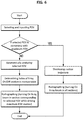
- FIG. 6 is a view showing an X-ray CT radiographing method according to an embodiment of the present invention.
- the X-ray CT radiographing method according to the present invention performs an X-ray CT radiographing sequence by using an X-ray CT radiographing apparatus including: a rotation supporter rotating based on one axis by a rotation driver, a generating unit including an X-ray generator and collimator disposed at one side of the rotation supporter to radiate an X-ray beam collimated in a predetermined width, and a sensing unit including a small width X-ray sensor disposed at a second side of the rotation supporter to face the generating unit with a subject in between and moving in a direction where the rotation supporter rotates.
- a position and a shape of a FOV are input.
- An input method may be variously performed. As described above, a way of selecting any one of FOVs corresponding to a number of anatomical sites frequently used clinically may be used.
- a geometry form of the input FOV is analyzed in an equation, and, according to the result thereof, a section where an X-ray beam is turned ON and OFF is determined in a base motion table that is defined to be suitable for performing maximum FOV radiographing.
- the base motion table includes information in which motion of the radiographing unit for obtaining a CT image of the maximum FOV, that is, motion of the rotation driver, the generating unit, and the sensing unit is preset by sections.
- a process of analyzing the selected input FOV in an equation may be replaced with reading out information that is pre-stored by analyzing the same.
- an X-ray CT radiographing sequence is performed.
- a method of turning ON and OFF the X-ray beam is as described above.
- a process of determining whether the input FOV is a concentric circle smaller than the maximum FOV may be added.
- a motion table shortened according to the same may be applied, otherwise, the input FOV does not have a shape of a concentric circle, a base motion table may be applied.
- the shortened motion table is applied, motion may be performed while an X-ray beam is turned ON in the entire section.
- Table 1 is an example of a base motion table. As shown in FIG. 2 , an example of performing an X-ray CT radiographing sequence for a maximum FOV by moving the small width X-ray sensor continuously from one end to the other end within a range of about four times of a width thereof, and rotating the rotation supporter three times while focusing an X-ray beam in association with the small width X-ray sensor is shown.
- the Table 1 shows a movement trajectory of an X-ray beam of the radiographing sequence described above which is divided into 100 sections. However, the above is only one example.
- Section index Angle of rotation supporter ( ⁇ ) Position of small width sensor X-ray beam ON/OFF 1 ⁇ 1 ( 0 degrees) P 1 ON ... ... ...
- Table 2 shows an example where a section where an X-ray beam is turned ON and OFF is determined by sections by reflecting the result of geometric analysis of the selected FOV described above in the base motion table of Table 1 above.
- Table 3 shows an example of a shortened motion table. For example, when the radiographer selects a FOV corresponding to a concentric circle smaller than the maximum FOV FC in FIG. 2 and all transmitted image frames required for reconstructing a X-ray CT image are obtained by motion in which the rotation supporter rotates 540 degrees, radiographing is performed while an X-ray beam is only turned ON in sections corresponding to section indexes from 1 to 50.
- performing motion or radiographing while an X-ray beam is turned ON means radiating an X-ray beam for obtaining an X-ray transmitted image frame corresponding to a desired section, but it is not limited that the X-ray beam continuously maintains an ON state.
- the present invention relates to an X-ray CT radiographing apparatus and a radiographing method thereof, and may be used for a medical X-ray diagnosing apparatus, more particularly, may be used in the field of a dental X-ray diagnosing apparatus.
Landscapes
- Health & Medical Sciences (AREA)
- Life Sciences & Earth Sciences (AREA)
- Engineering & Computer Science (AREA)
- Medical Informatics (AREA)
- Physics & Mathematics (AREA)
- Radiology & Medical Imaging (AREA)
- Heart & Thoracic Surgery (AREA)
- High Energy & Nuclear Physics (AREA)
- Veterinary Medicine (AREA)
- Nuclear Medicine, Radiotherapy & Molecular Imaging (AREA)
- Optics & Photonics (AREA)
- Pathology (AREA)
- Public Health (AREA)
- Biomedical Technology (AREA)
- Biophysics (AREA)
- Molecular Biology (AREA)
- Surgery (AREA)
- Animal Behavior & Ethology (AREA)
- General Health & Medical Sciences (AREA)
- Theoretical Computer Science (AREA)
- Dentistry (AREA)
- Oral & Maxillofacial Surgery (AREA)
- Pulmonology (AREA)
- General Physics & Mathematics (AREA)
- Apparatus For Radiation Diagnosis (AREA)
Claims (8)
- Röntgen-CT-Radiographie-Vorrichtung, wobei die Vorrichtung umfasst:Mittel zum Empfangen einer FOV-Eingabe (Field of View);einen Rotationsunterstützer (30), der sich auf der Grundlage einer Rotationswelle (25C) durch einen Rotationsantrieb (25) dreht;eine Erzeugungseinheit (32), die in einer ersten Seite des Rotationsträgers (30) angeordnet ist und einen Röntgengenerator (321), der Röntgenstrahlen emittiert, und einen Kollimator (322) zum Ausstrahlen eines kollimierten Röntgenstrahls enthält;einen Röntgensensor (311), der in einer zweiten Seite des Rotationsträgers (30) so angeordnet ist, dass er der Erzeugungseinheit (32) mit einem maximalen FOV (Sichtfeld) dazwischen zugewandt ist, und der einen Röntgenstrahl erfasst, der auf Teile innerhalb des Eingangs-FOV eindringt und sich in einer tangentialen Richtung einer Rotationsbahn bewegt, wenn sich der Rotationsträger dreht,wobei das Eingangs-FOV kleiner als und innerhalb des maximalen FOV ist; undeine Steuerung (60), die so konfiguriert ist, dass sie die Erzeugungseinheit (32) steuert, um die Röntgenstrahlen zu blockieren, die auf andere Teile als das Eingangs-FOV gestrahlt werden, wenn eine Röntgenaufnahme durchgeführt wird,wobei die Breite des Röntgensensors (311) kleiner als ein Vergrößerungsverhältnis * eine erste Breite w1 / 2 ist, die erste Breite w1 die Größe des maximalen Sichtfeldes in einer Richtung senkrecht zur Drehwelle (25C) ist, und das Vergrößerungsverhältnis das Verhältnis des Abstands zwischen dem Röntgengenerator (321) und dem Prüfling zu dem Abstand zwischen dem Röntgengenerator (321) und dem Röntgensensor (311) ist.
- Vorrichtung nach Anspruch 1, bei der die Steuerung (60) die Emission der Röntgenstrahlen aus dem Röntgengenerator (321) für die anderen Teile als das Eingangs-FOV stoppt.
- Vorrichtung nach Anspruch 1, bei der die Steuerung (60) die vom Röntgengenerator (321) emittierte Röntgenstrahlung für die anderen Teile als das Eingangs-FOV physikalisch blockiert, indem sie den Kollimator (322) verwendet.
- Vorrichtung nach Anspruch 1, wobei die Erzeugungseinheit (32) ferner einen Verschluss (333) aufweist, der den vom Röntgengenerator (321) emittierten Röntgenstrahl für die anderen Teile als das Eingangs-FOV physikalisch blockiert.
- Vorrichtung nach Anspruch 1, die ferner eine Bildrekonstruktionseinheit umfasst, die ein dreidimensionales Röntgenbild für mindestens einen Teil innerhalb des maximalen FOV durch Rekonstruktion eines durch den Röntgensensor (311) erfassten Ergebnisses liefert.
- Röntgen-CT-Radiographie-Verfahren, wobei das Verfahren umfasst:Empfangen einer Eingabe einer Position und einer Form eines Eingabe-FOV (Sichtfeld); undDurchführen einer Röntgen-Radiographie-Aufnahme für das Eingangs-FOV durch Drehen einer Erzeugungseinheit (32), die einen Röntgengenerator (321) enthält, und, in Verbindung damit, gleichzeitiges Drehen eines Röntgensensors (311) mit einem maximalen FOV dazwischen, wobei sich der Röntgensensor (311) in einer tangentialen Richtung der Drehtrajektorie bewegt, und Blockieren von Röntgenstrahlen, die vom Röntgengenerator (321) in Richtung anderer Teile als das Eingangs-FOV emittiert werden, wenn eine Röntgen-Radiographie-Aufnahme durchgeführt wird, wobei das Eingangs-FOV kleiner als und innerhalb des maximalen FOV ist wobei die Breite des Röntgensensors kleiner als ein Vergrößerungsverhältnis * eine erste Breite w1 / 2 ist, das Vergrößerungsverhältnis das Verhältnis des Abstands zwischen dem Röntgengenerator (321) und dem Prüfling zu dem Abstand zwischen dem Röntgengenerator (321) und dem Röntgensensor (311) ist, die erste Breite w1 die Größe des maximalen Gesichtsfelds in einer Richtung senkrecht zu einer Drehwelle (25C) ist.
- Verfahren nach Anspruch 6, bei dem bei der Röntgenaufnahme die Röntgenstrahlen im Wesentlichen blockiert werden, indem der Röntgengenerator (321) so gesteuert wird, dass er EIN/AUS geschaltet wird, oder indem der Röntgenstrahl, der in Richtung des maximalen FOV abgestrahlt wird, physikalisch blockiert wird.
- Verfahren nach Anspruch 6, weiterhin umfassend, dass nach der Röntgen-Radiographie-Aufnahme ein dreidimensionales Röntgenbild für mindestens einen Teil innerhalb des maximalen FOV durch Rekonstruktion eines durch den Röntgensensor (311) erfassten Ergebnisses bereitgestellt wird.
Applications Claiming Priority (2)
| Application Number | Priority Date | Filing Date | Title |
|---|---|---|---|
| KR1020150148910A KR101863062B1 (ko) | 2015-10-26 | 2015-10-26 | 엑스선 ct 촬영장치 및 그 촬영방법 |
| PCT/KR2016/012044 WO2017073996A1 (ko) | 2015-10-26 | 2016-10-26 | 엑스선 ct 촬영장치 및 그 촬영방법 |
Publications (3)
| Publication Number | Publication Date |
|---|---|
| EP3369376A1 EP3369376A1 (de) | 2018-09-05 |
| EP3369376A4 EP3369376A4 (de) | 2019-07-10 |
| EP3369376B1 true EP3369376B1 (de) | 2021-01-27 |
Family
ID=58631718
Family Applications (1)
| Application Number | Title | Priority Date | Filing Date |
|---|---|---|---|
| EP16860179.7A Active EP3369376B1 (de) | 2015-10-26 | 2016-10-26 | Röntgen-ct-abtastvorrichtung und abtastverfahren dafür |
Country Status (5)
| Country | Link |
|---|---|
| US (1) | US10709405B2 (de) |
| EP (1) | EP3369376B1 (de) |
| KR (1) | KR101863062B1 (de) |
| CN (1) | CN108366768B (de) |
| WO (1) | WO2017073996A1 (de) |
Families Citing this family (6)
| Publication number | Priority date | Publication date | Assignee | Title |
|---|---|---|---|---|
| US10973473B2 (en) * | 2017-06-27 | 2021-04-13 | Canon Medical Systems Corporation | X-ray diagnostic apparatus |
| US10799193B2 (en) * | 2019-02-12 | 2020-10-13 | Malcova LLC | Method and apparatus for anatomically-specified conformation computed tomography |
| EP3756617B1 (de) * | 2019-06-27 | 2024-05-22 | DENTSPLY SIRONA Inc. | Verfahren zur erfassung von mindestens einem anatomischen merkmal eines patienten |
| US11622735B1 (en) | 2022-10-20 | 2023-04-11 | MALCOVA, Inc. | Plural-plane narrow-beam computed tomography |
| KR102755370B1 (ko) * | 2022-11-17 | 2025-01-21 | 주식회사 우리엔 | 엑스선 영상 촬영 장치 |
| US12181424B1 (en) | 2024-07-24 | 2024-12-31 | MALCOVA, Inc. | Method and apparatus of stationary-source nonplanar-trajectory narrow-beam computed tomography |
Family Cites Families (22)
| Publication number | Priority date | Publication date | Assignee | Title |
|---|---|---|---|---|
| EP2915488B1 (de) * | 2002-03-19 | 2019-06-05 | Medtronic Navigation, Inc. | Computertomografie mit einem detektor, der der bewegung einer drehbaren röntgenquelle folgt |
| DE102004020861B4 (de) | 2004-04-28 | 2009-10-01 | Siemens Ag | Verfahren zur Rekonstruktion von Projektionsdatensätzen bei Dosis-reduzierter abschnittsweiser spiralförmiger Abtastung in der Computertomographie |
| US7570732B2 (en) | 2005-11-09 | 2009-08-04 | Dexela Limited | Methods and apparatus for obtaining low-dose imaging |
| US20070242868A1 (en) | 2005-11-09 | 2007-10-18 | Dexela Limited | Methods and apparatus for displaying images |
| US7545907B2 (en) | 2005-11-09 | 2009-06-09 | Dexela Limited | Methods and apparatus for obtaining low-dose imaging |
| WO2008069367A1 (en) | 2006-12-04 | 2008-06-12 | E-Woo Technology Co., Ltd | A x-ray photographing apparatus comprising cephalo sensors |
| KR20090130719A (ko) | 2008-06-16 | 2009-12-24 | 주식회사바텍 | 토모그래피 영상획득방법 |
| KR101033249B1 (ko) | 2009-04-17 | 2011-05-06 | (주)포인트닉스 | 치과용 파노라마 및 씨티 겸용 엑스선 촬영장치 |
| EP2446822B1 (de) * | 2009-06-25 | 2019-05-08 | The Yoshida Dental Mfg. Co., Ltd. | Röntgenphotographievorrichtung |
| FI20110106L (fi) | 2011-03-21 | 2012-04-13 | Planmeca Oy | Hammaslääketieteellinen kuvauslaitteisto |
| KR101340456B1 (ko) | 2011-06-30 | 2013-12-11 | 주식회사 휴먼레이 | 다중 센서를 갖는 맘모그래피용 디텍터 및 3차원 영상 획득이 가능한 맘모그래피 장치 |
| JP5864403B2 (ja) * | 2011-11-30 | 2016-02-17 | 株式会社モリタ製作所 | X線ct撮影装置 |
| KR101384601B1 (ko) * | 2011-12-22 | 2014-04-15 | (주)제노레이 | 디지털 엑스선 유방암 진단장치 및 진단 방법 |
| US11534122B2 (en) | 2012-09-20 | 2022-12-27 | Virginia Tech Intellectual Properties, Inc. | Stationary source computed tomography and CT-MRI systems |
| JP6125200B2 (ja) * | 2012-11-05 | 2017-05-10 | 株式会社吉田製作所 | X線撮影装置 |
| US8798230B2 (en) * | 2012-11-19 | 2014-08-05 | Samsung Electronics Co., Ltd. | Radiation imaging apparatus, computed tomography apparatus, and radiation imaging method |
| EP2757687A1 (de) * | 2013-01-21 | 2014-07-23 | Dialog Semiconductor GmbH | Synchronisierungsschaltung mit geringer Latenz |
| US10004468B2 (en) * | 2013-08-20 | 2018-06-26 | Vatech Co., Ltd. | X-ray imaging device and X-ray imaging method |
| KR20150024706A (ko) | 2013-08-27 | 2015-03-09 | 주식회사바텍 | Ct 촬영 장치 |
| WO2015030472A1 (ko) | 2013-08-27 | 2015-03-05 | 주식회사바텍 | 씨티 촬영 장치 및 씨티 촬영 방법 |
| KR20150062521A (ko) | 2013-11-29 | 2015-06-08 | 주식회사바텍 | Ct 촬영 장치 |
| KR102233319B1 (ko) * | 2014-01-20 | 2021-03-29 | 삼성전자주식회사 | 관심 영역 추적 방법, 방사선 촬영 장치, 방사선 촬영 장치의 제어 방법 및 방사선 촬영 방법 |
-
2015
- 2015-10-26 KR KR1020150148910A patent/KR101863062B1/ko active Active
-
2016
- 2016-10-26 CN CN201680071425.9A patent/CN108366768B/zh active Active
- 2016-10-26 US US15/771,390 patent/US10709405B2/en active Active
- 2016-10-26 EP EP16860179.7A patent/EP3369376B1/de active Active
- 2016-10-26 WO PCT/KR2016/012044 patent/WO2017073996A1/ko not_active Ceased
Non-Patent Citations (1)
| Title |
|---|
| None * |
Also Published As
| Publication number | Publication date |
|---|---|
| US10709405B2 (en) | 2020-07-14 |
| CN108366768B (zh) | 2022-05-10 |
| KR101863062B1 (ko) | 2018-05-31 |
| EP3369376A4 (de) | 2019-07-10 |
| WO2017073996A1 (ko) | 2017-05-04 |
| EP3369376A1 (de) | 2018-09-05 |
| CN108366768A (zh) | 2018-08-03 |
| KR20170048042A (ko) | 2017-05-08 |
| US20180333127A1 (en) | 2018-11-22 |
Similar Documents
| Publication | Publication Date | Title |
|---|---|---|
| EP3369376B1 (de) | Röntgen-ct-abtastvorrichtung und abtastverfahren dafür | |
| EP3369377B1 (de) | Röntgenbilderfassungsvorrichtung | |
| EP4312783B1 (de) | Progressive scans mit mehrfach gepulstem tomosynthesebildgebungssystem mit röntgenquelle in bewegung | |
| US7330529B2 (en) | Stationary tomographic mammography system | |
| EP2896366B1 (de) | Radiografievorrichtungen und Verfahren zur Steuerung von Radiografievorrichtungen | |
| US9014341B2 (en) | CT collimator and CT system including the CT collimator | |
| US8494117B2 (en) | Radiation therapy device | |
| US7342993B2 (en) | System for dynamic low dose x-ray imaging | |
| JP5269358B2 (ja) | X線ct装置 | |
| EP3533396A1 (de) | Radiografische vorrichtung und radiografisches verfahren zur verwendung davon | |
| US8506163B2 (en) | X-ray CT apparatus and control method of X-ray CT apparatus | |
| CN101902968A (zh) | 同步介入性扫描器 | |
| JP2011507579A (ja) | 患者の露出を減らすためのコーンビーム・コンピュータ断層撮影におけるダイナミック・コリメーション | |
| KR101740358B1 (ko) | 엑스선 영상 촬영장치 및 엑스선 영상 촬영방법 | |
| JP2006311882A (ja) | 放射線ct装置 | |
| EP3923813B1 (de) | Verfahren und vorrichtung für die anatomisch-spezifizierte computertomografie | |
| EP3142557B1 (de) | Mehrfachbrennfleckabbildungssystem | |
| EP3603517A1 (de) | Radiografische vorrichtung und radiografisches verfahren zur verwendung davon | |
| JP7657854B2 (ja) | 2つのキャリッジを有する統合フィルタアセンブリ用のシステム及び方法 | |
| US7839967B2 (en) | Electron computer tomography method and electron computer tomograph | |
| US20250331790A1 (en) | Methods and systems for an integrated filter system with two carriages | |
| KR102022454B1 (ko) | 듀얼 에너지 방식 컴퓨터 단층촬영장치의 x-레이 필터 제어기구 | |
| JP2015139534A (ja) | X線ct装置及び投光器 |
Legal Events
| Date | Code | Title | Description |
|---|---|---|---|
| STAA | Information on the status of an ep patent application or granted ep patent |
Free format text: STATUS: THE INTERNATIONAL PUBLICATION HAS BEEN MADE |
|
| PUAI | Public reference made under article 153(3) epc to a published international application that has entered the european phase |
Free format text: ORIGINAL CODE: 0009012 |
|
| STAA | Information on the status of an ep patent application or granted ep patent |
Free format text: STATUS: REQUEST FOR EXAMINATION WAS MADE |
|
| 17P | Request for examination filed |
Effective date: 20180509 |
|
| AK | Designated contracting states |
Kind code of ref document: A1 Designated state(s): AL AT BE BG CH CY CZ DE DK EE ES FI FR GB GR HR HU IE IS IT LI LT LU LV MC MK MT NL NO PL PT RO RS SE SI SK SM TR |
|
| AX | Request for extension of the european patent |
Extension state: BA ME |
|
| DAV | Request for validation of the european patent (deleted) | ||
| DAX | Request for extension of the european patent (deleted) | ||
| A4 | Supplementary search report drawn up and despatched |
Effective date: 20190611 |
|
| RIC1 | Information provided on ipc code assigned before grant |
Ipc: A61B 6/14 20060101ALI20190604BHEP Ipc: A61B 6/03 20060101ALI20190604BHEP Ipc: A61B 6/10 20060101ALI20190604BHEP Ipc: A61B 6/00 20060101AFI20190604BHEP Ipc: A61B 6/08 20060101ALI20190604BHEP |
|
| GRAP | Despatch of communication of intention to grant a patent |
Free format text: ORIGINAL CODE: EPIDOSNIGR1 |
|
| STAA | Information on the status of an ep patent application or granted ep patent |
Free format text: STATUS: GRANT OF PATENT IS INTENDED |
|
| INTG | Intention to grant announced |
Effective date: 20201027 |
|
| GRAS | Grant fee paid |
Free format text: ORIGINAL CODE: EPIDOSNIGR3 |
|
| GRAA | (expected) grant |
Free format text: ORIGINAL CODE: 0009210 |
|
| STAA | Information on the status of an ep patent application or granted ep patent |
Free format text: STATUS: THE PATENT HAS BEEN GRANTED |
|
| AK | Designated contracting states |
Kind code of ref document: B1 Designated state(s): AL AT BE BG CH CY CZ DE DK EE ES FI FR GB GR HR HU IE IS IT LI LT LU LV MC MK MT NL NO PL PT RO RS SE SI SK SM TR |
|
| REG | Reference to a national code |
Ref country code: GB Ref legal event code: FG4D |
|
| REG | Reference to a national code |
Ref country code: CH Ref legal event code: EP |
|
| REG | Reference to a national code |
Ref country code: AT Ref legal event code: REF Ref document number: 1357631 Country of ref document: AT Kind code of ref document: T Effective date: 20210215 |
|
| REG | Reference to a national code |
Ref country code: IE Ref legal event code: FG4D |
|
| REG | Reference to a national code |
Ref country code: DE Ref legal event code: R096 Ref document number: 602016052213 Country of ref document: DE |
|
| REG | Reference to a national code |
Ref country code: NL Ref legal event code: MP Effective date: 20210127 |
|
| REG | Reference to a national code |
Ref country code: LT Ref legal event code: MG9D |
|
| REG | Reference to a national code |
Ref country code: AT Ref legal event code: MK05 Ref document number: 1357631 Country of ref document: AT Kind code of ref document: T Effective date: 20210127 |
|
| PG25 | Lapsed in a contracting state [announced via postgrant information from national office to epo] |
Ref country code: FI Free format text: LAPSE BECAUSE OF FAILURE TO SUBMIT A TRANSLATION OF THE DESCRIPTION OR TO PAY THE FEE WITHIN THE PRESCRIBED TIME-LIMIT Effective date: 20210127 Ref country code: GR Free format text: LAPSE BECAUSE OF FAILURE TO SUBMIT A TRANSLATION OF THE DESCRIPTION OR TO PAY THE FEE WITHIN THE PRESCRIBED TIME-LIMIT Effective date: 20210428 Ref country code: HR Free format text: LAPSE BECAUSE OF FAILURE TO SUBMIT A TRANSLATION OF THE DESCRIPTION OR TO PAY THE FEE WITHIN THE PRESCRIBED TIME-LIMIT Effective date: 20210127 Ref country code: NO Free format text: LAPSE BECAUSE OF FAILURE TO SUBMIT A TRANSLATION OF THE DESCRIPTION OR TO PAY THE FEE WITHIN THE PRESCRIBED TIME-LIMIT Effective date: 20210427 Ref country code: PT Free format text: LAPSE BECAUSE OF FAILURE TO SUBMIT A TRANSLATION OF THE DESCRIPTION OR TO PAY THE FEE WITHIN THE PRESCRIBED TIME-LIMIT Effective date: 20210527 Ref country code: LT Free format text: LAPSE BECAUSE OF FAILURE TO SUBMIT A TRANSLATION OF THE DESCRIPTION OR TO PAY THE FEE WITHIN THE PRESCRIBED TIME-LIMIT Effective date: 20210127 Ref country code: BG Free format text: LAPSE BECAUSE OF FAILURE TO SUBMIT A TRANSLATION OF THE DESCRIPTION OR TO PAY THE FEE WITHIN THE PRESCRIBED TIME-LIMIT Effective date: 20210427 |
|
| PG25 | Lapsed in a contracting state [announced via postgrant information from national office to epo] |
Ref country code: SE Free format text: LAPSE BECAUSE OF FAILURE TO SUBMIT A TRANSLATION OF THE DESCRIPTION OR TO PAY THE FEE WITHIN THE PRESCRIBED TIME-LIMIT Effective date: 20210127 Ref country code: AT Free format text: LAPSE BECAUSE OF FAILURE TO SUBMIT A TRANSLATION OF THE DESCRIPTION OR TO PAY THE FEE WITHIN THE PRESCRIBED TIME-LIMIT Effective date: 20210127 Ref country code: RS Free format text: LAPSE BECAUSE OF FAILURE TO SUBMIT A TRANSLATION OF THE DESCRIPTION OR TO PAY THE FEE WITHIN THE PRESCRIBED TIME-LIMIT Effective date: 20210127 Ref country code: LV Free format text: LAPSE BECAUSE OF FAILURE TO SUBMIT A TRANSLATION OF THE DESCRIPTION OR TO PAY THE FEE WITHIN THE PRESCRIBED TIME-LIMIT Effective date: 20210127 Ref country code: PL Free format text: LAPSE BECAUSE OF FAILURE TO SUBMIT A TRANSLATION OF THE DESCRIPTION OR TO PAY THE FEE WITHIN THE PRESCRIBED TIME-LIMIT Effective date: 20210127 |
|
| PG25 | Lapsed in a contracting state [announced via postgrant information from national office to epo] |
Ref country code: IS Free format text: LAPSE BECAUSE OF FAILURE TO SUBMIT A TRANSLATION OF THE DESCRIPTION OR TO PAY THE FEE WITHIN THE PRESCRIBED TIME-LIMIT Effective date: 20210527 |
|
| REG | Reference to a national code |
Ref country code: DE Ref legal event code: R097 Ref document number: 602016052213 Country of ref document: DE |
|
| PG25 | Lapsed in a contracting state [announced via postgrant information from national office to epo] |
Ref country code: SM Free format text: LAPSE BECAUSE OF FAILURE TO SUBMIT A TRANSLATION OF THE DESCRIPTION OR TO PAY THE FEE WITHIN THE PRESCRIBED TIME-LIMIT Effective date: 20210127 Ref country code: EE Free format text: LAPSE BECAUSE OF FAILURE TO SUBMIT A TRANSLATION OF THE DESCRIPTION OR TO PAY THE FEE WITHIN THE PRESCRIBED TIME-LIMIT Effective date: 20210127 Ref country code: CZ Free format text: LAPSE BECAUSE OF FAILURE TO SUBMIT A TRANSLATION OF THE DESCRIPTION OR TO PAY THE FEE WITHIN THE PRESCRIBED TIME-LIMIT Effective date: 20210127 |
|
| PG25 | Lapsed in a contracting state [announced via postgrant information from national office to epo] |
Ref country code: SK Free format text: LAPSE BECAUSE OF FAILURE TO SUBMIT A TRANSLATION OF THE DESCRIPTION OR TO PAY THE FEE WITHIN THE PRESCRIBED TIME-LIMIT Effective date: 20210127 Ref country code: RO Free format text: LAPSE BECAUSE OF FAILURE TO SUBMIT A TRANSLATION OF THE DESCRIPTION OR TO PAY THE FEE WITHIN THE PRESCRIBED TIME-LIMIT Effective date: 20210127 Ref country code: DK Free format text: LAPSE BECAUSE OF FAILURE TO SUBMIT A TRANSLATION OF THE DESCRIPTION OR TO PAY THE FEE WITHIN THE PRESCRIBED TIME-LIMIT Effective date: 20210127 |
|
| PLBE | No opposition filed within time limit |
Free format text: ORIGINAL CODE: 0009261 |
|
| STAA | Information on the status of an ep patent application or granted ep patent |
Free format text: STATUS: NO OPPOSITION FILED WITHIN TIME LIMIT |
|
| 26N | No opposition filed |
Effective date: 20211028 |
|
| PG25 | Lapsed in a contracting state [announced via postgrant information from national office to epo] |
Ref country code: ES Free format text: LAPSE BECAUSE OF FAILURE TO SUBMIT A TRANSLATION OF THE DESCRIPTION OR TO PAY THE FEE WITHIN THE PRESCRIBED TIME-LIMIT Effective date: 20210127 Ref country code: AL Free format text: LAPSE BECAUSE OF FAILURE TO SUBMIT A TRANSLATION OF THE DESCRIPTION OR TO PAY THE FEE WITHIN THE PRESCRIBED TIME-LIMIT Effective date: 20210127 |
|
| PG25 | Lapsed in a contracting state [announced via postgrant information from national office to epo] |
Ref country code: SI Free format text: LAPSE BECAUSE OF FAILURE TO SUBMIT A TRANSLATION OF THE DESCRIPTION OR TO PAY THE FEE WITHIN THE PRESCRIBED TIME-LIMIT Effective date: 20210127 |
|
| PG25 | Lapsed in a contracting state [announced via postgrant information from national office to epo] |
Ref country code: IT Free format text: LAPSE BECAUSE OF FAILURE TO SUBMIT A TRANSLATION OF THE DESCRIPTION OR TO PAY THE FEE WITHIN THE PRESCRIBED TIME-LIMIT Effective date: 20210127 |
|
| REG | Reference to a national code |
Ref country code: CH Ref legal event code: PL |
|
| PG25 | Lapsed in a contracting state [announced via postgrant information from national office to epo] |
Ref country code: IS Free format text: LAPSE BECAUSE OF FAILURE TO SUBMIT A TRANSLATION OF THE DESCRIPTION OR TO PAY THE FEE WITHIN THE PRESCRIBED TIME-LIMIT Effective date: 20210527 |
|
| REG | Reference to a national code |
Ref country code: BE Ref legal event code: MM Effective date: 20211031 |
|
| PG25 | Lapsed in a contracting state [announced via postgrant information from national office to epo] |
Ref country code: MC Free format text: LAPSE BECAUSE OF FAILURE TO SUBMIT A TRANSLATION OF THE DESCRIPTION OR TO PAY THE FEE WITHIN THE PRESCRIBED TIME-LIMIT Effective date: 20210127 |
|
| PG25 | Lapsed in a contracting state [announced via postgrant information from national office to epo] |
Ref country code: LU Free format text: LAPSE BECAUSE OF NON-PAYMENT OF DUE FEES Effective date: 20211026 Ref country code: BE Free format text: LAPSE BECAUSE OF NON-PAYMENT OF DUE FEES Effective date: 20211031 |
|
| PG25 | Lapsed in a contracting state [announced via postgrant information from national office to epo] |
Ref country code: LI Free format text: LAPSE BECAUSE OF NON-PAYMENT OF DUE FEES Effective date: 20211031 Ref country code: CH Free format text: LAPSE BECAUSE OF NON-PAYMENT OF DUE FEES Effective date: 20211031 |
|
| PG25 | Lapsed in a contracting state [announced via postgrant information from national office to epo] |
Ref country code: IE Free format text: LAPSE BECAUSE OF NON-PAYMENT OF DUE FEES Effective date: 20211026 |
|
| PG25 | Lapsed in a contracting state [announced via postgrant information from national office to epo] |
Ref country code: HU Free format text: LAPSE BECAUSE OF FAILURE TO SUBMIT A TRANSLATION OF THE DESCRIPTION OR TO PAY THE FEE WITHIN THE PRESCRIBED TIME-LIMIT; INVALID AB INITIO Effective date: 20161026 |
|
| PG25 | Lapsed in a contracting state [announced via postgrant information from national office to epo] |
Ref country code: NL Free format text: LAPSE BECAUSE OF NON-PAYMENT OF DUE FEES Effective date: 20210127 Ref country code: CY Free format text: LAPSE BECAUSE OF FAILURE TO SUBMIT A TRANSLATION OF THE DESCRIPTION OR TO PAY THE FEE WITHIN THE PRESCRIBED TIME-LIMIT Effective date: 20210127 |
|
| P01 | Opt-out of the competence of the unified patent court (upc) registered |
Effective date: 20230526 |
|
| PG25 | Lapsed in a contracting state [announced via postgrant information from national office to epo] |
Ref country code: MK Free format text: LAPSE BECAUSE OF FAILURE TO SUBMIT A TRANSLATION OF THE DESCRIPTION OR TO PAY THE FEE WITHIN THE PRESCRIBED TIME-LIMIT Effective date: 20210127 |
|
| PG25 | Lapsed in a contracting state [announced via postgrant information from national office to epo] |
Ref country code: MT Free format text: LAPSE BECAUSE OF FAILURE TO SUBMIT A TRANSLATION OF THE DESCRIPTION OR TO PAY THE FEE WITHIN THE PRESCRIBED TIME-LIMIT Effective date: 20210127 |
|
| PG25 | Lapsed in a contracting state [announced via postgrant information from national office to epo] |
Ref country code: TR Free format text: LAPSE BECAUSE OF FAILURE TO SUBMIT A TRANSLATION OF THE DESCRIPTION OR TO PAY THE FEE WITHIN THE PRESCRIBED TIME-LIMIT Effective date: 20210127 |
|
| PGFP | Annual fee paid to national office [announced via postgrant information from national office to epo] |
Ref country code: DE Payment date: 20251002 Year of fee payment: 10 |
|
| PGFP | Annual fee paid to national office [announced via postgrant information from national office to epo] |
Ref country code: GB Payment date: 20251001 Year of fee payment: 10 |
|
| PGFP | Annual fee paid to national office [announced via postgrant information from national office to epo] |
Ref country code: FR Payment date: 20251001 Year of fee payment: 10 |