EP3369385A2 - Angetriebene chirurgische vorrichtungen mit gewebeerfassungsfunktion - Google Patents
Angetriebene chirurgische vorrichtungen mit gewebeerfassungsfunktion Download PDFInfo
- Publication number
- EP3369385A2 EP3369385A2 EP18159314.6A EP18159314A EP3369385A2 EP 3369385 A2 EP3369385 A2 EP 3369385A2 EP 18159314 A EP18159314 A EP 18159314A EP 3369385 A2 EP3369385 A2 EP 3369385A2
- Authority
- EP
- European Patent Office
- Prior art keywords
- assembly
- end effector
- sensor
- anvil
- sensor data
- Prior art date
- Legal status (The legal status is an assumption and is not a legal conclusion. Google has not performed a legal analysis and makes no representation as to the accuracy of the status listed.)
- Granted
Links
Images


Classifications
-
- A—HUMAN NECESSITIES
- A61—MEDICAL OR VETERINARY SCIENCE; HYGIENE
- A61B—DIAGNOSIS; SURGERY; IDENTIFICATION
- A61B17/00—Surgical instruments, devices or methods
- A61B17/068—Surgical staplers, e.g. containing multiple staples or clamps
- A61B17/0682—Surgical staplers, e.g. containing multiple staples or clamps for applying U-shaped staples or clamps, e.g. without a forming anvil
-
- A—HUMAN NECESSITIES
- A61—MEDICAL OR VETERINARY SCIENCE; HYGIENE
- A61B—DIAGNOSIS; SURGERY; IDENTIFICATION
- A61B17/00—Surgical instruments, devices or methods
- A61B17/068—Surgical staplers, e.g. containing multiple staples or clamps
- A61B17/072—Surgical staplers, e.g. containing multiple staples or clamps for applying a row of staples in a single action, e.g. the staples being applied simultaneously
- A61B17/07207—Surgical staplers, e.g. containing multiple staples or clamps for applying a row of staples in a single action, e.g. the staples being applied simultaneously the staples being applied sequentially
-
- A—HUMAN NECESSITIES
- A61—MEDICAL OR VETERINARY SCIENCE; HYGIENE
- A61B—DIAGNOSIS; SURGERY; IDENTIFICATION
- A61B17/00—Surgical instruments, devices or methods
- A61B17/04—Surgical instruments, devices or methods for suturing wounds; Holders or packages for needles or suture materials
- A61B17/0483—Hand-held instruments for holding sutures
-
- A—HUMAN NECESSITIES
- A61—MEDICAL OR VETERINARY SCIENCE; HYGIENE
- A61B—DIAGNOSIS; SURGERY; IDENTIFICATION
- A61B17/00—Surgical instruments, devices or methods
- A61B2017/00017—Electrical control of surgical instruments
-
- A—HUMAN NECESSITIES
- A61—MEDICAL OR VETERINARY SCIENCE; HYGIENE
- A61B—DIAGNOSIS; SURGERY; IDENTIFICATION
- A61B17/00—Surgical instruments, devices or methods
- A61B2017/00017—Electrical control of surgical instruments
- A61B2017/00022—Sensing or detecting at the treatment site
-
- A—HUMAN NECESSITIES
- A61—MEDICAL OR VETERINARY SCIENCE; HYGIENE
- A61B—DIAGNOSIS; SURGERY; IDENTIFICATION
- A61B17/00—Surgical instruments, devices or methods
- A61B2017/00017—Electrical control of surgical instruments
- A61B2017/00022—Sensing or detecting at the treatment site
- A61B2017/00026—Conductivity or impedance, e.g. of tissue
- A61B2017/00035—Conductivity or impedance, e.g. of tissue pH
-
- A—HUMAN NECESSITIES
- A61—MEDICAL OR VETERINARY SCIENCE; HYGIENE
- A61B—DIAGNOSIS; SURGERY; IDENTIFICATION
- A61B17/00—Surgical instruments, devices or methods
- A61B2017/00017—Electrical control of surgical instruments
- A61B2017/00022—Sensing or detecting at the treatment site
- A61B2017/00084—Temperature
-
- A—HUMAN NECESSITIES
- A61—MEDICAL OR VETERINARY SCIENCE; HYGIENE
- A61B—DIAGNOSIS; SURGERY; IDENTIFICATION
- A61B17/00—Surgical instruments, devices or methods
- A61B2017/00367—Details of actuation of instruments, e.g. relations between pushing buttons, or the like, and activation of the tool, working tip, or the like
- A61B2017/00398—Details of actuation of instruments, e.g. relations between pushing buttons, or the like, and activation of the tool, working tip, or the like using powered actuators, e.g. stepper motors, solenoids
-
- A—HUMAN NECESSITIES
- A61—MEDICAL OR VETERINARY SCIENCE; HYGIENE
- A61B—DIAGNOSIS; SURGERY; IDENTIFICATION
- A61B17/00—Surgical instruments, devices or methods
- A61B2017/0046—Surgical instruments, devices or methods with a releasable handle; with handle and operating part separable
-
- A—HUMAN NECESSITIES
- A61—MEDICAL OR VETERINARY SCIENCE; HYGIENE
- A61B—DIAGNOSIS; SURGERY; IDENTIFICATION
- A61B17/00—Surgical instruments, devices or methods
- A61B2017/0046—Surgical instruments, devices or methods with a releasable handle; with handle and operating part separable
- A61B2017/00473—Distal part, e.g. tip or head
-
- A—HUMAN NECESSITIES
- A61—MEDICAL OR VETERINARY SCIENCE; HYGIENE
- A61B—DIAGNOSIS; SURGERY; IDENTIFICATION
- A61B17/00—Surgical instruments, devices or methods
- A61B2017/00477—Coupling
-
- A—HUMAN NECESSITIES
- A61—MEDICAL OR VETERINARY SCIENCE; HYGIENE
- A61B—DIAGNOSIS; SURGERY; IDENTIFICATION
- A61B17/00—Surgical instruments, devices or methods
- A61B2017/00681—Aspects not otherwise provided for
- A61B2017/00734—Aspects not otherwise provided for battery operated
-
- A—HUMAN NECESSITIES
- A61—MEDICAL OR VETERINARY SCIENCE; HYGIENE
- A61B—DIAGNOSIS; SURGERY; IDENTIFICATION
- A61B17/00—Surgical instruments, devices or methods
- A61B17/068—Surgical staplers, e.g. containing multiple staples or clamps
- A61B17/072—Surgical staplers, e.g. containing multiple staples or clamps for applying a row of staples in a single action, e.g. the staples being applied simultaneously
- A61B2017/07214—Stapler heads
- A61B2017/07257—Stapler heads characterised by its anvil
-
- A—HUMAN NECESSITIES
- A61—MEDICAL OR VETERINARY SCIENCE; HYGIENE
- A61B—DIAGNOSIS; SURGERY; IDENTIFICATION
- A61B17/00—Surgical instruments, devices or methods
- A61B17/068—Surgical staplers, e.g. containing multiple staples or clamps
- A61B17/072—Surgical staplers, e.g. containing multiple staples or clamps for applying a row of staples in a single action, e.g. the staples being applied simultaneously
- A61B2017/07214—Stapler heads
- A61B2017/07271—Stapler heads characterised by its cartridge
-
- A—HUMAN NECESSITIES
- A61—MEDICAL OR VETERINARY SCIENCE; HYGIENE
- A61B—DIAGNOSIS; SURGERY; IDENTIFICATION
- A61B17/00—Surgical instruments, devices or methods
- A61B17/068—Surgical staplers, e.g. containing multiple staples or clamps
- A61B17/072—Surgical staplers, e.g. containing multiple staples or clamps for applying a row of staples in a single action, e.g. the staples being applied simultaneously
- A61B2017/07214—Stapler heads
- A61B2017/07285—Stapler heads characterised by its cutter
-
- A—HUMAN NECESSITIES
- A61—MEDICAL OR VETERINARY SCIENCE; HYGIENE
- A61B—DIAGNOSIS; SURGERY; IDENTIFICATION
- A61B90/00—Instruments, implements or accessories specially adapted for surgery or diagnosis and not covered by any of the groups A61B1/00 - A61B50/00, e.g. for luxation treatment or for protecting wound edges
- A61B90/06—Measuring instruments not otherwise provided for
- A61B2090/064—Measuring instruments not otherwise provided for for measuring force, pressure or mechanical tension
- A61B2090/065—Measuring instruments not otherwise provided for for measuring force, pressure or mechanical tension for measuring contact or contact pressure
Definitions
- the present disclosure relates generally to surgical devices. More particularly, the present disclosure relates to powered handheld electromechanical instruments including sensors for in vivo monitoring of tissue behavior in real-time during surgical procedures.
- a linear clamping, cutting and stapling device Such a device may be employed in a surgical procedure to resect a cancerous or anomalous tissue from a gastro-intestinal tract.
- Conventional linear clamping, cutting and stapling instruments include a pistol grip-styled structure having an elongated shaft and distal portion. The distal portion includes a pair of scissors-styled gripping elements, which clamp tissue, such as the open ends of the colon, closed.
- one of the two scissors-styled gripping elements such as an anvil portion, moves or pivots relative to the overall structure, whereas the other gripping element remains fixed relative to the overall structure.
- the actuation of this scissoring device (the pivoting of the anvil portion) is controlled by a grip trigger maintained in the handle.
- the distal portion also includes a stapling mechanism.
- the fixed gripping element of the scissoring mechanism includes a staple cartridge receiving region and a mechanism for driving the staples up through the clamped end of the tissue against the anvil portion, thereby sealing the previously opened end.
- the scissoring elements may be integrally formed with the shaft or may be detachable such that various scissoring and stapling elements may be interchangeable.
- the surgical devices include a powered handle assembly, which is reusable, and a disposable end effector or the like that is selectively connected to the powered handle assembly prior to use and then disconnected from the end effector following use in order to be disposed of, or in some instances sterilized for re-use.
- powered stapling devices use current sensors to detect electrical current draw from a motor of the device, or a strain gauge along a drive assembly of the device, as an indicator of the forces required to compress tissue, form staples, and transect the tissue. Data collected from these sensors are used to control the speed of firing, which has been shown to improve staple formation by slowing the stapler speed and lowering the firing force. The data may also be used in other aspects of the stapling process, such as detecting end stop and emergency stopping to prevent damage to the end effector.
- These powered stapling devices are limited in obtaining data regarding the in vivo mechanical behavior (e.g., the mechanical force, stress, and strain) of the tissue. Without this data, it is difficult to prevent acute trauma due to stress thresholds that were exceeded in the tissue while performing a stapling procedure.
- the surgical devices of the present disclosure include sensors for in vivo monitoring of tissue mechanics in real time to provide a more intelligent surgical device to improve stapling performance and minimize negative acute trauma to the tissue.
- a surgical device in accordance with aspects of the present disclosure includes an end effector and a handle assembly.
- the end effector includes a body portion and a tool assembly disposed at a distal end of the body portion.
- the tool assembly is insertable into a target surgical site and includes an anvil assembly, a cartridge assembly, and a sensor disposed on an outer surface of the anvil assembly or the cartridge assembly for measuring a mechanical property of at least one of the anvil assembly or the cartridge assembly.
- the handle assembly is operably coupled to the end effector and is operable to approximate the anvil assembly and the cartridge assembly onto target tissue.
- the handle assembly includes a power-pack including a controller circuit board configured to receive sensor data of the sensor corresponding to the mechanical property of at least one of the anvil assembly or the cartridge assembly, at least during an approximation of the anvil assembly and the cartridge assembly onto the target tissue.
- the controller circuit board processes the sensor data into a property of the target tissue.
- the controller circuit board then controls a function of the end effector in response to the processed sensor data.
- the sensor may be a pressure sensor, and in some aspects, the sensor is a strain gauge.
- the sensor may be one of a plurality of sensors disposed on the outer surface of the anvil assembly or the cartridge assembly. In some aspects, at least two of the plurality of sensors measure the same preselected mechanical property. In certain aspects, the preselected mechanical property is tissue stress.
- the controller circuit board of the power-pack of the handle assembly may be electrically coupled to at least one motor and configured to control each motor.
- the at least one motor may be configured to effect the function of the end effector.
- the end effector includes a microcontroller coupled to a memory.
- the microcontroller is electrically coupled to the sensor and configured to receive and process the sensor data from the sensor, and the memory is configured to store the sensor data.
- the power-pack is configured to detect that the end effector is operably engaged with the handle assembly and to access the sensor data stored in the memory of the end effector.
- the surgical device may include an adapter assembly interconnecting the handle assembly and the end effector.
- the adapter assembly includes an electrical assembly including a circuit board electrically connected to electrical contacts disposed in a distal portion of the adapter assembly. The electrical contacts of the adapter assembly are configured to engage electrical contacts of the end effector which are electrically connected to the memory of the end effector.
- the adapter assembly includes a plurality of electrical contact blades supported on the circuit board for electrical connection with a pass-through connector of the handle assembly which is electrically connected to the controller circuit board of the handle assembly.
- a method of performing a surgical stapling procedure with the surgical device includes inserting the tool assembly of the end effector of the surgical device into a target surgical site; clamping a target tissue between tissue contacting surfaces of the anvil and cartridge assemblies; and waiting for an indication from the surgical device that the property of the tissue is at a value within an acceptable range of values, based on the processed sensor data, to fire staples into the target tissue.
- An end effector for a surgical device in accordance with aspects of the present disclosure includes a body portion and a tool assembly disposed at a distal end of the body portion.
- the tool assembly includes an anvil assembly, a cartridge assembly pivotally coupled to the anvil assembly, a sensor disposed on an outer surface of the anvil assembly or the cartridge assembly, a microcontroller disposed within the body portion, and a memory disposed within the body portion.
- the sensor is configured to measure a mechanical property of at least one of the anvil assembly or the cartridge assembly, at least during an approximation of the anvil assembly and the cartridge assembly onto the target tissue.
- the microcontroller is electrically coupled to the sensor and is configured to receive sensor data of the sensor corresponding to the mechanical property of at least one of the anvil assembly or the cartridge assembly and processes the sensor data into a property of the target tissue, and wherein the microcontroller controls a function of the tool assembly in response to the processed sensor data.
- the memory is coupled to the microcontroller and configured to store at least one of the sensor data or the processed sensor data.
- the sensor may be a pressure sensor, and in some aspects, the sensor is a strain gauge.
- the sensor may be one of a plurality of sensors disposed on the outer surface of the anvil assembly or the cartridge assembly. In some aspects, at least two of the plurality of sensors measure the same preselected mechanical property. In certain aspects, the preselected mechanical property is tissue stress.
- the microcontroller may continuously monitor the sensor to collect the sensor data.
- proximal refers to a portion of a device, or component thereof, that is closer to a user
- distal refers to a portion of the device, or component thereof, that is farther from the user.
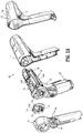
- a surgical device 10 in accordance with an embodiment of the present disclosure, is in the form of a powered handheld electromechanical instrument.
- the surgical device 10 includes a handle assembly 100, an adapter assembly 200, and a tool assembly or end effector 300.
- the handle assembly 100 is configured for selective connection with the adapter assembly 200 and, in turn, the adapter assembly 200 is configured for selective connection with the end effector 300.
- the handle assembly 100 includes an outer housing shell 112, including a proximal half-section 112a and a distal half-section 112b, and an inner handle housing 114 disposed within the outer housing shell 112.
- the outer housing shell 112 includes a plurality of actuators 116 (e.g., finger-actuated control buttons, knobs, toggles, slides, interfaces, and the like) for activating various functions of the surgical device 10 ( FIG. 1 ), and the inner handle housing 114 houses a power-pack 120 configured to power and control various operations of the surgical device 10.
- the power-pack 120 includes a rechargeable battery 122 configured to supply power to any of the electrical components of the surgical device 10, a battery circuit board 124, and a controller circuit board 126.
- the controller circuit board 126 includes a motor controller circuit board 126a, a main controller circuit board 126b, and a first ribbon cable 126c interconnecting the motor controller circuit board 126a and the main controller circuit board 126b.
- the motor controller circuit board 126a is communicatively coupled with the battery circuit board 124 enabling communication therebetween and between the battery circuit board 124 and the main controller circuit board 126b.
- the main controller circuit board 126a includes a 1-wire communication system including three 1-wire buses which enables communication between the power-pack 120 and the battery 122, the power-pack 120 and the adapter assembly 200 ( FIG. 1 ), and the power-pack 120 and the outer shell housing 112.
- the 1-wire bus establishes a communication line between a 1-wire master chip of the main controller circuit board 126b and a 1-wire memory chip of a circuit board 224 ( FIG. 3B ) of the adapter assembly 200.
- This communication line allows for calibration and communication of data and control signals between the handle assembly 100 and the adapter assembly 200, and enables information stored in the 1-wire memory chip of the circuit board 224 of the adapter assembly 200 to be accessed, updated, and/or incremented by the power-pack 120.
- the power-pack 120 further includes motors 128 (e.g., a first motor 128a, a second motor 128b, and a third motor 128c) each electrically connected to the controller circuit board 126 and the battery 122.
- the motors 128a, 128b, 128c are disposed between the motor controller circuit board 126a and the main controller circuit board 126b.
- Each of the motors 128a, 128b, 128c includes a respective motor shaft 129a, 129b, 129c extending therefrom for transmitting rotative forces or torque.
- Each of the motors 128a, 128b, 128c is controlled by a respective motor controller (not shown) disposed on the motor controller circuit board 126a, and each motor controller is electrically coupled to a main controller or master chip disposed on the main controller circuit board 126b via the first ribbon cable 126c which connects the motor controller circuit board 126a with the main controller circuit board 126b.
- the master chip is also coupled to memory, which is also disposed on the main controller circuit board 126b.
- Each of the motor 128a, 128b, 128c is supported on a motor bracket 130 such that the motor shafts 129a, 129b, 129c are rotatably disposed within respective apertures of the motor bracket 130.
- the motor bracket 130 rotatably supports three rotatable drive connector sleeves 132a, 132b, 132c that are keyed to respective motor shafts 129a, 129b, 129c of the motors 128a, 128b, 128c.
- the drive connector sleeves 132a, 132b, 132c non-rotatably receive proximal ends of respective coupling shafts 142a, 142b, 142c of a plate assembly 140 of the handle assembly 100, when the power-pack 120 is disposed within the outer shell housing 112.
- the motor bracket 130 also supports an electrical adapter interface receptacle 134.
- the electrical adapter interface receptacle 134 is in electrical connection with the main controller circuit board 126b by a second ribbon cable 126d.
- the electrical adapter interface receptacle 134 defines a plurality of electrical slots for receiving respective electrical contacts or blades extending from a pass-through connector 144 of the plate assembly 140 of the handle assembly 100.
- Rotation of the motor shafts 129a, 129b, 129c by respective motors 128a, 128b, 128c function to drive shafts and/or gear components of the adapter assembly 200 in order to perform the various operations of the surgical device 10.
- the motors 128a, 128b, 128c of the power-pack 120 are configured to drive shafts and/or gear components of the adapter assembly 200 in order to selectively move a tool assembly 320 ( FIG. 4A ) of the end effector 300 relative to a proximal body portion 310 ( FIG. 4A ) of the end effector 300, to rotate the end effector 300 about a longitudinal axis "X" ( FIG. 4A ), to move a cartridge assembly 340 ( FIG. 4A ) relative to an anvil assembly 330 ( FIG. 4A ) of the end effector 300, and/or to fire staples from within the cartridge assembly 340 of the end effector 300.
- the adapter assembly 200 includes an outer knob housing or connector housing 202 and an outer tube or sleeve 204 extending distally from the outer knob housing 202 and terminating at a distal cap 206.
- the outer knob housing 202 is configured for operable connection to the handle assembly 100 ( FIG. 1 ) and the outer tube 204 is configured for operable connection to the end effector 300 ( FIG. 1 ).
- Rotatable connector sleeves 210a, 210b, 210c are disposed within the outer knob housing 202 and are configured and adapted to mate, through a keyed and/or substantially non-rotatable interface, with respective coupling shafts 142a, 142b, 142c ( FIG. 2A ) of the plate assembly 140 of the handle housing 100 such that rotation of each of the coupling shafts 142a, 142b, 142c causes a corresponding rotation of the corresponding connector sleeve 210a, 210b, 210c of the adapter assembly 200.
- the mating of the coupling shafts 142a, 142b, 142c of the handle assembly 100 with the connector sleeves 210a, 210b, 210c of the adapter assembly 200 allows rotational forces to be independently transmitted via each of the three respective connector interfaces.
- the coupling shafts 142a, 142b, 142c of the handle assembly 100 are configured to be independently rotated by respective motors 128a, 128b, 128c such that rotational force(s) are selectively transferred from the motor(s) 128a, 128b, 128c of the handle assembly 100 to the adapter assembly 200.
- Adapter assembly 200 includes a plurality of force/rotation transmitting/converting assemblies (not shown), each disposed within an inner housing assembly (not shown) of the outer knob housing 202 and the outer tube 204.
- Each force/rotation transmitting/converting assembly is configured and adapted to transmit/convert a speed/force of rotation (e.g., increase or decrease) of the coupling shafts 142a, 142b, 142c ( FIG. 2A ) of the handle assembly 100 before transmission of such rotational speed/force to the end effector 300.
- each force/rotation transmitting/converting assembly is configured and adapted to transmit or convert a rotation of the first, second and third coupling shafts 142a, 142b, 142c of the handle assembly 100 into: axial translation of an articulation bar (not shown) of the adapter assembly 200 to effectuate articulation of the end effector 300 ( FIG. 1 ); a rotation of a ring gear (not shown) of the adapter assembly 200 to effectuate rotation of the adapter assembly 200, and thus, the end effector 300; or axial translation of a distal drive member (not shown) of the adapter assembly 200 to effectuate closing, opening, and firing of the end effector 300.
- an electrical assembly 220 is supported on and in outer knob housing 202.
- the electrical assembly 220 includes a plurality of electrical contact blades 222 supported on a circuit board 224 for electrical connection to pass-through connector 144 ( FIG. 2A ) of the plate assembly 140 of the handle assembly 100.
- the electrical assembly 220 also includes a strain gauge 226 electrically connected to the circuit board 224 for closed-loop feedback of firing/clamping loads exhibited by the adapter assembly 200 and regulated by the power-pack 120 ( FIG. 2A ), which sets the speed current limit on the appropriate motor 128a, 128b, 128c ( FIG. 2B ).
- the circuit board 224 includes a memory configured to store data relating to the adapter assembly 200 such as unique ID information (electronic serial number); type information; status information; whether an end effector has been detected, identified, and verified; usage count data; and assumed autoclave count data.
- the electrical assembly 220 serves to allow for calibration and communication of information (e.g., identifying information, life-cycle information, system information, force information) to the main controller circuit board 126b ( FIG. 2A ) of the power-pack 120 via the electrical adapter interface receptacle 134 ( FIG. 2B ) of the power-pack 120 of the handle assembly 100.
- the adapter assembly 200 further includes a switch 230, a sensor link or switch actuator 240, and an annular member 250, each of which is disposed within a distal portion 204a of the outer tube 204.
- the switch 230 is configured to toggle in response to a coupling of the end effector 300 ( FIG. 1 ) to the outer tube 204.
- the switch 230 is mounted on a printed circuit board 232 that is electrically connected with the controller circuit board 126 ( FIG. 2A ) of the power-pack 120 of the handle housing 100.
- the switch 230 is configured to couple to a memory 352 ( FIG. 4C ) of the end effector 300.
- the memory 352 of the end effector 300 is configured to store data pertaining to the end effector 300 and is configured to provide the data to the controller circuit board 126 of the handle assembly 100 in response to coupling of the end effector 300 to the outer tube 204.
- the power-pack 120 monitors communication between the power-pack 120 and the adapter assembly 200 and is able to detect that the end effector 300 is engaged to or disengaged from the distal portion 204a of the outer tube 204 by recognizing that the switch 230 has been toggled.
- the switch actuator 240 is slidingly disposed within the distal portion 204a of the outer tube 204.
- the switch actuator 240 is longitudinally movable between proximal and distal portions, and toggles the switch 230 during movement between the proximal and distal positions.
- the annular member 250 is rotatably disposed within an inner housing 208 which, in turn, is disposed within the outer tube 204 ( FIG. 3A ).
- the annular member 250 extends from a proximal end 250a to a distal end 250b, and defines a cylindrical passageway 251 therethrough configured for disposal of an outer housing 312 ( FIG. 4A ) of the end effector 300.
- the annular member 250 includes a longitudinal bar 252 interconnecting a first ring 254 at the proximal end 250a of the annular member 250 and a second ring 256 at the distal end 250b of the annular member 250.
- the first ring 254 includes a pair of electrical contacts 258 electrically coupled to the switch 230 via wires 234, the wires 234 extending to the electrical assembly 220 ( FIG. 3B ) to electrically couple the switch 230 with the circuit board 224 of the adapter assembly 200.
- the electrical contacts 258 are configured to engage corresponding electrical contacts 356 ( FIG. 4C ) of the end effector 300, such that the switch 240 and the annular member 250 are capable of transferring data pertaining to the end effector 300 therebetween, ultimately for communication with the power-pack 120, as described in greater detail below.
- the end effector 300 is in the form of a single use loading unit. It should be understood, however, that other types of end effectors may also be used with the surgical device 10 of the present disclosure including, for example, end-to-end anastomosis loading units, multi-use loading units, transverse loading units, and curved loading units. As discussed below, the particular end effector 300 utilized with the surgical device 10 is recognized by the power-pack 120 ( FIG. 2A ) of the handle assembly 100 to enable appropriate operation thereof.
- the end effector 300 includes a proximal body portion 310 and a tool assembly 320.
- the proximal body portion 310 is releasably attachable to the distal cap 206 ( FIG. 3A ) of the adapter assembly 200 and the tool assembly 320 is pivotally attached to the proximal body portion 310.
- the tool assembly 320 includes an anvil assembly 330 and a cartridge assembly 340.
- the cartridge assembly 340 is pivotal in relation to the anvil assembly 300, and is movable between an open or unclamped position and a closed or clamped position for insertion through a cannula of a trocar.
- the anvil assembly 330 includes an anvil plate 331a having a longitudinal slot 332a formed therein, and a cover plate 331b having an inner surface 331c secured over the anvil plate 331a such that the cover plate 331b defines an outer surface 334 of the anvil assembly 330.
- the anvil plate 331a includes a plurality of staple forming pockets 332b defined in a tissue contacting surface 332 thereof.
- the cartridge assembly 340 includes a staple cartridge 341a and a cartridge carrier 341b.
- the cartridge carrier 341b has an inner surface 341c defining an elongated support channel 343 configured and dimensioned to selectively receive the staple cartridge 341a therein such that the cartridge carrier 341b defines an outer surface 344 of the cartridge assembly 340.
- the staple cartridge 341a includes a tissue contacting surface 342 defining staple pockets or retention slots 345 formed therein for receiving a plurality of fasteners or staples (not shown) and a longitudinal slot 342a formed in and extending along a substantial length of the staple cartridge 341a.
- the proximal body portion 310 of the end effector 300 includes a drive assembly 315 operably associated with and slidably disposable between the anvil and cartridge assemblies 330, 340 for driving the ejection of staples (not shown) from the cartridge assembly 340 of the tool assembly 320, and an articulation link (not shown) for effectuating an articulation of the tool assembly 320.
- the drive assembly 315 includes an elongated drive beam 316 and an I-beam 317 having a central wall portion 318 including a knife 319.
- the knife 319 can travel through the longitudinal slots 332a, 342a defined in the tissue contacting surfaces 332, 342 of the anvil and cartridge assemblies 330, 340, between the staple forming pockets 332b and the retention slots 345 also defined in the respective tissue contacting surfaces 332, 342, to longitudinally cut stapled tissue.
- the anvil assembly 330 and the cartridge assembly 340 include respective tissue contacting surfaces 332, 342 between which tissue is grasped, and respective outer surfaces 334, 344.
- the anvil assembly 330 includes one or more sensors 336 disposed on the outer surface 334 thereof.
- the sensors 336 may be any sensor configured to detect a mechanical property of anvil assembly 330 such that a behavior of the tissue (e.g., target tissue) may be monitored while under a loading condition (e.g., during clamping and/or firing of the end effector 300).
- the sensors 336 may be, for example, strain gauges, piezoelectric sensors (e.g., films, cables crystals, etc.), accelerometers, pressure sensors, lasers (e.g., for displacement measurements), and combinations thereof that detect stress, relaxation, strain, creep, mechanical energy, and/or mechanical power, etc., input into the tool assembly 320, and in turn, into the tissue clamped therein.
- one or more of the sensors 336 may be configured to measure a physiological parameter of tissue adjacent to the tool assembly 320.
- sensors include, for example, a conductivity/resistivity sensor; an optical sensor such as a CCD or CMOS image sensor; an electrical, electrochemical, or chemical sensor for measuring characteristics such as impedance, temperature, or pH; a biochemical sensor; an acoustic sensor such as an ultrasound; a light sensor such as a photodiode; and other sensors within the purview of those skilled in the art for measuring and/or identifying a physiological condition or state of the target tissue and/or the adjacent tissue.
- the sensors 336 are shown disposed in spaced relation relative to each other linearly along the outer surface 334 of the anvil assembly 330. It should be understood that the number of sensors 336 and the configuration of the sensors 336 on the outer surface 334 of the anvil assembly 300 may be modified. For example, the sensors 336 may measure the same mechanical property in replicates (e.g., duplicate or triplicate) to improve and/or verify the accuracy of measurement. As another example, the sensors 336 may detect multiple mechanical properties to provide more information about the behavior of the tissue.
- the sensors 336 may be spaced along the entire length of the outer surface 334 of the anvil assembly 330 to monitor characteristics and mechanical properties of the tool assembly 320, for different tissue clamped in tool assembly 320, and in turn, corresponding behavior of the target tissue along the length of the target tissue.
- Sensors 336 may additionally or alternatively be disposed on the inner surface 331c of the anvil assembly 330 in a similar manner as the sensors 336 disposed on the outer surface 334 of the anvil assembly 330, as discussed above. Positioning the sensors 336 on the inner and/or outer surfaces 331c, 334 of the anvil assembly 330 allows for measurements of the desired metric(s) of the tissue disposed within the tool assembly 320 of the end effector 300 indirectly, without having to touch the tissue directly with the sensors 336.
- the sensors 336 may be strain gauges configured to measure deformation of the anvil assembly 330 due to the force exerted on the anvil assembly 330 by the tissue compressed within the tool assembly 320. Accordingly, varying the position of the sensors 336 about the tool assembly 320 and/or increasing the number of sensors 336 disposed thereon may improve resolution of the tissue measurements (e.g., tissue compression forces).
- sensor(s) 336 on the inner and/or outer surfaces 341c, 344 of the cartridge assembly 340 (not explicitly shown), and/or on the knife 319 ( FIG. 4B ) of the drive assembly 315.
- sensor(s) 336 may also be disposed on the tissue contacting surface 332, 342 of the anvil and/or cartridge assemblies 330, 340.
- the sensors 336 may be positioned on the tissue contacting surface 332, 342 such that they do not interfere with deployment of the knife and/or staples (e.g., without covering the longitudinal slot 332a and the staple forming pockets 332b of the anvil assembly 330).
- the sensors 336 may be positioned at proximal and distal end portions of the tissue contacting surface 332 of the anvil assembly 330, outside the area of the tissue contacting surface 332 including the staple forming pockets 332b.
- Other configurations are envisioned for the positioning or placement of sensor(s) 336, such as adjacent the longitudinal slot 332a and/or between the staple forming pockets 332b in a linear or staggered spaced arrangement along the length of the tissue contacting surface 332.
- Sensors 336 disposed on the tissue contacting surface 332, 342 of the anvil and/or cartridge assemblies 330, 340, as well as on the outer surface 334, 344 of the anvil and/or cartridge assemblies 330, 340 may cooperate together (e.g., direct and indirect tissue contact measurements) to aid in detecting properties, conditions, and/or behaviors of the end effector 300, the tissue, and/or the tissue environment.
- sensors (not explicitly shown) disposed on the tissue contacting surface 332, 342 of the anvil and/or cartridge assemblies 330, 340 may be configured to measure properties of the tissue clamped between the anvil and/or cartridge assemblies 330, 340 (e.g., tissue thickness or clamping force), and the sensors 336 disposed on the outer surface 334, 344 of the anvil and/or cartridge assembly 330, 340 may be configured to measure properties of the surrounding tissue (e.g., mechanical response to clamping) to determine deployment timing and completion of staple formation.
- the end effector 300 further includes an outer housing 312 and an inner housing 314 (shown in phantom) disposed within the outer housing 312.
- a proximal end of the outer housing 312 is sized and dimensioned to be inserted through the distal cap 206 ( FIG. 3A ) of the adapter assembly 200 to engage the adapter assembly 200.
- the end effector 300 includes a microcontroller 350 and a memory 352, each of which is disposed within or on the inner housing 314.
- the microcontroller 350 is electrically coupled to the sensors 336 and the memory 352 of the anvil assembly 330.
- the microcontroller 350 is configured to receive and/or measure electrical signals from the sensors 336 and record them in the memory 352.
- the memory 352 includes a memory chip 354 and a pair of electrical contacts 356 electrically connected to the memory chip 354.
- the memory 352 is configured to store the sensor data received from the microcontroller 250.
- the sensor data may include, for example, stress measurements along anvil assembly 330 among other desired monitored properties, and, in turn converted, via an algorithm, into corresponding tissue stress measurements, among other desired monitored tissue properties and/or behaviors associated with the type of sensor 336 utilized in the end effector 300, as described above.
- the memory chip 354 is also configured to store one or more parameters related to the end effector 300.
- the parameters include, for example, a serial number of a loading unit, a type of loading unit, a size of loading unit, a staple size, information identifying whether the loading unit has been fired, a length of a loading unit, maximum number of uses of a loading unit, and combinations thereof.
- the memory chip 354 is configured to communicate to the handle assembly 100 the sensor data and/or parameters of the end effector 300, as described above, via the electrical contacts 356, upon engagement of the end effector 300 with the adapter assembly 200, as described below.
- the sensors 336 may send analog signals (e.g., along a wire), or use wireless communication, to send the sensor data to the microcontroller 350.
- the sensor data and/or parameters may be processed in the controller circuit board 126 of the handle assembly 100, or in some other remote processor or the like.
- the electrical contacts 356 are disposed on an outer surface of the inner housing 314 and are configured to engage the electrical contacts 258 ( FIG. 3D ) of the annular member 250 of the adapter assembly 200 upon insertion of the end effector 300 into the adapter assembly 200. This connection between the electrical contacts 356 of the end effector 300 and the electrical contacts 258 of the adapter assembly 200 allows for communication between the memory chip 354 of the end effector 300 and the controller circuit board 126 ( FIG. 2A ) of the power-pack 120 of the handle assembly 100.
- the switch actuator 240 In operation, upon initial insertion of the end effector 300 into the adapter assembly 200, the switch actuator 240 remains disengaged from the switch 230. With the switch 230 in the unactuated state, there is no electrical connection established between the memory 352 of the end effector 300 and the controller circuit board 126 of the handle assembly 100. Upon a rotation of the end effector 300, the end effector 300 engages the adapter assembly 200 and moves the switch actuator 240 distally, which toggles the switch 230 to actuate the switch 230.
- the switch 230 With the switch 230 in the actuated state, an electrical connection is established between the memory chip 354 of the end effector 300 and the controller circuit board 126 of the handle assembly 100, through which information about the end effector 300 is communicated to the controller circuit board 126 of the handle assembly 100.
- the handle assembly 100 Upon both the actuation of the switch 230 and the establishment of a wiping contact between the electrical contacts 356 of the inner housing 314 of the end effector 300 and the electrical contacts 258 of the annular member 250 of the adapter assembly 200, the handle assembly 100 is able to detect that the end effector 300 is engaged with the adapter assembly 200 and to identify one or more parameters of the end effector 300 and/or to process the sensor data from the sensors 336 of the end effector 300. Accordingly, the power-pack 120 is capable of reading the information stored in the memory 352 of the end effector 300 via the adapter assembly 200.
- the sensors 336 of the end effector 300 detect and/or measure mechanical behaviors and/or properties of the tool assembly 320 (specifically anvil assembly 330) in real time during a surgical procedure.
- the sensor data is transmitted to the microcontroller 350 for processing, stored in the memory 352, and ultimately transferred to the power-pack 120 of the handle assembly 100 via the adapter assembly 200 along the 1-wire bus, or other communication protocol.
- the power-pack 120 collects and processes the sensor data in real time, and transmits electrical control signals to the motors 128a, 128b, 128c of the handle assembly 100 to control a function of the surgical device 10 (e.g., to change an operating parameter, such as pre-compression time, speed of firing, etc.).
- the mechanical behaviors and/or properties of the tool assembly 320 detected/measured by sensors 336 are then converted and/or correlated to real time, or near real time, behaviors and/or properties of the target tissue (clamped in the tool assembly 320).
- the end effector 300 is placed at a desired surgical site and the anvil assembly 330 and the cartridge assembly 340 are approximated and clamped to grasp target tissue between the respective tissue contacting surfaces 332, 342 of the anvil and cartridge assemblies 330, 340.
- One or more of the sensors 336 are strain gauges for measuring stress in the anvil and cartridge assemblies 330, 340, and in turn, for measuring stress in the target tissue, by monitoring a change in resistance through the strain gauges.
- the sensor 336 measure a deformation of the anvil assembly 330 and/or the cartridge assembly 340, or any portion(s) thereof, due to forces exerted thereon by compressed tissue in the end effector 300.
- the resistance of the sensors 336 (e.g., strain gauges) is sent to the microcontroller 350 of the end effector 300 which, in turn, processes the resistance to calculate a force or pressure on the strain gauges which, ultimately, is transmitted to the power-pack 120 of the handle assembly 100 via the adapter assembly 200.
- the power-pack 120 processes the sensor data and controls the wait time between clamping of the target tissue and firing of staples from the cartridge assembly 340 until a stress on the target tissue is at a value within an acceptable range of values.
- the microcontroller 350 may continuously or intermittently monitor the sensors 336 for collection of the sensor data.
- the handle assembly 100 may provide a visual or audible indication to a user that the surgical device 10 is ready for firing.
- the wait time is beneficial to minimize or avoid negative acute events related to excess stress in the target tissue, such as bruising, tearing, and bleeding.
- the sensors 336 control the firing of the surgical device 10 to keep the target tissue stress within an ideal stress region which is beneficial for sealing the target tissue, allowing perfusion for healing, providing hemostasis and pneumostasis, and/or preventing leakage.
- the use of sensors 336 enables the compression on the tissue, by the anvil assembly 330 and the cartridge assembly 340, to be measured indirectly (e.g., without the sensor(s) 336 touching the tissue).
- the compression on the tissue is calculated by the microcontroller 350, or the like, from variables including, but not limited to, the type of tissue being clamped, the dimensions and material properties of the anvil assembly 330 and the cartridge assembly 340, the amount of time for the clamping, a change in resistance through sensor(s) 336, etc.
- the sensors 336 of the end effector 300 of the present disclosure provides a method of monitoring the target tissue stress and delaying and/or slowing the speed of firing until the target tissue stress is below a value that negatively affects staple formation.
- handle assemblies 100, the adapter assembly 200, and the end effector 300 may be modified depending on the desired use of the surgical device 10 of the present disclosure.
- handle assemblies, end effectors and/or adapter assemblies of the present disclosure may be configured to perform, for example, endoscopic gastro-intestinal anastomosis (EGIA) procedures or end-to-end anastomosis (EEA) procedures.
- ESA endoscopic gastro-intestinal anastomosis
- EOA end-to-end anastomosis
Landscapes
- Health & Medical Sciences (AREA)
- Life Sciences & Earth Sciences (AREA)
- Surgery (AREA)
- Heart & Thoracic Surgery (AREA)
- Engineering & Computer Science (AREA)
- Biomedical Technology (AREA)
- Nuclear Medicine, Radiotherapy & Molecular Imaging (AREA)
- Medical Informatics (AREA)
- Molecular Biology (AREA)
- Animal Behavior & Ethology (AREA)
- General Health & Medical Sciences (AREA)
- Public Health (AREA)
- Veterinary Medicine (AREA)
- Surgical Instruments (AREA)
Applications Claiming Priority (2)
| Application Number | Priority Date | Filing Date | Title |
|---|---|---|---|
| US201762466481P | 2017-03-03 | 2017-03-03 | |
| US15/887,024 US20180250002A1 (en) | 2017-03-03 | 2018-02-02 | Powered surgical devices having tissue sensing function |
Publications (3)
| Publication Number | Publication Date |
|---|---|
| EP3369385A2 true EP3369385A2 (de) | 2018-09-05 |
| EP3369385A3 EP3369385A3 (de) | 2019-02-27 |
| EP3369385B1 EP3369385B1 (de) | 2021-01-20 |
Family
ID=61526672
Family Applications (1)
| Application Number | Title | Priority Date | Filing Date |
|---|---|---|---|
| EP18159314.6A Not-in-force EP3369385B1 (de) | 2017-03-03 | 2018-02-28 | Angetriebene chirurgische vorrichtungen mit gewebeerfassungsfunktion |
Country Status (3)
| Country | Link |
|---|---|
| US (2) | US20180250002A1 (de) |
| EP (1) | EP3369385B1 (de) |
| CN (1) | CN108542453A (de) |
Cited By (2)
| Publication number | Priority date | Publication date | Assignee | Title |
|---|---|---|---|---|
| EP3646800A1 (de) * | 2018-10-30 | 2020-05-06 | Covidien LP | Lasterfassende vorrichtungen zur verwendung in chirurgischen instrumenten |
| US20250160993A1 (en) * | 2023-11-22 | 2025-05-22 | Cilag Gmbh International | Processing and display of tissue tension |
Families Citing this family (204)
| Publication number | Priority date | Publication date | Assignee | Title |
|---|---|---|---|---|
| US9060770B2 (en) | 2003-05-20 | 2015-06-23 | Ethicon Endo-Surgery, Inc. | Robotically-driven surgical instrument with E-beam driver |
| US20070084897A1 (en) | 2003-05-20 | 2007-04-19 | Shelton Frederick E Iv | Articulating surgical stapling instrument incorporating a two-piece e-beam firing mechanism |
| US11890012B2 (en) | 2004-07-28 | 2024-02-06 | Cilag Gmbh International | Staple cartridge comprising cartridge body and attached support |
| US11998198B2 (en) | 2004-07-28 | 2024-06-04 | Cilag Gmbh International | Surgical stapling instrument incorporating a two-piece E-beam firing mechanism |
| US9072535B2 (en) | 2011-05-27 | 2015-07-07 | Ethicon Endo-Surgery, Inc. | Surgical stapling instruments with rotatable staple deployment arrangements |
| US10159482B2 (en) | 2005-08-31 | 2018-12-25 | Ethicon Llc | Fastener cartridge assembly comprising a fixed anvil and different staple heights |
| US7669746B2 (en) | 2005-08-31 | 2010-03-02 | Ethicon Endo-Surgery, Inc. | Staple cartridges for forming staples having differing formed staple heights |
| US11246590B2 (en) | 2005-08-31 | 2022-02-15 | Cilag Gmbh International | Staple cartridge including staple drivers having different unfired heights |
| US20120292367A1 (en) | 2006-01-31 | 2012-11-22 | Ethicon Endo-Surgery, Inc. | Robotically-controlled end effector |
| US8708213B2 (en) | 2006-01-31 | 2014-04-29 | Ethicon Endo-Surgery, Inc. | Surgical instrument having a feedback system |
| US7845537B2 (en) | 2006-01-31 | 2010-12-07 | Ethicon Endo-Surgery, Inc. | Surgical instrument having recording capabilities |
| US11793518B2 (en) | 2006-01-31 | 2023-10-24 | Cilag Gmbh International | Powered surgical instruments with firing system lockout arrangements |
| US8186555B2 (en) | 2006-01-31 | 2012-05-29 | Ethicon Endo-Surgery, Inc. | Motor-driven surgical cutting and fastening instrument with mechanical closure system |
| US8992422B2 (en) | 2006-03-23 | 2015-03-31 | Ethicon Endo-Surgery, Inc. | Robotically-controlled endoscopic accessory channel |
| US10568652B2 (en) | 2006-09-29 | 2020-02-25 | Ethicon Llc | Surgical staples having attached drivers of different heights and stapling instruments for deploying the same |
| US11980366B2 (en) | 2006-10-03 | 2024-05-14 | Cilag Gmbh International | Surgical instrument |
| US8684253B2 (en) | 2007-01-10 | 2014-04-01 | Ethicon Endo-Surgery, Inc. | Surgical instrument with wireless communication between a control unit of a robotic system and remote sensor |
| US8632535B2 (en) | 2007-01-10 | 2014-01-21 | Ethicon Endo-Surgery, Inc. | Interlock and surgical instrument including same |
| US20080169332A1 (en) | 2007-01-11 | 2008-07-17 | Shelton Frederick E | Surgical stapling device with a curved cutting member |
| US8931682B2 (en) | 2007-06-04 | 2015-01-13 | Ethicon Endo-Surgery, Inc. | Robotically-controlled shaft based rotary drive systems for surgical instruments |
| US11857181B2 (en) | 2007-06-04 | 2024-01-02 | Cilag Gmbh International | Robotically-controlled shaft based rotary drive systems for surgical instruments |
| US11849941B2 (en) | 2007-06-29 | 2023-12-26 | Cilag Gmbh International | Staple cartridge having staple cavities extending at a transverse angle relative to a longitudinal cartridge axis |
| US8573465B2 (en) | 2008-02-14 | 2013-11-05 | Ethicon Endo-Surgery, Inc. | Robotically-controlled surgical end effector system with rotary actuated closure systems |
| RU2493788C2 (ru) | 2008-02-14 | 2013-09-27 | Этикон Эндо-Серджери, Инк. | Хирургический режущий и крепежный инструмент, имеющий радиочастотные электроды |
| US8636736B2 (en) | 2008-02-14 | 2014-01-28 | Ethicon Endo-Surgery, Inc. | Motorized surgical cutting and fastening instrument |
| US11986183B2 (en) | 2008-02-14 | 2024-05-21 | Cilag Gmbh International | Surgical cutting and fastening instrument comprising a plurality of sensors to measure an electrical parameter |
| US20130153641A1 (en) | 2008-02-15 | 2013-06-20 | Ethicon Endo-Surgery, Inc. | Releasable layer of material and surgical end effector having the same |
| US9005230B2 (en) | 2008-09-23 | 2015-04-14 | Ethicon Endo-Surgery, Inc. | Motorized surgical instrument |
| US9386983B2 (en) | 2008-09-23 | 2016-07-12 | Ethicon Endo-Surgery, Llc | Robotically-controlled motorized surgical instrument |
| US8210411B2 (en) | 2008-09-23 | 2012-07-03 | Ethicon Endo-Surgery, Inc. | Motor-driven surgical cutting instrument |
| US11648005B2 (en) | 2008-09-23 | 2023-05-16 | Cilag Gmbh International | Robotically-controlled motorized surgical instrument with an end effector |
| US8608045B2 (en) | 2008-10-10 | 2013-12-17 | Ethicon Endo-Sugery, Inc. | Powered surgical cutting and stapling apparatus with manually retractable firing system |
| US8220688B2 (en) | 2009-12-24 | 2012-07-17 | Ethicon Endo-Surgery, Inc. | Motor-driven surgical cutting instrument with electric actuator directional control assembly |
| US10405854B2 (en) | 2010-09-30 | 2019-09-10 | Ethicon Llc | Surgical stapling cartridge with layer retention features |
| US11925354B2 (en) | 2010-09-30 | 2024-03-12 | Cilag Gmbh International | Staple cartridge comprising staples positioned within a compressible portion thereof |
| US9320523B2 (en) | 2012-03-28 | 2016-04-26 | Ethicon Endo-Surgery, Llc | Tissue thickness compensator comprising tissue ingrowth features |
| US12213666B2 (en) | 2010-09-30 | 2025-02-04 | Cilag Gmbh International | Tissue thickness compensator comprising layers |
| US9629814B2 (en) | 2010-09-30 | 2017-04-25 | Ethicon Endo-Surgery, Llc | Tissue thickness compensator configured to redistribute compressive forces |
| US11812965B2 (en) | 2010-09-30 | 2023-11-14 | Cilag Gmbh International | Layer of material for a surgical end effector |
| US10945731B2 (en) | 2010-09-30 | 2021-03-16 | Ethicon Llc | Tissue thickness compensator comprising controlled release and expansion |
| US8695866B2 (en) | 2010-10-01 | 2014-04-15 | Ethicon Endo-Surgery, Inc. | Surgical instrument having a power control circuit |
| BR112013027794B1 (pt) | 2011-04-29 | 2020-12-15 | Ethicon Endo-Surgery, Inc | Conjunto de cartucho de grampos |
| US11207064B2 (en) | 2011-05-27 | 2021-12-28 | Cilag Gmbh International | Automated end effector component reloading system for use with a robotic system |
| MX358135B (es) | 2012-03-28 | 2018-08-06 | Ethicon Endo Surgery Inc | Compensador de grosor de tejido que comprende una pluralidad de capas. |
| MX350846B (es) | 2012-03-28 | 2017-09-22 | Ethicon Endo Surgery Inc | Compensador de grosor de tejido que comprende cápsulas que definen un ambiente de baja presión. |
| US9101358B2 (en) | 2012-06-15 | 2015-08-11 | Ethicon Endo-Surgery, Inc. | Articulatable surgical instrument comprising a firing drive |
| US12383267B2 (en) | 2012-06-28 | 2025-08-12 | Cilag Gmbh International | Robotically powered surgical device with manually-actuatable reversing system |
| US9289256B2 (en) | 2012-06-28 | 2016-03-22 | Ethicon Endo-Surgery, Llc | Surgical end effectors having angled tissue-contacting surfaces |
| US20140001231A1 (en) | 2012-06-28 | 2014-01-02 | Ethicon Endo-Surgery, Inc. | Firing system lockout arrangements for surgical instruments |
| RU2669463C2 (ru) | 2013-03-01 | 2018-10-11 | Этикон Эндо-Серджери, Инк. | Хирургический инструмент с мягким упором |
| MX368026B (es) | 2013-03-01 | 2019-09-12 | Ethicon Endo Surgery Inc | Instrumento quirúrgico articulable con vías conductoras para la comunicación de la señal. |
| US9629629B2 (en) | 2013-03-14 | 2017-04-25 | Ethicon Endo-Surgey, LLC | Control systems for surgical instruments |
| BR112015026109B1 (pt) | 2013-04-16 | 2022-02-22 | Ethicon Endo-Surgery, Inc | Instrumento cirúrgico |
| US20150053737A1 (en) | 2013-08-23 | 2015-02-26 | Ethicon Endo-Surgery, Inc. | End effector detection systems for surgical instruments |
| US10013049B2 (en) | 2014-03-26 | 2018-07-03 | Ethicon Llc | Power management through sleep options of segmented circuit and wake up control |
| US12232723B2 (en) | 2014-03-26 | 2025-02-25 | Cilag Gmbh International | Systems and methods for controlling a segmented circuit |
| US9750499B2 (en) | 2014-03-26 | 2017-09-05 | Ethicon Llc | Surgical stapling instrument system |
| CN106456158B (zh) | 2014-04-16 | 2019-02-05 | 伊西康内外科有限责任公司 | 包括非一致紧固件的紧固件仓 |
| CN106456176B (zh) | 2014-04-16 | 2019-06-28 | 伊西康内外科有限责任公司 | 包括具有不同构型的延伸部的紧固件仓 |
| US20150297223A1 (en) | 2014-04-16 | 2015-10-22 | Ethicon Endo-Surgery, Inc. | Fastener cartridges including extensions having different configurations |
| JP6532889B2 (ja) | 2014-04-16 | 2019-06-19 | エシコン エルエルシーEthicon LLC | 締結具カートリッジ組立体及びステープル保持具カバー配置構成 |
| US10327764B2 (en) | 2014-09-26 | 2019-06-25 | Ethicon Llc | Method for creating a flexible staple line |
| US11311294B2 (en) | 2014-09-05 | 2022-04-26 | Cilag Gmbh International | Powered medical device including measurement of closure state of jaws |
| BR112017004361B1 (pt) | 2014-09-05 | 2023-04-11 | Ethicon Llc | Sistema eletrônico para um instrumento cirúrgico |
| US9724094B2 (en) | 2014-09-05 | 2017-08-08 | Ethicon Llc | Adjunct with integrated sensors to quantify tissue compression |
| US10105142B2 (en) | 2014-09-18 | 2018-10-23 | Ethicon Llc | Surgical stapler with plurality of cutting elements |
| US11523821B2 (en) | 2014-09-26 | 2022-12-13 | Cilag Gmbh International | Method for creating a flexible staple line |
| US9924944B2 (en) | 2014-10-16 | 2018-03-27 | Ethicon Llc | Staple cartridge comprising an adjunct material |
| US10517594B2 (en) | 2014-10-29 | 2019-12-31 | Ethicon Llc | Cartridge assemblies for surgical staplers |
| US10736636B2 (en) | 2014-12-10 | 2020-08-11 | Ethicon Llc | Articulatable surgical instrument system |
| US9987000B2 (en) | 2014-12-18 | 2018-06-05 | Ethicon Llc | Surgical instrument assembly comprising a flexible articulation system |
| US10085748B2 (en) | 2014-12-18 | 2018-10-02 | Ethicon Llc | Locking arrangements for detachable shaft assemblies with articulatable surgical end effectors |
| RU2703684C2 (ru) | 2014-12-18 | 2019-10-21 | ЭТИКОН ЭНДО-СЕРДЖЕРИ, ЭлЭлСи | Хирургический инструмент с упором, который выполнен с возможностью избирательного перемещения относительно кассеты со скобами вокруг дискретной неподвижной оси |
| US11154301B2 (en) | 2015-02-27 | 2021-10-26 | Cilag Gmbh International | Modular stapling assembly |
| US10441279B2 (en) | 2015-03-06 | 2019-10-15 | Ethicon Llc | Multiple level thresholds to modify operation of powered surgical instruments |
| US9808246B2 (en) | 2015-03-06 | 2017-11-07 | Ethicon Endo-Surgery, Llc | Method of operating a powered surgical instrument |
| US10390825B2 (en) | 2015-03-31 | 2019-08-27 | Ethicon Llc | Surgical instrument with progressive rotary drive systems |
| US10105139B2 (en) | 2015-09-23 | 2018-10-23 | Ethicon Llc | Surgical stapler having downstream current-based motor control |
| US10299878B2 (en) | 2015-09-25 | 2019-05-28 | Ethicon Llc | Implantable adjunct systems for determining adjunct skew |
| US10172620B2 (en) | 2015-09-30 | 2019-01-08 | Ethicon Llc | Compressible adjuncts with bonding nodes |
| US10736633B2 (en) | 2015-09-30 | 2020-08-11 | Ethicon Llc | Compressible adjunct with looping members |
| US11890015B2 (en) | 2015-09-30 | 2024-02-06 | Cilag Gmbh International | Compressible adjunct with crossing spacer fibers |
| US10292704B2 (en) | 2015-12-30 | 2019-05-21 | Ethicon Llc | Mechanisms for compensating for battery pack failure in powered surgical instruments |
| US10265068B2 (en) | 2015-12-30 | 2019-04-23 | Ethicon Llc | Surgical instruments with separable motors and motor control circuits |
| US11213293B2 (en) | 2016-02-09 | 2022-01-04 | Cilag Gmbh International | Articulatable surgical instruments with single articulation link arrangements |
| US10448948B2 (en) | 2016-02-12 | 2019-10-22 | Ethicon Llc | Mechanisms for compensating for drivetrain failure in powered surgical instruments |
| US10357247B2 (en) | 2016-04-15 | 2019-07-23 | Ethicon Llc | Surgical instrument with multiple program responses during a firing motion |
| US10828028B2 (en) | 2016-04-15 | 2020-11-10 | Ethicon Llc | Surgical instrument with multiple program responses during a firing motion |
| US20170296173A1 (en) | 2016-04-18 | 2017-10-19 | Ethicon Endo-Surgery, Llc | Method for operating a surgical instrument |
| US10500000B2 (en) | 2016-08-16 | 2019-12-10 | Ethicon Llc | Surgical tool with manual control of end effector jaws |
| US10568626B2 (en) | 2016-12-21 | 2020-02-25 | Ethicon Llc | Surgical instruments with jaw opening features for increasing a jaw opening distance |
| JP7010956B2 (ja) | 2016-12-21 | 2022-01-26 | エシコン エルエルシー | 組織をステープル留めする方法 |
| US11090048B2 (en) | 2016-12-21 | 2021-08-17 | Cilag Gmbh International | Method for resetting a fuse of a surgical instrument shaft |
| US10758230B2 (en) | 2016-12-21 | 2020-09-01 | Ethicon Llc | Surgical instrument with primary and safety processors |
| US10639035B2 (en) | 2016-12-21 | 2020-05-05 | Ethicon Llc | Surgical stapling instruments and replaceable tool assemblies thereof |
| JP7010957B2 (ja) | 2016-12-21 | 2022-01-26 | エシコン エルエルシー | ロックアウトを備えるシャフトアセンブリ |
| US10779820B2 (en) | 2017-06-20 | 2020-09-22 | Ethicon Llc | Systems and methods for controlling motor speed according to user input for a surgical instrument |
| US10881399B2 (en) | 2017-06-20 | 2021-01-05 | Ethicon Llc | Techniques for adaptive control of motor velocity of a surgical stapling and cutting instrument |
| US10307170B2 (en) | 2017-06-20 | 2019-06-04 | Ethicon Llc | Method for closed loop control of motor velocity of a surgical stapling and cutting instrument |
| US11000279B2 (en) | 2017-06-28 | 2021-05-11 | Ethicon Llc | Surgical instrument comprising an articulation system ratio |
| US10765427B2 (en) | 2017-06-28 | 2020-09-08 | Ethicon Llc | Method for articulating a surgical instrument |
| EP4070740B1 (de) | 2017-06-28 | 2025-03-26 | Cilag GmbH International | Chirurgisches instrument mit selektiv betätigbaren drehbaren kopplern |
| BR112019027065B1 (pt) | 2017-06-28 | 2023-12-26 | Ethicon Llc | Instrumento cirúrgico e sistema cirúrgico |
| USD906355S1 (en) | 2017-06-28 | 2020-12-29 | Ethicon Llc | Display screen or portion thereof with a graphical user interface for a surgical instrument |
| US10932772B2 (en) | 2017-06-29 | 2021-03-02 | Ethicon Llc | Methods for closed loop velocity control for robotic surgical instrument |
| US11944300B2 (en) | 2017-08-03 | 2024-04-02 | Cilag Gmbh International | Method for operating a surgical system bailout |
| US11974742B2 (en) | 2017-08-03 | 2024-05-07 | Cilag Gmbh International | Surgical system comprising an articulation bailout |
| US10695060B2 (en) | 2017-09-01 | 2020-06-30 | RevMedica, Inc. | Loadable power pack for surgical instruments |
| US11331099B2 (en) | 2017-09-01 | 2022-05-17 | Rev Medica, Inc. | Surgical stapler with removable power pack and interchangeable battery pack |
| US10966720B2 (en) | 2017-09-01 | 2021-04-06 | RevMedica, Inc. | Surgical stapler with removable power pack |
| US11134944B2 (en) | 2017-10-30 | 2021-10-05 | Cilag Gmbh International | Surgical stapler knife motion controls |
| US10842490B2 (en) | 2017-10-31 | 2020-11-24 | Ethicon Llc | Cartridge body design with force reduction based on firing completion |
| US10758268B2 (en) | 2017-12-12 | 2020-09-01 | Covidien Lp | Surgical instrument including system for sensing tissue properties and methods thereof |
| US11547439B2 (en) | 2017-12-12 | 2023-01-10 | Covidien Lp | Surgical instruments including devices for sensing tissue properties and methods thereof |
| US10779826B2 (en) | 2017-12-15 | 2020-09-22 | Ethicon Llc | Methods of operating surgical end effectors |
| US10835330B2 (en) | 2017-12-19 | 2020-11-17 | Ethicon Llc | Method for determining the position of a rotatable jaw of a surgical instrument attachment assembly |
| US12336705B2 (en) | 2017-12-21 | 2025-06-24 | Cilag Gmbh International | Continuous use self-propelled stapling instrument |
| US11751867B2 (en) | 2017-12-21 | 2023-09-12 | Cilag Gmbh International | Surgical instrument comprising sequenced systems |
| US11497490B2 (en) * | 2018-07-09 | 2022-11-15 | Covidien Lp | Powered surgical devices including predictive motor control |
| US20200054321A1 (en) | 2018-08-20 | 2020-02-20 | Ethicon Llc | Surgical instruments with progressive jaw closure arrangements |
| US11207065B2 (en) | 2018-08-20 | 2021-12-28 | Cilag Gmbh International | Method for fabricating surgical stapler anvils |
| US11291440B2 (en) | 2018-08-20 | 2022-04-05 | Cilag Gmbh International | Method for operating a powered articulatable surgical instrument |
| JP6745306B2 (ja) * | 2018-08-28 | 2020-08-26 | 株式会社メディカロイド | アダプタおよび接続方法 |
| CN111227897B (zh) * | 2018-11-29 | 2021-03-30 | 苏州英途康医疗科技有限公司 | 双电机施夹钳 |
| US11696761B2 (en) | 2019-03-25 | 2023-07-11 | Cilag Gmbh International | Firing drive arrangements for surgical systems |
| US11903581B2 (en) | 2019-04-30 | 2024-02-20 | Cilag Gmbh International | Methods for stapling tissue using a surgical instrument |
| US20200345359A1 (en) | 2019-04-30 | 2020-11-05 | Ethicon Llc | Tissue stop for a surgical instrument |
| US11241235B2 (en) | 2019-06-28 | 2022-02-08 | Cilag Gmbh International | Method of using multiple RFID chips with a surgical assembly |
| US11771419B2 (en) | 2019-06-28 | 2023-10-03 | Cilag Gmbh International | Packaging for a replaceable component of a surgical stapling system |
| US11684434B2 (en) | 2019-06-28 | 2023-06-27 | Cilag Gmbh International | Surgical RFID assemblies for instrument operational setting control |
| US12004740B2 (en) | 2019-06-28 | 2024-06-11 | Cilag Gmbh International | Surgical stapling system having an information decryption protocol |
| US11660163B2 (en) | 2019-06-28 | 2023-05-30 | Cilag Gmbh International | Surgical system with RFID tags for updating motor assembly parameters |
| US12279770B2 (en) | 2019-07-19 | 2025-04-22 | RevMedica, Inc. | Power pack for activating surgical instruments and providing user feedback |
| US12290257B2 (en) | 2019-07-19 | 2025-05-06 | RevMedica, Inc. | Surgical clip applier with removable power pack |
| EP3998960A4 (de) | 2019-07-19 | 2022-12-14 | Revmedica, Inc. | Chirurgisches klammergerät mit abnehmbarem netzteil |
| US12279771B2 (en) | 2019-07-19 | 2025-04-22 | RevMedica, Inc. | Power pack for activating surgical instruments and providing user feedback |
| US11844520B2 (en) | 2019-12-19 | 2023-12-19 | Cilag Gmbh International | Staple cartridge comprising driver retention members |
| US11701111B2 (en) | 2019-12-19 | 2023-07-18 | Cilag Gmbh International | Method for operating a surgical stapling instrument |
| US12035913B2 (en) | 2019-12-19 | 2024-07-16 | Cilag Gmbh International | Staple cartridge comprising a deployable knife |
| US11553913B2 (en) * | 2020-02-11 | 2023-01-17 | Covidien Lp | Electrically-determining tissue cut with surgical stapling apparatus |
| US11638582B2 (en) | 2020-07-28 | 2023-05-02 | Cilag Gmbh International | Surgical instruments with torsion spine drive arrangements |
| US20220047260A1 (en) * | 2020-08-12 | 2022-02-17 | Covidien Lp | Chipped trocar assembly for circular stapling instruments |
| CN114424951B (zh) * | 2020-10-29 | 2025-07-22 | 苏州英途康医疗科技有限公司 | 手术器械、其控制方法、器械处理装置及计算机可读存储介质 |
| US11779330B2 (en) | 2020-10-29 | 2023-10-10 | Cilag Gmbh International | Surgical instrument comprising a jaw alignment system |
| USD1013170S1 (en) | 2020-10-29 | 2024-01-30 | Cilag Gmbh International | Surgical instrument assembly |
| US11931025B2 (en) | 2020-10-29 | 2024-03-19 | Cilag Gmbh International | Surgical instrument comprising a releasable closure drive lock |
| US11896217B2 (en) | 2020-10-29 | 2024-02-13 | Cilag Gmbh International | Surgical instrument comprising an articulation lock |
| US12053175B2 (en) | 2020-10-29 | 2024-08-06 | Cilag Gmbh International | Surgical instrument comprising a stowed closure actuator stop |
| US11844518B2 (en) | 2020-10-29 | 2023-12-19 | Cilag Gmbh International | Method for operating a surgical instrument |
| US11627960B2 (en) * | 2020-12-02 | 2023-04-18 | Cilag Gmbh International | Powered surgical instruments with smart reload with separately attachable exteriorly mounted wiring connections |
| US11849943B2 (en) | 2020-12-02 | 2023-12-26 | Cilag Gmbh International | Surgical instrument with cartridge release mechanisms |
| US11653920B2 (en) | 2020-12-02 | 2023-05-23 | Cilag Gmbh International | Powered surgical instruments with communication interfaces through sterile barrier |
| US12471982B2 (en) | 2020-12-02 | 2025-11-18 | Cilag Gmbh International | Method for tissue treatment by surgical instrument |
| US11890010B2 (en) | 2020-12-02 | 2024-02-06 | Cllag GmbH International | Dual-sided reinforced reload for surgical instruments |
| US11653915B2 (en) | 2020-12-02 | 2023-05-23 | Cilag Gmbh International | Surgical instruments with sled location detection and adjustment features |
| US11944296B2 (en) | 2020-12-02 | 2024-04-02 | Cilag Gmbh International | Powered surgical instruments with external connectors |
| US11744581B2 (en) | 2020-12-02 | 2023-09-05 | Cilag Gmbh International | Powered surgical instruments with multi-phase tissue treatment |
| US11737751B2 (en) | 2020-12-02 | 2023-08-29 | Cilag Gmbh International | Devices and methods of managing energy dissipated within sterile barriers of surgical instrument housings |
| US11696757B2 (en) | 2021-02-26 | 2023-07-11 | Cilag Gmbh International | Monitoring of internal systems to detect and track cartridge motion status |
| US11744583B2 (en) | 2021-02-26 | 2023-09-05 | Cilag Gmbh International | Distal communication array to tune frequency of RF systems |
| US11925349B2 (en) | 2021-02-26 | 2024-03-12 | Cilag Gmbh International | Adjustment to transfer parameters to improve available power |
| US11980362B2 (en) | 2021-02-26 | 2024-05-14 | Cilag Gmbh International | Surgical instrument system comprising a power transfer coil |
| US12324580B2 (en) | 2021-02-26 | 2025-06-10 | Cilag Gmbh International | Method of powering and communicating with a staple cartridge |
| US11950777B2 (en) | 2021-02-26 | 2024-04-09 | Cilag Gmbh International | Staple cartridge comprising an information access control system |
| US11701113B2 (en) | 2021-02-26 | 2023-07-18 | Cilag Gmbh International | Stapling instrument comprising a separate power antenna and a data transfer antenna |
| US11730473B2 (en) | 2021-02-26 | 2023-08-22 | Cilag Gmbh International | Monitoring of manufacturing life-cycle |
| US12108951B2 (en) | 2021-02-26 | 2024-10-08 | Cilag Gmbh International | Staple cartridge comprising a sensing array and a temperature control system |
| US11812964B2 (en) | 2021-02-26 | 2023-11-14 | Cilag Gmbh International | Staple cartridge comprising a power management circuit |
| US11793514B2 (en) | 2021-02-26 | 2023-10-24 | Cilag Gmbh International | Staple cartridge comprising sensor array which may be embedded in cartridge body |
| US11749877B2 (en) | 2021-02-26 | 2023-09-05 | Cilag Gmbh International | Stapling instrument comprising a signal antenna |
| US11723657B2 (en) | 2021-02-26 | 2023-08-15 | Cilag Gmbh International | Adjustable communication based on available bandwidth and power capacity |
| US11751869B2 (en) | 2021-02-26 | 2023-09-12 | Cilag Gmbh International | Monitoring of multiple sensors over time to detect moving characteristics of tissue |
| EP4301247A4 (de) | 2021-03-01 | 2025-01-22 | Revmedica, Inc. | Netzteil zur aktivierung chirurgischer instrumente |
| US11717291B2 (en) | 2021-03-22 | 2023-08-08 | Cilag Gmbh International | Staple cartridge comprising staples configured to apply different tissue compression |
| US11806011B2 (en) | 2021-03-22 | 2023-11-07 | Cilag Gmbh International | Stapling instrument comprising tissue compression systems |
| US11759202B2 (en) | 2021-03-22 | 2023-09-19 | Cilag Gmbh International | Staple cartridge comprising an implantable layer |
| US11737749B2 (en) | 2021-03-22 | 2023-08-29 | Cilag Gmbh International | Surgical stapling instrument comprising a retraction system |
| US11723658B2 (en) | 2021-03-22 | 2023-08-15 | Cilag Gmbh International | Staple cartridge comprising a firing lockout |
| US11826042B2 (en) | 2021-03-22 | 2023-11-28 | Cilag Gmbh International | Surgical instrument comprising a firing drive including a selectable leverage mechanism |
| US11826012B2 (en) | 2021-03-22 | 2023-11-28 | Cilag Gmbh International | Stapling instrument comprising a pulsed motor-driven firing rack |
| US11744603B2 (en) | 2021-03-24 | 2023-09-05 | Cilag Gmbh International | Multi-axis pivot joints for surgical instruments and methods for manufacturing same |
| US11849945B2 (en) | 2021-03-24 | 2023-12-26 | Cilag Gmbh International | Rotary-driven surgical stapling assembly comprising eccentrically driven firing member |
| US11857183B2 (en) | 2021-03-24 | 2024-01-02 | Cilag Gmbh International | Stapling assembly components having metal substrates and plastic bodies |
| US11832816B2 (en) | 2021-03-24 | 2023-12-05 | Cilag Gmbh International | Surgical stapling assembly comprising nonplanar staples and planar staples |
| US11786243B2 (en) | 2021-03-24 | 2023-10-17 | Cilag Gmbh International | Firing members having flexible portions for adapting to a load during a surgical firing stroke |
| US11793516B2 (en) | 2021-03-24 | 2023-10-24 | Cilag Gmbh International | Surgical staple cartridge comprising longitudinal support beam |
| US11896219B2 (en) | 2021-03-24 | 2024-02-13 | Cilag Gmbh International | Mating features between drivers and underside of a cartridge deck |
| US11786239B2 (en) | 2021-03-24 | 2023-10-17 | Cilag Gmbh International | Surgical instrument articulation joint arrangements comprising multiple moving linkage features |
| US11903582B2 (en) | 2021-03-24 | 2024-02-20 | Cilag Gmbh International | Leveraging surfaces for cartridge installation |
| US12102323B2 (en) | 2021-03-24 | 2024-10-01 | Cilag Gmbh International | Rotary-driven surgical stapling assembly comprising a floatable component |
| US11896218B2 (en) | 2021-03-24 | 2024-02-13 | Cilag Gmbh International | Method of using a powered stapling device |
| US11849944B2 (en) | 2021-03-24 | 2023-12-26 | Cilag Gmbh International | Drivers for fastener cartridge assemblies having rotary drive screws |
| US20220378425A1 (en) | 2021-05-28 | 2022-12-01 | Cilag Gmbh International | Stapling instrument comprising a control system that controls a firing stroke length |
| US11980363B2 (en) | 2021-10-18 | 2024-05-14 | Cilag Gmbh International | Row-to-row staple array variations |
| US12089841B2 (en) | 2021-10-28 | 2024-09-17 | Cilag CmbH International | Staple cartridge identification systems |
| US11937816B2 (en) | 2021-10-28 | 2024-03-26 | Cilag Gmbh International | Electrical lead arrangements for surgical instruments |
| US12432790B2 (en) | 2021-10-28 | 2025-09-30 | Cilag Gmbh International | Method and device for transmitting UART communications over a security short range wireless communication |
| WO2023073664A1 (en) | 2021-11-01 | 2023-05-04 | Cilag Gmbh International | Devices, systems, and methods for detecting tissue and foreign objects during a surgical operation |
| US11957342B2 (en) | 2021-11-01 | 2024-04-16 | Cilag Gmbh International | Devices, systems, and methods for detecting tissue and foreign objects during a surgical operation |
| EP4522037A1 (de) | 2022-05-13 | 2025-03-19 | Revmedica, Inc. | Netzteil zur aktivierung chirurgischer instrumente und bereitstellung von benutzerfeedback |
| CN115530902B (zh) * | 2022-08-25 | 2025-11-04 | 浙江清华柔性电子技术研究院 | 吻合器 |
| CA3267178A1 (en) * | 2022-09-08 | 2024-03-14 | Standard Bariatrics, Inc. | Electrosurgical tissue monitoring instruments and their methods of use |
| US12193670B1 (en) | 2023-10-13 | 2025-01-14 | Cilag Gmbh International | Surgical staple cartridge comprising replaceable electronics package |
| US12564401B1 (en) * | 2024-12-31 | 2026-03-03 | Cilag Gmbh International | Automated surgical staple inspection system |
Citations (2)
| Publication number | Priority date | Publication date | Assignee | Title |
|---|---|---|---|---|
| US20160296234A1 (en) | 2015-04-10 | 2016-10-13 | Covidien Lp | Adapter, extension, and connector assemblies for surgical devices |
| US20160310134A1 (en) | 2015-04-22 | 2016-10-27 | Covidien Lp | Handheld electromechanical surgical system |
Family Cites Families (36)
| Publication number | Priority date | Publication date | Assignee | Title |
|---|---|---|---|---|
| US5383880A (en) * | 1992-01-17 | 1995-01-24 | Ethicon, Inc. | Endoscopic surgical system with sensing means |
| US5389098A (en) * | 1992-05-19 | 1995-02-14 | Olympus Optical Co., Ltd. | Surgical device for stapling and/or fastening body tissues |
| CA2124109A1 (en) * | 1993-05-24 | 1994-11-25 | Mark T. Byrne | Endoscopic surgical instrument with electromagnetic sensor |
| US6264087B1 (en) * | 1999-07-12 | 2001-07-24 | Powermed, Inc. | Expanding parallel jaw device for use with an electromechanical driver device |
| US8016855B2 (en) * | 2002-01-08 | 2011-09-13 | Tyco Healthcare Group Lp | Surgical device |
| WO2003090630A2 (en) * | 2002-04-25 | 2003-11-06 | Tyco Healthcare Group, Lp | Surgical instruments including micro-electromechanical systems (mems) |
| US8968276B2 (en) * | 2007-09-21 | 2015-03-03 | Covidien Lp | Hand held surgical handle assembly, surgical adapters for use between surgical handle assembly and surgical end effectors, and methods of use |
| US8945095B2 (en) * | 2005-03-30 | 2015-02-03 | Intuitive Surgical Operations, Inc. | Force and torque sensing for surgical instruments |
| US7717312B2 (en) * | 2005-06-03 | 2010-05-18 | Tyco Healthcare Group Lp | Surgical instruments employing sensors |
| US7644848B2 (en) * | 2006-01-31 | 2010-01-12 | Ethicon Endo-Surgery, Inc. | Electronic lockouts and surgical instrument including same |
| US9861359B2 (en) * | 2006-01-31 | 2018-01-09 | Ethicon Llc | Powered surgical instruments with firing system lockout arrangements |
| US9629626B2 (en) * | 2006-02-02 | 2017-04-25 | Covidien Lp | Mechanically tuned buttress material to assist with proper formation of surgical element in diseased tissue |
| US8684253B2 (en) * | 2007-01-10 | 2014-04-01 | Ethicon Endo-Surgery, Inc. | Surgical instrument with wireless communication between a control unit of a robotic system and remote sensor |
| US10779818B2 (en) * | 2007-10-05 | 2020-09-22 | Covidien Lp | Powered surgical stapling device |
| US20130214025A1 (en) * | 2007-10-05 | 2013-08-22 | Covidien Lp | Powered surgical stapling device |
| US20110022032A1 (en) * | 2007-10-05 | 2011-01-27 | Tyco Healthcare Group Lp | Battery ejection design for a surgical device |
| RU2493788C2 (ru) * | 2008-02-14 | 2013-09-27 | Этикон Эндо-Серджери, Инк. | Хирургический режущий и крепежный инструмент, имеющий радиочастотные электроды |
| US7837080B2 (en) * | 2008-09-18 | 2010-11-23 | Ethicon Endo-Surgery, Inc. | Surgical stapling instrument with device for indicating when the instrument has cut through tissue |
| US8205779B2 (en) * | 2009-07-23 | 2012-06-26 | Tyco Healthcare Group Lp | Surgical stapler with tactile feedback system |
| US8851354B2 (en) * | 2009-12-24 | 2014-10-07 | Ethicon Endo-Surgery, Inc. | Surgical cutting instrument that analyzes tissue thickness |
| US8453906B2 (en) * | 2010-07-14 | 2013-06-04 | Ethicon Endo-Surgery, Inc. | Surgical instruments with electrodes |
| US8613383B2 (en) * | 2010-07-14 | 2013-12-24 | Ethicon Endo-Surgery, Inc. | Surgical instruments with electrodes |
| US9220502B2 (en) * | 2011-12-28 | 2015-12-29 | Covidien Lp | Staple formation recognition for a surgical device |
| US10194907B2 (en) * | 2012-07-18 | 2019-02-05 | Covidien Lp | Multi-fire stapler with electronic counter, lockout, and visual indicator |
| US9522003B2 (en) * | 2013-01-14 | 2016-12-20 | Intuitive Surgical Operations, Inc. | Clamping instrument |
| US9510906B2 (en) * | 2013-03-15 | 2016-12-06 | Ethicon Endo-Surgery, Llc | Tissue clamping features of surgical instrument end effector |
| US10013049B2 (en) * | 2014-03-26 | 2018-07-03 | Ethicon Llc | Power management through sleep options of segmented circuit and wake up control |
| US9750499B2 (en) * | 2014-03-26 | 2017-09-05 | Ethicon Llc | Surgical stapling instrument system |
| US10420577B2 (en) * | 2014-03-31 | 2019-09-24 | Covidien Lp | Apparatus and method for tissue thickness sensing |
| US10175127B2 (en) * | 2014-05-05 | 2019-01-08 | Covidien Lp | End-effector force measurement drive circuit |
| US9724094B2 (en) * | 2014-09-05 | 2017-08-08 | Ethicon Llc | Adjunct with integrated sensors to quantify tissue compression |
| US9901342B2 (en) * | 2015-03-06 | 2018-02-27 | Ethicon Endo-Surgery, Llc | Signal and power communication system positioned on a rotatable shaft |
| US10548504B2 (en) * | 2015-03-06 | 2020-02-04 | Ethicon Llc | Overlaid multi sensor radio frequency (RF) electrode system to measure tissue compression |
| US10828028B2 (en) * | 2016-04-15 | 2020-11-10 | Ethicon Llc | Surgical instrument with multiple program responses during a firing motion |
| US11793537B2 (en) * | 2017-10-30 | 2023-10-24 | Cilag Gmbh International | Surgical instrument comprising an adaptive electrical system |
| US11690624B2 (en) * | 2019-06-21 | 2023-07-04 | Covidien Lp | Reload assembly injection molded strain gauge |
-
2018
- 2018-02-02 US US15/887,024 patent/US20180250002A1/en not_active Abandoned
- 2018-02-28 EP EP18159314.6A patent/EP3369385B1/de not_active Not-in-force
- 2018-03-01 CN CN201810171312.7A patent/CN108542453A/zh active Pending
-
2021
- 2021-03-29 US US17/215,356 patent/US20210212681A1/en not_active Abandoned
Patent Citations (2)
| Publication number | Priority date | Publication date | Assignee | Title |
|---|---|---|---|---|
| US20160296234A1 (en) | 2015-04-10 | 2016-10-13 | Covidien Lp | Adapter, extension, and connector assemblies for surgical devices |
| US20160310134A1 (en) | 2015-04-22 | 2016-10-27 | Covidien Lp | Handheld electromechanical surgical system |
Cited By (6)
| Publication number | Priority date | Publication date | Assignee | Title |
|---|---|---|---|---|
| EP3646800A1 (de) * | 2018-10-30 | 2020-05-06 | Covidien LP | Lasterfassende vorrichtungen zur verwendung in chirurgischen instrumenten |
| CN111110296A (zh) * | 2018-10-30 | 2020-05-08 | 柯惠Lp公司 | 用于在手术器械中使用的负载感测装置 |
| US11197734B2 (en) | 2018-10-30 | 2021-12-14 | Covidien Lp | Load sensing devices for use in surgical instruments |
| CN111110296B (zh) * | 2018-10-30 | 2024-01-26 | 柯惠Lp公司 | 用于在手术器械中使用的负载感测装置 |
| US11896439B2 (en) | 2018-10-30 | 2024-02-13 | Covidien Lp | Load sensing devices for use in surgical instruments |
| US20250160993A1 (en) * | 2023-11-22 | 2025-05-22 | Cilag Gmbh International | Processing and display of tissue tension |
Also Published As
| Publication number | Publication date |
|---|---|
| CN108542453A (zh) | 2018-09-18 |
| EP3369385A3 (de) | 2019-02-27 |
| EP3369385B1 (de) | 2021-01-20 |
| US20210212681A1 (en) | 2021-07-15 |
| US20180250002A1 (en) | 2018-09-06 |
Similar Documents
| Publication | Publication Date | Title |
|---|---|---|
| EP3369385B1 (de) | Angetriebene chirurgische vorrichtungen mit gewebeerfassungsfunktion | |
| US12185948B2 (en) | Powered surgical devices including strain gauges incorporated into flex circuits | |
| EP2218409B1 (de) | Angetriebenes chirurgisches Instrument mit sekundärer Leiterplatte | |
| CN104224256B (zh) | 用于机电手术装置和系统的紧急情况收回的方法 | |
| EP3178415B1 (de) | Chirurgische befestigungsvorrichtung mit linearem positionssensor | |
| AU2021203039B2 (en) | Powered surgical instruments and methods of identifying tissue types therewith | |
| CN111465358A (zh) | 用于与机电外科器械结合使用的具有击发冲程感测布置的适配器 | |
| EP2772209A1 (de) | Endeffektor mit Bewegung- oder Position-Sensor zum Geradestellen bei der Entfernung durch Kanüle | |
| JP2018518217A (ja) | 手持ち式電気機械的外科用システム | |
| CA2792899A1 (en) | System and method of using simulation reload to optimize staple formation | |
| US11832823B2 (en) | Determination of anvil release during anastomosis | |
| AU2023316593A1 (en) | Handheld electromechanical surgical system with low tissue compression indication |
Legal Events
| Date | Code | Title | Description |
|---|---|---|---|
| PUAI | Public reference made under article 153(3) epc to a published international application that has entered the european phase |
Free format text: ORIGINAL CODE: 0009012 |
|
| STAA | Information on the status of an ep patent application or granted ep patent |
Free format text: STATUS: THE APPLICATION HAS BEEN PUBLISHED |
|
| AK | Designated contracting states |
Kind code of ref document: A2 Designated state(s): AL AT BE BG CH CY CZ DE DK EE ES FI FR GB GR HR HU IE IS IT LI LT LU LV MC MK MT NL NO PL PT RO RS SE SI SK SM TR |
|
| AX | Request for extension of the european patent |
Extension state: BA ME |
|
| PUAL | Search report despatched |
Free format text: ORIGINAL CODE: 0009013 |
|
| AK | Designated contracting states |
Kind code of ref document: A3 Designated state(s): AL AT BE BG CH CY CZ DE DK EE ES FI FR GB GR HR HU IE IS IT LI LT LU LV MC MK MT NL NO PL PT RO RS SE SI SK SM TR |
|
| AX | Request for extension of the european patent |
Extension state: BA ME |
|
| RIC1 | Information provided on ipc code assigned before grant |
Ipc: A61B 17/072 20060101AFI20190122BHEP Ipc: A61B 17/00 20060101ALN20190122BHEP Ipc: A61B 90/00 20160101ALN20190122BHEP |
|
| STAA | Information on the status of an ep patent application or granted ep patent |
Free format text: STATUS: REQUEST FOR EXAMINATION WAS MADE |
|
| 17P | Request for examination filed |
Effective date: 20190822 |
|
| RBV | Designated contracting states (corrected) |
Designated state(s): AL AT BE BG CH CY CZ DE DK EE ES FI FR GB GR HR HU IE IS IT LI LT LU LV MC MK MT NL NO PL PT RO RS SE SI SK SM TR |
|
| STAA | Information on the status of an ep patent application or granted ep patent |
Free format text: STATUS: EXAMINATION IS IN PROGRESS |
|
| 17Q | First examination report despatched |
Effective date: 20191219 |
|
| RIC1 | Information provided on ipc code assigned before grant |
Ipc: A61B 17/00 20060101ALN20200731BHEP Ipc: A61B 90/00 20160101ALN20200731BHEP Ipc: A61B 17/072 20060101AFI20200731BHEP |
|
| GRAP | Despatch of communication of intention to grant a patent |
Free format text: ORIGINAL CODE: EPIDOSNIGR1 |
|
| STAA | Information on the status of an ep patent application or granted ep patent |
Free format text: STATUS: GRANT OF PATENT IS INTENDED |
|
| RIC1 | Information provided on ipc code assigned before grant |
Ipc: A61B 90/00 20160101ALN20200814BHEP Ipc: A61B 17/00 20060101ALN20200814BHEP Ipc: A61B 17/072 20060101AFI20200814BHEP |
|
| INTG | Intention to grant announced |
Effective date: 20200911 |
|
| GRAS | Grant fee paid |
Free format text: ORIGINAL CODE: EPIDOSNIGR3 |
|
| GRAA | (expected) grant |
Free format text: ORIGINAL CODE: 0009210 |
|
| STAA | Information on the status of an ep patent application or granted ep patent |
Free format text: STATUS: THE PATENT HAS BEEN GRANTED |
|
| AK | Designated contracting states |
Kind code of ref document: B1 Designated state(s): AL AT BE BG CH CY CZ DE DK EE ES FI FR GB GR HR HU IE IS IT LI LT LU LV MC MK MT NL NO PL PT RO RS SE SI SK SM TR |
|
| REG | Reference to a national code |
Ref country code: GB Ref legal event code: FG4D |
|
| REG | Reference to a national code |
Ref country code: CH Ref legal event code: EP |
|
| REG | Reference to a national code |
Ref country code: DE Ref legal event code: R096 Ref document number: 602018011935 Country of ref document: DE |
|
| REG | Reference to a national code |
Ref country code: AT Ref legal event code: REF Ref document number: 1355650 Country of ref document: AT Kind code of ref document: T Effective date: 20210215 |
|
| REG | Reference to a national code |
Ref country code: IE Ref legal event code: FG4D |
|
| REG | Reference to a national code |
Ref country code: DE Ref legal event code: R082 Ref document number: 602018011935 Country of ref document: DE Representative=s name: WR SERVICES GMBH, DE |
|
| REG | Reference to a national code |
Ref country code: NL Ref legal event code: MP Effective date: 20210120 |
|
| REG | Reference to a national code |
Ref country code: LT Ref legal event code: MG9D |
|
| REG | Reference to a national code |
Ref country code: AT Ref legal event code: MK05 Ref document number: 1355650 Country of ref document: AT Kind code of ref document: T Effective date: 20210120 |
|
| PG25 | Lapsed in a contracting state [announced via postgrant information from national office to epo] |
Ref country code: HR Free format text: LAPSE BECAUSE OF FAILURE TO SUBMIT A TRANSLATION OF THE DESCRIPTION OR TO PAY THE FEE WITHIN THE PRESCRIBED TIME-LIMIT Effective date: 20210120 Ref country code: FI Free format text: LAPSE BECAUSE OF FAILURE TO SUBMIT A TRANSLATION OF THE DESCRIPTION OR TO PAY THE FEE WITHIN THE PRESCRIBED TIME-LIMIT Effective date: 20210120 Ref country code: GR Free format text: LAPSE BECAUSE OF FAILURE TO SUBMIT A TRANSLATION OF THE DESCRIPTION OR TO PAY THE FEE WITHIN THE PRESCRIBED TIME-LIMIT Effective date: 20210421 Ref country code: PT Free format text: LAPSE BECAUSE OF FAILURE TO SUBMIT A TRANSLATION OF THE DESCRIPTION OR TO PAY THE FEE WITHIN THE PRESCRIBED TIME-LIMIT Effective date: 20210520 Ref country code: NO Free format text: LAPSE BECAUSE OF FAILURE TO SUBMIT A TRANSLATION OF THE DESCRIPTION OR TO PAY THE FEE WITHIN THE PRESCRIBED TIME-LIMIT Effective date: 20210420 Ref country code: LT Free format text: LAPSE BECAUSE OF FAILURE TO SUBMIT A TRANSLATION OF THE DESCRIPTION OR TO PAY THE FEE WITHIN THE PRESCRIBED TIME-LIMIT Effective date: 20210120 Ref country code: BG Free format text: LAPSE BECAUSE OF FAILURE TO SUBMIT A TRANSLATION OF THE DESCRIPTION OR TO PAY THE FEE WITHIN THE PRESCRIBED TIME-LIMIT Effective date: 20210420 |
|
| PG25 | Lapsed in a contracting state [announced via postgrant information from national office to epo] |
Ref country code: RS Free format text: LAPSE BECAUSE OF FAILURE TO SUBMIT A TRANSLATION OF THE DESCRIPTION OR TO PAY THE FEE WITHIN THE PRESCRIBED TIME-LIMIT Effective date: 20210120 Ref country code: LV Free format text: LAPSE BECAUSE OF FAILURE TO SUBMIT A TRANSLATION OF THE DESCRIPTION OR TO PAY THE FEE WITHIN THE PRESCRIBED TIME-LIMIT Effective date: 20210120 Ref country code: PL Free format text: LAPSE BECAUSE OF FAILURE TO SUBMIT A TRANSLATION OF THE DESCRIPTION OR TO PAY THE FEE WITHIN THE PRESCRIBED TIME-LIMIT Effective date: 20210120 Ref country code: AT Free format text: LAPSE BECAUSE OF FAILURE TO SUBMIT A TRANSLATION OF THE DESCRIPTION OR TO PAY THE FEE WITHIN THE PRESCRIBED TIME-LIMIT Effective date: 20210120 Ref country code: SE Free format text: LAPSE BECAUSE OF FAILURE TO SUBMIT A TRANSLATION OF THE DESCRIPTION OR TO PAY THE FEE WITHIN THE PRESCRIBED TIME-LIMIT Effective date: 20210120 |
|
| PG25 | Lapsed in a contracting state [announced via postgrant information from national office to epo] |
Ref country code: IS Free format text: LAPSE BECAUSE OF FAILURE TO SUBMIT A TRANSLATION OF THE DESCRIPTION OR TO PAY THE FEE WITHIN THE PRESCRIBED TIME-LIMIT Effective date: 20210520 |
|
| REG | Reference to a national code |
Ref country code: DE Ref legal event code: R097 Ref document number: 602018011935 Country of ref document: DE |
|
| REG | Reference to a national code |
Ref country code: BE Ref legal event code: MM Effective date: 20210228 |
|
| PG25 | Lapsed in a contracting state [announced via postgrant information from national office to epo] |
Ref country code: SM Free format text: LAPSE BECAUSE OF FAILURE TO SUBMIT A TRANSLATION OF THE DESCRIPTION OR TO PAY THE FEE WITHIN THE PRESCRIBED TIME-LIMIT Effective date: 20210120 Ref country code: CH Free format text: LAPSE BECAUSE OF NON-PAYMENT OF DUE FEES Effective date: 20210228 Ref country code: CZ Free format text: LAPSE BECAUSE OF FAILURE TO SUBMIT A TRANSLATION OF THE DESCRIPTION OR TO PAY THE FEE WITHIN THE PRESCRIBED TIME-LIMIT Effective date: 20210120 Ref country code: EE Free format text: LAPSE BECAUSE OF FAILURE TO SUBMIT A TRANSLATION OF THE DESCRIPTION OR TO PAY THE FEE WITHIN THE PRESCRIBED TIME-LIMIT Effective date: 20210120 Ref country code: LU Free format text: LAPSE BECAUSE OF NON-PAYMENT OF DUE FEES Effective date: 20210228 Ref country code: LI Free format text: LAPSE BECAUSE OF NON-PAYMENT OF DUE FEES Effective date: 20210228 Ref country code: MC Free format text: LAPSE BECAUSE OF FAILURE TO SUBMIT A TRANSLATION OF THE DESCRIPTION OR TO PAY THE FEE WITHIN THE PRESCRIBED TIME-LIMIT Effective date: 20210120 |
|
| PLBE | No opposition filed within time limit |
Free format text: ORIGINAL CODE: 0009261 |
|
| STAA | Information on the status of an ep patent application or granted ep patent |
Free format text: STATUS: NO OPPOSITION FILED WITHIN TIME LIMIT |
|
| PG25 | Lapsed in a contracting state [announced via postgrant information from national office to epo] |
Ref country code: SK Free format text: LAPSE BECAUSE OF FAILURE TO SUBMIT A TRANSLATION OF THE DESCRIPTION OR TO PAY THE FEE WITHIN THE PRESCRIBED TIME-LIMIT Effective date: 20210120 Ref country code: DK Free format text: LAPSE BECAUSE OF FAILURE TO SUBMIT A TRANSLATION OF THE DESCRIPTION OR TO PAY THE FEE WITHIN THE PRESCRIBED TIME-LIMIT Effective date: 20210120 Ref country code: RO Free format text: LAPSE BECAUSE OF FAILURE TO SUBMIT A TRANSLATION OF THE DESCRIPTION OR TO PAY THE FEE WITHIN THE PRESCRIBED TIME-LIMIT Effective date: 20210120 |
|
| 26N | No opposition filed |
Effective date: 20211021 |
|
| PG25 | Lapsed in a contracting state [announced via postgrant information from national office to epo] |
Ref country code: FR Free format text: LAPSE BECAUSE OF NON-PAYMENT OF DUE FEES Effective date: 20210320 Ref country code: IE Free format text: LAPSE BECAUSE OF NON-PAYMENT OF DUE FEES Effective date: 20210228 Ref country code: ES Free format text: LAPSE BECAUSE OF FAILURE TO SUBMIT A TRANSLATION OF THE DESCRIPTION OR TO PAY THE FEE WITHIN THE PRESCRIBED TIME-LIMIT Effective date: 20210120 Ref country code: AL Free format text: LAPSE BECAUSE OF FAILURE TO SUBMIT A TRANSLATION OF THE DESCRIPTION OR TO PAY THE FEE WITHIN THE PRESCRIBED TIME-LIMIT Effective date: 20210120 |
|
| PG25 | Lapsed in a contracting state [announced via postgrant information from national office to epo] |
Ref country code: SI Free format text: LAPSE BECAUSE OF FAILURE TO SUBMIT A TRANSLATION OF THE DESCRIPTION OR TO PAY THE FEE WITHIN THE PRESCRIBED TIME-LIMIT Effective date: 20210120 |
|
| PG25 | Lapsed in a contracting state [announced via postgrant information from national office to epo] |
Ref country code: IT Free format text: LAPSE BECAUSE OF FAILURE TO SUBMIT A TRANSLATION OF THE DESCRIPTION OR TO PAY THE FEE WITHIN THE PRESCRIBED TIME-LIMIT Effective date: 20210120 |
|
| PG25 | Lapsed in a contracting state [announced via postgrant information from national office to epo] |
Ref country code: IS Free format text: LAPSE BECAUSE OF FAILURE TO SUBMIT A TRANSLATION OF THE DESCRIPTION OR TO PAY THE FEE WITHIN THE PRESCRIBED TIME-LIMIT Effective date: 20210520 |
|
| PG25 | Lapsed in a contracting state [announced via postgrant information from national office to epo] |
Ref country code: BE Free format text: LAPSE BECAUSE OF NON-PAYMENT OF DUE FEES Effective date: 20210228 |
|
| GBPC | Gb: european patent ceased through non-payment of renewal fee |
Effective date: 20220228 |
|
| PG25 | Lapsed in a contracting state [announced via postgrant information from national office to epo] |
Ref country code: GB Free format text: LAPSE BECAUSE OF NON-PAYMENT OF DUE FEES Effective date: 20220228 |
|
| PG25 | Lapsed in a contracting state [announced via postgrant information from national office to epo] |
Ref country code: NL Free format text: LAPSE BECAUSE OF NON-PAYMENT OF DUE FEES Effective date: 20210120 Ref country code: CY Free format text: LAPSE BECAUSE OF FAILURE TO SUBMIT A TRANSLATION OF THE DESCRIPTION OR TO PAY THE FEE WITHIN THE PRESCRIBED TIME-LIMIT Effective date: 20210120 |
|
| PG25 | Lapsed in a contracting state [announced via postgrant information from national office to epo] |
Ref country code: HU Free format text: LAPSE BECAUSE OF FAILURE TO SUBMIT A TRANSLATION OF THE DESCRIPTION OR TO PAY THE FEE WITHIN THE PRESCRIBED TIME-LIMIT; INVALID AB INITIO Effective date: 20180228 |
|
| PG25 | Lapsed in a contracting state [announced via postgrant information from national office to epo] |
Ref country code: MK Free format text: LAPSE BECAUSE OF FAILURE TO SUBMIT A TRANSLATION OF THE DESCRIPTION OR TO PAY THE FEE WITHIN THE PRESCRIBED TIME-LIMIT Effective date: 20210120 |
|
| PGFP | Annual fee paid to national office [announced via postgrant information from national office to epo] |
Ref country code: DE Payment date: 20240123 Year of fee payment: 7 |
|
| PG25 | Lapsed in a contracting state [announced via postgrant information from national office to epo] |
Ref country code: TR Free format text: LAPSE BECAUSE OF FAILURE TO SUBMIT A TRANSLATION OF THE DESCRIPTION OR TO PAY THE FEE WITHIN THE PRESCRIBED TIME-LIMIT Effective date: 20210120 |
|
| PG25 | Lapsed in a contracting state [announced via postgrant information from national office to epo] |
Ref country code: MT Free format text: LAPSE BECAUSE OF FAILURE TO SUBMIT A TRANSLATION OF THE DESCRIPTION OR TO PAY THE FEE WITHIN THE PRESCRIBED TIME-LIMIT Effective date: 20210120 |
|
| REG | Reference to a national code |
Ref country code: DE Ref legal event code: R119 Ref document number: 602018011935 Country of ref document: DE |
|
| PG25 | Lapsed in a contracting state [announced via postgrant information from national office to epo] |
Ref country code: DE Free format text: LAPSE BECAUSE OF NON-PAYMENT OF DUE FEES Effective date: 20250902 |