EP3369446B1 - System zur optischen decodierung für eine arzneimittelabgabevorrichtung - Google Patents
System zur optischen decodierung für eine arzneimittelabgabevorrichtung Download PDFInfo
- Publication number
- EP3369446B1 EP3369446B1 EP18154250.7A EP18154250A EP3369446B1 EP 3369446 B1 EP3369446 B1 EP 3369446B1 EP 18154250 A EP18154250 A EP 18154250A EP 3369446 B1 EP3369446 B1 EP 3369446B1
- Authority
- EP
- European Patent Office
- Prior art keywords
- optical sensor
- dose
- drug delivery
- rotatable component
- delivery device
- Prior art date
- Legal status (The legal status is an assumption and is not a legal conclusion. Google has not performed a legal analysis and makes no representation as to the accuracy of the status listed.)
- Active
Links
Images



Classifications
-
- A—HUMAN NECESSITIES
- A61—MEDICAL OR VETERINARY SCIENCE; HYGIENE
- A61M—DEVICES FOR INTRODUCING MEDIA INTO, OR ONTO, THE BODY; DEVICES FOR TRANSDUCING BODY MEDIA OR FOR TAKING MEDIA FROM THE BODY; DEVICES FOR PRODUCING OR ENDING SLEEP OR STUPOR
- A61M5/00—Devices for bringing media into the body in a subcutaneous, intra-vascular or intramuscular way; Accessories therefor, e.g. filling or cleaning devices, arm-rests
- A61M5/178—Syringes
- A61M5/31—Details
- A61M5/315—Pistons; Piston-rods; Guiding, blocking or restricting the movement of the rod or piston; Appliances on the rod for facilitating dosing ; Dosing mechanisms
- A61M5/31525—Dosing
-
- A—HUMAN NECESSITIES
- A61—MEDICAL OR VETERINARY SCIENCE; HYGIENE
- A61M—DEVICES FOR INTRODUCING MEDIA INTO, OR ONTO, THE BODY; DEVICES FOR TRANSDUCING BODY MEDIA OR FOR TAKING MEDIA FROM THE BODY; DEVICES FOR PRODUCING OR ENDING SLEEP OR STUPOR
- A61M5/00—Devices for bringing media into the body in a subcutaneous, intra-vascular or intramuscular way; Accessories therefor, e.g. filling or cleaning devices, arm-rests
- A61M5/178—Syringes
- A61M5/20—Automatic syringes, e.g. with automatically actuated piston rod, with automatic needle injection, filling automatically
-
- G—PHYSICS
- G06—COMPUTING OR CALCULATING; COUNTING
- G06K—GRAPHICAL DATA READING; PRESENTATION OF DATA; RECORD CARRIERS; HANDLING RECORD CARRIERS
- G06K7/00—Methods or arrangements for sensing record carriers, e.g. for reading patterns
- G06K7/10—Methods or arrangements for sensing record carriers, e.g. for reading patterns by electromagnetic radiation, e.g. optical sensing; by corpuscular radiation
- G06K7/10544—Methods or arrangements for sensing record carriers, e.g. for reading patterns by electromagnetic radiation, e.g. optical sensing; by corpuscular radiation by scanning of the records by radiation in the optical part of the electromagnetic spectrum
- G06K7/10821—Methods or arrangements for sensing record carriers, e.g. for reading patterns by electromagnetic radiation, e.g. optical sensing; by corpuscular radiation by scanning of the records by radiation in the optical part of the electromagnetic spectrum further details of bar or optical code scanning devices
- G06K7/10881—Methods or arrangements for sensing record carriers, e.g. for reading patterns by electromagnetic radiation, e.g. optical sensing; by corpuscular radiation by scanning of the records by radiation in the optical part of the electromagnetic spectrum further details of bar or optical code scanning devices constructional details of hand-held scanners
-
- A—HUMAN NECESSITIES
- A61—MEDICAL OR VETERINARY SCIENCE; HYGIENE
- A61M—DEVICES FOR INTRODUCING MEDIA INTO, OR ONTO, THE BODY; DEVICES FOR TRANSDUCING BODY MEDIA OR FOR TAKING MEDIA FROM THE BODY; DEVICES FOR PRODUCING OR ENDING SLEEP OR STUPOR
- A61M2205/00—General characteristics of the apparatus
- A61M2205/33—Controlling, regulating or measuring
- A61M2205/3306—Optical measuring means
-
- A—HUMAN NECESSITIES
- A61—MEDICAL OR VETERINARY SCIENCE; HYGIENE
- A61M—DEVICES FOR INTRODUCING MEDIA INTO, OR ONTO, THE BODY; DEVICES FOR TRANSDUCING BODY MEDIA OR FOR TAKING MEDIA FROM THE BODY; DEVICES FOR PRODUCING OR ENDING SLEEP OR STUPOR
- A61M2205/00—General characteristics of the apparatus
- A61M2205/82—Internal energy supply devices
- A61M2205/8206—Internal energy supply devices battery-operated
- A61M2205/8212—Internal energy supply devices battery-operated with means or measures taken for minimising energy consumption
-
- A—HUMAN NECESSITIES
- A61—MEDICAL OR VETERINARY SCIENCE; HYGIENE
- A61M—DEVICES FOR INTRODUCING MEDIA INTO, OR ONTO, THE BODY; DEVICES FOR TRANSDUCING BODY MEDIA OR FOR TAKING MEDIA FROM THE BODY; DEVICES FOR PRODUCING OR ENDING SLEEP OR STUPOR
- A61M5/00—Devices for bringing media into the body in a subcutaneous, intra-vascular or intramuscular way; Accessories therefor, e.g. filling or cleaning devices, arm-rests
- A61M5/178—Syringes
- A61M5/24—Ampoule syringes, i.e. syringes with needle for use in combination with replaceable ampoules or carpules, e.g. automatic
-
- A—HUMAN NECESSITIES
- A61—MEDICAL OR VETERINARY SCIENCE; HYGIENE
- A61M—DEVICES FOR INTRODUCING MEDIA INTO, OR ONTO, THE BODY; DEVICES FOR TRANSDUCING BODY MEDIA OR FOR TAKING MEDIA FROM THE BODY; DEVICES FOR PRODUCING OR ENDING SLEEP OR STUPOR
- A61M5/00—Devices for bringing media into the body in a subcutaneous, intra-vascular or intramuscular way; Accessories therefor, e.g. filling or cleaning devices, arm-rests
- A61M5/178—Syringes
- A61M5/31—Details
- A61M5/315—Pistons; Piston-rods; Guiding, blocking or restricting the movement of the rod or piston; Appliances on the rod for facilitating dosing ; Dosing mechanisms
- A61M5/31533—Dosing mechanisms, i.e. setting a dose
- A61M5/31545—Setting modes for dosing
- A61M5/31548—Mechanically operated dose setting member
- A61M5/3155—Mechanically operated dose setting member by rotational movement of dose setting member, e.g. during setting or filling of a syringe
- A61M5/31551—Mechanically operated dose setting member by rotational movement of dose setting member, e.g. during setting or filling of a syringe including axial movement of dose setting member
-
- G—PHYSICS
- G01—MEASURING; TESTING
- G01D—MEASURING NOT SPECIALLY ADAPTED FOR A SPECIFIC VARIABLE; ARRANGEMENTS FOR MEASURING TWO OR MORE VARIABLES NOT COVERED IN A SINGLE OTHER SUBCLASS; TARIFF METERING APPARATUS; MEASURING OR TESTING NOT OTHERWISE PROVIDED FOR
- G01D5/00—Mechanical means for transferring the output of a sensing member; Means for converting the output of a sensing member to another variable where the form or nature of the sensing member does not constrain the means for converting; Transducers not specially adapted for a specific variable
- G01D5/26—Mechanical means for transferring the output of a sensing member; Means for converting the output of a sensing member to another variable where the form or nature of the sensing member does not constrain the means for converting; Transducers not specially adapted for a specific variable characterised by optical transfer means, i.e. using infrared, visible, or ultraviolet light
- G01D5/32—Mechanical means for transferring the output of a sensing member; Means for converting the output of a sensing member to another variable where the form or nature of the sensing member does not constrain the means for converting; Transducers not specially adapted for a specific variable characterised by optical transfer means, i.e. using infrared, visible, or ultraviolet light with attenuation or whole or partial obturation of beams of light
- G01D5/34—Mechanical means for transferring the output of a sensing member; Means for converting the output of a sensing member to another variable where the form or nature of the sensing member does not constrain the means for converting; Transducers not specially adapted for a specific variable characterised by optical transfer means, i.e. using infrared, visible, or ultraviolet light with attenuation or whole or partial obturation of beams of light the beams of light being detected by photocells
- G01D5/347—Mechanical means for transferring the output of a sensing member; Means for converting the output of a sensing member to another variable where the form or nature of the sensing member does not constrain the means for converting; Transducers not specially adapted for a specific variable characterised by optical transfer means, i.e. using infrared, visible, or ultraviolet light with attenuation or whole or partial obturation of beams of light the beams of light being detected by photocells using displacement encoding scales
- G01D5/3473—Circular or rotary encoders
-
- G—PHYSICS
- G01—MEASURING; TESTING
- G01D—MEASURING NOT SPECIALLY ADAPTED FOR A SPECIFIC VARIABLE; ARRANGEMENTS FOR MEASURING TWO OR MORE VARIABLES NOT COVERED IN A SINGLE OTHER SUBCLASS; TARIFF METERING APPARATUS; MEASURING OR TESTING NOT OTHERWISE PROVIDED FOR
- G01D5/00—Mechanical means for transferring the output of a sensing member; Means for converting the output of a sensing member to another variable where the form or nature of the sensing member does not constrain the means for converting; Transducers not specially adapted for a specific variable
- G01D5/26—Mechanical means for transferring the output of a sensing member; Means for converting the output of a sensing member to another variable where the form or nature of the sensing member does not constrain the means for converting; Transducers not specially adapted for a specific variable characterised by optical transfer means, i.e. using infrared, visible, or ultraviolet light
- G01D5/32—Mechanical means for transferring the output of a sensing member; Means for converting the output of a sensing member to another variable where the form or nature of the sensing member does not constrain the means for converting; Transducers not specially adapted for a specific variable characterised by optical transfer means, i.e. using infrared, visible, or ultraviolet light with attenuation or whole or partial obturation of beams of light
- G01D5/34—Mechanical means for transferring the output of a sensing member; Means for converting the output of a sensing member to another variable where the form or nature of the sensing member does not constrain the means for converting; Transducers not specially adapted for a specific variable characterised by optical transfer means, i.e. using infrared, visible, or ultraviolet light with attenuation or whole or partial obturation of beams of light the beams of light being detected by photocells
- G01D5/347—Mechanical means for transferring the output of a sensing member; Means for converting the output of a sensing member to another variable where the form or nature of the sensing member does not constrain the means for converting; Transducers not specially adapted for a specific variable characterised by optical transfer means, i.e. using infrared, visible, or ultraviolet light with attenuation or whole or partial obturation of beams of light the beams of light being detected by photocells using displacement encoding scales
- G01D5/34776—Absolute encoders with analogue or digital scales
- G01D5/34792—Absolute encoders with analogue or digital scales with only digital scales or both digital and incremental scales
Definitions
- the present invention relates to an optical decoding system for a drug delivery device.
- Pen type drug delivery devices have application where regular injection by persons without formal medical training occurs. This is increasingly common among patients having diabetes where self-treatment enables such patients to conduct effective management of their diabetes.
- the dose of insulin or insulin glargine has to be adjusted for each individual in accordance with a blood glucose level to be achieved.
- the present invention relates to optical decoding systems for injectors, for example hand-held injectors, especially pen-type injectors, that is to injectors of the kind that provide for administration by injection of medicinal products from a multidose cartridge.
- injectors for example hand-held injectors, especially pen-type injectors, that is to injectors of the kind that provide for administration by injection of medicinal products from a multidose cartridge.
- a user undertaking self-administration of insulin will commonly need to administer between 1 and 80 International Units.
- a user is also required to record their dosage history. The dosage history is an important factor in calculating future doses.
- WO 2013/004844 relates to a drug delivery injection pen with an add-on dose capturing and display module.
- WO 2006/0224123 relates to a device for administering a fluid product comprising optical scanning.
- WO 2012/140097 A2 discloses a pertinent drug delivery device having an optical decoding system.
- a supplementary device configured to be attached to a drug delivery device, the supplementary device comprising an optical decoding system comprising: a first optical sensor configured to be directed at a first rotatable component of the drug delivery device; a second optical sensor configured to be directed at a second rotatable component of the drug delivery device; and a processor configured to: receive signals from the first optical sensor, wherein the signals from the first optical sensor represent encoded dosage values present on the first rotatable component and whether the first rotatable component is rotating or not; receive signals from the second optical sensor, wherein the signals from the second optical sensor represent whether the second rotatable component is rotating or not, and to determine: i) that the drug delivery device is in a drug dose dialing mode when the signals received from the first optical sensor indicate that the first rotatable component is rotating and the signals received from the second optical sensor indicate that the second rotatable component is rotating, and ii) that the device is in a drug dose delivery mode when the signals
- the processor is further configured to receive signals from the first optical sensor representing whether the first rotatable component is moving axially in a first longitudinal direction or axially in a second longitudinal direction that is opposite the first longitudinal direction.
- the processor is further configured to determine that a dose is being dialed into the drug delivery device when the signals received from the first optical sensor indicate that the first rotatable component is moving in the first longitudinal direction and the signals received from the second optical sensor indicate that the second rotatable component is rotating.
- the processor is further configured to determine that a dose is being dialed out of the drug delivery device when the signals received from the first optical sensor indicate that the first rotatable component is moving in the second longitudinal direction and the signals received from the second optical sensor indicate that the second rotatable component is rotating.
- the processor is further configured to determine that a dose is being ejected from the drug delivery device when the signals received from the first optical sensor indicate that the first rotatable component is moving in the second longitudinal direction and the signals received from the second optical sensor indicate that the second rotatable component not rotating.
- the processor is further configured to determine a drug dose that has been delivered and to cause a record of the delivered dose to be stored in a memory.
- the optical decoding system further comprises a display device and wherein the processor is configured to cause the display device to display an indication of the drug dose that has been delivered.
- the optical decoding system further comprises one or more LEDs configured to illuminate portions of the first and/or second rotatable components.
- the optical decoding system further comprises a switch and wherein a change in the state of the switch is configured to cause the first and second optical sensors to be activated.
- the switch is configured such that the state of the switch changes when the drug delivery device moves from a zero unit drug dose arrangement to a single unit drug dose arrangement.
- the supplementary device is configured to remain in a standby or sleep mode until the switch changes state.
- the first optical sensor and the second optical sensor are configured to capture pixelated greyscale images of printed images or patterns which optically encode information.
- the supplementary device further comprises a non-volatile memory and wherein the processor is configured to consult a table stored in the non-volatile memory which relates the content of each image or pattern.
- the device 100 shown in Figures 1a and 1b is a pen type injection device, having an elongate cylindrical shape, for setting and delivering a medicament, such as insulin.
- the device 100 comprises a housing 102 having a first housing part 104 and a second housing part 106.
- a rotatable dial 108 is located at a first (or proximal) end of the first housing part 104.
- the rotatable dial 108 has substantially the same outer diameter as the first housing part 104.
- the second housing part 106 may be detachably connected to the second end of the first housing part 104.
- the second housing part 106 is configured to have a needle (not shown) or similar drug delivery apparatus attached to it.
- the second (or distal) end of the second housing part 106 may have a threaded portion 110.
- the threaded portion 110 may have a smaller diameter than the remainder of the second housing part 106.
- a display window 112 is located on the first housing part 104.
- a display may be disposed underneath the display window 112.
- the display may be an LCD display, a segmented display or any other suitable type of display.
- the display window 112 may cover a recess 114 in the first housing portion 104.
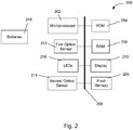
- a number of electronic components described in greater detail with reference to Figure 2 , may be disposed underneath the display window 112.
- the first housing part 104 contains a drug dose setting and delivery mechanism.
- the second housing part 106 contains a drug cartridge 116.
- the drug contained in the drug cartridge 116 may be a medicament of any kind and may preferably be in a liquid form.
- the drug delivery mechanism of the first housing part 104 may be configured to engage with the drug cartridge 116 of the second housing part 106 to facilitate expulsion of the drug.
- the second housing part 106 may be detached from the first housing part 104 in order to insert a drug cartridge 116 or to remove a used cartridge.
- the first and second housing parts 104, 106 may be connected together in any suitable way, for example with a screw or bayonet type connection.
- the first and second housing parts 104, 106 may be non-reversibly connected together is such a way as the drug cartridge 116 is permanently contained with the drug delivery device 100. Further the first and second housing parts 104, 106 may form part of a single housing part.
- the rotatable dial 108 is configured to be rotated by hand by a user of the drug delivery device 100 in order to set a drug dose to be delivered.
- the dial 108 is connected to an internal threading system which causes the dial 108 to be displaced axially from the housing 102 as it is rotated in a first direction.
- the device 100 is configured, once a drug dose has been set by rotation of the rotatable dial 108, to deliver the set drug dose when a user exerts an axial force at the proximal end of the device.
- the rotatable dial 108 may support a button (not shown) which must be depressed in order to deliver the set drug dose.
- the circuitry 200 comprises a microprocessor 202, a non-volatile memory such as a ROM 204, a writable non-volatile memory such as flash memory 205, a volatile memory such as a RAM 206, a display 210, a first optical sensor 212, a second optical sensor 214, LEDs 216 and a bus 208 connecting each of these components.
- the circuitry 200 also comprises batteries 218 or some other suitable source of power for providing power to each of the components.
- the circuitry 200 may be integral with the device 100. Alternatively, the circuitry 200 may be contained within an electronic module that can be attached to the device 100. In addition, the circuitry 200 may comprise additional sensors, such as an optical character recognition (OCR) system or acoustical sensors.
- OCR optical character recognition
- the ROM 204 may be configured to store software and/or firmware. This software/firmware may control operations of the microprocessor 202.
- the microprocessor 202 utilises RAM 206 to execute the software/firmware stored in the ROM to control operation of the display 210. As such the microprocessor 202 may also comprise a display driver.
- the processor 202 utilises the flash memory 205 to store determined amounts of dose dialled and/or determined amounts of dose dispensed, as will be described in more detail below.
- the batteries 218 may provide power for each of the components including the first and second optical sensors 212, 214 and LEDs 216.
- the supply of power to the first and second optical sensors 212, 214 and LEDs 216 may be controlled by the microprocessor 202.
- the microprocessor 202 may receive signals from the first and second optical sensors 212, 214 and is configured to interpret these signals.
- Information may be provided on the display 210 at suitable times by operation of the software/firmware and the microprocessor 202. This information may include measurements determined from the signals received by the microprocessor 202 from the first and second optical sensors 212, 214 such as the drug dose which has been set and/or delivered.
- the display 210 may also show additional information, such as the actual time, the time of the last usage/injection, a remaining battery capacity, one or more warning signs, and/or the like.
- the first and second optical sensors 212, 214 may be configured to capture pixelated greyscale images of printed images or patterns which optically encode information.
- the images or patterns may be printed on movable parts of the drug delivery device 100 which the first and second optical sensors 212, 214 are configured to be directed at.
- the one or more LEDs 216 are also directed at the printed images/patterns in order to provide illumination for the sensors 212, 214.
- the first and second optical sensors 212, 214 may detect the intensity pattern of light reflected from the printed images/patterns.
- the LEDs 216 and sensors 212, 214 may be configured to operate at various wavelengths of light.
- the LEDs 216 and sensors 212, 214 may, for example, operate in infra-red.
- Each of the first and second optical sensors 212, 214 may have an integral LED 216, or the LEDs 216 and sensors 212, 214 may comprise separate units.
- Software stored in the ROM 204 allows the microprocessor 202 to determine from the signals received from the first and second optical sensors 212, 214 whether first and second rotatable components are rotating. Software also allows the microprocessor 202 to analyse and decode images received from the first and second optical sensors 212, 214 and to determine a rotational position of each of the first and second rotatable components.
- the circuitry 200 may comprise further components which are not shown.
- the circuitry 200 may comprise one or more user inputs in the form of hardware or software keys.
- the circuitry 200 may comprise a speaker and/or a microphone.
- the circuitry 200 may also comprise one or more means of removing or communicating information stored in the ROM 204 or flash memory 205, such as a wireless transceiver, a card slot or a cable port (e.g. a USB port).
- Figure 3 is a cross-sectional view of a part of a dose setting mechanism of a drug delivery device 100.
- WO2010/139640 A detailed example of the operation of a dose setting and delivery mechanism supported within the first housing part 104 can be found in published PCT application WO2010/139640 , which is incorporated herein by reference. This document gives details of one particular drug delivery device mechanism. However, the invention may be implemented in a wide variety of different drug delivery devices having different mechanisms.
- the first housing part 104 comprises an outer housing 300, an inner housing 306 and an encoded number sleeve 302. These components are hollow cylinders arranged concentrically.
- the encoded number sleeve 302 is disposed between the inner and outer housings 306, 300.
- the rotatable dial 108 is located at the proximal end of the outer housing 300. Integral with the rotatable dial 108 is a dialling sleeve 304.
- the dialling sleeve 304 comprises a hollow cylinder disposed between the outer housing 300 and the encoded number sleeve 302.
- a recess 114 is provided in the outer housing 300. Electronic components including the display 210 may be received in the recess 114.
- the first optical sensor 212 (also referred to herein as the number sleeve sensor 212) is shown schematically at the position of the recess 114. The number sleeve sensor 212 may be part of the electronic module received in the recess 114, or alternatively may be part of an external device configured to be attached to the drug delivery device 100.
- the second optical sensor 214 (also referred to herein as the dialling sleeve sensor 214) is shown schematically disposed at the proximal end of the outer housing 300. The dialling sleeve sensor 214 may be an integral part of the drug delivery device 100.
- the dialling sleeve sensor may be received in a secondary recess (not shown) or the outer housing 300.
- the dialling sleeve sensor 214 may be part of an external device configured to be attached to the drug delivery device 100. In either case, when in use the dialling sleeve sensor 214 is arranged to be directed at an outer surface of the dialling sleeve 304.
- the outer diameter of the encoded number sleeve 302 may be reduced towards the proximal end of the first housing part 104 in order to provide a space for the dialling sleeve 304.
- the thickness of the outer housing 300 may also be reduced at the proximal end to provide this space.
- the dialling sleeve 304 extends into the first housing part 104 no further than the recess 114 such that when the first optical sensor 212 is positioned at or in the recess 114 it is directed at the encoded number sleeve 302, while the second optical sensor 214 is directed at the dialling sleeve 304.
- the inner housing 306 has a thread 308 provided on a part of its outer surface.
- the encoded number sleeve 302 has a corresponding thread disposed on a part of its inner surface.
- the inner housing 306 is fixed relative to the outer housing 300. Therefore the threaded engagement between the inner housing 306 and the number sleeve 302 causes the number sleeve to move axially relative to the outer housing 300 when rotated (and vice versa).
- the rotatable dial 108 is coupled to the encoded number sleeve 302. This coupling may be provided by a toothed engagement at the proximal end of the encoded number sleeve 302.
- the dial 108 and the encoded number sleeve 302 may be coupled via a third rotatable component.
- the encoded number sleeve 302 also rotates. This causes the rotatable dial 108 and all components coupled thereto to move axially out of the first housing part 104. If the dial 108 is rotated in the opposite direction, it moves back into the first housing part 104.
- a dose After a dose has been dialled into the drug delivery device 100 it may be dispensed by applying an axial load to the distal end of the rotatable dial 108.
- the rotatable dial 108 and integral dialling sleeve 304 are able to move axially relative to the encoded number sleeve 302 when this axial load is applied.
- Biasing means (not shown) may be provided to bias the rotatable dial 108 and the number sleeve 302 apart, i.e. to bias the rotatable dial 108 in the distal direction relative to the number sleeve 302. This position is shown in Figure 3 .
- the rotatable dial moves axially so that the proximal end of the number sleeve 302 enters the space 312 internal to the rotatable dial 108.
- This relative axial movement between the rotatable dial and the number sleeve 302 causes these components to be decoupled.
- the toothed engagement at the proximal end of the encoded number sleeve 302 may be disengaged or a clutch formed by a different part of the mechanism may be disengaged.
- the axial load on the rotatable dial 108 is transferred to other components of the mechanism.
- the axial force is transferred to a spindle 314, disposed centrally within the mechanism, via a drive sleeve 316 in order to cause expulsion of a medicament from the drug cartridge 116.
- the axial force is also transferred to the encoded number sleeve 302 which moves axially back into the first housing part 104. Due to the threaded connection of the encoded number sleeve 302 with the inner housing 306, the number sleeve rotates as it moves axially back into the first housing part 104.
- Figure 4 shows a perspective view of the encoded number sleeve 302 removed from the drug delivery device 100.
- the outer surface of the number sleeve 302 has a helical track 400 comprising a sequence of images. Each of the images encodes information and is designed to be viewed by the number sleeve sensor 212.
- the drug delivery device 100 may be configured to deliver a maximum of 80 units of medicament.
- the track 400 may therefore comprise a series of 81 encoded images encoding positions 0 to 80.
- Figure 5 is a table showing an encoded image scheme which may be used in the present invention. Each of the images in this scheme is comprised of a number of data bits which may be coloured black or white. The images are repeated in the four quadrants of a square.
- the scheme of Figure 5 is merely one example of suitable encoded images.
- the encoded image scheme may instead comprise a series of dot matrix patterns, a series of barcodes or similar or standard Arabic numerals and may comprise a single image per position or multiple repeated images.
- the encoded images may be printed, marked, indented, etched or similar onto the track 400.
- the encoded number sleeve 302 is arranged within the mechanism such that when no dose is dialled into the drug delivery device 100 the first encoded image (encoding position "0") is located directly underneath the recess 114. This allows the encoded image to be viewed by the first optical sensor 212.
- the pitch of the track 400 is the same as the threads on the encoded number sleeve 302 and inner housing 306 such that as the number sleeve 302 rotates and moves axially out of the first housing part 104 the track 400 remains located underneath the recess 114 in the outer housing 300.
- the first optical sensor 212 is configured to capture the images and to relay signals to the microprocessor 202.
- One or more LEDs 216 may illuminate the track 400 to allow the first optical sensor 212 to capture images.
- the microprocessor 202 is configured to employ software stored in the ROM 204 to determine the content of each image, for example which parts of the image are black and which parts are white, and to identify a corresponding rotational position of the encoded number sleeve 302 relative to the sensor 212.
- the microprocessor 202 may achieve this by consulting a table stored in the ROM 204 which relates the content of each image to a rotational position of the number sleeve 302 and hence to a drug dose which has been dialled.
- Figure 6 is a plan view of the dialling sleeve 304 removed from the drug delivery device 100.
- the dialling sleeve 304 may be formed integrally with the rotatable dial 108, or maybe fixed to the rotatable dial 108.
- An incremental optical code is marked on an outer surface of the dialling sleeve 304.
- the incremental code comprises alternating black bands 600 and white bands 602 extending axially.
- the black bands 600 may be printed onto the dialling sleeve 304, which is white.
- the white bands 602 may also be printed.
- any markings which allow rotation of the dialling sleeve 304 to be detected by the second optical sensor 214 may be used, such as a series of equally spaced marks.
- the surface of the dialling sleeve 304 may be a smooth cylinder, or may be corrugated. The corrugations may form the incremental markings.
- the dialling sleeve 304 may have a textured surface with well defined parameters allowing rotation of the dialling sleeve 304 to be detected.
- a user grasps and twists the rotatable dial 108.
- the rotatable dial 108 is coupled to the encoded number sleeve 302, which therefore also rotates.
- the threaded connection between the encoded number sleeve 302 and the inner housing 306 causes the number sleeve 302 and dialling sleeve 304 to move axially out of the first housing part 104.
- the movement of the encoded number sleeve 302 and dialling sleeve 304 describes a helix.
- the first optical sensor 212 is part of an electronics module received in the recess 114 in the outer housing 300. In other embodiments, the first optical sensor 212 is installed on the inner surface of the outer housing 300 during manufacture. The first optical sensor 212 may be connected to the other electronic components via conductive tracks running along and/or through the outer housing 300. In some other embodiments, the first optical sensor 212 is part of a supplemental device configured to be releasably attached to the drug delivery device 100. The first optical sensor 212 is configured to be directed at the encoded number sleeve 302 so as to view the encoded images of the track 400. One or more LEDs 216 are configured to illuminate the track 400. Images may be captured by the first optical sensor 212 at periodic intervals, for example twice per second. The images captured by the first optical sensor 212 are relayed to the microprocessor 202 for decoding.
- the dialling sleeve 304 moves helically, it is viewed by the second optical sensor 214.
- One or more LEDs 216 are configured to illuminate the surface of the dialling sleeve 304.
- the second optical sensor 214 observes alternating black and white stripes as the dialling sleeve 304 rotates.
- the second optical sensor 214 may capture images at predetermined intervals. The interval may be the same as or different to that of the first optical sensor 212.
- the images captured by the second optical sensor 214 are relayed to the microprocessor 202 for analysis.
- conductive tracks may pass through the outer housing 300 or be printed onto an inner surface of the outer housing 300 to transmit signals to and from the sensor 214.
- the angular width of the black and white bands 600, 602 is predetermined.
- the surface of the dialling sleeve 304 may comprise 12 white bands 602 and 12 black bands 600.
- the microprocessor 202 can therefore use the received image signals to determine incrementally the amount of rotation (in either direction) of the dialling sleeve 304.
- each of the first and second optical sensors 212, 214 may be different.
- the field of view of the first optical sensor 212 must be large enough to encompass the whole of each encoded image in order for the image to be successfully decoded.
- the second optical sensor 214 only needs to determine whether the dialling sleeve 304 is rotating or not, so the field of view should preferably be no wider than the width of the black and white bands 600, 602.
- Figure 7 shows the proximal end of a different drug delivery device 700 in which the invention may be used.
- Figure 7 shows both an end view (left) and a plan view (right) of the proximal end of the drug delivery device 700.
- the device 700 comprises the same first and second housing parts 104, 106, with the first housing part 104 containing the drug dose setting and delivery mechanism and the second housing part (not visible in Figure 7 ) containing a drug cartridge.
- the device 700 also has a rotatable dial 702 (also referred to herein as a dose selector) similar or identical to that previously described.
- the drug dose setting and delivery mechanism of the device 700 shown in Figure 7 is constructed such that when the rotatable dial 702 is rotated to set a dose, it does not move axially out of the housing 104, but only rotates. This may be achieved by providing a drive spring which stores energy when the rotatable dial 702 is rotated.
- a cylindrical compression/tension or torsion spring is suitable for this purpose as it can be easily incorporated into the cylindrical body of the device 700.
- the rotatable dial 702 may house a dose delivery button which is depressed in order to dispense a dose, or alternatively the whole rotatable dial 702 may be depressed axially in order to dispense a dose.
- the drug delivery device 700 also has a clutch mechanism which disengages the rotatable dial 702 from the drive spring when this axial load is applied allowing the drive spring to return to its original position without rotation of the rotatable dial 702. In returning to its original position, the drive spring forces a spindle to advance into the drug cartridge and thereby cause expulsion of a medicament from the drug cartridge.
- the encoded number sleeve (not visible in Figure 7 ) is in mechanical communication with the drive spring and moves axially when energy is stored in or released from the drive spring.
- the encoded number sleeve moves in a first longitudinal direction when a dose is dialed into the drug delivery device 700 and in a second (opposite) longitudinal direction when a dose is dialed out of the drug delivery device 700 or when a dose is dispensed form the drug delivery device 700.
- the encoded number sleeve need not be a hollow cylinder as in the previously described embodiments, as it does not rotate, but only moves longitudinally.
- the encoded images or numbers are printed in a longitudinal line on the encoded number sleeve such that they pass through the field of view of the first optical sensor 212.
- the drug delivery device 700 also comprises a sensor arm 704 which extends from the first housing part 104 such that it is adjacent to the rotatable dial 702.
- the second optical sensor 214 is housed within this sensor arm 704 and directed at the rotatable dial 702.
- the sensor arm 704 and second optical sensor 214 may be part of an external device configured to be attached to the drug delivery device 100.
- the second optical sensor 214 is configured to observe the rotation of the rotatable dial 702 directly. This removes the need to have a second window allowing the dialing sleeve to be visible to the second optical sensor 214 and the need for any modification of the dialing sleeve.
- the rotatable dial 702 has a corrugated surface to aid in gripping and turning the dial.
- the corrugations on the rotatable dial 702 may be coloured or shaded to allow the second optical sensor 214 to detect rotation of the dial 702.
- the angular width of the corrugations may be known, such that the amount of rotation can also be determined form the signals produced by the second optical sensor 214.
- the second optical sensor 214 detects whether the rotatable dial 702 is rotating or stationary.
- the second optical sensor 214 may be replaced by another type of sensor, for example a proximity sensor which detects the changes in surface height of the dial 702 or a capacitive or hall sensor.
- a user grasps and twists the rotatable dial 702 to set a dose.
- the rotatable dial 702 rotates, but does not move axially.
- the rotatable dial 702 is coupled to a drive spring which stores energy as the dial is rotated. This in turn also causes the encoded number sleeve to move in a first longitudinal direction. As the number sleeve moves longitudinally, it is viewed by the first optical sensor 212.
- the first optical sensor 212 is part of an electronics module received in the recess 114 in the first housing part 104. In other embodiments, the first optical sensor 212 is installed on the inner surface of the first housing part 104 during manufacture.
- the first optical sensor 212 may be connected to the other electronic components via conductive tracks running along and/or through the housing. In some other embodiments, the first optical sensor 212 is part of a supplemental device configured to be releasably attached to the drug delivery device 700.
- the second optical sensor 214 As the rotatable dial 702 moves longitudinally, it is viewed by the second optical sensor 214.
- One or more LEDs 216 may be provided and configured to illuminate the surface of the rotatable dial 702.
- the second optical sensor 214 may rely on ambient light or may be another type of sensor as previously described.
- the corrugations of the rotatable dial 702 form alternating black and white bands.
- the second optical sensor 214 observes these alternating black and white bands as the rotatable dial 702 rotates.
- the second optical sensor 214 may capture images at predetermined intervals. The interval may be the same as or different to that of the first optical sensor 212.
- the images captured by the second optical sensor 214 are relayed to the microprocessor 202 for analysis.
- Conductive tracks may pass through the housing or be printed onto an inner surface of the housing to transmit signals to and from the sensor 214.
- the processor 202 receives signals from the first and second sensors 212, 214 and determines whether the drug delivery device 700 is in a drug dose dialling mode or a drug dose delivery mode.
- the processor may use the signals from the sensor to distinguish three different situations.
- an activation switch 800 is shown. Although this feature is described with reference to the first type of drug delivery device 100, it is equally applicable to the second type of drug delivery device 700 described with reference to Figure 7 .
- the first and second optical sensors 212, 214 and LEDs 216 may be activated by rotation of the dial 108. This may be achieved by a switch 800 which is triggered whenever the dial 108 is rotated away from the zero dose position.
- the switch 800 may be comprised of an electromechanical switch having a protrusion 802.
- the protrusion 802 may be biased towards a protruding position.
- the protrusion 802 passes through a recess in the outer body 300, which may be part of the recess 114.
- the proximal end of the dialling sleeve 304 may be configured to contact the protrusion 802 when the drug delivery device 100 is in the zero dose position, as shown in Figure 8 .
- the dialling sleeve 304 moves axially.
- the protrusion 802 can then enter the space left by the dialling sleeve 304. This movement changes the state of the switch 800.
- the protrusion 802 may contact the outer surface of the encoded number sleeve 302.
- a recess may be cut into the outer surface of the encoded number sleeve 302 and the protrusion enters this recess when the sleeve 302 is in the zero dose position.
- the recess and/or the protrusion 802 may have sloped edges to allow the protrusion 802 to slide out of the recess when the sleeve 302 is rotated.
- the state change of the switch 800 may be used as the trigger to activate the first and second optical sensors 212, 214 and LEDs 216.
- the drug delivery device 100 (or supplemental device in some embodiments) may remain in a standby or sleep mode until the switch 800 changes state.
- the first and second optical sensors 212, 214 and LEDs 216 are components which consume power while active. Optical sensors may also have relatively high standby current requirements.
- the drug delivery device 100 (or supplemental device in some embodiments) is portable and the batteries 218 have a limited capacity. The battery life of the drug delivery device 100 is therefore conserved by activating these components only at the required time.
- the first and second optical sensors 212, 214 and LEDs 216 may be deactivated when the drug delivery device 100 is returned to the zero dose position, or after a predetermined time delay after the delivery device 100 is returned to the zero dose position.
- software stored in the ROM 204 also allows the microprocessor 202 to use the signals received from the first and second optical sensors 212, 214 to determine a mode of operation of the drug delivery device 100.
- the dial 108 is rotated to dial a dose into or out of the device 100.
- This causes both the encoded number sleeve 302 and dialling sleeve 304 to move helically, as previously described.
- the first optical sensor 212 views the encoded images on the track 400 passing in sequence. Each of these images encodes a unique rotational position, allowing the currently dialled dose to be determined.
- the second optical sensor 214 views the alternating black and white bands 600, 602 as they rotate past. As both sensors view helical motion, it is determined that the drug delivery device 100 is in a dialling mode. While the drug delivery device 100 is in the dialling mode, the output from the number sleeve sensor 212 can be used by the microprocessor to determine the value of the current dialled dose. This value can be displayed on the display 210.
- the drug delivery device 100 When an axial load is applied to the rotatable dial 108, the drug delivery device 100 is in a "dispensing mode".
- the rotatable dial 108 and dialling sleeve 304 are de-coupled from the encoded number sleeve 302, as previously described.
- the encoded number sleeve 302 translates back into the first housing part 104, it moves in the same helical way as in the dialling mode.
- the rotatable dial 108 and dialling sleeve 304 translate only and do not rotate.
- the first optical sensor 212 views the encoded images on the track 400 passing in sequence, but the second optical sensor 214 views no change in the incremental encoded images on the dialling sleeve 304 and no change in the output of the second optical sensor 214 results.
- the microprocessor 202 can thus determine that the drug delivery device 100 is in a dispensing mode. While the drug delivery device 100 is in the dispensing mode, the output from the number sleeve sensor 212 can be used by the microprocessor to determine the value of an injected dose. This value can be displayed on the display 210 and stored in the flash memory 205. Results of previous dispensing action may be later recalled from the flash memory 205 and displayed on the display 210.
- the drug delivery device 100 Being able to determine the mode of operation of the drug delivery device 100 is advantageous, as the drug delivery device 100 (or the attached supplemental device) is able to calculate electronically the dose of medicament which has been delivered. For example, a user may dial in a dose but then dial some of the dose out before dispensing the remaining dose. Alternatively, a user may deliver only a part of a dose and may dial the remaining dose out. It is important to accurately record the dose of medicament which has actually been delivered in order to accurately assess the effect of the medicament on the user's health and for the calculation of future medicament doses.
Landscapes
- Health & Medical Sciences (AREA)
- Engineering & Computer Science (AREA)
- General Health & Medical Sciences (AREA)
- Vascular Medicine (AREA)
- Animal Behavior & Ethology (AREA)
- Veterinary Medicine (AREA)
- Public Health (AREA)
- Life Sciences & Earth Sciences (AREA)
- Hematology (AREA)
- Heart & Thoracic Surgery (AREA)
- Biomedical Technology (AREA)
- Anesthesiology (AREA)
- Physics & Mathematics (AREA)
- Electromagnetism (AREA)
- Theoretical Computer Science (AREA)
- General Physics & Mathematics (AREA)
- Computer Vision & Pattern Recognition (AREA)
- Toxicology (AREA)
- Artificial Intelligence (AREA)
- Infusion, Injection, And Reservoir Apparatuses (AREA)
Claims (13)
- Zusatzvorrichtung, die zur Befestigung an einer Medikamenten-Verabreichungsvorrichtung (100) konfiguriert ist, wobei die Zusatzvorrichtung ein optisches Decodiersystem umfasst, umfassend:einen ersten optischen Sensor (212), der zum Ausrichten auf eine erste drehbare Komponente der Medikamenten-Verabreichungsvorrichtung konfiguriert ist;einen zweiten optischen Sensor (214), der zum Ausrichten auf eine zweite drehbare Komponente der Medikamenten-Verabreichungsvorrichtung konfiguriert ist; undeinen Prozessor (202), der zu Folgendem konfiguriert ist:Empfangen von Signalen von dem ersten optischen Sensor (212), wobei die Signale von dem ersten optischen Sensor (212) codierte Dosierungswerte darstellen, die an der ersten drehbaren Komponente vorliegen und unabhängig davon, ob sich die erste drehbare Komponente dreht oder nicht;Empfangen von Signalen von dem zweiten optischen Sensor (214), wobei die Signale von dem zweiten optischen Sensor (214) darstellen, ob sich die zweite drehbare Komponente dreht oder nicht; und zum Bestimmen:i) dass sich die Medikamenten-Verabreichungsvorrichtung in einem Medikamenten-Dosiseinstellmodus befindet, wenn die von dem ersten optischen Sensor (212) empfangenen Signale darauf hinweisen, dass sich die erste drehbare Komponente dreht, und die von dem zweiten optischen Sensor (214) empfangenen Signale darauf hinweisen, dass sich die zweite drehbare Komponente dreht, undii) dass sich die Vorrichtung in einem Medikamenten-Dosisverabreichungsmodus befindet, wenn die von dem ersten Sensor (212) empfangenen Signale darauf hinweisen, dass sich die erste drehbare Komponente dreht, und die von dem zweiten Sensor (214) empfangenen Signale darauf hinweisen, dass sich die zweite drehbare Komponente nicht dreht.
- Zusatzvorrichtung nach Anspruch 1, wobei der Prozessor (202) ferner zum Empfangen von Signalen von dem ersten optischen Sensor (212) konfiguriert ist, die darstellen, ob sich die erste drehbare Komponente axial in einer ersten Längsrichtung oder axial in einer zweiten Längsrichtung, die der ersten Längsrichtung entgegengesetzt ist, bewegt.
- Zusatzvorrichtung nach Anspruch 2, wobei der Prozessor ferner zum Bestimmen konfiguriert ist, dass eine Dosis in der Medikamenten-Verabreichungsvorrichtung eingestellt wird, wenn die von dem ersten optischen Sensor (212) empfangenen Signale darauf hinweisen, dass sich die erste drehbare Komponente in der ersten Längsrichtung bewegt, und die von dem zweiten optischen Sensor (214) empfangenen Signale darauf hinweisen, dass sich die zweite drehbare Komponente dreht.
- Zusatzvorrichtung nach Anspruch 2 oder Anspruch 3, wobei der Prozessor (202) ferner zum Bestimmen konfiguriert ist, dass eine Dosis in der Medikamenten-Verabreichungsvorrichtung ausgewählt wird, wenn die von dem ersten optischen Sensor (212) empfangenen Signale darauf hinweisen, dass sich die erste drehbare Komponente in der zweiten Längsrichtung bewegt, und die von dem zweiten optischen Sensor (214) empfangenen Signale darauf hinweisen, dass sich die zweite drehbare Komponente dreht.
- Zusatzvorrichtung nach einem der Ansprüche 2 bis 4, wobei der Prozessor ferner zum Bestimmen konfiguriert ist, dass eine Dosis aus der Medikamenten-Verabreichungsvorrichtung (100) ausgeworfen wird, wenn die von dem ersten optischen Sensor (212) empfangenen Signale darauf hinweisen, dass sich die erste drehbare Komponente in der zweiten Längsrichtung bewegt, und die von dem zweiten optischen Sensor (214) empfangenen Signale darauf hinweisen, dass sich die zweite drehbare Komponente nicht dreht.
- Zusatzvorrichtung nach Anspruch 1, wobei der Prozessor ferner zum Bestimmen einer Medikamentendosis, die verabreicht wurde, und zum Veranlassen des Speicherns einer Aufzeichnung der verabreichten Dosis in einem Speicher (205) konfiguriert ist.
- Zusatzvorrichtung nach Anspruch 1, wobei das optische Decodiersystem ferner eine Anzeigevorrichtung (210) umfasst und wobei der Prozessor (202) zum Veranlassen der Anzeigevorrichtung (210) zum Anzeigen einer Angabe der Medikamentendosis, die verabreicht wurde, konfiguriert ist.
- Zusatzvorrichtung nach einem der Ansprüche 1 bis 7, wobei das optische Decodiersystem ferner eine oder mehrere LEDs (216) umfasst, die zum Beleuchten von Abschnitten der ersten und/oder zweiten drehbaren Komponente konfiguriert sind.
- Zusatzvorrichtung nach einem der Ansprüche 1 bis 8, wobei das optische Decodiersystem ferner einen Schalter (800) umfasst und wobei eine Änderung im Zustand des Schalters (800) zum Veranlassen der Aktivierung des ersten und zweiten optischen Sensors (212, 214) konfiguriert ist.
- Zusatzvorrichtung nach Anspruch 9, wobei der Schalter (800) derart konfiguriert ist, dass sich der Zustand des Schalters (800) ändert, wenn sich die Medikamenten-Verabreichungsvorrichtung (100) von einer Null-Einheit-Medikamentendosis-Anordnung zu einer Einzel-Einheit-Medikamentendosis-Anordnung bewegt.
- Zusatzvorrichtung nach Anspruch 9 oder Anspruch 10, wobei die Zusatzvorrichtung zum Verbleiben in einem Standby- oder Ruhemodus, bis sich der Zustand des Schalters (800) ändert, konfiguriert ist.
- Zusatzvorrichtung nach einem der vorhergehenden Ansprüche, wobei der erste optische Sensor (212) und der zweite optische Sensor (214) zum Erfassen von verpixelten Grauskala-Bildern von gedruckten Bildern oder Mustern, die optisch Informationen kodieren, konfiguriert sind.
- Zusatzvorrichtung nach Anspruch 12, wobei die Zusatzvorrichtung ferner einen nichtflüchtigen Speicher (204) umfasst und wobei der Prozessor (202) zum Konsultieren einer im nichtflüchtigen Speicher (204) gespeicherten Tabelle, die sich auf den Inhalt jedes Bildes oder Musters bezieht, konfiguriert ist.
Applications Claiming Priority (3)
| Application Number | Priority Date | Filing Date | Title |
|---|---|---|---|
| EP13151370 | 2013-01-15 | ||
| EP14700464.2A EP2945665B1 (de) | 2013-01-15 | 2014-01-13 | Stiftartiger arzneimittelinjektor mit optischem dosisdecodiersystem sowie sensor zur unterscheidung von dosiseinstell- und dosisabgabemodus |
| PCT/EP2014/050467 WO2014111340A1 (en) | 2013-01-15 | 2014-01-13 | Pen-type drug injection device and optical dose value decoding system with additional sensor to distinguish between dose dialling and dose delivery mode |
Related Parent Applications (1)
| Application Number | Title | Priority Date | Filing Date |
|---|---|---|---|
| EP14700464.2A Division EP2945665B1 (de) | 2013-01-15 | 2014-01-13 | Stiftartiger arzneimittelinjektor mit optischem dosisdecodiersystem sowie sensor zur unterscheidung von dosiseinstell- und dosisabgabemodus |
Publications (3)
| Publication Number | Publication Date |
|---|---|
| EP3369446A2 EP3369446A2 (de) | 2018-09-05 |
| EP3369446A3 EP3369446A3 (de) | 2018-09-19 |
| EP3369446B1 true EP3369446B1 (de) | 2021-09-01 |
Family
ID=47681660
Family Applications (2)
| Application Number | Title | Priority Date | Filing Date |
|---|---|---|---|
| EP14700464.2A Active EP2945665B1 (de) | 2013-01-15 | 2014-01-13 | Stiftartiger arzneimittelinjektor mit optischem dosisdecodiersystem sowie sensor zur unterscheidung von dosiseinstell- und dosisabgabemodus |
| EP18154250.7A Active EP3369446B1 (de) | 2013-01-15 | 2014-01-13 | System zur optischen decodierung für eine arzneimittelabgabevorrichtung |
Family Applications Before (1)
| Application Number | Title | Priority Date | Filing Date |
|---|---|---|---|
| EP14700464.2A Active EP2945665B1 (de) | 2013-01-15 | 2014-01-13 | Stiftartiger arzneimittelinjektor mit optischem dosisdecodiersystem sowie sensor zur unterscheidung von dosiseinstell- und dosisabgabemodus |
Country Status (7)
| Country | Link |
|---|---|
| US (2) | US9764095B2 (de) |
| EP (2) | EP2945665B1 (de) |
| JP (1) | JP6316312B2 (de) |
| CN (2) | CN109381776B (de) |
| DK (1) | DK2945665T3 (de) |
| TR (1) | TR201807770T4 (de) |
| WO (1) | WO2014111340A1 (de) |
Families Citing this family (45)
| Publication number | Priority date | Publication date | Assignee | Title |
|---|---|---|---|---|
| EP2945668B1 (de) | 2013-01-15 | 2018-05-23 | Sanofi-Aventis Deutschland GmbH | Vorrichtung zur aufzeichnung von informationen in form von digitalen bildern betreffend die verwendung einer medizinischen injektionsvorrichtung |
| BR112015026440A2 (pt) * | 2013-04-22 | 2017-07-25 | Sanofi Aventis Deutschland | dispositivo suplementar para fixação a um dispositivo de injeção |
| US10569028B2 (en) | 2014-11-05 | 2020-02-25 | Insuline Medical Ltd. | Drug tracking device |
| EP3045186A1 (de) | 2015-01-16 | 2016-07-20 | Sanofi-Aventis Deutschland GmbH | Sensor zur Verwendung mit einer Arzneimittelverabreichungsvorrichtung |
| JP7055019B2 (ja) | 2015-01-21 | 2022-04-15 | サノフィ-アベンティス・ドイチュラント・ゲゼルシャフト・ミット・ベシュレンクテル・ハフツング | ペン型注射器に取り付け、光学式インクリメンタルエンコーダ(incremental encoder)を用いて設定用量を決定するための補助デバイス |
| EP3067081A1 (de) * | 2015-03-12 | 2016-09-14 | Sanofi | Arzneimittelabgabevorrichtung |
| EP3374009B1 (de) * | 2015-11-11 | 2021-01-06 | Novo Nordisk A/S | Arzneimittelausgabevorrichtung mit informationserfassung |
| EP3178507A1 (de) | 2015-12-09 | 2017-06-14 | Carebay Europe Ltd. | Kommunikationsvorrichtung zur übertragung von informationen von einer medikamentenabgabevorrichtung |
| TW201731543A (zh) * | 2015-12-10 | 2017-09-16 | 賽諾菲阿凡提斯德意志有限公司 | 可移除地附接於藥物輸送裝置之感測裝置 |
| CN108697857B (zh) * | 2015-12-10 | 2021-06-18 | 赛诺菲-安万特德国有限公司 | 具有可移除地附接的传感器装置的药物输送装置 |
| WO2017118705A1 (en) * | 2016-01-06 | 2017-07-13 | Sanofi-Aventis Deutschland Gmbh | Medicament delivery device |
| US10864327B2 (en) | 2016-01-29 | 2020-12-15 | Companion Medical, Inc. | Automatic medication delivery tracking |
| WO2017148857A1 (en) | 2016-03-01 | 2017-09-08 | Novo Nordisk A/S | Power efficient accessory device |
| JP6543775B2 (ja) * | 2016-03-25 | 2019-07-10 | イーライ リリー アンド カンパニー | 薬剤送達装置における設定及び送達された用量の判定 |
| CN113101462A (zh) * | 2016-05-24 | 2021-07-13 | 赛诺菲-安万特德国有限公司 | 附接于药物输送装置的补充装置、药物输送装置的数字套筒和药物输送装置 |
| EP4029547B1 (de) | 2016-07-15 | 2026-03-11 | Eli Lilly and Company | Dosiserfassungsmodul für eine arzneimittelabgabevorrichtung |
| CN107754058B (zh) * | 2016-08-18 | 2022-03-04 | 广东东阳光药业有限公司 | 一种注射器用数据采集方法、数据采集结构及注射器 |
| ES2871883T3 (es) * | 2016-09-09 | 2021-11-02 | Sanofi Aventis Deutschland | Aparato de recopilación de datos para su fijación a un dispositivo de inyección |
| WO2018046660A1 (en) * | 2016-09-09 | 2018-03-15 | Sanofi-Aventis Deutschland Gmbh | Reading device, drug delivery device and drug delivery device in combination with a reading device |
| CN108066850A (zh) * | 2016-11-15 | 2018-05-25 | 广东东阳光药业有限公司 | 一种自动采集刻度数据的注射器 |
| LT3589340T (lt) | 2017-02-28 | 2026-01-12 | Eli Lilly And Company | Vaistų leidimo įrenginio dozės aptikimas ir vaistų identifikavimas |
| JP7042838B2 (ja) * | 2017-03-15 | 2022-03-28 | ノボ・ノルデイスク・エー/エス | 二次画像分析機能を有する用量捕捉アセンブリ |
| EP4101485B1 (de) | 2017-08-21 | 2025-12-10 | Eli Lilly and Company | Medikamentenabgabevorrichtung mit erfassungssystem |
| WO2019040117A1 (en) | 2017-08-21 | 2019-02-28 | Eli Lilly And Company | DOSE DETECTION MODULE FOR DRUG DELIVERY DEVICE |
| DE102017215035A1 (de) | 2017-08-29 | 2019-02-28 | Robert Bosch Gmbh | Injektionsvorrichtung sowie entsprechendes Injektionsmessverfahren |
| EP3710082A1 (de) * | 2017-11-14 | 2020-09-23 | Sanofi | Drahtlose elektronikbaugruppe für injektionsvorrichtungen |
| WO2019101962A1 (en) | 2017-11-23 | 2019-05-31 | Sanofi | Medicament injection device with rotary encoder |
| US10987464B2 (en) | 2017-12-12 | 2021-04-27 | Bigfoot Biomedical, Inc. | Pen cap for insulin injection pens and associated methods and systems |
| JP7512203B2 (ja) | 2017-12-12 | 2024-07-08 | ビッグフット バイオメディカル インコーポレイテッド | 治療支援情報及び/又は追跡装置並びに関連する方法及びシステム |
| US11083852B2 (en) | 2017-12-12 | 2021-08-10 | Bigfoot Biomedical, Inc. | Insulin injection assistance systems, methods, and devices |
| US11464459B2 (en) | 2017-12-12 | 2022-10-11 | Bigfoot Biomedical, Inc. | User interface for diabetes management systems including flash glucose monitor |
| US11077243B2 (en) | 2017-12-12 | 2021-08-03 | Bigfoot Biomedical, Inc. | Devices, systems, and methods for estimating active medication from injections |
| US11197964B2 (en) | 2017-12-12 | 2021-12-14 | Bigfoot Biomedical, Inc. | Pen cap for medication injection pen having temperature sensor |
| US11116899B2 (en) | 2017-12-12 | 2021-09-14 | Bigfoot Biomedical, Inc. | User interface for diabetes management systems and devices |
| WO2019129619A1 (en) | 2017-12-28 | 2019-07-04 | Sanofi | A sensor device for attachment to an injection device |
| DK3755403T3 (da) | 2018-02-22 | 2024-09-23 | Lilly Co Eli | Medikamenttilførselsanordning med et registreret element |
| DE102018203470A1 (de) | 2018-03-08 | 2019-03-07 | Robert Bosch Gmbh | Injektionsvorrichtung sowie entsprechendes Injektionsmessverfahren |
| WO2019219825A1 (en) | 2018-05-18 | 2019-11-21 | Novo Nordisk A/S | Drug delivery assembly with information capture |
| US12205699B1 (en) | 2018-10-30 | 2025-01-21 | Bigfoot Biomedical, Inc. | Method of pairing therapy devices using shared secrets, and related systems, methods and devices |
| EA039601B1 (ru) * | 2018-12-14 | 2022-02-15 | Эли Лилли Энд Компани | Модуль системы определения дозы для устройства доставки лекарственного препарата |
| EA202192026A1 (ru) | 2019-02-27 | 2021-11-12 | Эли Лилли Энд Компани | Устройство для доставки лекарственного препарата с измерительной системой |
| US11948671B2 (en) | 2019-04-11 | 2024-04-02 | Medtronic Minimed, Inc. | Intelligent accessories for medicine dispensing device |
| WO2023036719A1 (en) * | 2021-09-07 | 2023-03-16 | Sanofi | Injection device and supplementary device |
| US20240390597A1 (en) * | 2021-09-24 | 2024-11-28 | Sanofi | Measurement System for a Drug Delivery Device, Drug Delivery Device with Such a Measurement System and Method for Measuring the Dose Dispensed and/or Dose set of a drug delivery device |
| EP4520365A1 (de) * | 2023-09-05 | 2025-03-12 | Ypsomed AG | Zusatzmodul für eine injektionsvorrichtung |
Family Cites Families (11)
| Publication number | Priority date | Publication date | Assignee | Title |
|---|---|---|---|---|
| US4919650A (en) * | 1987-03-30 | 1990-04-24 | Bionica Pty. Limited | Infusion pump |
| DE10330985A1 (de) * | 2003-07-09 | 2005-02-17 | Tecpharma Licensing Ag | Vorrichtung zur Verabreichung eines fluiden Produkts mit optischer Abtastung |
| WO2006001816A1 (en) | 2004-06-14 | 2006-01-05 | Varec, Inc. | Method and system for encoding fluid level |
| JP5562969B2 (ja) * | 2008-11-06 | 2014-07-30 | ノボ・ノルデイスク・エー/エス | 電子的に支援された薬剤送達装置 |
| CN104888316B (zh) | 2009-02-27 | 2017-08-08 | 生命扫描有限公司 | 给药系统 |
| US10034982B2 (en) | 2009-06-01 | 2018-07-31 | Sanofi-Aventis Deutschland Gmbh | Spindle for a drug delivery device |
| TW201808357A (zh) * | 2010-03-22 | 2018-03-16 | 賽諾菲阿凡提斯德意志有限公司 | 用於判定與醫療裝置有關的資訊之裝置、方法、系統及電腦程式 |
| KR101939267B1 (ko) * | 2010-07-21 | 2019-01-16 | 삼성전자주식회사 | 주사기의 주사량 측정 장치 및 방법 |
| CA2808469A1 (en) | 2010-08-19 | 2012-02-23 | Sanofi-Aventis Deutschland Gmbh | Method and system for determining information related to a drug reservoir using an electronic sensor |
| EP2696918A2 (de) * | 2011-04-11 | 2014-02-19 | Novo Nordisk A/S | Injektionsvorrichtung mit dosisüberwachung |
| JP6106666B2 (ja) * | 2011-07-07 | 2017-04-05 | ノボ・ノルデイスク・エー/エス | アドオン式の投薬取得/表示モジュールを備える薬剤送出注射ペン |
-
2014
- 2014-01-13 EP EP14700464.2A patent/EP2945665B1/de active Active
- 2014-01-13 CN CN201811167383.6A patent/CN109381776B/zh active Active
- 2014-01-13 WO PCT/EP2014/050467 patent/WO2014111340A1/en not_active Ceased
- 2014-01-13 US US14/760,691 patent/US9764095B2/en active Active
- 2014-01-13 EP EP18154250.7A patent/EP3369446B1/de active Active
- 2014-01-13 DK DK14700464.2T patent/DK2945665T3/en active
- 2014-01-13 TR TR2018/07770T patent/TR201807770T4/tr unknown
- 2014-01-13 CN CN201480004400.8A patent/CN104902944B/zh active Active
- 2014-01-13 JP JP2015552073A patent/JP6316312B2/ja active Active
-
2017
- 2017-08-21 US US15/681,789 patent/US10532160B2/en active Active
Also Published As
| Publication number | Publication date |
|---|---|
| JP6316312B2 (ja) | 2018-04-25 |
| EP3369446A2 (de) | 2018-09-05 |
| US20160015902A1 (en) | 2016-01-21 |
| CN104902944B (zh) | 2018-10-26 |
| HK1211511A1 (en) | 2016-05-27 |
| TR201807770T4 (tr) | 2018-06-21 |
| EP2945665A1 (de) | 2015-11-25 |
| US9764095B2 (en) | 2017-09-19 |
| WO2014111340A1 (en) | 2014-07-24 |
| DK2945665T3 (en) | 2018-06-14 |
| JP2016502899A (ja) | 2016-02-01 |
| US20170340826A1 (en) | 2017-11-30 |
| EP2945665B1 (de) | 2018-03-07 |
| CN109381776B (zh) | 2021-10-26 |
| CN109381776A (zh) | 2019-02-26 |
| CN104902944A (zh) | 2015-09-09 |
| EP3369446A3 (de) | 2018-09-19 |
| US10532160B2 (en) | 2020-01-14 |
| HK1256894A1 (en) | 2019-10-04 |
Similar Documents
| Publication | Publication Date | Title |
|---|---|---|
| EP3369446B1 (de) | System zur optischen decodierung für eine arzneimittelabgabevorrichtung | |
| US11213629B2 (en) | Sensor for use with a drug delivery device | |
| EP2945673B1 (de) | Dekodiersystem | |
| EP3248637B1 (de) | Optisches dosisdekodierverfahren | |
| HK1256894B (en) | Pen-type drug injection device and optical dose value decoding system with additional sensor to distinguish between dose dialling and dose delivery mode | |
| HK1211511B (en) | Pen-type drug injection device and optical dose value decoding system with additional sensor to distinguish between dose dialling and dose delivery mode | |
| HK1247142B (en) | Optical dose decoding method | |
| HK1211512B (en) | Pen-type drug injection device with optical dose encoding and decoding system | |
| HK40063308A (en) | Sensor for use with a drug delivery device | |
| HK1246703B (en) | Sensor for use with a drug delivery device | |
| HK1211510B (en) | A decoding system |
Legal Events
| Date | Code | Title | Description |
|---|---|---|---|
| PUAI | Public reference made under article 153(3) epc to a published international application that has entered the european phase |
Free format text: ORIGINAL CODE: 0009012 |
|
| STAA | Information on the status of an ep patent application or granted ep patent |
Free format text: STATUS: THE APPLICATION HAS BEEN PUBLISHED |
|
| PUAL | Search report despatched |
Free format text: ORIGINAL CODE: 0009013 |
|
| AC | Divisional application: reference to earlier application |
Ref document number: 2945665 Country of ref document: EP Kind code of ref document: P |
|
| AK | Designated contracting states |
Kind code of ref document: A2 Designated state(s): AL AT BE BG CH CY CZ DE DK EE ES FI FR GB GR HR HU IE IS IT LI LT LU LV MC MK MT NL NO PL PT RO RS SE SI SK SM TR |
|
| AK | Designated contracting states |
Kind code of ref document: A3 Designated state(s): AL AT BE BG CH CY CZ DE DK EE ES FI FR GB GR HR HU IE IS IT LI LT LU LV MC MK MT NL NO PL PT RO RS SE SI SK SM TR |
|
| RIC1 | Information provided on ipc code assigned before grant |
Ipc: A61M 5/315 20060101ALN20180813BHEP Ipc: A61M 5/20 20060101AFI20180813BHEP Ipc: G01D 5/26 20060101ALI20180813BHEP Ipc: G01D 5/347 20060101ALI20180813BHEP Ipc: G06F 19/00 20180101ALI20180813BHEP Ipc: G06K 7/10 20060101ALI20180813BHEP Ipc: A61M 5/24 20060101ALN20180813BHEP |
|
| STAA | Information on the status of an ep patent application or granted ep patent |
Free format text: STATUS: REQUEST FOR EXAMINATION WAS MADE |
|
| 17P | Request for examination filed |
Effective date: 20190319 |
|
| RBV | Designated contracting states (corrected) |
Designated state(s): AL AT BE BG CH CY CZ DE DK EE ES FI FR GB GR HR HU IE IS IT LI LT LU LV MC MK MT NL NO PL PT RO RS SE SI SK SM TR |
|
| REG | Reference to a national code |
Ref country code: HK Ref legal event code: DE Ref document number: 1256894 Country of ref document: HK |
|
| GRAP | Despatch of communication of intention to grant a patent |
Free format text: ORIGINAL CODE: EPIDOSNIGR1 |
|
| STAA | Information on the status of an ep patent application or granted ep patent |
Free format text: STATUS: GRANT OF PATENT IS INTENDED |
|
| RIC1 | Information provided on ipc code assigned before grant |
Ipc: A61M 5/20 20060101AFI20210209BHEP Ipc: G06K 7/10 20060101ALI20210209BHEP Ipc: G01D 5/347 20060101ALI20210209BHEP Ipc: A61M 5/315 20060101ALN20210209BHEP Ipc: A61M 5/24 20060101ALN20210209BHEP Ipc: G01D 5/26 20060101ALI20210209BHEP |
|
| INTG | Intention to grant announced |
Effective date: 20210316 |
|
| GRAS | Grant fee paid |
Free format text: ORIGINAL CODE: EPIDOSNIGR3 |
|
| GRAA | (expected) grant |
Free format text: ORIGINAL CODE: 0009210 |
|
| STAA | Information on the status of an ep patent application or granted ep patent |
Free format text: STATUS: THE PATENT HAS BEEN GRANTED |
|
| AC | Divisional application: reference to earlier application |
Ref document number: 2945665 Country of ref document: EP Kind code of ref document: P |
|
| AK | Designated contracting states |
Kind code of ref document: B1 Designated state(s): AL AT BE BG CH CY CZ DE DK EE ES FI FR GB GR HR HU IE IS IT LI LT LU LV MC MK MT NL NO PL PT RO RS SE SI SK SM TR |
|
| REG | Reference to a national code |
Ref country code: GB Ref legal event code: FG4D |
|
| REG | Reference to a national code |
Ref country code: CH Ref legal event code: EP Ref country code: AT Ref legal event code: REF Ref document number: 1425533 Country of ref document: AT Kind code of ref document: T Effective date: 20210915 |
|
| REG | Reference to a national code |
Ref country code: DE Ref legal event code: R096 Ref document number: 602014079928 Country of ref document: DE |
|
| REG | Reference to a national code |
Ref country code: IE Ref legal event code: FG4D |
|
| REG | Reference to a national code |
Ref country code: DK Ref legal event code: T3 Effective date: 20211125 |
|
| REG | Reference to a national code |
Ref country code: LT Ref legal event code: MG9D |
|
| REG | Reference to a national code |
Ref country code: NL Ref legal event code: MP Effective date: 20210901 |
|
| PG25 | Lapsed in a contracting state [announced via postgrant information from national office to epo] |
Ref country code: SE Free format text: LAPSE BECAUSE OF FAILURE TO SUBMIT A TRANSLATION OF THE DESCRIPTION OR TO PAY THE FEE WITHIN THE PRESCRIBED TIME-LIMIT Effective date: 20210901 Ref country code: RS Free format text: LAPSE BECAUSE OF FAILURE TO SUBMIT A TRANSLATION OF THE DESCRIPTION OR TO PAY THE FEE WITHIN THE PRESCRIBED TIME-LIMIT Effective date: 20210901 Ref country code: HR Free format text: LAPSE BECAUSE OF FAILURE TO SUBMIT A TRANSLATION OF THE DESCRIPTION OR TO PAY THE FEE WITHIN THE PRESCRIBED TIME-LIMIT Effective date: 20210901 Ref country code: FI Free format text: LAPSE BECAUSE OF FAILURE TO SUBMIT A TRANSLATION OF THE DESCRIPTION OR TO PAY THE FEE WITHIN THE PRESCRIBED TIME-LIMIT Effective date: 20210901 Ref country code: ES Free format text: LAPSE BECAUSE OF FAILURE TO SUBMIT A TRANSLATION OF THE DESCRIPTION OR TO PAY THE FEE WITHIN THE PRESCRIBED TIME-LIMIT Effective date: 20210901 Ref country code: BG Free format text: LAPSE BECAUSE OF FAILURE TO SUBMIT A TRANSLATION OF THE DESCRIPTION OR TO PAY THE FEE WITHIN THE PRESCRIBED TIME-LIMIT Effective date: 20211201 Ref country code: LT Free format text: LAPSE BECAUSE OF FAILURE TO SUBMIT A TRANSLATION OF THE DESCRIPTION OR TO PAY THE FEE WITHIN THE PRESCRIBED TIME-LIMIT Effective date: 20210901 Ref country code: NO Free format text: LAPSE BECAUSE OF FAILURE TO SUBMIT A TRANSLATION OF THE DESCRIPTION OR TO PAY THE FEE WITHIN THE PRESCRIBED TIME-LIMIT Effective date: 20211201 |
|
| REG | Reference to a national code |
Ref country code: AT Ref legal event code: MK05 Ref document number: 1425533 Country of ref document: AT Kind code of ref document: T Effective date: 20210901 |
|
| PG25 | Lapsed in a contracting state [announced via postgrant information from national office to epo] |
Ref country code: PL Free format text: LAPSE BECAUSE OF FAILURE TO SUBMIT A TRANSLATION OF THE DESCRIPTION OR TO PAY THE FEE WITHIN THE PRESCRIBED TIME-LIMIT Effective date: 20210901 Ref country code: LV Free format text: LAPSE BECAUSE OF FAILURE TO SUBMIT A TRANSLATION OF THE DESCRIPTION OR TO PAY THE FEE WITHIN THE PRESCRIBED TIME-LIMIT Effective date: 20210901 Ref country code: GR Free format text: LAPSE BECAUSE OF FAILURE TO SUBMIT A TRANSLATION OF THE DESCRIPTION OR TO PAY THE FEE WITHIN THE PRESCRIBED TIME-LIMIT Effective date: 20211202 |
|
| PG25 | Lapsed in a contracting state [announced via postgrant information from national office to epo] |
Ref country code: AT Free format text: LAPSE BECAUSE OF FAILURE TO SUBMIT A TRANSLATION OF THE DESCRIPTION OR TO PAY THE FEE WITHIN THE PRESCRIBED TIME-LIMIT Effective date: 20210901 |
|
| PG25 | Lapsed in a contracting state [announced via postgrant information from national office to epo] |
Ref country code: IS Free format text: LAPSE BECAUSE OF FAILURE TO SUBMIT A TRANSLATION OF THE DESCRIPTION OR TO PAY THE FEE WITHIN THE PRESCRIBED TIME-LIMIT Effective date: 20220101 Ref country code: SM Free format text: LAPSE BECAUSE OF FAILURE TO SUBMIT A TRANSLATION OF THE DESCRIPTION OR TO PAY THE FEE WITHIN THE PRESCRIBED TIME-LIMIT Effective date: 20210901 Ref country code: SK Free format text: LAPSE BECAUSE OF FAILURE TO SUBMIT A TRANSLATION OF THE DESCRIPTION OR TO PAY THE FEE WITHIN THE PRESCRIBED TIME-LIMIT Effective date: 20210901 Ref country code: RO Free format text: LAPSE BECAUSE OF FAILURE TO SUBMIT A TRANSLATION OF THE DESCRIPTION OR TO PAY THE FEE WITHIN THE PRESCRIBED TIME-LIMIT Effective date: 20210901 Ref country code: PT Free format text: LAPSE BECAUSE OF FAILURE TO SUBMIT A TRANSLATION OF THE DESCRIPTION OR TO PAY THE FEE WITHIN THE PRESCRIBED TIME-LIMIT Effective date: 20220103 Ref country code: NL Free format text: LAPSE BECAUSE OF FAILURE TO SUBMIT A TRANSLATION OF THE DESCRIPTION OR TO PAY THE FEE WITHIN THE PRESCRIBED TIME-LIMIT Effective date: 20210901 Ref country code: EE Free format text: LAPSE BECAUSE OF FAILURE TO SUBMIT A TRANSLATION OF THE DESCRIPTION OR TO PAY THE FEE WITHIN THE PRESCRIBED TIME-LIMIT Effective date: 20210901 Ref country code: CZ Free format text: LAPSE BECAUSE OF FAILURE TO SUBMIT A TRANSLATION OF THE DESCRIPTION OR TO PAY THE FEE WITHIN THE PRESCRIBED TIME-LIMIT Effective date: 20210901 Ref country code: AL Free format text: LAPSE BECAUSE OF FAILURE TO SUBMIT A TRANSLATION OF THE DESCRIPTION OR TO PAY THE FEE WITHIN THE PRESCRIBED TIME-LIMIT Effective date: 20210901 |
|
| REG | Reference to a national code |
Ref country code: DE Ref legal event code: R097 Ref document number: 602014079928 Country of ref document: DE |
|
| PLBE | No opposition filed within time limit |
Free format text: ORIGINAL CODE: 0009261 |
|
| STAA | Information on the status of an ep patent application or granted ep patent |
Free format text: STATUS: NO OPPOSITION FILED WITHIN TIME LIMIT |
|
| PG25 | Lapsed in a contracting state [announced via postgrant information from national office to epo] |
Ref country code: IT Free format text: LAPSE BECAUSE OF FAILURE TO SUBMIT A TRANSLATION OF THE DESCRIPTION OR TO PAY THE FEE WITHIN THE PRESCRIBED TIME-LIMIT Effective date: 20210901 |
|
| 26N | No opposition filed |
Effective date: 20220602 |
|
| PG25 | Lapsed in a contracting state [announced via postgrant information from national office to epo] |
Ref country code: SI Free format text: LAPSE BECAUSE OF FAILURE TO SUBMIT A TRANSLATION OF THE DESCRIPTION OR TO PAY THE FEE WITHIN THE PRESCRIBED TIME-LIMIT Effective date: 20210901 Ref country code: MC Free format text: LAPSE BECAUSE OF FAILURE TO SUBMIT A TRANSLATION OF THE DESCRIPTION OR TO PAY THE FEE WITHIN THE PRESCRIBED TIME-LIMIT Effective date: 20210901 |
|
| REG | Reference to a national code |
Ref country code: BE Ref legal event code: MM Effective date: 20220131 |
|
| PG25 | Lapsed in a contracting state [announced via postgrant information from national office to epo] |
Ref country code: LU Free format text: LAPSE BECAUSE OF NON-PAYMENT OF DUE FEES Effective date: 20220113 |
|
| PG25 | Lapsed in a contracting state [announced via postgrant information from national office to epo] |
Ref country code: BE Free format text: LAPSE BECAUSE OF NON-PAYMENT OF DUE FEES Effective date: 20220131 |
|
| PG25 | Lapsed in a contracting state [announced via postgrant information from national office to epo] |
Ref country code: IE Free format text: LAPSE BECAUSE OF NON-PAYMENT OF DUE FEES Effective date: 20220113 |
|
| PG25 | Lapsed in a contracting state [announced via postgrant information from national office to epo] |
Ref country code: HU Free format text: LAPSE BECAUSE OF FAILURE TO SUBMIT A TRANSLATION OF THE DESCRIPTION OR TO PAY THE FEE WITHIN THE PRESCRIBED TIME-LIMIT; INVALID AB INITIO Effective date: 20140113 |
|
| PG25 | Lapsed in a contracting state [announced via postgrant information from national office to epo] |
Ref country code: MK Free format text: LAPSE BECAUSE OF FAILURE TO SUBMIT A TRANSLATION OF THE DESCRIPTION OR TO PAY THE FEE WITHIN THE PRESCRIBED TIME-LIMIT Effective date: 20210901 Ref country code: CY Free format text: LAPSE BECAUSE OF FAILURE TO SUBMIT A TRANSLATION OF THE DESCRIPTION OR TO PAY THE FEE WITHIN THE PRESCRIBED TIME-LIMIT Effective date: 20210901 |
|
| PG25 | Lapsed in a contracting state [announced via postgrant information from national office to epo] |
Ref country code: MT Free format text: LAPSE BECAUSE OF FAILURE TO SUBMIT A TRANSLATION OF THE DESCRIPTION OR TO PAY THE FEE WITHIN THE PRESCRIBED TIME-LIMIT Effective date: 20210901 |
|
| PGFP | Annual fee paid to national office [announced via postgrant information from national office to epo] |
Ref country code: GB Payment date: 20251204 Year of fee payment: 13 |
|
| PGFP | Annual fee paid to national office [announced via postgrant information from national office to epo] |
Ref country code: FR Payment date: 20251208 Year of fee payment: 13 |
|
| REG | Reference to a national code |
Ref country code: CH Ref legal event code: U11 Free format text: ST27 STATUS EVENT CODE: U-0-0-U10-U11 (AS PROVIDED BY THE NATIONAL OFFICE) Effective date: 20260201 |
|
| PGFP | Annual fee paid to national office [announced via postgrant information from national office to epo] |
Ref country code: DE Payment date: 20251203 Year of fee payment: 13 Ref country code: DK Payment date: 20260113 Year of fee payment: 13 |
|
| PGFP | Annual fee paid to national office [announced via postgrant information from national office to epo] |
Ref country code: TR Payment date: 20260112 Year of fee payment: 13 |
|
| PGFP | Annual fee paid to national office [announced via postgrant information from national office to epo] |
Ref country code: CH Payment date: 20260201 Year of fee payment: 13 |