EP3369512A1 - Verfahren zur herstellung einer kühleinheit - Google Patents
Verfahren zur herstellung einer kühleinheit Download PDFInfo
- Publication number
- EP3369512A1 EP3369512A1 EP16859261.6A EP16859261A EP3369512A1 EP 3369512 A1 EP3369512 A1 EP 3369512A1 EP 16859261 A EP16859261 A EP 16859261A EP 3369512 A1 EP3369512 A1 EP 3369512A1
- Authority
- EP
- European Patent Office
- Prior art keywords
- refrigerant
- brazing
- mass
- cooling plate
- introduction member
- Prior art date
- Legal status (The legal status is an assumption and is not a legal conclusion. Google has not performed a legal analysis and makes no representation as to the accuracy of the status listed.)
- Granted
Links
Images





Classifications
-
- B—PERFORMING OPERATIONS; TRANSPORTING
- B23—MACHINE TOOLS; METAL-WORKING NOT OTHERWISE PROVIDED FOR
- B23K—SOLDERING OR UNSOLDERING; WELDING; CLADDING OR PLATING BY SOLDERING OR WELDING; CUTTING BY APPLYING HEAT LOCALLY, e.g. FLAME CUTTING; WORKING BY LASER BEAM
- B23K1/00—Soldering, e.g. brazing, or unsoldering
- B23K1/0008—Soldering, e.g. brazing, or unsoldering specially adapted for particular articles or work
- B23K1/0012—Brazing of heat exchangers
-
- B—PERFORMING OPERATIONS; TRANSPORTING
- B23—MACHINE TOOLS; METAL-WORKING NOT OTHERWISE PROVIDED FOR
- B23K—SOLDERING OR UNSOLDERING; WELDING; CLADDING OR PLATING BY SOLDERING OR WELDING; CUTTING BY APPLYING HEAT LOCALLY, e.g. FLAME CUTTING; WORKING BY LASER BEAM
- B23K1/00—Soldering, e.g. brazing, or unsoldering
-
- B—PERFORMING OPERATIONS; TRANSPORTING
- B23—MACHINE TOOLS; METAL-WORKING NOT OTHERWISE PROVIDED FOR
- B23K—SOLDERING OR UNSOLDERING; WELDING; CLADDING OR PLATING BY SOLDERING OR WELDING; CUTTING BY APPLYING HEAT LOCALLY, e.g. FLAME CUTTING; WORKING BY LASER BEAM
- B23K1/00—Soldering, e.g. brazing, or unsoldering
- B23K1/002—Soldering by means of induction heating
-
- B—PERFORMING OPERATIONS; TRANSPORTING
- B23—MACHINE TOOLS; METAL-WORKING NOT OTHERWISE PROVIDED FOR
- B23K—SOLDERING OR UNSOLDERING; WELDING; CLADDING OR PLATING BY SOLDERING OR WELDING; CUTTING BY APPLYING HEAT LOCALLY, e.g. FLAME CUTTING; WORKING BY LASER BEAM
- B23K1/00—Soldering, e.g. brazing, or unsoldering
- B23K1/19—Soldering, e.g. brazing, or unsoldering taking account of the properties of the materials to be soldered
-
- B—PERFORMING OPERATIONS; TRANSPORTING
- B23—MACHINE TOOLS; METAL-WORKING NOT OTHERWISE PROVIDED FOR
- B23K—SOLDERING OR UNSOLDERING; WELDING; CLADDING OR PLATING BY SOLDERING OR WELDING; CUTTING BY APPLYING HEAT LOCALLY, e.g. FLAME CUTTING; WORKING BY LASER BEAM
- B23K35/00—Rods, electrodes, materials, or media, for use in soldering, welding, or cutting
- B23K35/02—Rods, electrodes, materials, or media, for use in soldering, welding, or cutting characterised by mechanical features, e.g. shape
- B23K35/0222—Rods, electrodes, materials, or media, for use in soldering, welding, or cutting characterised by mechanical features, e.g. shape for use in soldering or brazing
- B23K35/0244—Powders, particles or spheres; Preforms made therefrom
-
- B—PERFORMING OPERATIONS; TRANSPORTING
- B23—MACHINE TOOLS; METAL-WORKING NOT OTHERWISE PROVIDED FOR
- B23K—SOLDERING OR UNSOLDERING; WELDING; CLADDING OR PLATING BY SOLDERING OR WELDING; CUTTING BY APPLYING HEAT LOCALLY, e.g. FLAME CUTTING; WORKING BY LASER BEAM
- B23K35/00—Rods, electrodes, materials, or media, for use in soldering, welding, or cutting
- B23K35/22—Rods, electrodes, materials, or media, for use in soldering, welding, or cutting characterised by the composition or nature of the material
- B23K35/24—Selection of soldering or welding materials proper
- B23K35/28—Selection of soldering or welding materials proper with the principal constituent melting at less than 950°C
-
- B—PERFORMING OPERATIONS; TRANSPORTING
- B23—MACHINE TOOLS; METAL-WORKING NOT OTHERWISE PROVIDED FOR
- B23K—SOLDERING OR UNSOLDERING; WELDING; CLADDING OR PLATING BY SOLDERING OR WELDING; CUTTING BY APPLYING HEAT LOCALLY, e.g. FLAME CUTTING; WORKING BY LASER BEAM
- B23K35/00—Rods, electrodes, materials, or media, for use in soldering, welding, or cutting
- B23K35/22—Rods, electrodes, materials, or media, for use in soldering, welding, or cutting characterised by the composition or nature of the material
- B23K35/24—Selection of soldering or welding materials proper
- B23K35/28—Selection of soldering or welding materials proper with the principal constituent melting at less than 950°C
- B23K35/286—Al as the principal constituent
-
- C—CHEMISTRY; METALLURGY
- C22—METALLURGY; FERROUS OR NON-FERROUS ALLOYS; TREATMENT OF ALLOYS OR NON-FERROUS METALS
- C22C—ALLOYS
- C22C21/00—Alloys based on aluminium
-
- C—CHEMISTRY; METALLURGY
- C22—METALLURGY; FERROUS OR NON-FERROUS ALLOYS; TREATMENT OF ALLOYS OR NON-FERROUS METALS
- C22F—CHANGING THE PHYSICAL STRUCTURE OF NON-FERROUS METALS AND NON-FERROUS ALLOYS
- C22F1/00—Changing the physical structure of non-ferrous metals or alloys by heat treatment or by hot or cold working
- C22F1/04—Changing the physical structure of non-ferrous metals or alloys by heat treatment or by hot or cold working of aluminium or alloys based thereon
- C22F1/05—Changing the physical structure of non-ferrous metals or alloys by heat treatment or by hot or cold working of aluminium or alloys based thereon of alloys of the Al-Si-Mg type, i.e. containing silicon and magnesium in approximately equal proportions
-
- H—ELECTRICITY
- H01—ELECTRIC ELEMENTS
- H01M—PROCESSES OR MEANS, e.g. BATTERIES, FOR THE DIRECT CONVERSION OF CHEMICAL ENERGY INTO ELECTRICAL ENERGY
- H01M10/00—Secondary cells; Manufacture thereof
- H01M10/60—Heating or cooling; Temperature control
- H01M10/61—Types of temperature control
- H01M10/613—Cooling or keeping cold
-
- H—ELECTRICITY
- H01—ELECTRIC ELEMENTS
- H01M—PROCESSES OR MEANS, e.g. BATTERIES, FOR THE DIRECT CONVERSION OF CHEMICAL ENERGY INTO ELECTRICAL ENERGY
- H01M10/00—Secondary cells; Manufacture thereof
- H01M10/60—Heating or cooling; Temperature control
- H01M10/62—Heating or cooling; Temperature control specially adapted for specific applications
- H01M10/625—Vehicles
-
- H—ELECTRICITY
- H01—ELECTRIC ELEMENTS
- H01M—PROCESSES OR MEANS, e.g. BATTERIES, FOR THE DIRECT CONVERSION OF CHEMICAL ENERGY INTO ELECTRICAL ENERGY
- H01M10/00—Secondary cells; Manufacture thereof
- H01M10/60—Heating or cooling; Temperature control
- H01M10/65—Means for temperature control structurally associated with the cells
- H01M10/651—Means for temperature control structurally associated with the cells characterised by parameters specified by a numeric value or mathematical formula, e.g. ratios, sizes or concentrations
-
- H—ELECTRICITY
- H01—ELECTRIC ELEMENTS
- H01M—PROCESSES OR MEANS, e.g. BATTERIES, FOR THE DIRECT CONVERSION OF CHEMICAL ENERGY INTO ELECTRICAL ENERGY
- H01M10/00—Secondary cells; Manufacture thereof
- H01M10/60—Heating or cooling; Temperature control
- H01M10/65—Means for temperature control structurally associated with the cells
- H01M10/653—Means for temperature control structurally associated with the cells characterised by electrically insulating or thermally conductive materials
-
- H—ELECTRICITY
- H01—ELECTRIC ELEMENTS
- H01M—PROCESSES OR MEANS, e.g. BATTERIES, FOR THE DIRECT CONVERSION OF CHEMICAL ENERGY INTO ELECTRICAL ENERGY
- H01M10/00—Secondary cells; Manufacture thereof
- H01M10/60—Heating or cooling; Temperature control
- H01M10/65—Means for temperature control structurally associated with the cells
- H01M10/655—Solid structures for heat exchange or heat conduction
- H01M10/6554—Rods or plates
-
- H—ELECTRICITY
- H01—ELECTRIC ELEMENTS
- H01M—PROCESSES OR MEANS, e.g. BATTERIES, FOR THE DIRECT CONVERSION OF CHEMICAL ENERGY INTO ELECTRICAL ENERGY
- H01M10/00—Secondary cells; Manufacture thereof
- H01M10/60—Heating or cooling; Temperature control
- H01M10/65—Means for temperature control structurally associated with the cells
- H01M10/655—Solid structures for heat exchange or heat conduction
- H01M10/6556—Solid parts with flow channel passages or pipes for heat exchange
-
- H—ELECTRICITY
- H01—ELECTRIC ELEMENTS
- H01M—PROCESSES OR MEANS, e.g. BATTERIES, FOR THE DIRECT CONVERSION OF CHEMICAL ENERGY INTO ELECTRICAL ENERGY
- H01M10/00—Secondary cells; Manufacture thereof
- H01M10/60—Heating or cooling; Temperature control
- H01M10/65—Means for temperature control structurally associated with the cells
- H01M10/656—Means for temperature control structurally associated with the cells characterised by the type of heat-exchange fluid
- H01M10/6567—Liquids
- H01M10/6568—Liquids characterised by flow circuits, e.g. loops, located externally to the cells or cell casings
-
- C—CHEMISTRY; METALLURGY
- C22—METALLURGY; FERROUS OR NON-FERROUS ALLOYS; TREATMENT OF ALLOYS OR NON-FERROUS METALS
- C22C—ALLOYS
- C22C21/00—Alloys based on aluminium
- C22C21/02—Alloys based on aluminium with silicon as the next major constituent
-
- C—CHEMISTRY; METALLURGY
- C22—METALLURGY; FERROUS OR NON-FERROUS ALLOYS; TREATMENT OF ALLOYS OR NON-FERROUS METALS
- C22C—ALLOYS
- C22C21/00—Alloys based on aluminium
- C22C21/06—Alloys based on aluminium with magnesium as the next major constituent
- C22C21/08—Alloys based on aluminium with magnesium as the next major constituent with silicon
-
- C—CHEMISTRY; METALLURGY
- C22—METALLURGY; FERROUS OR NON-FERROUS ALLOYS; TREATMENT OF ALLOYS OR NON-FERROUS METALS
- C22C—ALLOYS
- C22C21/00—Alloys based on aluminium
- C22C21/12—Alloys based on aluminium with copper as the next major constituent
- C22C21/14—Alloys based on aluminium with copper as the next major constituent with silicon
-
- C—CHEMISTRY; METALLURGY
- C22—METALLURGY; FERROUS OR NON-FERROUS ALLOYS; TREATMENT OF ALLOYS OR NON-FERROUS METALS
- C22F—CHANGING THE PHYSICAL STRUCTURE OF NON-FERROUS METALS AND NON-FERROUS ALLOYS
- C22F1/00—Changing the physical structure of non-ferrous metals or alloys by heat treatment or by hot or cold working
-
- Y—GENERAL TAGGING OF NEW TECHNOLOGICAL DEVELOPMENTS; GENERAL TAGGING OF CROSS-SECTIONAL TECHNOLOGIES SPANNING OVER SEVERAL SECTIONS OF THE IPC; TECHNICAL SUBJECTS COVERED BY FORMER USPC CROSS-REFERENCE ART COLLECTIONS [XRACs] AND DIGESTS
- Y02—TECHNOLOGIES OR APPLICATIONS FOR MITIGATION OR ADAPTATION AGAINST CLIMATE CHANGE
- Y02E—REDUCTION OF GREENHOUSE GAS [GHG] EMISSIONS, RELATED TO ENERGY GENERATION, TRANSMISSION OR DISTRIBUTION
- Y02E60/00—Enabling technologies; Technologies with a potential or indirect contribution to GHG emissions mitigation
- Y02E60/10—Energy storage using batteries
Definitions
- the present invention relates to a manufacturing method for a cooler to be used for cooling of a battery for a vehicle, such as an electric automobile or a hybrid automobile.
- a battery is used as a power supply for a motor configured to drive the vehicle, and a large-capacity battery is used in order to accelerate the vehicle by driving the motor at the time of start or during traveling of the vehicle and to control the vehicle by braking at the time of sudden stop.
- the cooler in order to uniformly cool a heat-generating object (battery), for example, the cooler is required to have airtightness and flatness, and a constituent member of the cooler is required to have strength and a thermal conductivity.
- a battery temperature controller (cooler) having the following structure. That is, a refrigerant flow passage is formed in a cooling plate arranged in a bottom portion of a battery. The cooling plate is cooled with vaporization heat of a refrigerant supplied to the refrigerant flow passage, and heat of the battery is transferred to the cooled cooling plate, to thereby cool the battery (see, for example, Patent Literature 1).
- the battery temperature controller (cooler) of Patent Literature 1 is obtained by integrally brazing: a flat heat exchanger in which a pair of upper and lower plates each including a flow passage partitioned by a rib are laminated on each other; a pipe for supplying the refrigerant; and a pipe for discharging the refrigerant, to each other through furnace brazing, to thereby form the refrigerant flow passage.
- Patent Literature 1 requires accurate dimension control at the time of assembly for forming the refrigerant flow passage.
- a material softens through heating at the time of brazing, and heat strain is generated through cooling after the brazing, with the result that flatness may be impaired.
- the torch brazing method and the high-frequency brazing method, in each of which a heating portion is limited, have the following features:
- a brazing method described in Patent Literature 2 includes determining a change in state of a brazing filler metal through photographing, and controlling heating conditions based on the resultant data.
- a high-frequency brazing method described in Patent Literature 3 includes performing cooling by allowing a cooling medium to flow through an induction coil in order to prevent, for example, damage owing to an increase in temperature.
- brazing of aluminum has the following risk: the melting temperature (about 577°C) of a brazing filler metal and the melting temperature (610°C or more) of a base material are close to each other, and hence a temperature is locally excessively increased depending on heating conditions, with the result that a melting defect occurs in the base material.
- the cooling medium is allowed to flow through the induction coil for cooling to a temperature or less at which the strength is not impaired.
- a heat source for a brazing portion can be cooled, and a portion in the vicinity of the heat source is not cooled. Therefore, strength may be reduced owing to the temperature of the portion.
- the present invention has been made in view of the above-mentioned circumstances, and an object of the present invention is to provide a manufacturing method for a cooler, which enables brazing at low brazing temperature and thus facilitates temperature control at the time of brazing, and which is capable of maintaining the airtightness and flatness of a cooler and increasing the strength and thermal conductivity of a constituent member of the cooler.
- a manufacturing method for a cooler including brazing: a cooling plate made of an aluminum alloy containing 0.35 mass% to 0.9 mass% of Mg and 0.2 mass% to 0.9 mass% of Si, which includes a plurality of refrigerant flow passages along a longitudinal direction, and which is formed into a substantially flat rectangular shape in cross section with a flat upper part and a flat lower part facing each other; a first refrigerant introduction member and a second refrigerant introduction member each made of an aluminum alloy, which are connected to end portions of the cooling plate in the longitudinal direction; and a refrigerant supply pipe and a refrigerant discharge pipe each made of an aluminum alloy which are connected to a refrigerant supply port and a refrigerant discharge port, respectively, the refrigerant supply port and the refrigerant discharge port being arranged in one of the first refrigerant introduction member and the second refrigerant introduction member,
- the reason why the composition of the cooling plate is limited to the above-mentioned range is as described below.
- the cooler When the cooler is mounted to a battery, the cooler needs to be mounted without a gap so that cooling efficiency is not impaired, and hence some degree of strength is required. Therefore, the content of Mg is set to from 0.35 mass% to 0.9 mass%. When the content of Mg is less than 0.35 mass%, sufficient strength is not obtained. Meanwhile, Mg vaporizes at around 550°C and inhibits a brazing property, and hence when Mg is contained at above 0.9mass%, preferably above 0.6 mass%, the brazing property is reduced. For the above-mentioned reason, the content of Mg is preferably from 0.35 mass% to 0.9 mass%. Further, the content of Mg is more preferably from 0.35 mass% to 0.6 mass%.
- the reason why the content of Si in the cooling plate is limited to from 0.2 mass% to 0.9 mass% is as described below.
- the content of Si is less than 0.2 mass%, sufficient strength is not obtained.
- the content of Si is more than 0.9 mass%, the melting point of a material (base material) is reduced, and local melting occurs at the time of brazing.
- the content of Si is preferably from 0.2 mass% to 0.9 mass%.
- the reason why the content of CsF in the flux is limited to 11 mass% or more is as described below.
- the content of CsF is less than 11 mass%, the melting temperature of the flux is not reduced sufficiently, and hence the brazing cannot be performed at 530°C.
- the brazing can be performed at a brazing temperature (530°C or more) lower than a general brazing temperature (580°C or more) through use of the aluminum alloy brazing filler metal containing 27 mass% to 37 mass% of Cu and 5 mass% to 10 mass% of Si, with the balance being Al and inevitable impurities, and the fluoride-based flux containing CsF.
- a difference from the melting temperature of the cooling plate, serving as a base material is increased, and hence temperature control can be easily performed at the time of brazing, with the result that occurrence of a melting defect in the cooling plate owing to an excessively increased local temperature can be prevented.
- the brazing includes, at a time of the high-frequency brazing, cooling a portion in a vicinity of a brazing portion by cooling means using a refrigerant for cooling.
- a manufacturing method for a cooler including brazing: a cooling plate made of an aluminum alloy containing 0.35 mass% to 0.9 mass% of Mg and 0.2 mass% to 0.9 mass% of Si, which includes a plurality of refrigerant flow passages along a longitudinal direction, and which is formed into a substantially flat rectangular shape in cross section with a flat upper part and a flat lower part facing each other; a first refrigerant introduction member and a second refrigerant introduction member each made of an aluminum alloy, which are connected to end portions of the cooling plate in the longitudinal direction; and a refrigerant supply pipe and a refrigerant discharge pipe each made of an aluminum alloy which are connected to a refrigerant supply port and a refrigerant discharge port, respectively, the refrigerant supply port and the refrigerant discharge port being arranged in one of the first refrigerant introduction member and the second refrigerant introduction member, to each other, wherein the brazing includes
- the refrigerant for cooling desirably includes any one of water, an alcohol, a mixture liquid thereof, compressed air, or a gel medium (claim 4), and a cooling temperature of the portion in a vicinity of a brazing portion is preferably 200°C or less (claim 5).
- a particular portion close to a portion to be heated through the high-frequency brazing for example, the portion in the vicinity of a brazing portion on an end portion side of the cooling plate in the longitudinal direction can be cooled from an outside of the cooling plate to be kept at a temperature or less at which the strength is not impaired.
- the manufacturing method preferably further includes: forming the cooling plate as an extruded profile; forming a first cutout portion at one end of the cooling plate in the longitudinal direction, the first cutout portion being opened on an upper side and at an end portion in the longitudinal direction while leaving both side walls in a width direction and a partition wall, and forming, in the first cutout portion, a step portion at an opening end of the upper part, side wall step portions at upper ends of both the side walls, and partition wall step portions at upper ends of the partition wall; forming a second cutout portion at another end of the cooling plate in the longitudinal direction, the second cutout portion being opened on the upper side and at an end portion in the longitudinal direction while leaving both the side walls in the width direction, and forming, in the second cutout portion, a step portion at an opening end of the upper part, and side wall step portions at upper ends of both the side walls; high-frequency brazing a refrigerant supply side half segment and a refrigerant discharge side half segment to the step portion,
- the cooling plate desirably includes flange portions for mounting, which extend along the longitudinal direction of the cooling plate on both the side walls of the cooling plate in the width direction (claim 7).
- the refrigerant supply side half segment including a horizontal part in which the refrigerant supply port is arranged and constituting the first refrigerant introduction member and the refrigerant discharge side half segment including a horizontal part in which the refrigerant discharge port is arranged and constituting the first refrigerant introduction member can be high-frequency brazed to the first cutout portion formed at one end of the cooling plate formed of the extruded profile in the longitudinal direction with the aid of the step portion, the side wall step portions, and the partition wall step portions formed in the first cutout portion, and the second refrigerant introduction member including a horizontal part can be high-frequency brazed to the second cutout portion formed at another end of the cooling plate in the longitudinal direction with the aid of the step portion formed in the second cutout portion.
- the manufacturing method preferably further includes, before the brazing, subjecting the cooling plate to solution treatment and subsequent quenching, followed by subjecting the cooling plate to artificial age hardening treatment (claim 8).
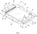
- a cooler 1 includes a cooling plate 10, a first refrigerant introduction member 20, and a second refrigerant introduction member 30.
- the cooling plate 10 is arranged in a bottom portion of a battery 2 to be used as a power supply for a motor configured to drive a vehicle.
- the first refrigerant introduction member 20 is joined to a first cutout portion 11 formed at one end of the cooling plate 10 in a longitudinal direction.
- the second refrigerant introduction member 30 is joined to a second cutout portion 12 formed at another end of the cooling plate 10 in the longitudinal direction.
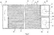
- the cooling plate 10 is formed of a flat extruded profile made of an aluminum alloy, specifically made of an aluminum alloy containing 0.35 mass% to 0.9 mass% of Mg and 0.2 mass% to 0.9 mass% of Si, which includes a plurality of refrigerant flow passages 14 partitioned by a plurality of partition walls 13 parallel to each other along the longitudinal direction, and which has a substantially rectangular shape in plan view.
- a partition wall 13A at the center is formed so as to be thicker than other partition walls 13, and the refrigerant flow passages 14 are divided into a refrigerant inflow side and a refrigerant outflow side with respect to the partition wall 13A at the center.
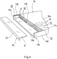
- first cutout portion 11 is formed at one end of the cooling plate 10 in the longitudinal direction.
- the first cutout portion 11 is opened on an upper side and at an end portion in the longitudinal direction while leaving both side walls 10c and 10d in a width direction and one partition wall, that is, the partition wall 13A at the center.
- the first cutout portion 11 has a refrigerant inflow side space 15 and a refrigerant outflow side space 16.
- the refrigerant inflow side space 15 is formed by the partition wall 13A at the center and one side wall 10c.
- the refrigerant outflow side space 16 is formed by the partition wall 13A at the center and another side wall 10d.
- the first refrigerant introduction member 20 joined to the first cutout portion 11 includes a refrigerant inflow side half segment 21 and a refrigerant outflow side half segment 22.
- the refrigerant inflow side half segment 21 is joined to the first cutout portion 11 so as to fill the refrigerant inflow side space 15 of the first cutout portion 11.
- the refrigerant outflow side half segment 22 is joined to the first cutout portion 11 so as to fill the refrigerant outflow side space 16 of the first cutout portion 11.
- the refrigerant inflow side half segment 21 and the refrigerant outflow side half segment 22 are each formed of a plate material made of an aluminum alloy, which includes a horizontal part 23 that fills an upper portion of the refrigerant inflow side space 15 or the refrigerant outflow side space 16 and a vertical part 24 that fills an end portion in the longitudinal direction.
- the horizontal part 23 of the refrigerant inflow side half segment 21 has a refrigerant inflow port 25, and a refrigerant inflow connection pipe 26 made of an aluminum alloy is joined to the refrigerant inflow port 25 through high-frequency brazing described below.
- the horizontal part 23 of the refrigerant outflow side half segment 22 has a refrigerant outflow port 27, and a refrigerant outflow connection pipe 28 made of an aluminum alloy is joined to the refrigerant outflow port 27 through high-frequency brazing described below.
- the refrigerant inflow side half segment 21 and the refrigerant outflow side half segment 22 are each joined to a step portion 17a formed at an opening end of an upper part 10a of the cooling plate 10, side wall step portions 17b formed at upper ends of both the side walls 10c and 10d, partition wall step portions 17c formed at upper ends of the partition wall 13A at the center, and end portions of both the side walls 10c and 10d on the one end side through high-frequency brazing described below.
- the upper part 10a of the cooling plate 10 and the horizontal parts 23 of the refrigerant inflow side half segment 21 and the refrigerant outflow side half segment 22 are in the same plane.
- the second cutout portion 12 is formed at another end of the cooling plate 10 in the longitudinal direction.
- the second cutout portion 12 is opened on an upper side and at an end portion in the longitudinal direction while leaving both the side walls 10c and 10d in the width direction.
- the second refrigerant introduction member 30 joined to the second cutout portion 12 is formed of a plate material made of an aluminum alloy, which includes a horizontal part 31 that fills an upper portion of both the side walls 10c and 10d and a vertical part 32 that fills an end portion in the longitudinal direction.
- the second refrigerant introduction member 30 is joined to a step portion 17a formed at an opening end of the upper part 10a of the cooling plate 10, side wall step portions 17b formed at upper ends of both the side walls 10c and 10d, and end portions of both the side walls 10c and 10d on the other end side through high-frequency brazing described below.
- the upper part 10a of the cooling plate 10 and the horizontal part 31 of the second refrigerant introduction member 30 are in the same plane.
- Flange portions 40 extend along the longitudinal direction at both ends of the cooling plate 10 in the width direction, and a mounting hole 41 in which a fixing screw 50 can be inserted is formed at an appropriate position of each of the flange portions 40.
- the fixing screw 50 to be inserted in the mounting hole 41 is inserted in a mounting hole (not shown) formed in a bracket 3 supporting the battery 2 through intermediation of a spacer 52, and a nut 51 is threadedly engaged with the fixing screw 50.
- the flange portions 40 each have strength in order to securely mount the cooler 1 to the battery 2 and have flatness because mounting accuracy is required.
- the first refrigerant introduction member 20 which has the refrigerant inflow port 25 and the refrigerant outflow port 27 respectively communicating to the refrigerant inflow side and the refrigerant outflow side, is joined to the first cutout portion 11 formed at one end of the cooling plate 10 having a flat shape
- the second refrigerant introduction member 30, which forms the flow passage space 35 causing the refrigerant inflow side and the refrigerant outflow side to communicate to each other is joined to the second cutout portion 12 formed at another end of the cooling plate 10 through brazing. Therefore, as compared to the case in which the refrigerant inflow connection pipe and the refrigerant outflow connection pipe are joined through use of a joint member, the number of components can be decreased, and the space can be reduced.
- the refrigerant inflow side half segment 21 and the refrigerant outflow side half segment 22, which form the first refrigerant introduction member 20, are each joined to the step portion 17a formed at the opening end of the upper part of the cooling plate 10, the side wall step portions 17b formed at the upper ends of both the side walls 10c and 10d, the partition wall step portions 17c formed at the upper ends of the partition wall 13A, and the end portions of both the side walls 10c and 10d on the one end side, and the second refrigerant introduction member 30 is joined to the step portion 17a formed at the opening end of the upper part 10a of the cooling plate 10, the side wall step portions 17b formed at the upper ends of both the side walls 10c and 10d, and the end portions of both the side walls on the other end side.
- joining between the cooling plate 10 and the first refrigerant introduction member 20 (refrigerant inflow side half segment 21 and refrigerant outflow side half segment 22), and joining between the cooling plate 10 and the second refrigerant introduction member 30 can be set easier and stronger.
- the cooling plate 10 is produced by subjecting an aluminum alloy containing 0.35 mass% to 0.9 mass% of Mg and 0.2 mass% to 0.9 mass% of Si to extrusion molding (Step S1).
- the reason why the content of Mg is limited to 0.35 mass% to 0.9 mass% is as described below.
- Mg vaporizes at around 550°C and inhibits a brazing property, and hence when Mg is contained at above 0.9mass%, preferably above 0.6 mass%, the brazing property is reduced.
- a factor for inhibiting the brazing property described above is a factor for reducing the brazing property, such as waste of the flux owing to generation of magnesium fluoride (MgF2) and a reduction in wettability owing to generation of magnesium oxide (MgO) caused by the vaporization of Mg at around 550°C.
- the reason why the content of Si in the cooling plate 10 is limited to from 0.2 mass% to 0.9 mass% is as described below.
- the content of Si is less than 0.2 mass%, a strength increasing effect is not obtained through artificial age hardening treatment described below.
- the content of Si is more than 0.9 mass%, the melting point of the cooling plate 10 (base material) is reduced, and local melting occurs at the time of brazing.
- the cooling plate 10 is subjected to solution treatment (Step S2) and subsequent quenching, followed by being subjected to artificial age hardening treatment (Step S3).
- the artificial age hardening treatment is performed at a temperature of 150°C or more. With this, a strength increasing effect on the cooling plate 10 is obtained through the artificial age hardening treatment.
- the cooling plate 10 having been subjected to the artificial age hardening treatment is processed so that the first cutout portion 11 is formed at the one end in the longitudinal direction, the second cutout portion 12 is formed at the other end, and the refrigerant inflow side space 15, the refrigerant outflow side space 16, the step portions 17a, 17b, and 17c, and the like are formed as described above.
- the first refrigerant introduction member 20, the second refrigerant introduction member 30, the refrigerant supply pipe 26, and the refrigerant discharge pipe 28 prepared in advance are assembled to the cooling plate 10 produced as described above (Step S4).
- a connecting portion of the cooling plate 10 the first refrigerant introduction member 20, the second refrigerant introduction member 30, the refrigerant supply pipe 26, and the refrigerant discharge pipe 28 is subjected to high-frequency brazing with the aluminum alloy brazing filler metal in a powder form containing 27 mass% to 37 mass% of Cu and 5 mass% to 10 mass% of Si, with the balance being Al and inevitable impurities, and the fluoride-based flux containing 11 mass% or more of CsF as a solid content through heating through application of a high-frequency current to a high-frequency heating coil located at the connecting portion of the cooling plate 10, the first and second refrigerant introduction members 20 and 30, the refrigerant supply pipe 26, and the refrigerant discharge pipe 28 (Step S5).
- the reason why the fluoride-based flux containing 11 mass% or more of CsF as a solid content is used is as described below.
- the content of CsF is less than 11 mass%, the melting temperature of the flux is not reduced sufficiently, and hence the brazing cannot be performed at 530°C.
- a frequency (kHz), a current (A), a heating time period (sec), and the like are controlled by a control unit so that the brazing is performed at a temperature of 530°C or more.
- Step 5a When a portion in the vicinity of a brazing portion is required to have strength and flatness at the time of high-frequency brazing, it is desired to perform the brazing while cooling the vicinity portion with a refrigerant for cooling in order to prevent softening of the vicinity portion owing to an increase in temperature through thermal conduction from the brazing portion (a portion to be heated) (Step 5a).
- FIG. 9A An example of a cooling method in this case is described with reference to FIG. 9A and FIG. 9B .
- the cooling means 60 includes: a nozzle block 61 including a refrigerant flow passage 62 causing a refrigerant inflow port 62a and a refrigerant outflow port 62b to communicate to each other; and a refrigerant supply source 64 connected to the refrigerant inflow port 62a of the nozzle block 61 through a refrigerant supply pipe 63 in which a valve V is arranged.
- the nozzle block 61 is formed of a material which has heat resistance and does not induce high-frequency, for example, a member made of an ethylene tetrafluoride resin. Accordingly, the nozzle block 61, which is formed of a material which does not induce high-frequency, is in no danger of generating heat in its material itself, and hence can be used in the vicinity of the heating coil.
- the refrigerant for cooling having outflowed from the refrigerant outflow port 62b is caused to flow toward an end portion 40a side of the flange portion 40, to thereby keep the temperature of the end portion 40a of the flange portion 40 at, for example, 200°C or less.
- a pair of upper and lower guard plates 65 for preventing diffusion are arranged on a refrigerant outflow port 62b side of the nozzle block 61 in order to prevent diffusion of the refrigerant for cooling into the brazing portion 70.
- a liquid such as water, an alcohol, or a mixture liquid thereof, or compressed air may be used as the refrigerant for cooling.
- the liquid removes heat as its vaporization heat when vaporizing at 100°C, and hence when the refrigerant for cooling (liquid) is supplied to the extent that the refrigerant for cooling (liquid) is not exhausted owing to vaporization, softening of the bracket 3 owing to high heat can be prevented.
- a temperature may be controlled by the flow rate of air on the refrigerant outflow port 62b side (a side on which air is ejected).
- cooling may be performed at a pressure of 0.1 MPa or more.
- the refrigerant for cooling is the liquid, such as water, an alcohol, or a mixture liquid thereof, or the compressed air is described in the above-mentioned embodiment, but instead of the embodiment, a gel refrigerant for cooling, for example, COOLGEL (trademark: manufactured by LA-CO Industries, Inc.) may be allowed to adhere to the end portion 40a of the flange portion 40 through use of a spray-type nozzle (not shown) to cool the end portion 40a.
- COOLGEL trademark: manufactured by LA-CO Industries, Inc.
- the guard plates 65 for preventing diffusion may have simplified structures as illustrated in FIG. 9B .
- the lower guard plate 65 for preventing diffusion is desirably formed into a dish shape so that the refrigerant for cooling accumulates in a portion to be cooled.
- a difference from the melting temperature (610°C or more) of the cooling plate 10 (base material) is increased, and hence temperature control at the time of brazing is facilitated.
- a time period required for the brazing can be shortened.
- the brazing can be performed at a temperature (530°C) lower than about 550°C at which Mg volatilizes, and hence softening of a material and heat strain caused through heating at the time of brazing are suppressed, and thus the airtightness and flatness of the cooler 1 can be improved.
- the strength and thermal conductivity of the constituent member of the cooler 1 can be increased.
- a particular portion in the vicinity of the brazing portion 70 (a portion to be heated) to be subjected to the high-frequency brazing for example, the end portion of the cooling plate 10 in the longitudinal direction and the end portion 40a of the flange portion 40 can be cooled to be kept at a temperature or less at which the strength is not impaired, and hence temperature control at the time of brazing is further facilitated, with the result that the strength of the cooling plate 10 and the flange portion 40 constituting the cooler 1 can be increased and the flatness of these members can be maintained.
- the cooling may be performed by the external cooling means 60, and hence the above-mentioned particular portion, for example, the end portion of the cooling plate 10 in the longitudinal direction and the end portion 40a of the flange portion 40 can be appropriately cooled without influences on the shapes of these portions.
- Example 2 a test for examining the brazing property, flatness, and strength of each of the cooler 1 produced by the manufacturing method according to the present invention (Example), a conventional cooler produced through furnace brazing (Comparative Example 1), and a conventional cooler produced through torch brazing (Comparative Example 2) is described.
- Test pieces having the same dimensions (extrusion processed articles each made of an aluminum alloy containing 0.35 mass% to 0.9 mass% of Mg and 0.2 mass% to 0.9 mass% of Si and subjected to solution treatment, followed by heat treatment at 150°C or more)
- Example 1 Brazing method Brazing filler metal Flux Brazing property Flatness (Dimensi onal change amount) Strength of battery mounting portion
- Comparative Example 2 Torch Clad material KF-AlF3-based Base material melting 1.5 mm 185 MPa or more * Powder ⁇ Aluminum alloy brazing filler metal in a powder form containing 27 mass% to 37 mass% of Cu and 5 mass% to 10 mass% of Si, with the balance being Al and inevitable impurities CsF-containing ⁇ Fluoride-based flux containing 11 mass% or more of CsF as a solid content
- the brazing property was good in each of Example and Comparative Example 1, but the base material (cooling plate) melted in Comparative Example 2.
- the flatness was 0.2 mm in Example.
- the flatness was 1 mm in Comparative Example 1 and 1.5 mm in Comparative Example 2.
- the strength was 185 MPa or more in each of Example and Comparative Example 2, but was 150 MPa or less in Comparative Example 1.
- the shape, heating position, frequency, current, and the like of the high-frequency heating coil need to be controlled.
- a particular portion in the vicinity of the brazing portion 70 (a portion to be heated) to be subjected to the high-frequency brazing for example, the end portion of the cooling plate 10 in the longitudinal direction and the end portion 40a of the flange portion 40 can be cooled to be kept at a temperature or less at which the strength is not impaired, and hence temperature control at the time of brazing is further facilitated, with the result that the strength of the cooling plate 10 and the flange portion 40 constituting the cooler 1 can be increased and the flatness of these members can be maintained.
- the cooling may be performed by the external cooling means 60, and hence the above-mentioned particular portion, for example, the end portion of the cooling plate 10 in the longitudinal direction and the end portion 40a of the flange portion 40 can be appropriately cooled without influences on the shapes of these portions.
Landscapes
- Engineering & Computer Science (AREA)
- Chemical & Material Sciences (AREA)
- Mechanical Engineering (AREA)
- General Chemical & Material Sciences (AREA)
- Electrochemistry (AREA)
- Chemical Kinetics & Catalysis (AREA)
- Manufacturing & Machinery (AREA)
- Materials Engineering (AREA)
- Organic Chemistry (AREA)
- Metallurgy (AREA)
- Physics & Mathematics (AREA)
- Thermal Sciences (AREA)
- Crystallography & Structural Chemistry (AREA)
- Pure & Applied Mathematics (AREA)
- Mathematical Optimization (AREA)
- Mathematical Analysis (AREA)
- General Physics & Mathematics (AREA)
- Algebra (AREA)
- Cooling Or The Like Of Electrical Apparatus (AREA)
- Cooling Or The Like Of Semiconductors Or Solid State Devices (AREA)
- Secondary Cells (AREA)
Applications Claiming Priority (2)
| Application Number | Priority Date | Filing Date | Title |
|---|---|---|---|
| JP2015209726 | 2015-10-26 | ||
| PCT/JP2016/004519 WO2017073021A1 (ja) | 2015-10-26 | 2016-10-07 | 冷却器の製造方法 |
Publications (3)
| Publication Number | Publication Date |
|---|---|
| EP3369512A1 true EP3369512A1 (de) | 2018-09-05 |
| EP3369512A4 EP3369512A4 (de) | 2019-06-12 |
| EP3369512B1 EP3369512B1 (de) | 2021-06-02 |
Family
ID=58630018
Family Applications (1)
| Application Number | Title | Priority Date | Filing Date |
|---|---|---|---|
| EP16859261.6A Active EP3369512B1 (de) | 2015-10-26 | 2016-10-07 | Verfahren zur herstellung einer kühleinheit |
Country Status (5)
| Country | Link |
|---|---|
| US (1) | US10835976B2 (de) |
| EP (1) | EP3369512B1 (de) |
| JP (2) | JP6631637B2 (de) |
| CN (1) | CN108349035B (de) |
| WO (1) | WO2017073021A1 (de) |
Cited By (1)
| Publication number | Priority date | Publication date | Assignee | Title |
|---|---|---|---|---|
| DE102021133489A1 (de) | 2021-12-16 | 2023-06-22 | Dr. Ing. H.C. F. Porsche Aktiengesellschaft | Verfahren zur Bestimmung der Ebenheit eines flächigen Bauteils, insbesondere einer Kühlplatte einer Traktionsbatterie eines Elektrofahrzeugs |
Families Citing this family (15)
| Publication number | Priority date | Publication date | Assignee | Title |
|---|---|---|---|---|
| EP3553876B1 (de) * | 2018-04-09 | 2020-07-22 | Samsung SDI Co., Ltd. | Kältemittelverteiler |
| DE102020000543A1 (de) | 2020-01-24 | 2021-07-29 | Voltabox Ag | Verfahren zum thermischen und insbesondere stoffschlüssigen Verbinden, vorzugsweise Verschweißen, zweier Bauteile |
| WO2020233829A1 (de) * | 2019-05-17 | 2020-11-26 | Voltabox Ag | VERFAHREN ZUM THERMISCHEN UND INSBESONDERE STOFFSCHLÜSSIGEN VERBINDEN, VORZUGSWEISE VERSCHWEIßEN, ZWEIER BAUTEILE |
| KR102845719B1 (ko) * | 2019-06-10 | 2025-08-12 | 현대자동차주식회사 | 배터리 모듈용 냉각블록 및 그 제조방법 |
| CN111653847B (zh) * | 2020-05-20 | 2025-08-12 | 安徽新富新能源科技股份有限公司 | 用于新能源汽车电池包的冷却管及其生产方法 |
| US12115881B2 (en) | 2021-02-10 | 2024-10-15 | Textron Innovations Inc. | Non-integral battery cold plate |
| US11728540B2 (en) * | 2021-02-10 | 2023-08-15 | Textron Innovations Inc. | Double sided battery mounting apparatus |
| US12136720B2 (en) | 2021-02-10 | 2024-11-05 | Textron Innovations Inc. | Battery structural assembly |
| US12176506B2 (en) | 2021-02-10 | 2024-12-24 | Textron Innovations Inc. | Battery cold plate and chassis with interlocking joints |
| KR102867401B1 (ko) * | 2021-05-07 | 2025-09-30 | 주식회사 엘지에너지솔루션 | 전지팩 및 이를 포함하는 디바이스 |
| KR20220170339A (ko) | 2021-06-22 | 2022-12-29 | 주식회사 엘지에너지솔루션 | 전지 모듈 및 이를 포함하는 전지 팩 |
| JP7685462B2 (ja) * | 2022-04-11 | 2025-05-29 | 三桜工業株式会社 | 冷却器 |
| CN115011848B (zh) * | 2022-05-11 | 2023-03-28 | 北京理工大学 | 一种高纯铝合金导线及其制备方法 |
| KR20250043151A (ko) * | 2023-09-21 | 2025-03-28 | 주식회사 엘지에너지솔루션 | 히트싱크 어셈블리 |
| DE102023130623A1 (de) * | 2023-11-06 | 2025-05-08 | Benteler Automobiltechnik Gmbh | Kühlplatte und Verfahren zur Herstellung einer Kühlplatte |
Family Cites Families (26)
| Publication number | Priority date | Publication date | Assignee | Title |
|---|---|---|---|---|
| US2981520A (en) * | 1959-11-09 | 1961-04-25 | Borg Warner | Plate-type heat-exchangers |
| US3087046A (en) * | 1959-11-16 | 1963-04-23 | Ryan Aeronautical Co | Brazing and heat treating apparatus for honeycomb core panels |
| JP2742535B2 (ja) * | 1989-06-20 | 1998-04-22 | ワールド工業株式会社 | ろう付方法とその装置 |
| US5197539A (en) * | 1991-02-11 | 1993-03-30 | Modine Manufacturing Company | Heat exchanger with reduced core depth |
| JPH05125502A (ja) * | 1991-11-08 | 1993-05-21 | Showa Alum Corp | 曲げ加工用アルミニウム合金材の製造方法 |
| JPH1078295A (ja) * | 1996-09-03 | 1998-03-24 | Nippon Light Metal Co Ltd | 熱交換器 |
| JPH10216930A (ja) | 1997-02-12 | 1998-08-18 | Keiji Matsumoto | 熱交換器におけるチューブと継手管の接合方法 |
| JP3483860B2 (ja) | 2001-03-08 | 2004-01-06 | 株式会社大進工業研究所 | ろう付け方法及びろう付け装置 |
| JP2004198004A (ja) * | 2002-12-17 | 2004-07-15 | Showa Denko Kk | 熱交換器およびその製造方法 |
| US20050061804A1 (en) * | 2003-09-22 | 2005-03-24 | Norman Golm | Induction flux concentrator utilized for forming heat exchangers |
| DE10353577A1 (de) * | 2003-11-14 | 2005-06-16 | Behr Gmbh & Co. Kg | Hochtemperaturgelöteter Abgaswärmetauscher |
| JP4360309B2 (ja) * | 2004-10-19 | 2009-11-11 | 日本軽金属株式会社 | アルミニウム合金ろう付け混合スラリー及びそれを用いたサンドイッチパネル製造方法 |
| JP4635796B2 (ja) * | 2005-09-21 | 2011-02-23 | 日本軽金属株式会社 | アルミニウム合金鋳物のろう付け方法及びろう付けされた液冷部品 |
| FR2933177B1 (fr) * | 2008-06-26 | 2018-05-25 | Valeo Systemes Thermiques Branche Thermique Moteur | Echangeur de chaleur et carter pour l'echangeur |
| JP2010185647A (ja) * | 2009-01-13 | 2010-08-26 | Mitsubishi Alum Co Ltd | フィンチューブ型エアコン熱交換器用アルミニウム合金押出チューブ |
| JP5656706B2 (ja) * | 2011-03-22 | 2015-01-21 | 株式会社豊田自動織機 | 電池温調装置 |
| JP5511778B2 (ja) * | 2011-12-16 | 2014-06-04 | 株式会社デンソー | 熱交換器の製造方法、ならびに、当該製造方法により製造された熱交換器 |
| JP2013254787A (ja) | 2012-06-05 | 2013-12-19 | Sumitomo Light Metal Ind Ltd | 熱交換器及びその製造方法 |
| JP5532462B2 (ja) * | 2013-04-15 | 2014-06-25 | 昭和電工株式会社 | アルミ合金製塑性加工品の製造方法 |
| JP2015065091A (ja) * | 2013-09-25 | 2015-04-09 | 株式会社東芝 | 誘導加熱装置および誘導加熱方法 |
| US10557188B2 (en) * | 2014-03-19 | 2020-02-11 | Rio Tinto Alcan International Limited | Aluminum alloy composition and method |
| WO2015159797A1 (ja) * | 2014-04-14 | 2015-10-22 | シャープ株式会社 | 型、型の製造方法、反射防止膜および反射防止膜の製造方法 |
| JP6513427B2 (ja) * | 2015-02-27 | 2019-05-15 | 昭和電工株式会社 | 液冷式冷却装置 |
| JP6363555B2 (ja) * | 2015-04-28 | 2018-07-25 | 株式会社デンソー | アルミニウム製熱交換器 |
| JP2016222958A (ja) * | 2015-05-28 | 2016-12-28 | 株式会社神戸製鋼所 | 高強度アルミニウム合金板 |
| WO2017022244A1 (ja) * | 2015-08-05 | 2017-02-09 | 日軽熱交株式会社 | 冷却器 |
-
2016
- 2016-10-07 JP JP2017547602A patent/JP6631637B2/ja active Active
- 2016-10-07 CN CN201680062204.5A patent/CN108349035B/zh active Active
- 2016-10-07 US US15/767,185 patent/US10835976B2/en active Active
- 2016-10-07 EP EP16859261.6A patent/EP3369512B1/de active Active
- 2016-10-07 WO PCT/JP2016/004519 patent/WO2017073021A1/ja not_active Ceased
-
2019
- 2019-05-20 JP JP2019094336A patent/JP6828767B2/ja active Active
Cited By (2)
| Publication number | Priority date | Publication date | Assignee | Title |
|---|---|---|---|---|
| DE102021133489A1 (de) | 2021-12-16 | 2023-06-22 | Dr. Ing. H.C. F. Porsche Aktiengesellschaft | Verfahren zur Bestimmung der Ebenheit eines flächigen Bauteils, insbesondere einer Kühlplatte einer Traktionsbatterie eines Elektrofahrzeugs |
| DE102021133489B4 (de) | 2021-12-16 | 2024-02-29 | Dr. Ing. H.C. F. Porsche Aktiengesellschaft | Verfahren zur Bestimmung der Ebenheit eines flächigen Bauteils, insbesondere einer Kühlplatte einer Traktionsbatterie eines Elektrofahrzeugs |
Also Published As
| Publication number | Publication date |
|---|---|
| CN108349035B (zh) | 2020-08-11 |
| JP6828767B2 (ja) | 2021-02-10 |
| EP3369512A4 (de) | 2019-06-12 |
| EP3369512B1 (de) | 2021-06-02 |
| JPWO2017073021A1 (ja) | 2018-07-12 |
| CN108349035A (zh) | 2018-07-31 |
| JP2019193948A (ja) | 2019-11-07 |
| JP6631637B2 (ja) | 2020-01-15 |
| WO2017073021A1 (ja) | 2017-05-04 |
| US10835976B2 (en) | 2020-11-17 |
| US20180304390A1 (en) | 2018-10-25 |
Similar Documents
| Publication | Publication Date | Title |
|---|---|---|
| EP3369512A1 (de) | Verfahren zur herstellung einer kühleinheit | |
| US10648748B2 (en) | Cooler | |
| US20170021740A1 (en) | Underbody of an electrically driven motor vehicle | |
| JP6186146B2 (ja) | 熱交換器 | |
| EP2848354A1 (de) | Lötblech aus aluminiumlegierung | |
| JP7042023B2 (ja) | ろう付方法 | |
| US20170181332A1 (en) | Liquid-cooled electric drive component, powertrain, vehicle and method | |
| KR102286158B1 (ko) | 브레이징 열 교환기 제조 방법 및 장치 | |
| EP3508595B2 (de) | Lötblech aus aluminiumlegierung | |
| EP4432776A1 (de) | Elektrische heizung, wärmeverwaltungssystem, elektrofahrzeug und energiespeichersystem | |
| US20120247741A1 (en) | Heat exchanger and method of joining heat exchanger pipe | |
| US20180331348A1 (en) | Aluminum alloy plate for bus bars, which has excellent laser weldability | |
| JP6092670B2 (ja) | 熱交換器 | |
| JP2017052090A (ja) | 緊締ジョーおよび緊締ジョーを製造する方法 | |
| CN112072219A (zh) | 用于电池模块的冷却块及其制造方法 | |
| JP7424869B2 (ja) | フレームユニットおよびフレーム組立体 | |
| JP6184176B2 (ja) | アルミニウム材のろう付け炉及びろう付け方法 | |
| JP2014013848A (ja) | 熱交換器 | |
| KR20220117420A (ko) | 자동차 배터리 냉각 시스템 | |
| JP2021131996A (ja) | フレーム組立体および車載用バッテリートレイ | |
| US20190084036A1 (en) | Method for producing a cast metal part, in particular a housing of an electric motor stator, a housing for components of power electronics, a battery tray or a battery housing, cast part produced using the method, and use of a cooling channel produced by roll welding | |
| WO2025188960A1 (en) | New aluminum alloy heat exchangers and methods of making the same | |
| WO2023053580A1 (ja) | パワーデバイス用冷却器 | |
| US20230150048A1 (en) | Brazed aluminum member and method for producing brazed product | |
| KR20250171064A (ko) | 주조용 인서트 파이프 |
Legal Events
| Date | Code | Title | Description |
|---|---|---|---|
| STAA | Information on the status of an ep patent application or granted ep patent |
Free format text: STATUS: THE INTERNATIONAL PUBLICATION HAS BEEN MADE |
|
| PUAI | Public reference made under article 153(3) epc to a published international application that has entered the european phase |
Free format text: ORIGINAL CODE: 0009012 |
|
| STAA | Information on the status of an ep patent application or granted ep patent |
Free format text: STATUS: REQUEST FOR EXAMINATION WAS MADE |
|
| 17P | Request for examination filed |
Effective date: 20180507 |
|
| AK | Designated contracting states |
Kind code of ref document: A1 Designated state(s): AL AT BE BG CH CY CZ DE DK EE ES FI FR GB GR HR HU IE IS IT LI LT LU LV MC MK MT NL NO PL PT RO RS SE SI SK SM TR |
|
| AX | Request for extension of the european patent |
Extension state: BA ME |
|
| DAV | Request for validation of the european patent (deleted) | ||
| DAX | Request for extension of the european patent (deleted) | ||
| A4 | Supplementary search report drawn up and despatched |
Effective date: 20190514 |
|
| RIC1 | Information provided on ipc code assigned before grant |
Ipc: C22C 21/02 20060101ALI20190508BHEP Ipc: B23K 1/00 20060101AFI20190508BHEP Ipc: H01M 10/6568 20140101ALI20190508BHEP Ipc: B23K 103/10 20060101ALI20190508BHEP Ipc: H01M 10/653 20140101ALI20190508BHEP Ipc: C22F 1/00 20060101ALI20190508BHEP Ipc: C22C 21/00 20060101ALI20190508BHEP Ipc: B23K 35/28 20060101ALI20190508BHEP Ipc: B23K 35/363 20060101ALI20190508BHEP Ipc: C22C 21/14 20060101ALI20190508BHEP Ipc: H01M 10/613 20140101ALI20190508BHEP Ipc: H01M 10/651 20140101ALI20190508BHEP Ipc: H01M 10/6556 20140101ALI20190508BHEP Ipc: H01M 10/6554 20140101ALI20190508BHEP Ipc: H01M 10/625 20140101ALI20190508BHEP Ipc: B23K 35/02 20060101ALI20190508BHEP Ipc: B23K 101/14 20060101ALI20190508BHEP Ipc: C22C 21/08 20060101ALI20190508BHEP Ipc: B23K 1/002 20060101ALI20190508BHEP Ipc: C22F 1/05 20060101ALI20190508BHEP Ipc: B23K 1/19 20060101ALI20190508BHEP |
|
| STAA | Information on the status of an ep patent application or granted ep patent |
Free format text: STATUS: EXAMINATION IS IN PROGRESS |
|
| 17Q | First examination report despatched |
Effective date: 20200605 |
|
| GRAP | Despatch of communication of intention to grant a patent |
Free format text: ORIGINAL CODE: EPIDOSNIGR1 |
|
| STAA | Information on the status of an ep patent application or granted ep patent |
Free format text: STATUS: GRANT OF PATENT IS INTENDED |
|
| INTG | Intention to grant announced |
Effective date: 20201211 |
|
| RIN1 | Information on inventor provided before grant (corrected) |
Inventor name: KIKUCHI, YUICHI Inventor name: SEKI, KAZUHITO Inventor name: MOGI, AKIHIRO Inventor name: HIRAYAMA, TOMOYUKI Inventor name: AKIMOTO, TATSUNORI Inventor name: OTAKI, TAKAO |
|
| GRAS | Grant fee paid |
Free format text: ORIGINAL CODE: EPIDOSNIGR3 |
|
| GRAA | (expected) grant |
Free format text: ORIGINAL CODE: 0009210 |
|
| STAA | Information on the status of an ep patent application or granted ep patent |
Free format text: STATUS: THE PATENT HAS BEEN GRANTED |
|
| REG | Reference to a national code |
Ref country code: CH Ref legal event code: EP |
|
| AK | Designated contracting states |
Kind code of ref document: B1 Designated state(s): AL AT BE BG CH CY CZ DE DK EE ES FI FR GB GR HR HU IE IS IT LI LT LU LV MC MK MT NL NO PL PT RO RS SE SI SK SM TR |
|
| REG | Reference to a national code |
Ref country code: GB Ref legal event code: FG4D |
|
| REG | Reference to a national code |
Ref country code: AT Ref legal event code: REF Ref document number: 1397974 Country of ref document: AT Kind code of ref document: T Effective date: 20210615 |
|
| REG | Reference to a national code |
Ref country code: IE Ref legal event code: FG4D |
|
| REG | Reference to a national code |
Ref country code: DE Ref legal event code: R096 Ref document number: 602016058956 Country of ref document: DE |
|
| REG | Reference to a national code |
Ref country code: LT Ref legal event code: MG9D |
|
| PG25 | Lapsed in a contracting state [announced via postgrant information from national office to epo] |
Ref country code: FI Free format text: LAPSE BECAUSE OF FAILURE TO SUBMIT A TRANSLATION OF THE DESCRIPTION OR TO PAY THE FEE WITHIN THE PRESCRIBED TIME-LIMIT Effective date: 20210602 Ref country code: LT Free format text: LAPSE BECAUSE OF FAILURE TO SUBMIT A TRANSLATION OF THE DESCRIPTION OR TO PAY THE FEE WITHIN THE PRESCRIBED TIME-LIMIT Effective date: 20210602 Ref country code: HR Free format text: LAPSE BECAUSE OF FAILURE TO SUBMIT A TRANSLATION OF THE DESCRIPTION OR TO PAY THE FEE WITHIN THE PRESCRIBED TIME-LIMIT Effective date: 20210602 Ref country code: BG Free format text: LAPSE BECAUSE OF FAILURE TO SUBMIT A TRANSLATION OF THE DESCRIPTION OR TO PAY THE FEE WITHIN THE PRESCRIBED TIME-LIMIT Effective date: 20210902 |
|
| REG | Reference to a national code |
Ref country code: NL Ref legal event code: MP Effective date: 20210602 |
|
| REG | Reference to a national code |
Ref country code: AT Ref legal event code: MK05 Ref document number: 1397974 Country of ref document: AT Kind code of ref document: T Effective date: 20210602 |
|
| PG25 | Lapsed in a contracting state [announced via postgrant information from national office to epo] |
Ref country code: GR Free format text: LAPSE BECAUSE OF FAILURE TO SUBMIT A TRANSLATION OF THE DESCRIPTION OR TO PAY THE FEE WITHIN THE PRESCRIBED TIME-LIMIT Effective date: 20210903 Ref country code: LV Free format text: LAPSE BECAUSE OF FAILURE TO SUBMIT A TRANSLATION OF THE DESCRIPTION OR TO PAY THE FEE WITHIN THE PRESCRIBED TIME-LIMIT Effective date: 20210602 Ref country code: NO Free format text: LAPSE BECAUSE OF FAILURE TO SUBMIT A TRANSLATION OF THE DESCRIPTION OR TO PAY THE FEE WITHIN THE PRESCRIBED TIME-LIMIT Effective date: 20210902 Ref country code: PL Free format text: LAPSE BECAUSE OF FAILURE TO SUBMIT A TRANSLATION OF THE DESCRIPTION OR TO PAY THE FEE WITHIN THE PRESCRIBED TIME-LIMIT Effective date: 20210602 Ref country code: RS Free format text: LAPSE BECAUSE OF FAILURE TO SUBMIT A TRANSLATION OF THE DESCRIPTION OR TO PAY THE FEE WITHIN THE PRESCRIBED TIME-LIMIT Effective date: 20210602 Ref country code: SE Free format text: LAPSE BECAUSE OF FAILURE TO SUBMIT A TRANSLATION OF THE DESCRIPTION OR TO PAY THE FEE WITHIN THE PRESCRIBED TIME-LIMIT Effective date: 20210602 |
|
| PG25 | Lapsed in a contracting state [announced via postgrant information from national office to epo] |
Ref country code: PT Free format text: LAPSE BECAUSE OF FAILURE TO SUBMIT A TRANSLATION OF THE DESCRIPTION OR TO PAY THE FEE WITHIN THE PRESCRIBED TIME-LIMIT Effective date: 20211004 Ref country code: NL Free format text: LAPSE BECAUSE OF FAILURE TO SUBMIT A TRANSLATION OF THE DESCRIPTION OR TO PAY THE FEE WITHIN THE PRESCRIBED TIME-LIMIT Effective date: 20210602 Ref country code: RO Free format text: LAPSE BECAUSE OF FAILURE TO SUBMIT A TRANSLATION OF THE DESCRIPTION OR TO PAY THE FEE WITHIN THE PRESCRIBED TIME-LIMIT Effective date: 20210602 Ref country code: ES Free format text: LAPSE BECAUSE OF FAILURE TO SUBMIT A TRANSLATION OF THE DESCRIPTION OR TO PAY THE FEE WITHIN THE PRESCRIBED TIME-LIMIT Effective date: 20210602 Ref country code: AT Free format text: LAPSE BECAUSE OF FAILURE TO SUBMIT A TRANSLATION OF THE DESCRIPTION OR TO PAY THE FEE WITHIN THE PRESCRIBED TIME-LIMIT Effective date: 20210602 Ref country code: EE Free format text: LAPSE BECAUSE OF FAILURE TO SUBMIT A TRANSLATION OF THE DESCRIPTION OR TO PAY THE FEE WITHIN THE PRESCRIBED TIME-LIMIT Effective date: 20210602 Ref country code: CZ Free format text: LAPSE BECAUSE OF FAILURE TO SUBMIT A TRANSLATION OF THE DESCRIPTION OR TO PAY THE FEE WITHIN THE PRESCRIBED TIME-LIMIT Effective date: 20210602 Ref country code: SM Free format text: LAPSE BECAUSE OF FAILURE TO SUBMIT A TRANSLATION OF THE DESCRIPTION OR TO PAY THE FEE WITHIN THE PRESCRIBED TIME-LIMIT Effective date: 20210602 Ref country code: SK Free format text: LAPSE BECAUSE OF FAILURE TO SUBMIT A TRANSLATION OF THE DESCRIPTION OR TO PAY THE FEE WITHIN THE PRESCRIBED TIME-LIMIT Effective date: 20210602 |
|
| REG | Reference to a national code |
Ref country code: DE Ref legal event code: R097 Ref document number: 602016058956 Country of ref document: DE |
|
| PLBE | No opposition filed within time limit |
Free format text: ORIGINAL CODE: 0009261 |
|
| STAA | Information on the status of an ep patent application or granted ep patent |
Free format text: STATUS: NO OPPOSITION FILED WITHIN TIME LIMIT |
|
| PG25 | Lapsed in a contracting state [announced via postgrant information from national office to epo] |
Ref country code: DK Free format text: LAPSE BECAUSE OF FAILURE TO SUBMIT A TRANSLATION OF THE DESCRIPTION OR TO PAY THE FEE WITHIN THE PRESCRIBED TIME-LIMIT Effective date: 20210602 |
|
| 26N | No opposition filed |
Effective date: 20220303 |
|
| REG | Reference to a national code |
Ref country code: CH Ref legal event code: PL |
|
| PG25 | Lapsed in a contracting state [announced via postgrant information from national office to epo] |
Ref country code: AL Free format text: LAPSE BECAUSE OF FAILURE TO SUBMIT A TRANSLATION OF THE DESCRIPTION OR TO PAY THE FEE WITHIN THE PRESCRIBED TIME-LIMIT Effective date: 20210602 |
|
| REG | Reference to a national code |
Ref country code: BE Ref legal event code: MM Effective date: 20211031 |
|
| GBPC | Gb: european patent ceased through non-payment of renewal fee |
Effective date: 20211007 |
|
| PG25 | Lapsed in a contracting state [announced via postgrant information from national office to epo] |
Ref country code: MC Free format text: LAPSE BECAUSE OF FAILURE TO SUBMIT A TRANSLATION OF THE DESCRIPTION OR TO PAY THE FEE WITHIN THE PRESCRIBED TIME-LIMIT Effective date: 20210602 |
|
| PG25 | Lapsed in a contracting state [announced via postgrant information from national office to epo] |
Ref country code: LU Free format text: LAPSE BECAUSE OF NON-PAYMENT OF DUE FEES Effective date: 20211007 Ref country code: IT Free format text: LAPSE BECAUSE OF FAILURE TO SUBMIT A TRANSLATION OF THE DESCRIPTION OR TO PAY THE FEE WITHIN THE PRESCRIBED TIME-LIMIT Effective date: 20210602 Ref country code: GB Free format text: LAPSE BECAUSE OF NON-PAYMENT OF DUE FEES Effective date: 20211007 Ref country code: BE Free format text: LAPSE BECAUSE OF NON-PAYMENT OF DUE FEES Effective date: 20211031 |
|
| PG25 | Lapsed in a contracting state [announced via postgrant information from national office to epo] |
Ref country code: LI Free format text: LAPSE BECAUSE OF NON-PAYMENT OF DUE FEES Effective date: 20211031 Ref country code: CH Free format text: LAPSE BECAUSE OF NON-PAYMENT OF DUE FEES Effective date: 20211031 |
|
| PG25 | Lapsed in a contracting state [announced via postgrant information from national office to epo] |
Ref country code: FR Free format text: LAPSE BECAUSE OF NON-PAYMENT OF DUE FEES Effective date: 20211031 |
|
| PG25 | Lapsed in a contracting state [announced via postgrant information from national office to epo] |
Ref country code: IE Free format text: LAPSE BECAUSE OF NON-PAYMENT OF DUE FEES Effective date: 20211007 |
|
| PG25 | Lapsed in a contracting state [announced via postgrant information from national office to epo] |
Ref country code: HU Free format text: LAPSE BECAUSE OF FAILURE TO SUBMIT A TRANSLATION OF THE DESCRIPTION OR TO PAY THE FEE WITHIN THE PRESCRIBED TIME-LIMIT; INVALID AB INITIO Effective date: 20161007 |
|
| P01 | Opt-out of the competence of the unified patent court (upc) registered |
Effective date: 20230519 |
|
| PG25 | Lapsed in a contracting state [announced via postgrant information from national office to epo] |
Ref country code: CY Free format text: LAPSE BECAUSE OF FAILURE TO SUBMIT A TRANSLATION OF THE DESCRIPTION OR TO PAY THE FEE WITHIN THE PRESCRIBED TIME-LIMIT Effective date: 20210602 |
|
| PG25 | Lapsed in a contracting state [announced via postgrant information from national office to epo] |
Ref country code: MK Free format text: LAPSE BECAUSE OF FAILURE TO SUBMIT A TRANSLATION OF THE DESCRIPTION OR TO PAY THE FEE WITHIN THE PRESCRIBED TIME-LIMIT Effective date: 20210602 |
|
| PG25 | Lapsed in a contracting state [announced via postgrant information from national office to epo] |
Ref country code: MT Free format text: LAPSE BECAUSE OF FAILURE TO SUBMIT A TRANSLATION OF THE DESCRIPTION OR TO PAY THE FEE WITHIN THE PRESCRIBED TIME-LIMIT Effective date: 20210602 |
|
| PG25 | Lapsed in a contracting state [announced via postgrant information from national office to epo] |
Ref country code: TR Free format text: LAPSE BECAUSE OF FAILURE TO SUBMIT A TRANSLATION OF THE DESCRIPTION OR TO PAY THE FEE WITHIN THE PRESCRIBED TIME-LIMIT Effective date: 20210602 |
|
| PGFP | Annual fee paid to national office [announced via postgrant information from national office to epo] |
Ref country code: DE Payment date: 20251021 Year of fee payment: 10 |