EP3369570A1 - Dispositif de fabrication additive d'objets tridimensionnels - Google Patents
Dispositif de fabrication additive d'objets tridimensionnels Download PDFInfo
- Publication number
- EP3369570A1 EP3369570A1 EP17180089.9A EP17180089A EP3369570A1 EP 3369570 A1 EP3369570 A1 EP 3369570A1 EP 17180089 A EP17180089 A EP 17180089A EP 3369570 A1 EP3369570 A1 EP 3369570A1
- Authority
- EP
- European Patent Office
- Prior art keywords
- flow
- fluid flow
- functional component
- fluid
- along
- Prior art date
- Legal status (The legal status is an assumption and is not a legal conclusion. Google has not performed a legal analysis and makes no representation as to the accuracy of the status listed.)
- Granted
Links
Images


Classifications
-
- B—PERFORMING OPERATIONS; TRANSPORTING
- B29—WORKING OF PLASTICS; WORKING OF SUBSTANCES IN A PLASTIC STATE IN GENERAL
- B29C—SHAPING OR JOINING OF PLASTICS; SHAPING OF MATERIAL IN A PLASTIC STATE, NOT OTHERWISE PROVIDED FOR; AFTER-TREATMENT OF THE SHAPED PRODUCTS, e.g. REPAIRING
- B29C64/00—Additive manufacturing, i.e. manufacturing of three-dimensional [3D] objects by additive deposition, additive agglomeration or additive layering, e.g. by 3D printing, stereolithography or selective laser sintering
- B29C64/10—Processes of additive manufacturing
- B29C64/141—Processes of additive manufacturing using only solid materials
- B29C64/153—Processes of additive manufacturing using only solid materials using layers of powder being selectively joined, e.g. by selective laser sintering or melting
-
- B—PERFORMING OPERATIONS; TRANSPORTING
- B22—CASTING; POWDER METALLURGY
- B22F—WORKING METALLIC POWDER; MANUFACTURE OF ARTICLES FROM METALLIC POWDER; MAKING METALLIC POWDER; APPARATUS OR DEVICES SPECIALLY ADAPTED FOR METALLIC POWDER
- B22F10/00—Additive manufacturing of workpieces or articles from metallic powder
- B22F10/20—Direct sintering or melting
- B22F10/28—Powder bed fusion, e.g. selective laser melting [SLM] or electron beam melting [EBM]
-
- B—PERFORMING OPERATIONS; TRANSPORTING
- B22—CASTING; POWDER METALLURGY
- B22F—WORKING METALLIC POWDER; MANUFACTURE OF ARTICLES FROM METALLIC POWDER; MAKING METALLIC POWDER; APPARATUS OR DEVICES SPECIALLY ADAPTED FOR METALLIC POWDER
- B22F10/00—Additive manufacturing of workpieces or articles from metallic powder
- B22F10/30—Process control
- B22F10/32—Process control of the atmosphere, e.g. composition or pressure in a building chamber
-
- B—PERFORMING OPERATIONS; TRANSPORTING
- B22—CASTING; POWDER METALLURGY
- B22F—WORKING METALLIC POWDER; MANUFACTURE OF ARTICLES FROM METALLIC POWDER; MAKING METALLIC POWDER; APPARATUS OR DEVICES SPECIALLY ADAPTED FOR METALLIC POWDER
- B22F10/00—Additive manufacturing of workpieces or articles from metallic powder
- B22F10/70—Recycling
- B22F10/77—Recycling of gas
-
- B—PERFORMING OPERATIONS; TRANSPORTING
- B22—CASTING; POWDER METALLURGY
- B22F—WORKING METALLIC POWDER; MANUFACTURE OF ARTICLES FROM METALLIC POWDER; MAKING METALLIC POWDER; APPARATUS OR DEVICES SPECIALLY ADAPTED FOR METALLIC POWDER
- B22F12/00—Apparatus or devices specially adapted for additive manufacturing; Auxiliary means for additive manufacturing; Combinations of additive manufacturing apparatus or devices with other processing apparatus or devices
- B22F12/70—Gas flow means
-
- B—PERFORMING OPERATIONS; TRANSPORTING
- B23—MACHINE TOOLS; METAL-WORKING NOT OTHERWISE PROVIDED FOR
- B23K—SOLDERING OR UNSOLDERING; WELDING; CLADDING OR PLATING BY SOLDERING OR WELDING; CUTTING BY APPLYING HEAT LOCALLY, e.g. FLAME CUTTING; WORKING BY LASER BEAM
- B23K26/00—Working by laser beam, e.g. welding, cutting or boring
- B23K26/12—Working by laser beam, e.g. welding, cutting or boring in a special environment or atmosphere, e.g. in an enclosure
- B23K26/123—Working by laser beam, e.g. welding, cutting or boring in a special environment or atmosphere, e.g. in an enclosure in an atmosphere of particular gases
-
- B—PERFORMING OPERATIONS; TRANSPORTING
- B23—MACHINE TOOLS; METAL-WORKING NOT OTHERWISE PROVIDED FOR
- B23K—SOLDERING OR UNSOLDERING; WELDING; CLADDING OR PLATING BY SOLDERING OR WELDING; CUTTING BY APPLYING HEAT LOCALLY, e.g. FLAME CUTTING; WORKING BY LASER BEAM
- B23K26/00—Working by laser beam, e.g. welding, cutting or boring
- B23K26/14—Working by laser beam, e.g. welding, cutting or boring using a fluid stream, e.g. a jet of gas, in conjunction with the laser beam; Nozzles therefor
- B23K26/142—Working by laser beam, e.g. welding, cutting or boring using a fluid stream, e.g. a jet of gas, in conjunction with the laser beam; Nozzles therefor for the removal of by-products
-
- B—PERFORMING OPERATIONS; TRANSPORTING
- B23—MACHINE TOOLS; METAL-WORKING NOT OTHERWISE PROVIDED FOR
- B23K—SOLDERING OR UNSOLDERING; WELDING; CLADDING OR PLATING BY SOLDERING OR WELDING; CUTTING BY APPLYING HEAT LOCALLY, e.g. FLAME CUTTING; WORKING BY LASER BEAM
- B23K26/00—Working by laser beam, e.g. welding, cutting or boring
- B23K26/14—Working by laser beam, e.g. welding, cutting or boring using a fluid stream, e.g. a jet of gas, in conjunction with the laser beam; Nozzles therefor
- B23K26/1435—Working by laser beam, e.g. welding, cutting or boring using a fluid stream, e.g. a jet of gas, in conjunction with the laser beam; Nozzles therefor involving specially adapted flow-control means
- B23K26/1438—Working by laser beam, e.g. welding, cutting or boring using a fluid stream, e.g. a jet of gas, in conjunction with the laser beam; Nozzles therefor involving specially adapted flow-control means for directional control
-
- B—PERFORMING OPERATIONS; TRANSPORTING
- B23—MACHINE TOOLS; METAL-WORKING NOT OTHERWISE PROVIDED FOR
- B23K—SOLDERING OR UNSOLDERING; WELDING; CLADDING OR PLATING BY SOLDERING OR WELDING; CUTTING BY APPLYING HEAT LOCALLY, e.g. FLAME CUTTING; WORKING BY LASER BEAM
- B23K26/00—Working by laser beam, e.g. welding, cutting or boring
- B23K26/14—Working by laser beam, e.g. welding, cutting or boring using a fluid stream, e.g. a jet of gas, in conjunction with the laser beam; Nozzles therefor
- B23K26/144—Working by laser beam, e.g. welding, cutting or boring using a fluid stream, e.g. a jet of gas, in conjunction with the laser beam; Nozzles therefor the fluid stream containing particles, e.g. powder
-
- B—PERFORMING OPERATIONS; TRANSPORTING
- B23—MACHINE TOOLS; METAL-WORKING NOT OTHERWISE PROVIDED FOR
- B23K—SOLDERING OR UNSOLDERING; WELDING; CLADDING OR PLATING BY SOLDERING OR WELDING; CUTTING BY APPLYING HEAT LOCALLY, e.g. FLAME CUTTING; WORKING BY LASER BEAM
- B23K26/00—Working by laser beam, e.g. welding, cutting or boring
- B23K26/14—Working by laser beam, e.g. welding, cutting or boring using a fluid stream, e.g. a jet of gas, in conjunction with the laser beam; Nozzles therefor
- B23K26/1462—Nozzles; Features related to nozzles
-
- B—PERFORMING OPERATIONS; TRANSPORTING
- B29—WORKING OF PLASTICS; WORKING OF SUBSTANCES IN A PLASTIC STATE IN GENERAL
- B29C—SHAPING OR JOINING OF PLASTICS; SHAPING OF MATERIAL IN A PLASTIC STATE, NOT OTHERWISE PROVIDED FOR; AFTER-TREATMENT OF THE SHAPED PRODUCTS, e.g. REPAIRING
- B29C64/00—Additive manufacturing, i.e. manufacturing of three-dimensional [3D] objects by additive deposition, additive agglomeration or additive layering, e.g. by 3D printing, stereolithography or selective laser sintering
- B29C64/20—Apparatus for additive manufacturing; Details thereof or accessories therefor
- B29C64/264—Arrangements for irradiation
- B29C64/268—Arrangements for irradiation using laser beams; using electron beams [EB]
-
- B—PERFORMING OPERATIONS; TRANSPORTING
- B33—ADDITIVE MANUFACTURING TECHNOLOGY
- B33Y—ADDITIVE MANUFACTURING, i.e. MANUFACTURING OF THREE-DIMENSIONAL [3D] OBJECTS BY ADDITIVE DEPOSITION, ADDITIVE AGGLOMERATION OR ADDITIVE LAYERING, e.g. BY 3D PRINTING, STEREOLITHOGRAPHY OR SELECTIVE LASER SINTERING
- B33Y40/00—Auxiliary operations or equipment, e.g. for material handling
-
- B—PERFORMING OPERATIONS; TRANSPORTING
- B22—CASTING; POWDER METALLURGY
- B22F—WORKING METALLIC POWDER; MANUFACTURE OF ARTICLES FROM METALLIC POWDER; MAKING METALLIC POWDER; APPARATUS OR DEVICES SPECIALLY ADAPTED FOR METALLIC POWDER
- B22F10/00—Additive manufacturing of workpieces or articles from metallic powder
-
- B—PERFORMING OPERATIONS; TRANSPORTING
- B29—WORKING OF PLASTICS; WORKING OF SUBSTANCES IN A PLASTIC STATE IN GENERAL
- B29C—SHAPING OR JOINING OF PLASTICS; SHAPING OF MATERIAL IN A PLASTIC STATE, NOT OTHERWISE PROVIDED FOR; AFTER-TREATMENT OF THE SHAPED PRODUCTS, e.g. REPAIRING
- B29C64/00—Additive manufacturing, i.e. manufacturing of three-dimensional [3D] objects by additive deposition, additive agglomeration or additive layering, e.g. by 3D printing, stereolithography or selective laser sintering
- B29C64/30—Auxiliary operations or equipment
- B29C64/364—Conditioning of environment
- B29C64/371—Conditioning of environment using an environment other than air, e.g. inert gas
-
- B—PERFORMING OPERATIONS; TRANSPORTING
- B33—ADDITIVE MANUFACTURING TECHNOLOGY
- B33Y—ADDITIVE MANUFACTURING, i.e. MANUFACTURING OF THREE-DIMENSIONAL [3D] OBJECTS BY ADDITIVE DEPOSITION, ADDITIVE AGGLOMERATION OR ADDITIVE LAYERING, e.g. BY 3D PRINTING, STEREOLITHOGRAPHY OR SELECTIVE LASER SINTERING
- B33Y10/00—Processes of additive manufacturing
-
- B—PERFORMING OPERATIONS; TRANSPORTING
- B33—ADDITIVE MANUFACTURING TECHNOLOGY
- B33Y—ADDITIVE MANUFACTURING, i.e. MANUFACTURING OF THREE-DIMENSIONAL [3D] OBJECTS BY ADDITIVE DEPOSITION, ADDITIVE AGGLOMERATION OR ADDITIVE LAYERING, e.g. BY 3D PRINTING, STEREOLITHOGRAPHY OR SELECTIVE LASER SINTERING
- B33Y30/00—Apparatus for additive manufacturing; Details thereof or accessories therefor
-
- Y—GENERAL TAGGING OF NEW TECHNOLOGICAL DEVELOPMENTS; GENERAL TAGGING OF CROSS-SECTIONAL TECHNOLOGIES SPANNING OVER SEVERAL SECTIONS OF THE IPC; TECHNICAL SUBJECTS COVERED BY FORMER USPC CROSS-REFERENCE ART COLLECTIONS [XRACs] AND DIGESTS
- Y02—TECHNOLOGIES OR APPLICATIONS FOR MITIGATION OR ADAPTATION AGAINST CLIMATE CHANGE
- Y02P—CLIMATE CHANGE MITIGATION TECHNOLOGIES IN THE PRODUCTION OR PROCESSING OF GOODS
- Y02P10/00—Technologies related to metal processing
- Y02P10/25—Process efficiency
Definitions
- corresponding devices comprise a flow device, which is designed to form a, in particular a circular, along at least one functional component of the devices flowing fluid flow.
- the fluid flow serves, in particular, to remove, in particular particulate, impurities arising from the process - and these are typically so-called smoke or smoke particles - from a process chamber of the devices.
- the fluid flow formed by the flow device is loaded along its flow path with impurities resulting from the process and, in particular after leaving the process chamber, contains corresponding process-caused impurities.
- the fluid flow laden with corresponding impurities typically flows along certain functional components of the devices. Investigations have shown that deposits can form on the functional components as a result of the fluid flow flowing along them, which is loaded with corresponding impurities, which can impair their respective function.
- the flow cross-section of flow-carrying functional components ie, for example, tube-like flow guide elements, can be reduced by appropriate deposits and the flow properties thus impaired.
- the object of the invention is to specify an apparatus for the additive production of three-dimensional objects, in particular with regard to the prevention or reduction of corresponding deposits of functional components.
- the object is achieved by a device for the additive production of three-dimensional objects according to claim 1.
- the dependent claims relate to possible embodiments of the device.
- the device (“device”) described herein is for the additive production of three-dimensional objects, i. H.
- the building material may be a particulate or powdered metal, plastic and / or ceramic material.
- the selective solidification of respective selectively to be consolidated building material layers is based on object-related Bau schemes.
- Corresponding Bauberries describe the geometric-constructive shape of the respective object to be produced additive and can, for example, "geslicte" CAD data of the object to be produced additive.
- the device may be used as an SLM device, i. H.
- SLM selective laser melting
- SLS selective laser sintering method
- SEBS selective electron beam melting
- the device comprises the functional components typically required for carrying out additive construction processes. These include in particular a coating device and an exposure device.
- the coating device is for forming selectively to be exposed or selectively to be solidified building material layers in a construction plane of the device, in which the successive layerwise selective exposure and the consequent successive layerwise selective solidification of building material layers from the means
- a building material which can be hardened by an energy beam is set up, and for this purpose typically comprises a coating element that is movably mounted relative to the building plane, in particular a blade-like or -shaped coating element.
- the exposure device is set up for the selective exposure of building material layers to be selectively solidified in the construction plane of the device and for this purpose typically comprises a radiation generating device which is set up for generating an energy beam and optionally a beam deflection device which is designed to deflect the energy beam selectively to respective exposures Areas of respective building material layers is set up.
- the apparatus further comprises a flow device, which is used to form a first fluid flow flowing at least in sections along at least one functional component of the device, i. H. typically a first gas flow, is set up, which is loaded or loaded with process-related, especially particulate, impurities.
- a flow of the fluid flow along a functional component of the device means that the fluid flow flows at least in sections along an outer and / or inner surface of a respective functional component.
- the flow device typically comprises a flow generating device, i. H. z. B. a fan or suction device.
- the flow generation device is configured to provide a fluid flow having certain flow characteristics, i. H. z. B.
- a corresponding functional component of the device may be a, in particular tubular or -shaped, flow-guiding element.
- a corresponding flow-guiding element can form part of a flow-guiding structure defining a flow path of the fluid flow and through which the fluid flow can flow or flow.
- the fluid flow serves to remove impurities ("impurities") which are produced as a result of the process, in particular particulate matter, and are typically so-called smoke or smoke particles, from a process chamber of the device.
- impurities impurities
- the mentioned flow guide structure is thus typically on the one hand with a flow inlet of the process chamber of the device and on the other hand with a Flow output of the process chamber of the device connected so that the fluid flow flows through the process chamber, wherein it is loaded with corresponding impurities.
- the first fluid flow formed by the flow device is loaded along its flow path with impurities arising from the process and, in particular after leaving the process chamber, contains corresponding impurities arising as a result of the process.
- the flow device is in addition to forming a second fluid flow, i. H. typically a gas flow, set up.
- the flow device is configured to form the second fluid flow in such a way that it flows at least in sections directly along the surface of the at least one functional component of the device between the first fluid flow and the at least one functional component of the device.
- the flow device is thus set up to form a corresponding flow guide of a first and a second fluid flow at least in sections along respective functional components of the device.
- corresponding functional components may additionally be provided, at least in sections, with a surface texture which prevents formation of corresponding deposits.
- a second fluid flow containing no or compared to the first fluid flow (significantly) less impurities caused by the process-related impurities containing first fluid flow and the surface of the respective functional component is the possibility of deposition of corresponding impurities at the respective Function component suppressed or reduced.
- the second fluid flow may be referred to as "guard flow” or “shield flow” as it protects the respective functional component from deposits of contaminants contained in the first fluid flow or shields against deposits of contaminants contained in the first fluid flow.
- the second fluid flow can insofar as a a respective functional component associated "carpet” or “curtain” are considered, which ensures a corresponding protective or shielding effect.
- the mentioned flow guide structure is thus at least partially flowed through by two different fluid flows, wherein the first fluid flow contains corresponding impurities and the second fluid flow contains no or fewer impurities in comparison.
- the second fluid flow flows directly along the surface of a respective functional component, it prevents or reduces the possibility of deposits on the respective functional component.
- the second fluid flow can be fluidly guided in such a way that it blocks the process chamber, ie. H. the place in which corresponding impurities (essentially) arise, does not flow through; Consequently, the second fluid flow can be brought together only after the process chamber with the first fluid flow.
- the second fluid flow may flow through the process chamber at least in sections.
- the second fluid flow may thus optionally flow only along certain sections of the process chamber, in particular those sections of the process chamber in which corresponding deposits typically form (would).
- a corresponding sectionwise flow of the second fluid flow can be realized by a targeted inflow or inflow of the second fluid flow in the region of respective sections of the process chamber.
- the flow device can accordingly be used to form a first and a second fluid flow, which - provided that the second fluid flow flows at least partially directly along the surface of the respective functional component - respectively along one, in particular exposed, outer surface of the at least one functional component of the device and / or flow along an inner surface of the at least one functional component of the device or of a further functional component of the device.
- a respective functional component may have at least one outer surface and optionally at least one inner surface.
- the outer surface of the respective functional component that typically (substantially) defines the outer geometric appearance of the respective functional component comprises at least one outer surface section, along which the first and second fluid flow can flow or flow.
- the inner surface, if any, of the respective functional component includes at least one inner surface portion along which the first and second fluid flows may flow.
- the inner surface of the respective functional component can delimit an inner space through which the first and second fluid flows at least partially through or through.
- the chemical and / or physical properties as well as the fluidic properties of the first and / or second fluid flow may, depending on the chemical and / or physical properties of the possible deposits, d. H. in particular depending on the chemical and / or physical properties of the impurities contained in the first fluid flow, be selected.
- the deposition of contaminants of first chemical and / or physical properties may be prevented by certain first flow characteristics of the second fluid flow while preventing the deposition of impurities of second chemical and / or physical properties by certain second flow characteristics of the second fluid flow.
- a respective functional component may have at least sections, in particular completely, a planar geometric shape, or at least in sections, in particular completely, a cylinder-like or -shaped geometric shape, or at least in sections, in particular completely, a hollow-cylinder-like or -shaped, geometric shape.
- a corresponding functional component of the device can be, for example, a flow guide element, in particular tubular or shaped, also to be designated as a flow tube, whereby the flow interior can be flowed through at least in sections by the first and second fluid flow, or around a flow surface optical element, ie eg an optical Lens, or a protective glass of a protective glass device, via which an energy beam is introduced into the process chamber, an optical device, wherein the flow surface of the first and second fluid flow is flowed over, or about the process chamber of the device limiting process chamber wall, the process chamber wall at least partially from the first and second fluid flow can be overflow act.
- a flow guide element in particular tubular or shaped, also to be designated as a flow tube, whereby the flow interior can be flowed through at least in sections by the first and second fluid flow, or around a flow surface optical element, ie eg an optical Lens, or a protective glass of a protective glass device, via which an energy beam is introduced into the process chamber, an optical
- a functional component of the device can also be a peripheral device that can be assigned or assigned to the device, such as a peripheral device.
- a peripheral device such as a peripheral device.
- each functional component is addressed, on which appropriate deposits can form.
- the first fluid flow and the second fluid flow may differ in at least one flow parameter relating to the flow properties of the respective fluid flow, in particular the flow velocity. Due to the different flow parameters, the possibility of mixing the first and second fluid flow can be reduced. Ideally, the first and the second fluid flow flow parallel with respect to their flow direction and mix as little as possible. In this way, the described protective or shielding effect of the second fluid flow is particularly reliable.
- the first fluid flow may, for example, flow (substantially) linearly, and the second fluid flow may flow around the first fluid flow at least in sections, in particular completely, surrounding it.
- the second fluid flow can flow in a helical or "helical" manner - this may also be understood to mean a second fluid flow flowing in a spiral or in a similar manner; a helically flowing second fluid flow can flow around the first fluid flow so as to surround it helically at least in sections.
- the flow direction of the first and second fluid flows is typically the same in all cases.
- a helical A helical flowing second fluid flow can, for. B. be realized by a suitable, ie in particular an angle inclined, arrangement of nozzle elements.
- the first fluid flow z. B. centrically flow through the functional component, while the second fluid flow at least partially helically, the first fluid flow surrounding between the first Fluid flow and the surface defined by the inner periphery of the functional component flow.
- the first fluid flow and the second fluid flow may also differ in at least one of the physical properties of the respective fluid flow physical parameter, in particular the density. Also by the different physical parameters, the possibility of mixing the first and second fluid flow can be reduced. As mentioned, the first and the second fluid flow ideally flow in parallel with respect to their flow direction and mix as little as possible. In this way, the described protective or shielding effect of the second fluid flow is particularly reliable.
- the second fluid flow z. B. have a higher density than the first fluid flow, which is why the second fluid flow preferably flows directly along the surface of the respective functional component.
- the flow device can be designed to form a fluid flow which flows in a circular manner along at least one functional component of the device.
- respective first and second nozzle elements or respective first and second nozzle element groups on the same or different portions of the flow circuit formed by the circulating fluid flow may be arranged or formed.
- the nozzle elements or nozzle element groups forming the second fluid flow can be arranged at least in sections in the process chamber. It is thus possible for the second fluid flow in the process chamber to be combined with the first fluid flow.
- the nozzle elements or nozzle element groups forming the second fluid flow may alternatively also be arranged before or after the process chamber. It is thus possible for the second fluid flow to be combined with the first fluid flow before or after the process chamber.
- the first and second fluid streams are typically each inert. Consequently, the first and the second fluid flow can each be formed by an inert flow fluid or gas. With a corresponding flow fluid, it may, for. As argon, carbon dioxide or nitrogen act.
- the invention further relates to a method for operating a device for the additive production of three-dimensional objects by successive layer-wise selective exposure and associated successive layer-wise selective solidification of building material layers of a building material hardenable by means of an energy beam, wherein a first fluid flow formed by a flow device, in particular like a loop, along flows at least one functional component of the device, wherein the first fluid flow is loaded with process-related, especially particulate, impurities.
- the method is characterized in that a second fluid flow is additionally formed via the flow device, the second fluid flow between the first fluid flow and the at least one functional component of the device flowing directly along the surface of the at least one functional component of the device. All embodiments in connection with the device apply analogously to this method.
- the invention relates to a method for protecting a functional component, in particular a functional component of a device as described, before, in particular in the region of a surface, adhering, in particular particulate, impurities, wherein a first fluid flow, in particular like a circuit, flows along the functional component, wherein the first fluid flow is loaded with, in particular particulate, impurities.
- the method is characterized in that in addition a second fluid flow is formed, wherein the second fluid flow between the first fluid flow and the at least one functional component flows directly along the surface of the at least one functional component. All versions in connection with the device apply analogously to this method.
- Fig. 1 - shows a schematic diagram of a device 1 according to an embodiment.
- the device 1 is used for the additive production of three-dimensional objects 2, ie in particular technical components or technical component groups, by successive layer-wise selective exposure and associated successive layer-wise selective solidification of building material layers of a solidifiable building material 3, ie, for example, a metal powder, by means of an energy beam 4th , ie in particular a laser beam.
- the selective solidification of respective building material layers to be consolidated takes place on the basis of object-related building data.
- Corresponding Bau stylist describe the geometric or geometrical-constructive shape of each additive to be produced object 2 and may include, for example, "sliced" CAD data of the object to be manufactured 2.
- the device 1 may, for. B. as a laser CUSING® device, ie as a device for carrying out selective laser melting (SLM method) may be formed.
- SLM method selective laser melting
- the device 1 comprises the functional components required for carrying out additive construction processes; in Fig. 1
- a coating device 5 and an exposure device 6 are shown.
- the coating device 5 is for forming selectively to be exposed or selectively to be consolidated building material layers in a building level or a construction field of the device. 1 arranged and for this purpose comprises a relative to a structural plane of the device 1 movably mounted, in particular blade-like or-shaped, coating element (not specified).
- the exposure device 6 is adapted for selectively exposing building material layers to be solidified in the building plane of the device 1 and for this purpose comprises a beam generating device (not shown), which is designed to generate the energy beam 4, optionally a beam deflection device (not shown), which is used to deflect the the beam generating device generated energy beam 4 is set up to be exposed area of a selectively to be solidified building material layer, as well as various optical elements such.
- a beam generating device (not shown), which is designed to generate the energy beam 4
- a beam deflection device (not shown)
- a metering module 7, a building module 8 and an overflow module 9 are shown, which are docked to a lower region of an inertizable process chamber 10 of the device 1.
- the mentioned modules can also form a lower region of the process chamber 10 of the device 1.
- the device 1 further comprises a flow device 11.
- the flow device 11 is designed to form an inert, first fluid flow FS1, d, in particular a circular manner, along at least one functional component of the device 1.
- H. a first inert gas flow, which is loaded or loaded with process-caused, in particular particulate, impurities.
- the first fluid flow FS1 serves to remove, in particular particulate, impurities arising from the process, which are typically so-called smoke or smoke particles, from the process chamber 10 of the device 1.
- the first fluid flow FS1 is thus loaded with process-related impurities along its flow path and, in particular after leaving the process chamber 10, contains corresponding process-caused impurities.
- the flow device 11 comprises a flow generation device 17, ie, for example, a blower or suction device, for forming the first fluid flow FS1.
- the flow generation device 17 is set up to form a fluid flow with specific flow properties, ie, for example, a specific flow velocity and a specific flow profile.
- the flow of the first fluid flow FS1 within the process chamber 10 is illustrated by the arrows shown in solid lines.
- a flow of the first fluid flow FS1 along a functional component of the device 1 is to be understood as meaning that the first fluid flow FS1 flows at least in sections along an outer and / or inner surface of a respective functional component.
- the first fluid flow FS1 then flows through a further tube-like flow guide element 15 via a filter device 16, which is set up to filter corresponding impurities from the first fluid flow FS1. back to the flow device 11.
- Respective flow guide elements 12, 15 form part of a flow guide structure defining a flow path of the first fluid flow FS1.
- Fig. 1 shown embodiment with corresponding functional components in particular to respective flow guide elements 12, 15, process chamber walls 10a, 10b and 10c a protective glass device (not designated) forming protective glass 18, via which an entry of the energy beam 4 in the process chamber 10 takes place.
- the flow device 11 is additionally illustrated to form an arrow represented by the dashed lines , inert second fluid flow FS2, ie, typically a second inert gas, set up.
- the flow device 11 is set up to design the second fluid flow FS2 such that it flows directly between the first fluid flow FS1 and the respective functional component along the surface of the respective functional component.
- the second fluid flow FS2 may be referred to as "protective flow” or “shield flow”, since it protects the respective functional component against deposits of impurities contained in the first fluid flow FS1 or shields against deposits of impurities contained in the first fluid flow FS1.
- the second fluid flow FS2 can be regarded as a "carpet” or “curtain” assigned to a respective functional component, which ensures a corresponding protective or shielding effect.
- the second fluid flow FS2 flows between the first fluid flow FS1 and the flow guide elements 12, 15 limiting Strömungs exchangeselementwandept (see. Fig. 2 . 3 ), between the first fluid flow FS1 and the process chamber 10 bounding process chamber walls 10a, 10b, 10c and in the region of the protective glass device between the first fluid flow FS1 and the protective glass 18 flows.
- the mentioned flow guidance structure is thus traversed by two different fluid flows FS1, FS2, wherein the first fluid flow FS1 (the main portion) contains corresponding impurities and the second fluid flow FS2 contains no or fewer impurities in comparison.
- the flow device 11 may include one, a plurality of nozzle elements 19 Nozzle device (not designated) to be associated.
- the nozzle device is typically arranged or formed in the process chamber-side inflow region 13.
- a first nozzle element 19 or a group of first nozzle elements can be set up to form the first fluid flow FS1, a second nozzle element 19 or a group of second nozzle elements can be configured to form the second fluid flow FS2.
- two parallel flowing fluid flows FS1, FS2 can be selectively generated.
- Corresponding nozzle elements 19 are in Fig. 2 shown.
- the nozzle elements 19 allow a targeted local inflow or inflow of the second fluid flow FS2.
- the first fluid flow FS1 and the second fluid flow FS2 may also differ in at least one physical parameter relating to the physical properties of the respective fluid flow FS1, FS2, in particular the density.
- the possibility of mixing the first and second fluid flow FS1, FS2 can also be reduced by the different physical parameters.
- the first and the second fluid flow FS1, FS2 flow parallel to one another and mix as little as possible.
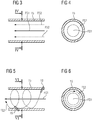
- the Fig. 3, 4 show an enlarged view of in Fig. 1
- the detail A relates to a portion of the flow guiding element 15, which in Fig. 3 in a longitudinally sectioned view and in Fig. 4 is shown in a cross-sectional view.
- the first fluid flow FS1 centric the flow guide element 15 flows.
- the second fluid flow FS2 flows directly between the first fluid flow FS1 and the flow guide element walls delimiting the flow space of the flow guide element 15.
- the first fluid flow FS1 has a disk-shaped flow cross-section
- the second fluid flow FS2 has a ring-shaped flow cross-section surrounding it.
- the flow directions of the first and second fluid flows FS1, FS2 are the same.
- the Fig. 5, 6 show an enlarged view of in Fig. 1 shown detail A in a variant.
- the detail A in turn relates to a portion of the flow guide element 15, which in Fig. 5 in a longitudinally sectioned view and in Fig. 6 is shown in a cross-sectional view.
- the first fluid flow FS1 flows centrally through the flow guide element 15.
- the second fluid flow FS2 flows directly between the first fluid flow FS1 and the flow guide element walls delimiting the flow space of the flow guide element 15.
- the first fluid flow FS1 has a disk-shaped flow cross-section, the second fluid flow FS2 flows around the first fluid flow FS1 in a helical or -shaped manner.
- the formation of a helical flow of the second fluid flow FS2 is z. B. by a suitable, ie in particular one with respect to the central axis of the flow guide element 15 angularly inclined, arrangement of corresponding nozzle elements 19 possible.
- the flow directions of the first and second fluid flows FS1, FS2 are the same.
- a method for operating a device 1 for the additive production of three-dimensional objects 2 by successive layer-wise selective exposure and associated successive layer-wise selective solidification of building material layers can be implemented from a building material 3 that can be hardened by means of an energy beam 4.
- a first fluid flow FS1 formed via the flow device 11 flows along at least one functional component of the device 1, wherein the first fluid flow FS1 is loaded with impurities which are produced by the process, in particular particulate matter.
- a second fluid flow FS2 is formed via the flow device 11, wherein the second fluid flow FS2 between the first fluid flow FS1 and the at least one Function component of the device 1 flows directly along the surface of the at least one functional component of the device 1.
- the method is characterized in that in addition a second fluid flow FS2 is formed, wherein the second fluid flow FS2 flows between the first fluid flow FS1 and the at least one functional component directly along the surface of the at least one functional component.
Landscapes
- Engineering & Computer Science (AREA)
- Chemical & Material Sciences (AREA)
- Materials Engineering (AREA)
- Physics & Mathematics (AREA)
- Optics & Photonics (AREA)
- Manufacturing & Machinery (AREA)
- Mechanical Engineering (AREA)
- Plasma & Fusion (AREA)
- Toxicology (AREA)
- Health & Medical Sciences (AREA)
- Life Sciences & Earth Sciences (AREA)
- Sustainable Development (AREA)
- Automation & Control Theory (AREA)
- Environmental & Geological Engineering (AREA)
- Powder Metallurgy (AREA)
- Producing Shaped Articles From Materials (AREA)
Applications Claiming Priority (1)
| Application Number | Priority Date | Filing Date | Title |
|---|---|---|---|
| DE102017104351.9A DE102017104351A1 (de) | 2017-03-02 | 2017-03-02 | Vorrichtung zur additiven Herstellung dreidimensionaler Objekte |
Publications (2)
| Publication Number | Publication Date |
|---|---|
| EP3369570A1 true EP3369570A1 (fr) | 2018-09-05 |
| EP3369570B1 EP3369570B1 (fr) | 2021-08-25 |
Family
ID=59295104
Family Applications (1)
| Application Number | Title | Priority Date | Filing Date |
|---|---|---|---|
| EP17180089.9A Active EP3369570B1 (fr) | 2017-03-02 | 2017-07-06 | Dispositif de fabrication additive d'objets tridimensionnels |
Country Status (5)
| Country | Link |
|---|---|
| US (1) | US11103953B2 (fr) |
| EP (1) | EP3369570B1 (fr) |
| JP (2) | JP2018145521A (fr) |
| CN (1) | CN108527853A (fr) |
| DE (1) | DE102017104351A1 (fr) |
Families Citing this family (2)
| Publication number | Priority date | Publication date | Assignee | Title |
|---|---|---|---|---|
| US12064921B2 (en) | 2019-10-15 | 2024-08-20 | Hewlett-Packard Development Company, L.P. | Forming a sealed fluid flow path |
| JP2023167406A (ja) * | 2022-05-12 | 2023-11-24 | 三菱重工業株式会社 | 三次元積層装置および方法 |
Citations (6)
| Publication number | Priority date | Publication date | Assignee | Title |
|---|---|---|---|---|
| US5359176A (en) * | 1993-04-02 | 1994-10-25 | International Business Machines Corporation | Optics and environmental protection device for laser processing applications |
| US6583379B1 (en) * | 1998-11-23 | 2003-06-24 | Fraunhofer-Gesellschaft zur Förderung der angewandten Forschung e.V. | Process chamber for selective laser fusion |
| DE102006052292A1 (de) * | 2006-11-03 | 2008-05-08 | Lpkf Laser & Electronics Ag | Vorrichtung und Verfahren zur Bearbeitung eines Werkstücks mittels eines Laserstrahls |
| US20110291331A1 (en) * | 2008-07-18 | 2011-12-01 | Simon Peter Scott | Manufacturing Apparatus and Method |
| US20120251378A1 (en) * | 2009-10-21 | 2012-10-04 | Panasonic Corporation | Process for producing three-dimensionally shaped object and device for producing same |
| WO2016102970A1 (fr) * | 2014-12-23 | 2016-06-30 | Renishaw Plc | Appareil et procédés de fabrication additive |
Family Cites Families (21)
| Publication number | Priority date | Publication date | Assignee | Title |
|---|---|---|---|---|
| US4537629A (en) | 1984-08-20 | 1985-08-27 | Instituto Mexicano De Investigaciones Siderurgicas | Method for obtaining high purity ductile iron |
| JPS63157809A (ja) | 1986-12-19 | 1988-06-30 | Kobe Steel Ltd | 転炉吹錬方法 |
| JPH01222009A (ja) | 1988-02-29 | 1989-09-05 | Nippon Steel Corp | 固体含鉄原料の溶解精錬方法 |
| AU9065991A (en) | 1990-11-09 | 1992-06-11 | Dtm Corporation | Controlled gas flow for selective laser sintering |
| JPH0959708A (ja) | 1995-08-23 | 1997-03-04 | Nippon Steel Corp | ステンレス鋼の効率的な脱炭吹錬方法 |
| JP3764543B2 (ja) | 1996-11-19 | 2006-04-12 | 新日本製鐵株式会社 | 含鉄冷材の溶解方法 |
| JP2001321979A (ja) * | 2000-05-12 | 2001-11-20 | Matsushita Electric Ind Co Ltd | レーザー穴加工機の加工粉集塵装置 |
| JP3479833B2 (ja) * | 2000-08-22 | 2003-12-15 | 日本電気株式会社 | レーザ修正方法および装置 |
| JP4781813B2 (ja) | 2005-12-28 | 2011-09-28 | 新日本製鐵株式会社 | 溶鉄の製造方法 |
| DE102006014694B3 (de) | 2006-03-28 | 2007-10-31 | Eos Gmbh Electro Optical Systems | Prozesskammer und Verfahren für die Bearbeitung eines Werkstoffs mit einem gerichteten Strahl elektromagnetischer Strahlung, insbesondere für eine Lasersintervorrichtung |
| DE102006014835A1 (de) * | 2006-03-30 | 2007-10-04 | Fockele, Matthias, Dr. | Vorrichtung zur Herstellung von Gegenständen durch schichtweises Aufbauen aus pulverförmigem Werkstoff |
| US10808953B2 (en) * | 2013-06-28 | 2020-10-20 | Illinois Tool Works Inc. | Airborne component extractor with baffled debris collection |
| DE102014000022A1 (de) | 2014-01-03 | 2015-07-09 | Cl Schutzrechtsverwaltungs Gmbh | Vorrichtung zum Herstellen von dreidimensionalen Objekten durch aufeinanderfolgendes Verfestigen von Schichten |
| EP3015197B1 (fr) * | 2014-10-30 | 2017-03-08 | MTU Aero Engines GmbH | Dispositif de fabrication ou de réparation d'un objet tridimensionnel |
| EP3147047B1 (fr) * | 2015-09-25 | 2023-08-02 | SLM Solutions Group AG | Appareil de production d'une pièce tridimensionnelle avec un meilleur écoulement de gaz et méthode de production d'une pièce tridimensionnelle |
| CN205130419U (zh) * | 2015-11-28 | 2016-04-06 | 吴江中瑞机电科技有限公司 | 一种用于3d打印机保护窗口的防尘结构 |
| US10071422B2 (en) * | 2015-12-10 | 2018-09-11 | Velo3D, Inc. | Skillful three-dimensional printing |
| EP3321003B1 (fr) | 2016-11-11 | 2019-01-09 | SLM Solutions Group AG | Appareil et méthode de production d'une pièce tridimensionnelle avec écoulement de gaz amélioré |
| DE102016121770A1 (de) | 2016-11-14 | 2018-05-17 | Cl Schutzrechtsverwaltungs Gmbh | Vorrichtung zur additiven Herstellung dreidimensionaler Objekte |
| JP6450784B2 (ja) * | 2017-01-19 | 2019-01-09 | ファナック株式会社 | レーザ加工機 |
| US11383443B2 (en) * | 2017-10-31 | 2022-07-12 | Ihi Corporation | Additive manufacturing device and manufacturing method for additive-manufactured object |
-
2017
- 2017-03-02 DE DE102017104351.9A patent/DE102017104351A1/de active Pending
- 2017-07-06 EP EP17180089.9A patent/EP3369570B1/fr active Active
- 2017-08-24 CN CN201710733415.3A patent/CN108527853A/zh active Pending
-
2018
- 2018-02-02 JP JP2018016853A patent/JP2018145521A/ja active Pending
- 2018-02-22 US US15/902,984 patent/US11103953B2/en active Active
-
2019
- 2019-12-19 JP JP2019229113A patent/JP2020073718A/ja active Pending
Patent Citations (6)
| Publication number | Priority date | Publication date | Assignee | Title |
|---|---|---|---|---|
| US5359176A (en) * | 1993-04-02 | 1994-10-25 | International Business Machines Corporation | Optics and environmental protection device for laser processing applications |
| US6583379B1 (en) * | 1998-11-23 | 2003-06-24 | Fraunhofer-Gesellschaft zur Förderung der angewandten Forschung e.V. | Process chamber for selective laser fusion |
| DE102006052292A1 (de) * | 2006-11-03 | 2008-05-08 | Lpkf Laser & Electronics Ag | Vorrichtung und Verfahren zur Bearbeitung eines Werkstücks mittels eines Laserstrahls |
| US20110291331A1 (en) * | 2008-07-18 | 2011-12-01 | Simon Peter Scott | Manufacturing Apparatus and Method |
| US20120251378A1 (en) * | 2009-10-21 | 2012-10-04 | Panasonic Corporation | Process for producing three-dimensionally shaped object and device for producing same |
| WO2016102970A1 (fr) * | 2014-12-23 | 2016-06-30 | Renishaw Plc | Appareil et procédés de fabrication additive |
Also Published As
| Publication number | Publication date |
|---|---|
| JP2018145521A (ja) | 2018-09-20 |
| US20180250769A1 (en) | 2018-09-06 |
| JP2020073718A (ja) | 2020-05-14 |
| DE102017104351A1 (de) | 2018-09-06 |
| US11103953B2 (en) | 2021-08-31 |
| EP3369570B1 (fr) | 2021-08-25 |
| CN108527853A (zh) | 2018-09-14 |
Similar Documents
| Publication | Publication Date | Title |
|---|---|---|
| EP3321009B1 (fr) | Dispositif de fabrication additive d'objets tridimensionnels | |
| EP3183083B2 (fr) | Procédé de fabrication d'un objet tridimensionnel | |
| DE102014212100A1 (de) | Generatives Herstellungsverfahren und Vorrichtung hierzu mit entgegengesetzt gerichteten Schutzgasströmen | |
| EP3871858A1 (fr) | Dispositif de fabrication générative d'un objet tridimensionnel | |
| EP3321068B1 (fr) | Dispositif de fabrication additive d'objets tridimensionnels | |
| EP3311985A1 (fr) | Dispositif de fabrication additive de composants tridimensionnels | |
| DE102016209933A1 (de) | Vorrichtung und Verfahren zum generativen Herstellen eines dreidimensionalen Objekts | |
| DE112017002704T5 (de) | Additive Fertigungsvorrichtung | |
| EP3620245B1 (fr) | Procédé d'alimentation en courant pour un dispositif de fabrication additive | |
| DE102016005596A1 (de) | Befüllvorrichtung zum befüllen eines medizinischen beutels, verfahren zum herstellen einer derartigen befüllvorrichtung sowie anlage zum herstellen von mit fluiden befüllten medizinischen beuteln | |
| EP3441163A1 (fr) | Dispositif de fabrication additive d'au moins un objet tridimensionnel | |
| EP3372404A1 (fr) | Dispositif de fabrication additive d'objets tridimensionnels | |
| EP3248719B1 (fr) | Procédé et dispositif de fabrication additive d'au moins une partie d'un composant | |
| EP3377236B1 (fr) | Système de production additive d'au moins un objet tridimensionnel | |
| EP3369570B1 (fr) | Dispositif de fabrication additive d'objets tridimensionnels | |
| EP3335858A1 (fr) | Procédé de fabrication additive d'un objet tridimensionnel | |
| DE102021105991A1 (de) | Verfahren zur Herstellung eines dreidimensionalen Bauteils | |
| DE102019209989A1 (de) | Abkühlungsmodul für die Verwendung in einem additiven Fertigungsverfahren | |
| EP3321008B1 (fr) | Dispositif de fabrication additive d'objets tridimensionnels | |
| DE102014207001A1 (de) | Verfahren und Vorrichtung zur Verbesserung der Werkstoffqualität bei generativen Herstellverfahren | |
| DE102018211058A1 (de) | Verfahren zum Filtern eines Gases und Filtervorrichtung für eine Vorrichtung zum schichtweisen Herstellen eines dreidimensionalen Objekts | |
| DE102018212343A1 (de) | Verfahren zum schichtweisen Aufbau eines Bauteils |
Legal Events
| Date | Code | Title | Description |
|---|---|---|---|
| PUAI | Public reference made under article 153(3) epc to a published international application that has entered the european phase |
Free format text: ORIGINAL CODE: 0009012 |
|
| STAA | Information on the status of an ep patent application or granted ep patent |
Free format text: STATUS: THE APPLICATION HAS BEEN PUBLISHED |
|
| AK | Designated contracting states |
Kind code of ref document: A1 Designated state(s): AL AT BE BG CH CY CZ DE DK EE ES FI FR GB GR HR HU IE IS IT LI LT LU LV MC MK MT NL NO PL PT RO RS SE SI SK SM TR |
|
| AX | Request for extension of the european patent |
Extension state: BA ME |
|
| STAA | Information on the status of an ep patent application or granted ep patent |
Free format text: STATUS: REQUEST FOR EXAMINATION WAS MADE |
|
| 17P | Request for examination filed |
Effective date: 20190225 |
|
| RBV | Designated contracting states (corrected) |
Designated state(s): AL AT BE BG CH CY CZ DE DK EE ES FI FR GB GR HR HU IE IS IT LI LT LU LV MC MK MT NL NO PL PT RO RS SE SI SK SM TR |
|
| STAA | Information on the status of an ep patent application or granted ep patent |
Free format text: STATUS: EXAMINATION IS IN PROGRESS |
|
| 17Q | First examination report despatched |
Effective date: 20200414 |
|
| GRAP | Despatch of communication of intention to grant a patent |
Free format text: ORIGINAL CODE: EPIDOSNIGR1 |
|
| STAA | Information on the status of an ep patent application or granted ep patent |
Free format text: STATUS: GRANT OF PATENT IS INTENDED |
|
| INTG | Intention to grant announced |
Effective date: 20210215 |
|
| GRAS | Grant fee paid |
Free format text: ORIGINAL CODE: EPIDOSNIGR3 |
|
| GRAA | (expected) grant |
Free format text: ORIGINAL CODE: 0009210 |
|
| STAA | Information on the status of an ep patent application or granted ep patent |
Free format text: STATUS: THE PATENT HAS BEEN GRANTED |
|
| AK | Designated contracting states |
Kind code of ref document: B1 Designated state(s): AL AT BE BG CH CY CZ DE DK EE ES FI FR GB GR HR HU IE IS IT LI LT LU LV MC MK MT NL NO PL PT RO RS SE SI SK SM TR |
|
| REG | Reference to a national code |
Ref country code: CH Ref legal event code: EP |
|
| REG | Reference to a national code |
Ref country code: DE Ref legal event code: R096 Ref document number: 502017011271 Country of ref document: DE |
|
| REG | Reference to a national code |
Ref country code: IE Ref legal event code: FG4D Free format text: LANGUAGE OF EP DOCUMENT: GERMAN Ref country code: AT Ref legal event code: REF Ref document number: 1423381 Country of ref document: AT Kind code of ref document: T Effective date: 20210915 |
|
| REG | Reference to a national code |
Ref country code: LT Ref legal event code: MG9D |
|
| REG | Reference to a national code |
Ref country code: NL Ref legal event code: MP Effective date: 20210825 |
|
| PG25 | Lapsed in a contracting state [announced via postgrant information from national office to epo] |
Ref country code: NO Free format text: LAPSE BECAUSE OF FAILURE TO SUBMIT A TRANSLATION OF THE DESCRIPTION OR TO PAY THE FEE WITHIN THE PRESCRIBED TIME-LIMIT Effective date: 20211125 Ref country code: PT Free format text: LAPSE BECAUSE OF FAILURE TO SUBMIT A TRANSLATION OF THE DESCRIPTION OR TO PAY THE FEE WITHIN THE PRESCRIBED TIME-LIMIT Effective date: 20211227 Ref country code: HR Free format text: LAPSE BECAUSE OF FAILURE TO SUBMIT A TRANSLATION OF THE DESCRIPTION OR TO PAY THE FEE WITHIN THE PRESCRIBED TIME-LIMIT Effective date: 20210825 Ref country code: ES Free format text: LAPSE BECAUSE OF FAILURE TO SUBMIT A TRANSLATION OF THE DESCRIPTION OR TO PAY THE FEE WITHIN THE PRESCRIBED TIME-LIMIT Effective date: 20210825 Ref country code: FI Free format text: LAPSE BECAUSE OF FAILURE TO SUBMIT A TRANSLATION OF THE DESCRIPTION OR TO PAY THE FEE WITHIN THE PRESCRIBED TIME-LIMIT Effective date: 20210825 Ref country code: LT Free format text: LAPSE BECAUSE OF FAILURE TO SUBMIT A TRANSLATION OF THE DESCRIPTION OR TO PAY THE FEE WITHIN THE PRESCRIBED TIME-LIMIT Effective date: 20210825 Ref country code: BG Free format text: LAPSE BECAUSE OF FAILURE TO SUBMIT A TRANSLATION OF THE DESCRIPTION OR TO PAY THE FEE WITHIN THE PRESCRIBED TIME-LIMIT Effective date: 20211125 Ref country code: SE Free format text: LAPSE BECAUSE OF FAILURE TO SUBMIT A TRANSLATION OF THE DESCRIPTION OR TO PAY THE FEE WITHIN THE PRESCRIBED TIME-LIMIT Effective date: 20210825 Ref country code: RS Free format text: LAPSE BECAUSE OF FAILURE TO SUBMIT A TRANSLATION OF THE DESCRIPTION OR TO PAY THE FEE WITHIN THE PRESCRIBED TIME-LIMIT Effective date: 20210825 |
|
| PG25 | Lapsed in a contracting state [announced via postgrant information from national office to epo] |
Ref country code: PL Free format text: LAPSE BECAUSE OF FAILURE TO SUBMIT A TRANSLATION OF THE DESCRIPTION OR TO PAY THE FEE WITHIN THE PRESCRIBED TIME-LIMIT Effective date: 20210825 Ref country code: LV Free format text: LAPSE BECAUSE OF FAILURE TO SUBMIT A TRANSLATION OF THE DESCRIPTION OR TO PAY THE FEE WITHIN THE PRESCRIBED TIME-LIMIT Effective date: 20210825 Ref country code: GR Free format text: LAPSE BECAUSE OF FAILURE TO SUBMIT A TRANSLATION OF THE DESCRIPTION OR TO PAY THE FEE WITHIN THE PRESCRIBED TIME-LIMIT Effective date: 20211126 |
|
| PG25 | Lapsed in a contracting state [announced via postgrant information from national office to epo] |
Ref country code: NL Free format text: LAPSE BECAUSE OF FAILURE TO SUBMIT A TRANSLATION OF THE DESCRIPTION OR TO PAY THE FEE WITHIN THE PRESCRIBED TIME-LIMIT Effective date: 20210825 |
|
| PG25 | Lapsed in a contracting state [announced via postgrant information from national office to epo] |
Ref country code: DK Free format text: LAPSE BECAUSE OF FAILURE TO SUBMIT A TRANSLATION OF THE DESCRIPTION OR TO PAY THE FEE WITHIN THE PRESCRIBED TIME-LIMIT Effective date: 20210825 |
|
| REG | Reference to a national code |
Ref country code: DE Ref legal event code: R026 Ref document number: 502017011271 Country of ref document: DE |
|
| PLBI | Opposition filed |
Free format text: ORIGINAL CODE: 0009260 |
|
| PLAB | Opposition data, opponent's data or that of the opponent's representative modified |
Free format text: ORIGINAL CODE: 0009299OPPO |
|
| PG25 | Lapsed in a contracting state [announced via postgrant information from national office to epo] |
Ref country code: SM Free format text: LAPSE BECAUSE OF FAILURE TO SUBMIT A TRANSLATION OF THE DESCRIPTION OR TO PAY THE FEE WITHIN THE PRESCRIBED TIME-LIMIT Effective date: 20210825 Ref country code: SK Free format text: LAPSE BECAUSE OF FAILURE TO SUBMIT A TRANSLATION OF THE DESCRIPTION OR TO PAY THE FEE WITHIN THE PRESCRIBED TIME-LIMIT Effective date: 20210825 Ref country code: RO Free format text: LAPSE BECAUSE OF FAILURE TO SUBMIT A TRANSLATION OF THE DESCRIPTION OR TO PAY THE FEE WITHIN THE PRESCRIBED TIME-LIMIT Effective date: 20210825 Ref country code: EE Free format text: LAPSE BECAUSE OF FAILURE TO SUBMIT A TRANSLATION OF THE DESCRIPTION OR TO PAY THE FEE WITHIN THE PRESCRIBED TIME-LIMIT Effective date: 20210825 Ref country code: CZ Free format text: LAPSE BECAUSE OF FAILURE TO SUBMIT A TRANSLATION OF THE DESCRIPTION OR TO PAY THE FEE WITHIN THE PRESCRIBED TIME-LIMIT Effective date: 20210825 Ref country code: AL Free format text: LAPSE BECAUSE OF FAILURE TO SUBMIT A TRANSLATION OF THE DESCRIPTION OR TO PAY THE FEE WITHIN THE PRESCRIBED TIME-LIMIT Effective date: 20210825 |
|
| PLAX | Notice of opposition and request to file observation + time limit sent |
Free format text: ORIGINAL CODE: EPIDOSNOBS2 |
|
| 26 | Opposition filed |
Opponent name: SLM SOLUTIONS GROUP AG Effective date: 20220518 |
|
| R26 | Opposition filed (corrected) |
Opponent name: SLM SOLUTIONS GROUP AG Effective date: 20220518 |
|
| PG25 | Lapsed in a contracting state [announced via postgrant information from national office to epo] |
Ref country code: IT Free format text: LAPSE BECAUSE OF FAILURE TO SUBMIT A TRANSLATION OF THE DESCRIPTION OR TO PAY THE FEE WITHIN THE PRESCRIBED TIME-LIMIT Effective date: 20210825 |
|
| PG25 | Lapsed in a contracting state [announced via postgrant information from national office to epo] |
Ref country code: SI Free format text: LAPSE BECAUSE OF FAILURE TO SUBMIT A TRANSLATION OF THE DESCRIPTION OR TO PAY THE FEE WITHIN THE PRESCRIBED TIME-LIMIT Effective date: 20210825 |
|
| PLBB | Reply of patent proprietor to notice(s) of opposition received |
Free format text: ORIGINAL CODE: EPIDOSNOBS3 |
|
| REG | Reference to a national code |
Ref country code: DE Ref legal event code: R081 Ref document number: 502017011271 Country of ref document: DE Owner name: CONCEPT LASER GMBH, DE Free format text: FORMER OWNER: CL SCHUTZRECHTSVERWALTUNGS GMBH, 96215 LICHTENFELS, DE |
|
| PG25 | Lapsed in a contracting state [announced via postgrant information from national office to epo] |
Ref country code: MC Free format text: LAPSE BECAUSE OF FAILURE TO SUBMIT A TRANSLATION OF THE DESCRIPTION OR TO PAY THE FEE WITHIN THE PRESCRIBED TIME-LIMIT Effective date: 20210825 |
|
| REG | Reference to a national code |
Ref country code: CH Ref legal event code: PL |
|
| REG | Reference to a national code |
Ref country code: BE Ref legal event code: MM Effective date: 20220731 |
|
| PG25 | Lapsed in a contracting state [announced via postgrant information from national office to epo] |
Ref country code: LU Free format text: LAPSE BECAUSE OF NON-PAYMENT OF DUE FEES Effective date: 20220706 Ref country code: LI Free format text: LAPSE BECAUSE OF NON-PAYMENT OF DUE FEES Effective date: 20220731 Ref country code: CH Free format text: LAPSE BECAUSE OF NON-PAYMENT OF DUE FEES Effective date: 20220731 |
|
| RAP2 | Party data changed (patent owner data changed or rights of a patent transferred) |
Owner name: CONCEPT LASER GMBH |
|
| REG | Reference to a national code |
Ref country code: GB Ref legal event code: 732E Free format text: REGISTERED BETWEEN 20230406 AND 20230412 |
|
| PG25 | Lapsed in a contracting state [announced via postgrant information from national office to epo] |
Ref country code: BE Free format text: LAPSE BECAUSE OF NON-PAYMENT OF DUE FEES Effective date: 20220731 |
|
| P01 | Opt-out of the competence of the unified patent court (upc) registered |
Effective date: 20230517 |
|
| PG25 | Lapsed in a contracting state [announced via postgrant information from national office to epo] |
Ref country code: IE Free format text: LAPSE BECAUSE OF NON-PAYMENT OF DUE FEES Effective date: 20220706 |
|
| REG | Reference to a national code |
Ref country code: AT Ref legal event code: MM01 Ref document number: 1423381 Country of ref document: AT Kind code of ref document: T Effective date: 20220706 |
|
| PLAB | Opposition data, opponent's data or that of the opponent's representative modified |
Free format text: ORIGINAL CODE: 0009299OPPO |
|
| PG25 | Lapsed in a contracting state [announced via postgrant information from national office to epo] |
Ref country code: AT Free format text: LAPSE BECAUSE OF NON-PAYMENT OF DUE FEES Effective date: 20220706 |
|
| R26 | Opposition filed (corrected) |
Opponent name: NIKON SLM SOLUTIONS AG Effective date: 20220518 |
|
| PG25 | Lapsed in a contracting state [announced via postgrant information from national office to epo] |
Ref country code: HU Free format text: LAPSE BECAUSE OF FAILURE TO SUBMIT A TRANSLATION OF THE DESCRIPTION OR TO PAY THE FEE WITHIN THE PRESCRIBED TIME-LIMIT; INVALID AB INITIO Effective date: 20170706 |
|
| PG25 | Lapsed in a contracting state [announced via postgrant information from national office to epo] |
Ref country code: MK Free format text: LAPSE BECAUSE OF FAILURE TO SUBMIT A TRANSLATION OF THE DESCRIPTION OR TO PAY THE FEE WITHIN THE PRESCRIBED TIME-LIMIT Effective date: 20210825 Ref country code: CY Free format text: LAPSE BECAUSE OF FAILURE TO SUBMIT A TRANSLATION OF THE DESCRIPTION OR TO PAY THE FEE WITHIN THE PRESCRIBED TIME-LIMIT Effective date: 20210825 |
|
| PG25 | Lapsed in a contracting state [announced via postgrant information from national office to epo] |
Ref country code: TR Free format text: LAPSE BECAUSE OF FAILURE TO SUBMIT A TRANSLATION OF THE DESCRIPTION OR TO PAY THE FEE WITHIN THE PRESCRIBED TIME-LIMIT Effective date: 20210825 |
|
| PG25 | Lapsed in a contracting state [announced via postgrant information from national office to epo] |
Ref country code: MT Free format text: LAPSE BECAUSE OF FAILURE TO SUBMIT A TRANSLATION OF THE DESCRIPTION OR TO PAY THE FEE WITHIN THE PRESCRIBED TIME-LIMIT Effective date: 20210825 |
|
| APBP | Date of receipt of notice of appeal recorded |
Free format text: ORIGINAL CODE: EPIDOSNNOA2O |
|
| APAH | Appeal reference modified |
Free format text: ORIGINAL CODE: EPIDOSCREFNO |
|
| APAW | Appeal reference deleted |
Free format text: ORIGINAL CODE: EPIDOSDREFNO |
|
| APBM | Appeal reference recorded |
Free format text: ORIGINAL CODE: EPIDOSNREFNO |
|
| APBP | Date of receipt of notice of appeal recorded |
Free format text: ORIGINAL CODE: EPIDOSNNOA2O |
|
| APBQ | Date of receipt of statement of grounds of appeal recorded |
Free format text: ORIGINAL CODE: EPIDOSNNOA3O |
|
| APBQ | Date of receipt of statement of grounds of appeal recorded |
Free format text: ORIGINAL CODE: EPIDOSNNOA3O |
|
| PGFP | Annual fee paid to national office [announced via postgrant information from national office to epo] |
Ref country code: GB Payment date: 20250619 Year of fee payment: 9 |
|
| PGFP | Annual fee paid to national office [announced via postgrant information from national office to epo] |
Ref country code: FR Payment date: 20250620 Year of fee payment: 9 |
|
| PGFP | Annual fee paid to national office [announced via postgrant information from national office to epo] |
Ref country code: DE Payment date: 20250620 Year of fee payment: 9 |