EP3369599A1 - Structure de tuyauterie pour véhicule - Google Patents
Structure de tuyauterie pour véhicule Download PDFInfo
- Publication number
- EP3369599A1 EP3369599A1 EP18159734.5A EP18159734A EP3369599A1 EP 3369599 A1 EP3369599 A1 EP 3369599A1 EP 18159734 A EP18159734 A EP 18159734A EP 3369599 A1 EP3369599 A1 EP 3369599A1
- Authority
- EP
- European Patent Office
- Prior art keywords
- vehicle
- pipe
- wheel
- filler neck
- wheel house
- Prior art date
- Legal status (The legal status is an assumption and is not a legal conclusion. Google has not performed a legal analysis and makes no representation as to the accuracy of the status listed.)
- Granted
Links
Images


Classifications
-
- B—PERFORMING OPERATIONS; TRANSPORTING
- B60—VEHICLES IN GENERAL
- B60K—ARRANGEMENT OR MOUNTING OF PROPULSION UNITS OR OF TRANSMISSIONS IN VEHICLES; ARRANGEMENT OR MOUNTING OF PLURAL DIVERSE PRIME-MOVERS IN VEHICLES; AUXILIARY DRIVES FOR VEHICLES; INSTRUMENTATION OR DASHBOARDS FOR VEHICLES; ARRANGEMENTS IN CONNECTION WITH COOLING, AIR INTAKE, GAS EXHAUST OR FUEL SUPPLY OF PROPULSION UNITS IN VEHICLES
- B60K15/00—Arrangement in connection with fuel supply of combustion engines or other fuel consuming energy converters, e.g. fuel cells; Mounting or construction of fuel tanks
- B60K15/01—Arrangement of fuel conduits
-
- B—PERFORMING OPERATIONS; TRANSPORTING
- B60—VEHICLES IN GENERAL
- B60K—ARRANGEMENT OR MOUNTING OF PROPULSION UNITS OR OF TRANSMISSIONS IN VEHICLES; ARRANGEMENT OR MOUNTING OF PLURAL DIVERSE PRIME-MOVERS IN VEHICLES; AUXILIARY DRIVES FOR VEHICLES; INSTRUMENTATION OR DASHBOARDS FOR VEHICLES; ARRANGEMENTS IN CONNECTION WITH COOLING, AIR INTAKE, GAS EXHAUST OR FUEL SUPPLY OF PROPULSION UNITS IN VEHICLES
- B60K13/00—Arrangement in connection with combustion air intake or gas exhaust of propulsion units
- B60K13/04—Arrangement in connection with combustion air intake or gas exhaust of propulsion units concerning exhaust
-
- B—PERFORMING OPERATIONS; TRANSPORTING
- B60—VEHICLES IN GENERAL
- B60K—ARRANGEMENT OR MOUNTING OF PROPULSION UNITS OR OF TRANSMISSIONS IN VEHICLES; ARRANGEMENT OR MOUNTING OF PLURAL DIVERSE PRIME-MOVERS IN VEHICLES; AUXILIARY DRIVES FOR VEHICLES; INSTRUMENTATION OR DASHBOARDS FOR VEHICLES; ARRANGEMENTS IN CONNECTION WITH COOLING, AIR INTAKE, GAS EXHAUST OR FUEL SUPPLY OF PROPULSION UNITS IN VEHICLES
- B60K15/00—Arrangement in connection with fuel supply of combustion engines or other fuel consuming energy converters, e.g. fuel cells; Mounting or construction of fuel tanks
- B60K15/03—Fuel tanks
- B60K15/04—Tank inlets
-
- B—PERFORMING OPERATIONS; TRANSPORTING
- B60—VEHICLES IN GENERAL
- B60K—ARRANGEMENT OR MOUNTING OF PROPULSION UNITS OR OF TRANSMISSIONS IN VEHICLES; ARRANGEMENT OR MOUNTING OF PLURAL DIVERSE PRIME-MOVERS IN VEHICLES; AUXILIARY DRIVES FOR VEHICLES; INSTRUMENTATION OR DASHBOARDS FOR VEHICLES; ARRANGEMENTS IN CONNECTION WITH COOLING, AIR INTAKE, GAS EXHAUST OR FUEL SUPPLY OF PROPULSION UNITS IN VEHICLES
- B60K15/00—Arrangement in connection with fuel supply of combustion engines or other fuel consuming energy converters, e.g. fuel cells; Mounting or construction of fuel tanks
- B60K15/03—Fuel tanks
- B60K15/04—Tank inlets
- B60K15/05—Inlet covers
-
- B—PERFORMING OPERATIONS; TRANSPORTING
- B60—VEHICLES IN GENERAL
- B60K—ARRANGEMENT OR MOUNTING OF PROPULSION UNITS OR OF TRANSMISSIONS IN VEHICLES; ARRANGEMENT OR MOUNTING OF PLURAL DIVERSE PRIME-MOVERS IN VEHICLES; AUXILIARY DRIVES FOR VEHICLES; INSTRUMENTATION OR DASHBOARDS FOR VEHICLES; ARRANGEMENTS IN CONNECTION WITH COOLING, AIR INTAKE, GAS EXHAUST OR FUEL SUPPLY OF PROPULSION UNITS IN VEHICLES
- B60K15/00—Arrangement in connection with fuel supply of combustion engines or other fuel consuming energy converters, e.g. fuel cells; Mounting or construction of fuel tanks
- B60K15/03—Fuel tanks
- B60K2015/03328—Arrangements or special measures related to fuel tanks or fuel handling
- B60K2015/03453—Arrangements or special measures related to fuel tanks or fuel handling for fixing or mounting parts of the fuel tank together
-
- B—PERFORMING OPERATIONS; TRANSPORTING
- B60—VEHICLES IN GENERAL
- B60K—ARRANGEMENT OR MOUNTING OF PROPULSION UNITS OR OF TRANSMISSIONS IN VEHICLES; ARRANGEMENT OR MOUNTING OF PLURAL DIVERSE PRIME-MOVERS IN VEHICLES; AUXILIARY DRIVES FOR VEHICLES; INSTRUMENTATION OR DASHBOARDS FOR VEHICLES; ARRANGEMENTS IN CONNECTION WITH COOLING, AIR INTAKE, GAS EXHAUST OR FUEL SUPPLY OF PROPULSION UNITS IN VEHICLES
- B60K15/00—Arrangement in connection with fuel supply of combustion engines or other fuel consuming energy converters, e.g. fuel cells; Mounting or construction of fuel tanks
- B60K15/03—Fuel tanks
- B60K15/04—Tank inlets
- B60K2015/0458—Details of the tank inlet
- B60K2015/0474—Arrangement of fuel filler pipes in relation to vehicle body
Definitions
- the present invention relates to a piping structure for a vehicle in which a first replenishment opening and a second replenishment opening are provided on a side portion of the vehicle.
- a vehicle that is mounted with a tank of an additive agent having a reduction action on an object to be purified.
- the object to be purified is a nitrogen oxide (NOx)
- an additive agent such as a urea aqueous solution or an ammonia aqueous solution is stored inside the tank.
- the disposition position of the tank for example, it is proposed to set it below the floor of the vehicle (see JP-B-4826612 ).
- a water feed opening for an additive agent is disposed on the floor surface in the vehicle cabin, and the replenishment of the additive agent is carried out in the vehicle cabin.
- the replenishment of the additive agent is carried out in the vehicle cabin.
- baggage is loaded in the vehicle cabin, so that there are cases where excellent workability is not obtained.
- a structure is desired in which the replenishment of the additive agent can be performed from outside the vehicle cabin. For example, it is considered to dispose the water feed opening in the neighborhood of the oil filler opening of the vehicle and connect the water feed opening and the tank by a water feed pipe.
- the vehicle interior space is narrowed by the amount of the space occupied by the water feed pipe, so that the space utilization efficiency can decrease.
- the tank of the additive agent is disposed below the floor of the vehicle, so that it is difficult to improve the space utilization efficiency.
- repair is difficult when the water feed pipe is broken between the outer panel and the inner panel, so that excellent maintainability is not obtained.
- An object of the present application is to provide a piping structure for a vehicle invented in accordance with the above-described problem and intended to improve the space utilization efficiency and the maintainability.
- a piping structure as an embodiment will be described.
- the embodiment shown below is merely an example, and it is not intended to exclude various modifications and technology applications that are not clearly shown in the embodiment shown below.
- the structures of the present embodiment may be modified variously when carried out without departing from the gist thereof. Moreover, they may be chosen as required or may be combined as appropriate.
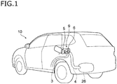
- the piping structure of the present embodiment is applied to a vehicle 10 shown in FIG. 1 .
- This vehicle 10 is an engine vehicle or a hybrid vehicle, and is mounted with a urea SCR (selective catalytic reduction) system that reduces the exhaust components of the engine to purify them.
- An engine of the vehicle 10 is a diesel engine.
- a tank 26 (second tank) storing an additive agent (for example, a urea aqueous solution or an ammonia aqueous solution) for reducing a nitride oxide into nitrogen and a fuel tank 27 (first tank) are disposed.
- an additive agent for example, a urea aqueous solution or an ammonia aqueous solution
- the tank 26 of the present embodiment is provided below the floor and is arranged at a rear of a wheel 19 (rear wheel) in the vehicle 10, and the fuel tank 27 is provided below a part of the floor positioned at a front of the rear wheel 19 and is arranged at a front of the tank 26.
- an outer panel 11 in the vehicle 10 is omitted for easily explaining the internal structure of the wheel house of the vehicle 10.
- a box-shaped filler box 9 having an openable and closable lid (lid member) is provided on a side portion (left rear fender in FIG. 1 ) of the vehicle 10.
- the filler box 9 is arranged at upper of a wheel house 15 which surrounds and contains the rear wheel 19.
- the filler box 9 is fixed to the vehicle body in a position where the open surface to which the lid is attached faces the left side surface of the vehicle 10.
- the shape of the outer surface of the lid is a shape flush with (or a curved surface smoothly connected to) the outer surface of the left rear fender.
- a first replenishment opening 5 and a second replenishment opening 6 are disposed adjacent to each other.
- the first replenishment opening 5 is communicated with the fuel tank 27 and is an oil filler opening for replenishing fuel to the fuel tank 27.
- the second replenishment opening 6 is communicated with the tank 26 and is a water feed opening for replenishing an additive agent to the tank 26.
- a first cap 24 oil filler cap
- a second cap 25 water feed cap
- the first replenishment opening 5 and the fuel tank 27 are connected in a state of communicating with each other through a first filler neck 1 (fuel filler neck) and a first pipe 3 (fuel pipe).
- the first filler neck 1 is a part connected to the first replenishment opening 5, and is formed in a cylindrical shape slightly larger in diameter than the first pipe 3.
- the first pipe 3 is routed on the front side of the wheel 19 in the front-rear direction of the vehicle 10 in a space S formed between the wheel house 15 and a splash shield 18 described later.
- the first pipe 3 of the present embodiment is, as shown in FIG. 2 , routed so as to arc along the outer periphery of the wheel 19 on the front side of the first replenishment opening 5 in a side view. Moreover, the first pipe 3 is connected to the fuel tank 27 disposed below a floor panel 14 on a route passing below a side member 13 in front of the wheel 19.
- the side member 13 is a member disposed below the wheel house 15 and extended in the front-rear direction of the vehicle 10.
- the wheel house 15 is configured as a part of the vehicle 10, is arranged inside the outer panel 11 of the vehicle 10, and is formed in an arch shape covering the upper surface of the wheel 19.
- the wheel house 15 of the present embodiment is, as shown in FIG. 3 , formed of a wheel house inner part 16 and a wheel house outer part 17.
- the wheel house inner part 16 is a member which is disposed inside the vehicle 10 in the vehicle width direction and is made of a steel plate with high-intensity.
- the wheel house outer part 17 is a member which is disposed outside the wheel house inner part 16 in the vehicle width direction and is made of a steel plate with high-intensity. When a structure in which the wheel house inner part 16 is directly fixed to the outer panel 11 is adopted, the wheel house outer part 17 may be omitted.
- the splash shield 18 On the wheel 19 side of the wheel house inner part 16 and the wheel house outer part 17 (inside the wheel house 15), the splash shield 18 for protecting the vehicle body from pebbles and muddy water splashed by the wheel 19 is attached.
- the splash shield 18 is a high-rigidity and high-strength resin-molded article of a shape following the inner shape of the wheel house 15, and is fixed to the wheel house 15 by bolts and nuts, screws, clips or the like.
- the space S is formed between an inner surface of the wheel house 15 and an upper surface of the splash shield 18.
- the second replenishment opening 6 and the tank 26 are connected in a state of communicating with each other through a second filler neck 2 (additive agent filler neck) and a second pipe 4 (additive agent pipe).
- the second filler neck 2 is a part connected to the second replenishment opening 6, and is formed in a shape where the second pipe 4 is connectable to the bottom.
- a flat fixing portion 23 is formed integrally.
- the second pipe 4 is routed on the rear side of the wheel 19 in the space S between the wheel house 15 and the splash shield 18.
- the second pipe 4 of the present embodiment is routed, as shown in FIG. 2 , so as to arc along the outer periphery of the wheel 19 on the rear side of the second replenishment opening 6 in a side view.
- the second pipe 4 is routed between a protector 30 fixed to the side member 13 and the side member 13 in a rear direction of the vehicle so as not to contact both of the protector 30 and the side member 13 behind the wheel 19.
- the protector 30 is a cover attached so as to cover the bent portion of the second pipe 4 (the portion of the second pipe 4 passing below the side member 13).
- the first pipe 3 is fixed to the wheel house inner part 16 through a front bracket 7 in front of the wheel 19. As shown in FIG. 2 , the fixed position of the front bracket 7 is set to a position slightly above the side member 13.
- the first filler neck 1 and the second filler neck 2 are disposed so that the pipe axes thereof are substantially parallel to each other. Moreover, as shown in FIG. 4 , between the first filler neck 1 and the second filler neck 2, a neck bracket 20 connecting them is provided.
- the neck bracket 20 couples the first filler neck 1 and the second filler neck 2 above the wheel 19 in the space S between the wheel house 15 and the splash shield 18.
- the neck bracket 20 is provided with a structure where it becomes a closed cross section including the peripheral surface of the first filler neck 1 on a plane vertical to the pipe axis of the first filler neck 1. As shown in FIG. 5 , the neck bracket 20 includes a first member 21 and a second member 22.
- the first member 21 has a shape such that a plate member is bent in a crank form, and one end thereof is fixed to the peripheral surface of the first filler neck 1. The other end thereof is fixed in a state of being superposed on the second member 22.
- the second member 22 has a shape such that a plate member is bent in a crank form, and one end thereof is fixed to the peripheral surface of the first filler neck 1.
- the fixed position of the second member 22 and the first filler neck 1 is set to a position separated from the fixed position of the first member 21 and the first filler neck 1.
- the second member 22 of the present embodiment is fixed to the peripheral surface of the first filler neck 1 in a position where the first filler neck 1 is sandwiched between it and the first member 21.
- the neck bracket 20 may be formed of three members of the first member 21, the second member 22 and the fixing portion 23.
- the above-described closed cross section structure is trapezoidal (or rectangular) on a plane vertical to the pipe axis of the first filler neck 1, so that stress concentration when a load acts can be avoided. Further, since the members (the first member 21 and the second member 22) on the side of the first pipe 3 and the member (the fixing portion 23) on the side of the second pipe 4 are separate members, the assembly of the pipe 3 and the assembly of the pipe 4 can be easily made independent of each other, so that the workability at the time of manufacture of the vehicle can be improved.
- first pipe 3 for fuel replenishment is disposed on the front side of the wheel and the second pipe 4 for additive agent replenishment is disposed on the rear side of the wheel
- these front and rear positions may be reversed.
- a tank (container) connected to the first pipe 3 or the second pipe 4 may be changed arbitrarily. For example, by disposing the pipes connected to a tank for the engine cooling water and a tank for the window washer liquid inside the wheel house and routing the pipes at a front of and behind the wheel, respectively, a structure similar to the above-described embodiment can be formed.
- the kind of additive agent is not limited to the urea water.
- ammonia is sometimes used instead of urea. Therefore, the above-described tank 26 may be used as an additive agent container storing ammonia aqueous solution.
Landscapes
- Engineering & Computer Science (AREA)
- Chemical & Material Sciences (AREA)
- Combustion & Propulsion (AREA)
- Transportation (AREA)
- Mechanical Engineering (AREA)
- Life Sciences & Earth Sciences (AREA)
- Sustainable Development (AREA)
- Sustainable Energy (AREA)
- Cooling, Air Intake And Gas Exhaust, And Fuel Tank Arrangements In Propulsion Units (AREA)
- Body Structure For Vehicles (AREA)
- Valves And Accessory Devices For Braking Systems (AREA)
Applications Claiming Priority (1)
| Application Number | Priority Date | Filing Date | Title |
|---|---|---|---|
| JP2017040414A JP6862932B2 (ja) | 2017-03-03 | 2017-03-03 | 車両の配管構造 |
Publications (2)
| Publication Number | Publication Date |
|---|---|
| EP3369599A1 true EP3369599A1 (fr) | 2018-09-05 |
| EP3369599B1 EP3369599B1 (fr) | 2022-05-11 |
Family
ID=61557200
Family Applications (1)
| Application Number | Title | Priority Date | Filing Date |
|---|---|---|---|
| EP18159734.5A Active EP3369599B1 (fr) | 2017-03-03 | 2018-03-02 | Structure de tuyauterie pour véhicule |
Country Status (3)
| Country | Link |
|---|---|
| EP (1) | EP3369599B1 (fr) |
| JP (1) | JP6862932B2 (fr) |
| BR (1) | BR102018004356B1 (fr) |
Cited By (1)
| Publication number | Priority date | Publication date | Assignee | Title |
|---|---|---|---|---|
| WO2020049241A1 (fr) * | 2018-09-07 | 2020-03-12 | Psa Automobiles Sa | Dispositif de liaison entre tetes de tubulure de reservoirs et vehicule automobile equipe d'un tel dispositif |
Families Citing this family (3)
| Publication number | Priority date | Publication date | Assignee | Title |
|---|---|---|---|---|
| WO2025186936A1 (fr) * | 2024-03-06 | 2025-09-12 | 三菱自動車工業株式会社 | Structure de carrosserie de véhicule |
| JP7852781B1 (ja) | 2025-05-22 | 2026-04-28 | トヨタ自動車株式会社 | 水素エンジン車両 |
| JP7852782B1 (ja) | 2025-05-22 | 2026-04-28 | トヨタ自動車株式会社 | 水素エンジン車両 |
Citations (4)
| Publication number | Priority date | Publication date | Assignee | Title |
|---|---|---|---|---|
| JPS4826612B1 (fr) | 1968-10-09 | 1973-08-13 | ||
| JPH08296630A (ja) * | 1995-04-27 | 1996-11-12 | Toyota Motor Corp | ヒンジ構造 |
| US20140103039A1 (en) * | 2012-10-12 | 2014-04-17 | Nissan North America, Inc. | Reinforcement Structure for a Vehicle Fuel Filler Tube |
| FR3034052A1 (fr) * | 2015-03-27 | 2016-09-30 | Peugeot Citroen Automobiles Sa | Ensemble de reservoirs de fluides consommables pour vehicule automobile |
Family Cites Families (5)
| Publication number | Priority date | Publication date | Assignee | Title |
|---|---|---|---|---|
| US6554031B2 (en) * | 2001-05-17 | 2003-04-29 | Ford Global Technologies, Inc. | Two fluid dispensing apparatus to supply fuel and reductant to a vehicle |
| JP2008273372A (ja) * | 2007-04-27 | 2008-11-13 | Mazda Motor Corp | 車両における還元剤タンク配設構造 |
| US8167009B2 (en) * | 2008-07-18 | 2012-05-01 | Ford Gobal Technologies, Llc | Adjustable refilling assembly |
| JP6066056B2 (ja) * | 2012-12-14 | 2017-01-25 | 三菱自動車エンジニアリング株式会社 | 車両のタンク構造 |
| JP6010770B2 (ja) * | 2013-09-25 | 2016-10-19 | トヨタ自動車株式会社 | 燃料注入口構造 |
-
2017
- 2017-03-03 JP JP2017040414A patent/JP6862932B2/ja active Active
-
2018
- 2018-03-02 EP EP18159734.5A patent/EP3369599B1/fr active Active
- 2018-03-05 BR BR102018004356-0A patent/BR102018004356B1/pt active IP Right Grant
Patent Citations (4)
| Publication number | Priority date | Publication date | Assignee | Title |
|---|---|---|---|---|
| JPS4826612B1 (fr) | 1968-10-09 | 1973-08-13 | ||
| JPH08296630A (ja) * | 1995-04-27 | 1996-11-12 | Toyota Motor Corp | ヒンジ構造 |
| US20140103039A1 (en) * | 2012-10-12 | 2014-04-17 | Nissan North America, Inc. | Reinforcement Structure for a Vehicle Fuel Filler Tube |
| FR3034052A1 (fr) * | 2015-03-27 | 2016-09-30 | Peugeot Citroen Automobiles Sa | Ensemble de reservoirs de fluides consommables pour vehicule automobile |
Cited By (2)
| Publication number | Priority date | Publication date | Assignee | Title |
|---|---|---|---|---|
| WO2020049241A1 (fr) * | 2018-09-07 | 2020-03-12 | Psa Automobiles Sa | Dispositif de liaison entre tetes de tubulure de reservoirs et vehicule automobile equipe d'un tel dispositif |
| FR3085632A1 (fr) * | 2018-09-07 | 2020-03-13 | Psa Automobiles Sa | Dispositif de liaison entre tetes de tubulure de reservoirs et vehicule automobile equipe d’un tel dispositif |
Also Published As
| Publication number | Publication date |
|---|---|
| JP2018144596A (ja) | 2018-09-20 |
| BR102018004356B1 (pt) | 2024-02-27 |
| JP6862932B2 (ja) | 2021-04-21 |
| EP3369599B1 (fr) | 2022-05-11 |
| BR102018004356A2 (pt) | 2019-01-08 |
Similar Documents
| Publication | Publication Date | Title |
|---|---|---|
| EP3369599B1 (fr) | Structure de tuyauterie pour véhicule | |
| US8056671B2 (en) | Exhaust-gas purification device disposition structure of vehicle | |
| US8813888B2 (en) | Vehicle body rear structure | |
| JP4826612B2 (ja) | 車両の排気浄化装置配設構造 | |
| CN104136690B (zh) | 推土机 | |
| JP2008273372A (ja) | 車両における還元剤タンク配設構造 | |
| WO2012114476A1 (fr) | Structure pour le passage d'un câble à haute tension dans un véhicule | |
| JP2011063147A (ja) | 車両の高電圧ケーブルの配索構造 | |
| JP2014208518A (ja) | 車両の部品搭載構造 | |
| JP2008037135A (ja) | 車体後部のバッテリ搭載構造 | |
| EP3173273B1 (fr) | Carrosserie de véhicule | |
| JP2018145841A (ja) | 車体構造 | |
| JP2010052459A (ja) | 車両の下部車体構造 | |
| JP6281556B2 (ja) | 車両の下部車体構造 | |
| JP2018144597A (ja) | 車体構造 | |
| JP2020023258A (ja) | 車両床下構造 | |
| US11725566B2 (en) | Exhaust structure | |
| JP6582917B2 (ja) | タンク配置構造 | |
| JP7852782B1 (ja) | 水素エンジン車両 | |
| JP6880836B2 (ja) | 車体構造 | |
| JP7852781B1 (ja) | 水素エンジン車両 | |
| JP6930201B2 (ja) | サプライポンプ | |
| JP6848536B2 (ja) | 車体構造 | |
| JP6662281B2 (ja) | 車体構造 | |
| JP2005329758A (ja) | 排気系構造 |
Legal Events
| Date | Code | Title | Description |
|---|---|---|---|
| PUAI | Public reference made under article 153(3) epc to a published international application that has entered the european phase |
Free format text: ORIGINAL CODE: 0009012 |
|
| STAA | Information on the status of an ep patent application or granted ep patent |
Free format text: STATUS: REQUEST FOR EXAMINATION WAS MADE |
|
| 17P | Request for examination filed |
Effective date: 20180402 |
|
| AK | Designated contracting states |
Kind code of ref document: A1 Designated state(s): AL AT BE BG CH CY CZ DE DK EE ES FI FR GB GR HR HU IE IS IT LI LT LU LV MC MK MT NL NO PL PT RO RS SE SI SK SM TR |
|
| AX | Request for extension of the european patent |
Extension state: BA ME |
|
| RAP1 | Party data changed (applicant data changed or rights of an application transferred) |
Owner name: MITSUBISHI JIDOSHA KOGYO KABUSHIKI KAISHA Owner name: MITSUBISHI JIDOSHA ENGINEERING KABUSHIKI KAISHA |
|
| RIC1 | Information provided on ipc code assigned before grant |
Ipc: B60K 15/03 20060101ALI20211025BHEP Ipc: B60K 15/05 20060101ALI20211025BHEP Ipc: B60K 15/04 20060101ALI20211025BHEP Ipc: B60K 13/04 20060101ALI20211025BHEP Ipc: B60K 15/01 20060101AFI20211025BHEP |
|
| GRAP | Despatch of communication of intention to grant a patent |
Free format text: ORIGINAL CODE: EPIDOSNIGR1 |
|
| STAA | Information on the status of an ep patent application or granted ep patent |
Free format text: STATUS: GRANT OF PATENT IS INTENDED |
|
| INTG | Intention to grant announced |
Effective date: 20211207 |
|
| GRAS | Grant fee paid |
Free format text: ORIGINAL CODE: EPIDOSNIGR3 |
|
| GRAA | (expected) grant |
Free format text: ORIGINAL CODE: 0009210 |
|
| STAA | Information on the status of an ep patent application or granted ep patent |
Free format text: STATUS: THE PATENT HAS BEEN GRANTED |
|
| AK | Designated contracting states |
Kind code of ref document: B1 Designated state(s): AL AT BE BG CH CY CZ DE DK EE ES FI FR GB GR HR HU IE IS IT LI LT LU LV MC MK MT NL NO PL PT RO RS SE SI SK SM TR |
|
| REG | Reference to a national code |
Ref country code: GB Ref legal event code: FG4D |
|
| REG | Reference to a national code |
Ref country code: CH Ref legal event code: EP |
|
| REG | Reference to a national code |
Ref country code: AT Ref legal event code: REF Ref document number: 1491113 Country of ref document: AT Kind code of ref document: T Effective date: 20220515 |
|
| REG | Reference to a national code |
Ref country code: DE Ref legal event code: R096 Ref document number: 602018035253 Country of ref document: DE |
|
| REG | Reference to a national code |
Ref country code: IE Ref legal event code: FG4D |
|
| REG | Reference to a national code |
Ref country code: LT Ref legal event code: MG9D |
|
| REG | Reference to a national code |
Ref country code: NL Ref legal event code: MP Effective date: 20220511 |
|
| REG | Reference to a national code |
Ref country code: AT Ref legal event code: MK05 Ref document number: 1491113 Country of ref document: AT Kind code of ref document: T Effective date: 20220511 |
|
| PG25 | Lapsed in a contracting state [announced via postgrant information from national office to epo] |
Ref country code: SE Free format text: LAPSE BECAUSE OF FAILURE TO SUBMIT A TRANSLATION OF THE DESCRIPTION OR TO PAY THE FEE WITHIN THE PRESCRIBED TIME-LIMIT Effective date: 20220511 Ref country code: PT Free format text: LAPSE BECAUSE OF FAILURE TO SUBMIT A TRANSLATION OF THE DESCRIPTION OR TO PAY THE FEE WITHIN THE PRESCRIBED TIME-LIMIT Effective date: 20220912 Ref country code: NO Free format text: LAPSE BECAUSE OF FAILURE TO SUBMIT A TRANSLATION OF THE DESCRIPTION OR TO PAY THE FEE WITHIN THE PRESCRIBED TIME-LIMIT Effective date: 20220811 Ref country code: NL Free format text: LAPSE BECAUSE OF FAILURE TO SUBMIT A TRANSLATION OF THE DESCRIPTION OR TO PAY THE FEE WITHIN THE PRESCRIBED TIME-LIMIT Effective date: 20220511 Ref country code: LT Free format text: LAPSE BECAUSE OF FAILURE TO SUBMIT A TRANSLATION OF THE DESCRIPTION OR TO PAY THE FEE WITHIN THE PRESCRIBED TIME-LIMIT Effective date: 20220511 Ref country code: HR Free format text: LAPSE BECAUSE OF FAILURE TO SUBMIT A TRANSLATION OF THE DESCRIPTION OR TO PAY THE FEE WITHIN THE PRESCRIBED TIME-LIMIT Effective date: 20220511 Ref country code: GR Free format text: LAPSE BECAUSE OF FAILURE TO SUBMIT A TRANSLATION OF THE DESCRIPTION OR TO PAY THE FEE WITHIN THE PRESCRIBED TIME-LIMIT Effective date: 20220812 Ref country code: FI Free format text: LAPSE BECAUSE OF FAILURE TO SUBMIT A TRANSLATION OF THE DESCRIPTION OR TO PAY THE FEE WITHIN THE PRESCRIBED TIME-LIMIT Effective date: 20220511 Ref country code: ES Free format text: LAPSE BECAUSE OF FAILURE TO SUBMIT A TRANSLATION OF THE DESCRIPTION OR TO PAY THE FEE WITHIN THE PRESCRIBED TIME-LIMIT Effective date: 20220511 Ref country code: BG Free format text: LAPSE BECAUSE OF FAILURE TO SUBMIT A TRANSLATION OF THE DESCRIPTION OR TO PAY THE FEE WITHIN THE PRESCRIBED TIME-LIMIT Effective date: 20220811 Ref country code: AT Free format text: LAPSE BECAUSE OF FAILURE TO SUBMIT A TRANSLATION OF THE DESCRIPTION OR TO PAY THE FEE WITHIN THE PRESCRIBED TIME-LIMIT Effective date: 20220511 |
|
| PG25 | Lapsed in a contracting state [announced via postgrant information from national office to epo] |
Ref country code: RS Free format text: LAPSE BECAUSE OF FAILURE TO SUBMIT A TRANSLATION OF THE DESCRIPTION OR TO PAY THE FEE WITHIN THE PRESCRIBED TIME-LIMIT Effective date: 20220511 Ref country code: PL Free format text: LAPSE BECAUSE OF FAILURE TO SUBMIT A TRANSLATION OF THE DESCRIPTION OR TO PAY THE FEE WITHIN THE PRESCRIBED TIME-LIMIT Effective date: 20220511 Ref country code: LV Free format text: LAPSE BECAUSE OF FAILURE TO SUBMIT A TRANSLATION OF THE DESCRIPTION OR TO PAY THE FEE WITHIN THE PRESCRIBED TIME-LIMIT Effective date: 20220511 Ref country code: IS Free format text: LAPSE BECAUSE OF FAILURE TO SUBMIT A TRANSLATION OF THE DESCRIPTION OR TO PAY THE FEE WITHIN THE PRESCRIBED TIME-LIMIT Effective date: 20220911 |
|
| PG25 | Lapsed in a contracting state [announced via postgrant information from national office to epo] |
Ref country code: SM Free format text: LAPSE BECAUSE OF FAILURE TO SUBMIT A TRANSLATION OF THE DESCRIPTION OR TO PAY THE FEE WITHIN THE PRESCRIBED TIME-LIMIT Effective date: 20220511 Ref country code: SK Free format text: LAPSE BECAUSE OF FAILURE TO SUBMIT A TRANSLATION OF THE DESCRIPTION OR TO PAY THE FEE WITHIN THE PRESCRIBED TIME-LIMIT Effective date: 20220511 Ref country code: RO Free format text: LAPSE BECAUSE OF FAILURE TO SUBMIT A TRANSLATION OF THE DESCRIPTION OR TO PAY THE FEE WITHIN THE PRESCRIBED TIME-LIMIT Effective date: 20220511 Ref country code: EE Free format text: LAPSE BECAUSE OF FAILURE TO SUBMIT A TRANSLATION OF THE DESCRIPTION OR TO PAY THE FEE WITHIN THE PRESCRIBED TIME-LIMIT Effective date: 20220511 Ref country code: DK Free format text: LAPSE BECAUSE OF FAILURE TO SUBMIT A TRANSLATION OF THE DESCRIPTION OR TO PAY THE FEE WITHIN THE PRESCRIBED TIME-LIMIT Effective date: 20220511 Ref country code: CZ Free format text: LAPSE BECAUSE OF FAILURE TO SUBMIT A TRANSLATION OF THE DESCRIPTION OR TO PAY THE FEE WITHIN THE PRESCRIBED TIME-LIMIT Effective date: 20220511 |
|
| REG | Reference to a national code |
Ref country code: DE Ref legal event code: R097 Ref document number: 602018035253 Country of ref document: DE |
|
| PLBE | No opposition filed within time limit |
Free format text: ORIGINAL CODE: 0009261 |
|
| STAA | Information on the status of an ep patent application or granted ep patent |
Free format text: STATUS: NO OPPOSITION FILED WITHIN TIME LIMIT |
|
| PG25 | Lapsed in a contracting state [announced via postgrant information from national office to epo] |
Ref country code: AL Free format text: LAPSE BECAUSE OF FAILURE TO SUBMIT A TRANSLATION OF THE DESCRIPTION OR TO PAY THE FEE WITHIN THE PRESCRIBED TIME-LIMIT Effective date: 20220511 |
|
| 26N | No opposition filed |
Effective date: 20230214 |
|
| PG25 | Lapsed in a contracting state [announced via postgrant information from national office to epo] |
Ref country code: SI Free format text: LAPSE BECAUSE OF FAILURE TO SUBMIT A TRANSLATION OF THE DESCRIPTION OR TO PAY THE FEE WITHIN THE PRESCRIBED TIME-LIMIT Effective date: 20220511 |
|
| PG25 | Lapsed in a contracting state [announced via postgrant information from national office to epo] |
Ref country code: MC Free format text: LAPSE BECAUSE OF FAILURE TO SUBMIT A TRANSLATION OF THE DESCRIPTION OR TO PAY THE FEE WITHIN THE PRESCRIBED TIME-LIMIT Effective date: 20220511 |
|
| REG | Reference to a national code |
Ref country code: CH Ref legal event code: PL |
|
| GBPC | Gb: european patent ceased through non-payment of renewal fee |
Effective date: 20230302 |
|
| REG | Reference to a national code |
Ref country code: BE Ref legal event code: MM Effective date: 20230331 |
|
| PG25 | Lapsed in a contracting state [announced via postgrant information from national office to epo] |
Ref country code: LU Free format text: LAPSE BECAUSE OF NON-PAYMENT OF DUE FEES Effective date: 20230302 |
|
| REG | Reference to a national code |
Ref country code: IE Ref legal event code: MM4A |
|
| PG25 | Lapsed in a contracting state [announced via postgrant information from national office to epo] |
Ref country code: GB Free format text: LAPSE BECAUSE OF NON-PAYMENT OF DUE FEES Effective date: 20230302 |
|
| PG25 | Lapsed in a contracting state [announced via postgrant information from national office to epo] |
Ref country code: LI Free format text: LAPSE BECAUSE OF NON-PAYMENT OF DUE FEES Effective date: 20230331 Ref country code: IT Free format text: LAPSE BECAUSE OF FAILURE TO SUBMIT A TRANSLATION OF THE DESCRIPTION OR TO PAY THE FEE WITHIN THE PRESCRIBED TIME-LIMIT Effective date: 20220511 Ref country code: IE Free format text: LAPSE BECAUSE OF NON-PAYMENT OF DUE FEES Effective date: 20230302 Ref country code: GB Free format text: LAPSE BECAUSE OF NON-PAYMENT OF DUE FEES Effective date: 20230302 Ref country code: CH Free format text: LAPSE BECAUSE OF NON-PAYMENT OF DUE FEES Effective date: 20230331 |
|
| PG25 | Lapsed in a contracting state [announced via postgrant information from national office to epo] |
Ref country code: BE Free format text: LAPSE BECAUSE OF NON-PAYMENT OF DUE FEES Effective date: 20230331 |
|
| PG25 | Lapsed in a contracting state [announced via postgrant information from national office to epo] |
Ref country code: BG Free format text: LAPSE BECAUSE OF FAILURE TO SUBMIT A TRANSLATION OF THE DESCRIPTION OR TO PAY THE FEE WITHIN THE PRESCRIBED TIME-LIMIT Effective date: 20220511 |
|
| PG25 | Lapsed in a contracting state [announced via postgrant information from national office to epo] |
Ref country code: BG Free format text: LAPSE BECAUSE OF FAILURE TO SUBMIT A TRANSLATION OF THE DESCRIPTION OR TO PAY THE FEE WITHIN THE PRESCRIBED TIME-LIMIT Effective date: 20220511 |
|
| PG25 | Lapsed in a contracting state [announced via postgrant information from national office to epo] |
Ref country code: CY Free format text: LAPSE BECAUSE OF FAILURE TO SUBMIT A TRANSLATION OF THE DESCRIPTION OR TO PAY THE FEE WITHIN THE PRESCRIBED TIME-LIMIT; INVALID AB INITIO Effective date: 20180302 |
|
| PG25 | Lapsed in a contracting state [announced via postgrant information from national office to epo] |
Ref country code: HU Free format text: LAPSE BECAUSE OF FAILURE TO SUBMIT A TRANSLATION OF THE DESCRIPTION OR TO PAY THE FEE WITHIN THE PRESCRIBED TIME-LIMIT; INVALID AB INITIO Effective date: 20180302 |
|
| PG25 | Lapsed in a contracting state [announced via postgrant information from national office to epo] |
Ref country code: TR Free format text: LAPSE BECAUSE OF FAILURE TO SUBMIT A TRANSLATION OF THE DESCRIPTION OR TO PAY THE FEE WITHIN THE PRESCRIBED TIME-LIMIT Effective date: 20220511 |
|
| PGFP | Annual fee paid to national office [announced via postgrant information from national office to epo] |
Ref country code: DE Payment date: 20260128 Year of fee payment: 9 |
|
| PGFP | Annual fee paid to national office [announced via postgrant information from national office to epo] |
Ref country code: FR Payment date: 20260209 Year of fee payment: 9 |