EP3369609B1 - Système de rail conducteur - Google Patents
Système de rail conducteur Download PDFInfo
- Publication number
- EP3369609B1 EP3369609B1 EP18156238.0A EP18156238A EP3369609B1 EP 3369609 B1 EP3369609 B1 EP 3369609B1 EP 18156238 A EP18156238 A EP 18156238A EP 3369609 B1 EP3369609 B1 EP 3369609B1
- Authority
- EP
- European Patent Office
- Prior art keywords
- busbar
- fixing
- spacer
- fixing device
- busbar system
- Prior art date
- Legal status (The legal status is an assumption and is not a legal conclusion. Google has not performed a legal analysis and makes no representation as to the accuracy of the status listed.)
- Active
Links
Images


Classifications
-
- B—PERFORMING OPERATIONS; TRANSPORTING
- B60—VEHICLES IN GENERAL
- B60M—POWER SUPPLY LINES, AND DEVICES ALONG RAILS, FOR ELECTRICALLY- PROPELLED VEHICLES
- B60M1/00—Power supply lines for contact with collector on vehicle
- B60M1/30—Power rails
- B60M1/307—Supports
-
- B—PERFORMING OPERATIONS; TRANSPORTING
- B60—VEHICLES IN GENERAL
- B60M—POWER SUPPLY LINES, AND DEVICES ALONG RAILS, FOR ELECTRICALLY- PROPELLED VEHICLES
- B60M1/00—Power supply lines for contact with collector on vehicle
- B60M1/02—Details
- B60M1/04—Mechanical protection of line; Protection against contact by living beings
Definitions
- the invention relates to a busbar system comprising at least one busbar, at least one cover element and at least one spacer, wherein the spacer has at least one locking element which is operatively connected to at least one clamping element of the cover element, connecting them, wherein at least one carrier element has a free end covering the busbar and arranged at a distance from it, wherein the free end of the carrier element is arranged opposite the busbar according to the preamble of claim 1.
- busbar systems have long been known in the state of the art.
- a busbar system according to the preamble of claim 1 is known from US 3 614 340 A known.
- the DE 7 018 332 (U ) such a busbar system.
- the spacer is designed as an angle-shaped hollow body, designed by means of molded-on lugs that form self-closing latches by turning on the busbar, onto which a plastic cover hood fixing the locking mechanism and a side plastic cover plate are snapped on.
- the cover should be snapped onto the lugs formed on the latches by means of molded-on clamping attachments.
- the spacers are designed as hollow bodies produced using a blow molding process.
- This busbar system for busbars with an upper current collection surface has busbar covers and S-shaped self-closing plastic latches as spacers, which support the lower part of the dumbbell-shaped busbar with a nose that overlaps when locked and whose parallel sides, which run parallel to the busbar when locked, are provided with clamping noses onto which plastic side cover plates are clamped using molded clamp sets.
- These busbar systems have proven themselves over many years and have decisive advantages over busbar systems in which the spacers and cover systems are made of wood or other materials susceptible to corrosion.
- busbar systems In modern busbar systems, the individual components must be manufactured or designed in such a way that they can be used multifunctionally, that installation can be carried out easily, quickly and without confusion in all seasons and in all climate zones, that the assembled busbar systems can withstand long-term mechanical, electrical and temperature-dependent loads and that they can be quickly and reversibly repaired or replaced at any time.
- a busbar system comprising at least one busbar, at least one cover element and a spacer, wherein the spacer has at least one latching element which is operatively connected to at least one clamping element of the cover element, connecting them, wherein at least one carrier element has a free end covering the busbar and arranged at a distance from it, wherein the free end of the carrier element is arranged opposite the busbar, wherein the spacer is formed by at least the carrier element connected to at least one holding element via a cross member, wherein the spacer has at least one fixing device which engages over at least one free end of the cover element and/or the busbar in a fixing manner, which has a base and which is operatively connected to the spacer via at least one fixing element, is characterized in that the holding element has a base and two receiving openings arranged next to one another, that two holding webs are arranged on the side of the holding element arranged opposite the side wall of the cross member, that the width of the fixing webs of the fixing device is
- This design according to the invention makes it possible to provide a busbar system which has a compact design, which can be installed very easily and unmistakably and in which the spacers and the cover elements are installed without tools.
- the busbar system according to the invention also allows safe and trouble-free continuous operation when used as intended.
- the busbar system is further characterized in that at least one holding element of the spacer has at least one fixing device which engages over at least one free end of the cover element and/or the busbar in a fixing manner and which is operatively connected to the holding element of the spacer via at least one fixing element.
- the busbar system is also advantageously designed such that the fixing element of the fixing device engages behind at least one receiving opening of the holding element of the spacer. This design enables simple and quick assembly of the individual components of the busbar system according to the invention without tools and also without additional fastening elements.
- the busbar system according to the invention is designed such that the fixing device has a base with at least one locking element arranged thereon.
- This advantageous embodiment makes it possible to mount the busbar system according to the invention in such a way that that the fixing device is arranged both in the correct place and in the correct position and fixes the respective cover elements.
- a further advantage of the busbar system according to the invention is that the fixing device has a base with at least two arranged locking elements.
- the locking elements are advantageously arranged opposite one another on the base of the fixing device.
- a first locking element of the fixing device is arranged or positioned in such a way that it engages over at least one busbar in a fixing manner, while a second locking element of the fixing device is arranged or positioned in such a way that it engages over at least one free end of a cover element in a fixing manner.
- this design of the busbar system makes it possible to assemble, fix or dismantle different cover elements and/or busbars with identical fixing devices without tools.
- the holding element of the spacer has a base with at least one receiving opening.
- the spacer can therefore be produced economically and inexpensively.
- the arrangement or dimensioning of the receiving opening means that different fixing devices as well as different cover systems and/or busbars can be mounted with the same spacer to form a busbar system according to the invention.
- the holding element of the spacer has a base with at least one holding web.
- the busbar system according to the invention is designed such that the fixing device rests at least partially on at least one holding web.
- the retaining web of the retaining element is arranged at a distance from the cross member of the spacer. This advantageously makes it possible for differently dimensioned fixing devices to be arranged in a supporting manner between the retaining web of the retaining element and the cross member of the spacer. It is also within the scope of the invention that the retaining web of the holding element is arranged at a distance from a side wall of the cross member of the spacer.
- the fixing device has at least one fixing web arranged on the base. This allows the fixing device of the busbar system according to the invention to be positioned quickly and easily during assembly and to be brought into the fixing position without tools.
- the fixing device has at least one fixing element arranged on the fixing web. This advantageous design allows the fixing device to be inserted into the holding element of the spacer in such a way that the fixing element engages behind the receiving opening of the holding element and the locking element of the fixing device engages over the corresponding cover element or the busbar in a fixing manner.
- the fixing element arranged on the fixing web is arranged at a distance from the base of the fixing device. This enables simple and tool-free assembly of the fixing device.
- the fixing device has two fixing webs arranged opposite one another on the base.
- the busbar system according to the invention can thus be installed easily, quickly and without tools and, when used as intended, possible unlocking is effectively prevented.
- the busbar system according to the invention is also designed such that the fixing device has two fixing elements arranged opposite one another on the fixing webs. These enable greater safety when assembling or fixing the cover elements and/or the busbar of the busbar system according to the invention.
- the spacer has at least one clamping element that is in operative connection with the busbar. Spacers can be arranged easily and without tools on the busbar of the busbar system according to the invention.
- At least one support element has a free end that covers the sliding surface element of the busbar and is arranged at a distance from it, and that the free end of the support element is arranged opposite the sliding surface element of the busbar.
- the busbar system according to the invention also has the advantage that the clamping element of the cover element engages behind at least one locking element of the spacer.
- the busbar system according to the invention can thus be installed very quickly and efficiently without the need for additional tools or fastening elements and, when the busbar system according to the invention is used as intended, trouble-free continuous operation is possible, since the cover element in particular securely covers the busbar.
- busbar system is that the cross-member and/or the support element is approximately double-T-shaped in cross section. Due to this geometric dimensioning, the busbar system according to the invention is effectively dimensioned or adaptable to the requirements for trouble-free continuous operation in terms of strength and stabilization, in particular of the spacers arranged on the busbar with the cover elements fixed to them.
- a further advantage of the busbar system according to the invention is that the base of the holding element is integrally connected to the spacer via the cross member.
- the spacer of the busbar system according to the invention can be produced cost-effectively and economically.
- the busbar system according to the invention is advantageously designed such that at least one fixing device is arranged at a distance from the spacer via the cover element.
- the busbar system is designed such that at least one fixing device is arranged on the outside of the spacer, which is arranged opposite the busbar, at a distance from the cover element.
- the busbar system according to the invention is further advantageously designed such that both the spacer and the fixing device as well as the cover element are easily dimensioned parts and can be produced, for example, from polymeric and/or duromeric materials.
- Polymeric materials include materials such as polyvinyl chloride (PVC); polyolefin, such as polypropylene (PP) or polyethylene (PE); styrene-based polymer, such as polystyrene (PS) or styrene-butadiene copolymer with a predominant styrene content (SB) or acrylonitrile-styrene-acrylic ester copolymers (ASA) or acrylonitrile-butadiene-styrene copolymers (ABS) or styrene-acrylonitrile (SAN); polybutylene terephthalate (PBT); polyethylene terephthalate (PET); polyoxymethylene (POM); polyamide (PA); polymethyl methacrylate (PMMA); polyphenylene oxide (PPO); polyetheretherketone (PEEK); polyphenylene sulfide (PPS); liquid crystal polymer (LCP); polyamideimide (PAI); polyvinylid
- Suitable fillers and/or reinforcing materials can be added to the polymeric material in an amount of about 5 to 40% by weight, preferably 10 to 30% by weight, which have a positive effect on the mechanical properties, in particular glass fibers, glass beads but also fillers such as chalk, Teflon and the like.
- busbar system Another advantage of the busbar system according to the invention is that the spacer can be produced cost-effectively and economically as a molded part using the injection molding process known per se.
- the spacer of the busbar system according to the invention is designed as a profile and can be produced using the extrusion process known per se.
- the respective fixing devices must be adapted to the corresponding geometry, in particular the width of the spacer, of the busbar system.
- Fig.1 a front view of a busbar system according to the invention is shown.
- the busbar system comprises at least one busbar 1, at least one cover element 2 and at least one spacer 3.
- the spacer 3 is designed such that it is formed by at least one carrier element 7 connected to at least one holding element 6 via a cross member 4, 9.
- the spacer 3 has at least one locking element 31, 32, which is operatively connected to at least one clamping element 21, 22 of the cover element 2, connecting them.
- At least one carrier element 7 has a free end 5 which covers the busbar 1 and is arranged at a distance therefrom, wherein the free end 5 of the carrier element 7 is arranged opposite the busbar 1.
- the busbar system is designed such that the spacer 3 has at least one fixing device 8 which engages over the busbar 1 in a fixing manner and which is operatively connected to the spacer 3 via at least one fixing element 83, 84 (not shown).
- the busbar system is further designed such that a holding element 6 of the spacer 3 has at least one fixing device 8 which engages over the busbar 1 in a fixing manner and which is operatively connected to the holding element 6 of the spacer 3 via a fixing element (not shown).
- the spacer 3 is also designed such that it has a carrier element 7 which is connected to a holding element 6 via a cross member 9.
- the spacer 3 is further designed such that it has a first carrier part 71 and a second carrier part 72, which are arranged approximately orthogonally to one another.
- the carrier element 7 of the spacer 3 is designed such that it is approximately double-T-shaped in cross section and has reinforcing elements 30.
- a first locking element 31 is arranged on the free end 5 of the support element 7 of the spacer 3 covering the busbar 1.
- the carrier element 7 of the spacer 3 has a second locking element 32.
- a cover element 2 is arranged on the outside of the spacer 3 facing away from the busbar 1.
- the cover element 2 has a first clamping element 21 and a second clamping element 22 at each of its free ends.
- the busbar system is further designed such that the clamping element 21, 22 of the cover element 2 engages at least one locking element 31, 32 of the spacer 3 in a locking manner.
- the busbar system is further designed such that a busbar 1 is arranged on the cross member 9 connecting the carrier element 7 to the holding element 6.
- the busbar 1 is designed such that it has a base profile 12, which has a profile foot 12, a profile head 13 and a profile web 14 connecting them.
- a sliding surface element 11 is arranged in the profile head 13.
- the sliding surface element 11 of the busbar 1 is arranged directly opposite the free end 5 of the support element 7 of the spacer 3.
- the free end 5 of the support element 7 of the spacer 3 thus covers the busbar 1.
- the support element 7 of the spacer 3 has a clamping element 70 which engages over the profile foot 12 of the busbar 1 in a fixing manner.
- the profile foot 12 of the busbar 1 is designed such that its width corresponds approximately to the width of the cross member 9 of the spacer 3.
- a holding element 6 is arranged on the cross member 9 of the spacer 3, on which a fixing device 8 is positioned.
- the fixing device 8 is designed such that it has at least one locking element 85 which engages over the busbar 1 in a fixing manner.
- the fixing device 8 is operatively connected to the spacer 3 via at least one fixing element (not shown).
- the busbar system is designed such that a holding element 6 of the spacer 3 has at least one fixing device 8 which engages over the profile foot 12 of the busbar 1 in a fixing manner.
- the busbar system according to the invention in this embodiment thus has a compact design, in particular due to the geometry of the spacer 3 and the cover element 2, which can be mounted thereon without tools and fixed without additional fastening elements.
- busbar system according to the invention in this embodiment can be assembled or disassembled easily, unmistakably and without tools, since in particular the fixing device 8 and the clamping element 70 of the carrier element 7 of the spacer 3 engage over the busbar 1 in a fixing manner.
- busbar system according to the invention can be permanently implemented in safe and trouble-free continuous operation when used as intended.
- the spacer 3 and the cover element 2 arranged thereon are made of a polymer material.
- the spacer 3 consists of a polyamide (PA) and the cover element 2 of a polyvinyl chloride (PVC), Both are therefore corrosion-resistant and effectively cover the busbar 1, which is made of a metallic material.
- PA polyamide
- PVC polyvinyl chloride
- the fixing device 8 is designed such that it has a base 80 with at least one locking element 85 arranged thereon, which in this embodiment engages over the profile foot 12 of the busbar 1 in a fixing manner.
- the fixing device 8 further comprises at least one fixing web 81, 82 arranged on the base 80.
- the fixing web 81, 82 of the fixing device 8 comprises at least one fixing element 83, 84, not shown here.
- FIG. 2 a front view of another busbar system according to the invention is shown.
- the busbar system comprises a busbar 1, a cover element 2 and a spacer 3.
- the spacer is formed by at least one carrier element 7 connected to at least one holding element 6, 6' via a cross member 4, 9.
- the spacer 3 further comprises a locking element 31 which is operatively connected to a clamping element 21 of the cover element 2, connecting them.
- the busbar system is further designed such that the spacer 3 has, via at least one carrier element 7, a free end 5 which covers the busbar 1 and is arranged at a distance therefrom, wherein the free end 5 of the carrier element 7 is arranged opposite the busbar 1.
- the spacer 3 is designed such that it is connected to a first holding element 6 via a cross member 9 at its free end arranged opposite the free end 5.
- the spacer 3 has a second holding element 6' arranged via a cross member 4 on its outer side facing away from the busbar.
- the spacer 3 of the busbar system has a fixing device 8 which engages over at least one free end 23 of the cover element 2 in a fixing manner. Furthermore, the spacer 3 of the busbar system in this embodiment has embodiment, a further, identical fixing device 8 which engages over the busbar 1 in a fixing manner.
- the fixing device 8 is designed such that it has a base 80 on which a locking element 85, 85' is arranged.
- the base 80 of the fixing device 8 has two locking elements 85, 85' arranged opposite one another.
- the fixing device 8 is designed such that it is operatively connected to the spacer 3 via at least one fixing element 83, 84 (not shown here).
- the spacer 3 is further designed such that it has a locking element 31 at its free end 5, which is in operative connection with the clamping element 21 of the cover element 2.
- the spacer 3 of the busbar system is designed such that it has a carrier element 7, which has a first carrier part 71 and a second carrier part 72. These are arranged approximately orthogonally to one another and connected in one piece.
- the spacer 3 of the busbar system has at least one clamping element 70 which is in operative connection with the busbar 1.
- the clamping element 70 of the carrier element 7 of the spacer 3 is arranged opposite the first locking element 85 of the fixing device 8.
- the fixing device 8 is designed such that it has at least one fixing web 81, 82 arranged on the base 80.
- the fixing web 81, 82 of the fixing device 8' is operatively connected to at least one holding element 6, 6'.
- the holding element 6, 6' is arranged at a distance from the carrier element 7 of the spacer 3 via a cross member 4, 9.
- the cross-member 4, 9 and the support element 7 are approximately double-T-shaped in cross-section.
- the fixing device 8 is designed such that it has at least one fixing element, not visible here, arranged on the fixing web 81, 82.
- the fixing device 8 is arranged in operative connection with the spacer 3 via at least one fixing element, not visible here.
- the fixing device 8 is arranged in operative connection with the holding element 6, 6' of the spacer 3 via at least one fixing element (not shown here).
- the busbar system in this embodiment is characterized by the fact that it can be manufactured cost-effectively and economically in a compact design, that it can be assembled or disassembled easily, unmistakably and without tools, and that it enables safe and trouble-free continuous operation.
- the busbar system according to the invention is further designed such that the fixing device 8 on the base 80 has two locking elements 85, 85' which are arranged opposite one another and are arranged and dimensioned such that they engage over at least one free end 23 of the cover element 2 and/or the busbar 1 in a fixing manner.
- the busbar system is designed such that the clamping element 21 of the cover element 2 engages behind the locking element 31 arranged at the free end 5 of the spacer 3.
- both the spacer 3 can be mounted, fixed and dismantled on the busbar 1 via a fixing device 8 and the cover element 2 can be mounted, fixed and dismantled on the spacer 3 via a further, identical fixing device 8.
- FIG.3 a perspective view of a spacer of the busbar system according to the invention is shown.
- the spacer 3 is formed by a support element 7 which is connected to a holding element 6 via a cross member 9.
- the carrier element 7 of the spacer 3 has a first carrier part 71 and a second carrier part 72.
- the first carrier part 71 is integrally connected to the second carrier part 72.
- the second carrier part 72 is arranged approximately orthogonally to the first carrier part 71 of the carrier element 7.
- the spacer 3 is designed such that it has a free end 5 on which a locking element 31 is arranged.
- the spacer 3 has at least one clamping element 70 which can be brought into operative connection with a busbar (not shown).
- a holding element 6 is arranged on the cross member 9 of the spacer 3.
- the holding element 6 is integrally connected to the cross member 9 of the spacer 3.
- the holding element 6 has a base 60 and, in this embodiment, two receiving openings 61 arranged next to one another.
- Two retaining webs 62 are arranged on the side of the retaining element 6 opposite the side wall 93 of the cross member 9.
- the busbar (not shown) is arranged on the cross member 9 in such a way that the clamping element 70 engages over the busbar in a fixing manner.
- the fixing device is inserted between the side wall 93 of the cross member 9 and the holding web 62 of the holding element 6 in such a way that the base 80 of the fixing device (not shown) rests on the upper side of the base 60 of the holding element and engages over the busbar in a fixing manner via the locking element (not shown).
- the spacer 3 of the busbar system is further designed such that the cross member 9 and the support element 7 are approximately double-T-shaped in cross section.
- the support element 7 of the spacer 3 has reinforcing elements 30 at suitable positions, which improve the stability of the spacer 3 and thus of the busbar system.
- the spacer 3 is made of a polymeric material, a polyamide (PA) with a proportion of about 30% by weight of reinforcing materials, in this embodiment glass fibers.
- PA polyamide
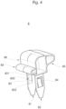
- FIG.4 a perspective view of a fixing device 8 of the busbar system according to the invention is shown.
- the fixing device 8 has a base 80 with at least one locking element 85, 85' arranged thereon.
- the fixing device 8 is designed such that two locking elements 85, 85' are arranged on the base 80.
- the locking elements 85, 85' of the fixing device 8 are arranged opposite one another on the base 80.
- the first locking element 85 overlaps the busbar.
- the second locking element 85' of the fixing device 8 is dimensioned and positioned such that it engages over at least one free end of the cover element in a fixing manner.
- the fixing device 8 of the busbar system according to the invention is designed such that it can be arranged in the respective holding element of the spacer offset by only 180°, so as to cover a free end of the cover element and/or the busbar in a fixing manner.
- the fixing device 8 is further designed such that it has at least one fixing web 81, 82 arranged on the base 80.
- the fixing device 8 of the busbar system according to the invention is designed such that it has two fixing webs 81, 82 arranged opposite one another on the base 80.
- the width of the fixing webs 81, 82 of the fixing device 8 is selected such that it corresponds approximately to the distance between the holding web 6 of the holding element 6 and the side wall 63 of the cross member 64 of the spacer (not shown).
- the fixing device 8 is further designed such that it has two fixing elements 83, 84 arranged opposite one another on the fixing webs 81, 82.
- a first fixing element 83 on the first fixing web 81 is designed such that it has a base 830 at the free ends of which a run-on bevel 831, 832 is arranged.
- the second fixing element 84 on the second fixing web 82 is designed as a locking hook in this embodiment.
- the fixing device 8 is further designed such that the fixing element 83, 84 arranged on the fixing web 81, 82 is arranged at a distance from the base 80.
- the fixing device 8 is made of a polymeric material, a polyamide (PA).
- the fixing device 8 is arranged on the holding element 6 of the spacer 3 in such a way that the fixing element 83, 84 engages behind the receiving opening 61 of the holding element 6 in a locking manner.
Landscapes
- Engineering & Computer Science (AREA)
- Mechanical Engineering (AREA)
- Clamps And Clips (AREA)
- Patch Boards (AREA)
- Insertion Pins And Rivets (AREA)
Claims (7)
- Système de rail conducteur, comprenant au moins un rail conducteur (1), au moins un élément de recouvrement (2) ainsi qu'au moins un élément d'écartement (3) pour le maintien espacé de l'élément de recouvrement (2) par rapport au rail conducteur (1), l'élément d'écartement (3) présentant au moins un élément d'encliquetage (31, 32), qui coopère avec au moins un élément de serrage (21, 22) de l'élément de recouvrement (2) en reliant ceux-ci, un élément de support (7) présentant une extrémité libre (5) qui recouvre le rail conducteur (1) et est disposée à distance de celui-ci, l'extrémité libre (5) de l'élément de support (7) étant disposée opposée au rail conducteur (1), l'élément d'écartement (3) étant formé par l'élément de support (7) relié à un élément de retenue (6, 6') par le biais d'une traverse (4, 9), l'élément d'écartement (3) présentant un dispositif de fixation (8), qui chevauche au moins une extrémité libre (23) de l'élément de recouvrement (2) et/ou le rail conducteur (1) tout en les fixant, ledit dispositif de fixation présentant une base (80) et coopérant avec l'élément d'écartement (3) par le biais d'au moins un élément de fixation (83, 84), le dispositif de fixation (8) présentant deux barrettes de fixation (81, 82) disposées opposées l'une à l'autre sur la base (80), le dispositif de fixation (8) présentant deux éléments de fixation (83, 84) disposés opposés l'un à l'autre sur les barrettes de fixation (81, 82), et qui viennent en prise par derrière en s'encliquetant dans au moins un orifice de réception (61) de l'élément de retenue (6, 6') de l'élément d'écartement (3), caractérisé en ce que
l'élément de retenue (6) présente une base (60) ainsi que deux orifices de réception (61) disposés l'un à côté de l'autre, en ce que deux barrettes de retenue (62) sont disposées sur le côté de l'élément de retenue (6) disposé opposé à la paroi latérale (93) de la traverse (9), en ce que la largeur des barrettes de fixation (81, 82) du dispositif de fixation (8) est sélectionnée de façon à correspondre approximativement à la distance entre la barrette de retenue (62) de l'élément de retenue (6, 6') et la paroi latérale (63) de la traverse (64) de l'élément d'écartement (3), et en ce qu'un des éléments de fixation (84) est réalisé sur l'une des barrettes de fixation (81, 82) sous la forme d'un crochet d'encliquetage. - Système de rail conducteur selon la revendication 1, caractérisé en ce que l'élément d'écartement (3), le dispositif de fixation (8) ainsi que l'élément de recouvrement (2) sont fabriqués dans des matériaux polymères et/ou thermodurcissables.
- Système de rail conducteur selon l'une des revendications précédentes, caractérisé en ce que le dispositif de fixation (8) est réalisé de telle sorte que l'élément de fixation (83, 84) disposé sur la barrette de fixation (81, 82) est disposé à distance de la base (80).
- Système de rail conducteur selon l'une des revendications précédentes, caractérisé en ce qu'un premier élément de fixation (83) est réalisé sur la première barrette de fixation (81) du dispositif de fixation (8) de façon à présenter une base (830), à l'extrémité libre de laquelle est respectivement disposée une inclinaison d'entrée (831, 832).
- Système de rail conducteur selon l'une des revendications précédentes, caractérisé en ce qu'au moins un élément de support (7) présente une extrémité libre (5) recouvrant l'élément formant surface de glissement (11) du rail conducteur (1) et disposée à distance de celui-ci et en ce que l'extrémité libre (5) de l'élément de support (7) est disposée opposée à l'élément formant surface de glissement (11) du rail conducteur (1).
- Système de rail conducteur selon l'une des revendications précédentes, caractérisé en ce que l'élément de serrage (21, 22) de l'élément de recouvrement (2) vient en prise par derrière en s'encliquetant dans au moins un élément d'encliquetage (31, 32) de l'élément d'écartement (3).
- Système de rail conducteur selon l'une des revendications précédentes, caractérisé en ce que la traverse (4, 9) et/ou l'élément de support (7) est réalisé approximativement en forme de double T en section transversale.
Applications Claiming Priority (1)
| Application Number | Priority Date | Filing Date | Title |
|---|---|---|---|
| DE202017101189.5U DE202017101189U1 (de) | 2017-03-02 | 2017-03-02 | Stromschienensystem |
Publications (2)
| Publication Number | Publication Date |
|---|---|
| EP3369609A1 EP3369609A1 (fr) | 2018-09-05 |
| EP3369609B1 true EP3369609B1 (fr) | 2024-07-31 |
Family
ID=61192761
Family Applications (1)
| Application Number | Title | Priority Date | Filing Date |
|---|---|---|---|
| EP18156238.0A Active EP3369609B1 (fr) | 2017-03-02 | 2018-02-12 | Système de rail conducteur |
Country Status (2)
| Country | Link |
|---|---|
| EP (1) | EP3369609B1 (fr) |
| DE (1) | DE202017101189U1 (fr) |
Families Citing this family (4)
| Publication number | Priority date | Publication date | Assignee | Title |
|---|---|---|---|---|
| USD1036303S1 (en) | 2017-05-03 | 2024-07-23 | Richard Steininger | Protection board mounting bracket |
| USD927354S1 (en) * | 2017-05-03 | 2021-08-10 | Richard Steininger | Protection board mounting bracket |
| USD957988S1 (en) * | 2017-05-03 | 2022-07-19 | Richard Steininger | Protection board mounting bracket |
| DE202018104720U1 (de) * | 2018-08-16 | 2019-11-19 | Rehau Ag + Co | Stromschienensystem |
Family Cites Families (10)
| Publication number | Priority date | Publication date | Assignee | Title |
|---|---|---|---|---|
| US3575576A (en) * | 1969-04-01 | 1971-04-20 | Johan L Harmsen | Power rail support and shield |
| US3614340A (en) * | 1969-10-17 | 1971-10-19 | Johan L Harmsen | Securing means for power rail and/or shield |
| DE7016606U (de) | 1970-05-02 | 1970-10-01 | Rehau Plastiks | Stromschienenabdeckung. |
| DE7018332U (de) | 1970-05-16 | 1970-08-06 | Rehau Plastiks | Stromschienenabdeckung. |
| US3806672A (en) * | 1972-10-13 | 1974-04-23 | Landis Sales Co | Third rail cover board |
| US4318462A (en) * | 1980-08-08 | 1982-03-09 | The Budd Company | Contact rail bracket |
| DE19912822C2 (de) * | 1999-03-22 | 2001-03-22 | Siemens Ag | Stromschienenträger |
| US7926634B1 (en) * | 2008-09-03 | 2011-04-19 | Miguel Angel Morales | Third rail power insulating system |
| DE202009017145U1 (de) * | 2009-12-19 | 2011-04-28 | Rehau Ag + Co. | Abstandshalter für Stromschienensystem |
| DE202012101576U1 (de) * | 2012-04-27 | 2013-07-30 | Rehau Ag + Co | Abstandshalter für ein Stromschienensystem |
-
2017
- 2017-03-02 DE DE202017101189.5U patent/DE202017101189U1/de not_active Expired - Lifetime
-
2018
- 2018-02-12 EP EP18156238.0A patent/EP3369609B1/fr active Active
Also Published As
| Publication number | Publication date |
|---|---|
| EP3369609A1 (fr) | 2018-09-05 |
| DE202017101189U1 (de) | 2018-06-05 |
Similar Documents
| Publication | Publication Date | Title |
|---|---|---|
| EP2657066B1 (fr) | Pièce intercalaire pour un système de barres conductrices | |
| EP3369609B1 (fr) | Système de rail conducteur | |
| EP2335967B1 (fr) | Pièce intercalaire pour système de barres conductrices | |
| DE102011113388A1 (de) | Schutzabdeckung | |
| DE102012018947A1 (de) | Befestigungselement, insbesondere Käfigmutter | |
| EP2695768B1 (fr) | Dispositif de fixation de rails | |
| EP3020903B1 (fr) | Support de capot | |
| DE202009017148U1 (de) | Abstandshalter für ein Stromschienensystem | |
| DE202009017147U1 (de) | Abstandshalter für ein Stromschienensystem | |
| EP2682555B1 (fr) | Elément de liaison d'angle | |
| EP3613627B1 (fr) | Système de rail conducteur | |
| EP3369608B1 (fr) | Système de rail conducteur | |
| DE102006036232A1 (de) | Schelle zur Fixierung strangförmiger Bauteile | |
| EP2639908B1 (fr) | Système de caniveaux de câbles | |
| EP2639905B1 (fr) | Système de caniveaux de câbles | |
| EP2639907B1 (fr) | Agencement de liaison pour éléments de caniveaux de câbles | |
| DE202011103129U1 (de) | Rastvorrichtung zur Befestigung von elektrischen Leitungen | |
| EP1111285B1 (fr) | Support | |
| DE202017105453U1 (de) | Wandanschlusssystem | |
| EP3444411B1 (fr) | Couvercle de protection pour un système de tubes profilés | |
| EP2639906B1 (fr) | Agencement de liaison pour systèmes de caniveaux de câbles | |
| DE202026100174U1 (de) | Verdrahtungskanal | |
| DE202012102136U1 (de) | Z-förmige Geräteeinbaukanal-Übergangsstückanordnung | |
| EP3339556A1 (fr) | Dispositif de fermeture pour composants | |
| DE102008007147A1 (de) | Klemmträgerprofil |
Legal Events
| Date | Code | Title | Description |
|---|---|---|---|
| PUAI | Public reference made under article 153(3) epc to a published international application that has entered the european phase |
Free format text: ORIGINAL CODE: 0009012 |
|
| STAA | Information on the status of an ep patent application or granted ep patent |
Free format text: STATUS: THE APPLICATION HAS BEEN PUBLISHED |
|
| AK | Designated contracting states |
Kind code of ref document: A1 Designated state(s): AL AT BE BG CH CY CZ DE DK EE ES FI FR GB GR HR HU IE IS IT LI LT LU LV MC MK MT NL NO PL PT RO RS SE SI SK SM TR |
|
| AX | Request for extension of the european patent |
Extension state: BA ME |
|
| STAA | Information on the status of an ep patent application or granted ep patent |
Free format text: STATUS: REQUEST FOR EXAMINATION WAS MADE |
|
| 17P | Request for examination filed |
Effective date: 20190304 |
|
| RBV | Designated contracting states (corrected) |
Designated state(s): AL AT BE BG CH CY CZ DE DK EE ES FI FR GB GR HR HU IE IS IT LI LT LU LV MC MK MT NL NO PL PT RO RS SE SI SK SM TR |
|
| STAA | Information on the status of an ep patent application or granted ep patent |
Free format text: STATUS: EXAMINATION IS IN PROGRESS |
|
| 17Q | First examination report despatched |
Effective date: 20191025 |
|
| RAP1 | Party data changed (applicant data changed or rights of an application transferred) |
Owner name: REHAU AG + CO |
|
| RAP1 | Party data changed (applicant data changed or rights of an application transferred) |
Owner name: REHAU INDUSTRIES SE & CO. KG |
|
| RAP3 | Party data changed (applicant data changed or rights of an application transferred) |
Owner name: REHAU INDUSTRIES SE & CO. KG |
|
| GRAP | Despatch of communication of intention to grant a patent |
Free format text: ORIGINAL CODE: EPIDOSNIGR1 |
|
| STAA | Information on the status of an ep patent application or granted ep patent |
Free format text: STATUS: GRANT OF PATENT IS INTENDED |
|
| GRAS | Grant fee paid |
Free format text: ORIGINAL CODE: EPIDOSNIGR3 |
|
| RIC1 | Information provided on ipc code assigned before grant |
Ipc: B60M 1/04 20060101ALN20240304BHEP Ipc: B60M 1/30 20060101AFI20240304BHEP |
|
| RIC1 | Information provided on ipc code assigned before grant |
Ipc: B60M 1/04 20060101ALN20240313BHEP Ipc: B60M 1/30 20060101AFI20240313BHEP |
|
| INTG | Intention to grant announced |
Effective date: 20240328 |
|
| GRAA | (expected) grant |
Free format text: ORIGINAL CODE: 0009210 |
|
| STAA | Information on the status of an ep patent application or granted ep patent |
Free format text: STATUS: THE PATENT HAS BEEN GRANTED |
|
| AK | Designated contracting states |
Kind code of ref document: B1 Designated state(s): AL AT BE BG CH CY CZ DE DK EE ES FI FR GB GR HR HU IE IS IT LI LT LU LV MC MK MT NL NO PL PT RO RS SE SI SK SM TR |
|
| REG | Reference to a national code |
Ref country code: CH Ref legal event code: EP Ref country code: GB Ref legal event code: FG4D Free format text: NOT ENGLISH |
|
| REG | Reference to a national code |
Ref country code: DE Ref legal event code: R096 Ref document number: 502018014924 Country of ref document: DE |
|
| REG | Reference to a national code |
Ref country code: IE Ref legal event code: FG4D Free format text: LANGUAGE OF EP DOCUMENT: GERMAN |
|
| REG | Reference to a national code |
Ref country code: LT Ref legal event code: MG9D |
|
| REG | Reference to a national code |
Ref country code: NL Ref legal event code: MP Effective date: 20240731 |
|
| PG25 | Lapsed in a contracting state [announced via postgrant information from national office to epo] |
Ref country code: PT Free format text: LAPSE BECAUSE OF FAILURE TO SUBMIT A TRANSLATION OF THE DESCRIPTION OR TO PAY THE FEE WITHIN THE PRESCRIBED TIME-LIMIT Effective date: 20241202 |
|
| PG25 | Lapsed in a contracting state [announced via postgrant information from national office to epo] |
Ref country code: PT Free format text: LAPSE BECAUSE OF FAILURE TO SUBMIT A TRANSLATION OF THE DESCRIPTION OR TO PAY THE FEE WITHIN THE PRESCRIBED TIME-LIMIT Effective date: 20241202 |
|
| PG25 | Lapsed in a contracting state [announced via postgrant information from national office to epo] |
Ref country code: NO Free format text: LAPSE BECAUSE OF FAILURE TO SUBMIT A TRANSLATION OF THE DESCRIPTION OR TO PAY THE FEE WITHIN THE PRESCRIBED TIME-LIMIT Effective date: 20241031 |
|
| PG25 | Lapsed in a contracting state [announced via postgrant information from national office to epo] |
Ref country code: FI Free format text: LAPSE BECAUSE OF FAILURE TO SUBMIT A TRANSLATION OF THE DESCRIPTION OR TO PAY THE FEE WITHIN THE PRESCRIBED TIME-LIMIT Effective date: 20240731 Ref country code: NL Free format text: LAPSE BECAUSE OF FAILURE TO SUBMIT A TRANSLATION OF THE DESCRIPTION OR TO PAY THE FEE WITHIN THE PRESCRIBED TIME-LIMIT Effective date: 20240731 Ref country code: PL Free format text: LAPSE BECAUSE OF FAILURE TO SUBMIT A TRANSLATION OF THE DESCRIPTION OR TO PAY THE FEE WITHIN THE PRESCRIBED TIME-LIMIT Effective date: 20240731 Ref country code: GR Free format text: LAPSE BECAUSE OF FAILURE TO SUBMIT A TRANSLATION OF THE DESCRIPTION OR TO PAY THE FEE WITHIN THE PRESCRIBED TIME-LIMIT Effective date: 20241101 |
|
| PG25 | Lapsed in a contracting state [announced via postgrant information from national office to epo] |
Ref country code: BG Free format text: LAPSE BECAUSE OF FAILURE TO SUBMIT A TRANSLATION OF THE DESCRIPTION OR TO PAY THE FEE WITHIN THE PRESCRIBED TIME-LIMIT Effective date: 20240731 |
|
| PG25 | Lapsed in a contracting state [announced via postgrant information from national office to epo] |
Ref country code: LV Free format text: LAPSE BECAUSE OF FAILURE TO SUBMIT A TRANSLATION OF THE DESCRIPTION OR TO PAY THE FEE WITHIN THE PRESCRIBED TIME-LIMIT Effective date: 20240731 |
|
| PG25 | Lapsed in a contracting state [announced via postgrant information from national office to epo] |
Ref country code: IS Free format text: LAPSE BECAUSE OF FAILURE TO SUBMIT A TRANSLATION OF THE DESCRIPTION OR TO PAY THE FEE WITHIN THE PRESCRIBED TIME-LIMIT Effective date: 20241130 |
|
| PG25 | Lapsed in a contracting state [announced via postgrant information from national office to epo] |
Ref country code: HR Free format text: LAPSE BECAUSE OF FAILURE TO SUBMIT A TRANSLATION OF THE DESCRIPTION OR TO PAY THE FEE WITHIN THE PRESCRIBED TIME-LIMIT Effective date: 20240731 |
|
| PG25 | Lapsed in a contracting state [announced via postgrant information from national office to epo] |
Ref country code: ES Free format text: LAPSE BECAUSE OF FAILURE TO SUBMIT A TRANSLATION OF THE DESCRIPTION OR TO PAY THE FEE WITHIN THE PRESCRIBED TIME-LIMIT Effective date: 20240731 Ref country code: RS Free format text: LAPSE BECAUSE OF FAILURE TO SUBMIT A TRANSLATION OF THE DESCRIPTION OR TO PAY THE FEE WITHIN THE PRESCRIBED TIME-LIMIT Effective date: 20241031 |
|
| PG25 | Lapsed in a contracting state [announced via postgrant information from national office to epo] |
Ref country code: RS Free format text: LAPSE BECAUSE OF FAILURE TO SUBMIT A TRANSLATION OF THE DESCRIPTION OR TO PAY THE FEE WITHIN THE PRESCRIBED TIME-LIMIT Effective date: 20241031 Ref country code: PL Free format text: LAPSE BECAUSE OF FAILURE TO SUBMIT A TRANSLATION OF THE DESCRIPTION OR TO PAY THE FEE WITHIN THE PRESCRIBED TIME-LIMIT Effective date: 20240731 Ref country code: NO Free format text: LAPSE BECAUSE OF FAILURE TO SUBMIT A TRANSLATION OF THE DESCRIPTION OR TO PAY THE FEE WITHIN THE PRESCRIBED TIME-LIMIT Effective date: 20241031 Ref country code: NL Free format text: LAPSE BECAUSE OF FAILURE TO SUBMIT A TRANSLATION OF THE DESCRIPTION OR TO PAY THE FEE WITHIN THE PRESCRIBED TIME-LIMIT Effective date: 20240731 Ref country code: LV Free format text: LAPSE BECAUSE OF FAILURE TO SUBMIT A TRANSLATION OF THE DESCRIPTION OR TO PAY THE FEE WITHIN THE PRESCRIBED TIME-LIMIT Effective date: 20240731 Ref country code: IS Free format text: LAPSE BECAUSE OF FAILURE TO SUBMIT A TRANSLATION OF THE DESCRIPTION OR TO PAY THE FEE WITHIN THE PRESCRIBED TIME-LIMIT Effective date: 20241130 Ref country code: HR Free format text: LAPSE BECAUSE OF FAILURE TO SUBMIT A TRANSLATION OF THE DESCRIPTION OR TO PAY THE FEE WITHIN THE PRESCRIBED TIME-LIMIT Effective date: 20240731 Ref country code: GR Free format text: LAPSE BECAUSE OF FAILURE TO SUBMIT A TRANSLATION OF THE DESCRIPTION OR TO PAY THE FEE WITHIN THE PRESCRIBED TIME-LIMIT Effective date: 20241101 Ref country code: FI Free format text: LAPSE BECAUSE OF FAILURE TO SUBMIT A TRANSLATION OF THE DESCRIPTION OR TO PAY THE FEE WITHIN THE PRESCRIBED TIME-LIMIT Effective date: 20240731 Ref country code: ES Free format text: LAPSE BECAUSE OF FAILURE TO SUBMIT A TRANSLATION OF THE DESCRIPTION OR TO PAY THE FEE WITHIN THE PRESCRIBED TIME-LIMIT Effective date: 20240731 Ref country code: BG Free format text: LAPSE BECAUSE OF FAILURE TO SUBMIT A TRANSLATION OF THE DESCRIPTION OR TO PAY THE FEE WITHIN THE PRESCRIBED TIME-LIMIT Effective date: 20240731 |
|
| PG25 | Lapsed in a contracting state [announced via postgrant information from national office to epo] |
Ref country code: DK Free format text: LAPSE BECAUSE OF FAILURE TO SUBMIT A TRANSLATION OF THE DESCRIPTION OR TO PAY THE FEE WITHIN THE PRESCRIBED TIME-LIMIT Effective date: 20240731 Ref country code: SM Free format text: LAPSE BECAUSE OF FAILURE TO SUBMIT A TRANSLATION OF THE DESCRIPTION OR TO PAY THE FEE WITHIN THE PRESCRIBED TIME-LIMIT Effective date: 20240731 Ref country code: RO Free format text: LAPSE BECAUSE OF FAILURE TO SUBMIT A TRANSLATION OF THE DESCRIPTION OR TO PAY THE FEE WITHIN THE PRESCRIBED TIME-LIMIT Effective date: 20240731 |
|
| PG25 | Lapsed in a contracting state [announced via postgrant information from national office to epo] |
Ref country code: EE Free format text: LAPSE BECAUSE OF FAILURE TO SUBMIT A TRANSLATION OF THE DESCRIPTION OR TO PAY THE FEE WITHIN THE PRESCRIBED TIME-LIMIT Effective date: 20240731 |
|
| PG25 | Lapsed in a contracting state [announced via postgrant information from national office to epo] |
Ref country code: CZ Free format text: LAPSE BECAUSE OF FAILURE TO SUBMIT A TRANSLATION OF THE DESCRIPTION OR TO PAY THE FEE WITHIN THE PRESCRIBED TIME-LIMIT Effective date: 20240731 |
|
| PG25 | Lapsed in a contracting state [announced via postgrant information from national office to epo] |
Ref country code: IT Free format text: LAPSE BECAUSE OF FAILURE TO SUBMIT A TRANSLATION OF THE DESCRIPTION OR TO PAY THE FEE WITHIN THE PRESCRIBED TIME-LIMIT Effective date: 20240731 Ref country code: SK Free format text: LAPSE BECAUSE OF FAILURE TO SUBMIT A TRANSLATION OF THE DESCRIPTION OR TO PAY THE FEE WITHIN THE PRESCRIBED TIME-LIMIT Effective date: 20240731 |
|
| REG | Reference to a national code |
Ref country code: DE Ref legal event code: R097 Ref document number: 502018014924 Country of ref document: DE |
|
| PLBE | No opposition filed within time limit |
Free format text: ORIGINAL CODE: 0009261 |
|
| STAA | Information on the status of an ep patent application or granted ep patent |
Free format text: STATUS: NO OPPOSITION FILED WITHIN TIME LIMIT |
|
| 26N | No opposition filed |
Effective date: 20250501 |
|
| PG25 | Lapsed in a contracting state [announced via postgrant information from national office to epo] |
Ref country code: SE Free format text: LAPSE BECAUSE OF FAILURE TO SUBMIT A TRANSLATION OF THE DESCRIPTION OR TO PAY THE FEE WITHIN THE PRESCRIBED TIME-LIMIT Effective date: 20240731 |
|
| PG25 | Lapsed in a contracting state [announced via postgrant information from national office to epo] |
Ref country code: MC Free format text: LAPSE BECAUSE OF FAILURE TO SUBMIT A TRANSLATION OF THE DESCRIPTION OR TO PAY THE FEE WITHIN THE PRESCRIBED TIME-LIMIT Effective date: 20240731 |
|
| REG | Reference to a national code |
Ref country code: CH Ref legal event code: PL |
|
| PG25 | Lapsed in a contracting state [announced via postgrant information from national office to epo] |
Ref country code: LU Free format text: LAPSE BECAUSE OF NON-PAYMENT OF DUE FEES Effective date: 20250212 |
|
| PG25 | Lapsed in a contracting state [announced via postgrant information from national office to epo] |
Ref country code: CH Free format text: LAPSE BECAUSE OF NON-PAYMENT OF DUE FEES Effective date: 20250228 |
|
| GBPC | Gb: european patent ceased through non-payment of renewal fee |
Effective date: 20250212 |
|
| REG | Reference to a national code |
Ref country code: BE Ref legal event code: MM Effective date: 20250228 |
|
| PG25 | Lapsed in a contracting state [announced via postgrant information from national office to epo] |
Ref country code: GB Free format text: LAPSE BECAUSE OF NON-PAYMENT OF DUE FEES Effective date: 20250212 |
|
| PG25 | Lapsed in a contracting state [announced via postgrant information from national office to epo] |
Ref country code: BE Free format text: LAPSE BECAUSE OF NON-PAYMENT OF DUE FEES Effective date: 20250228 |
|
| PG25 | Lapsed in a contracting state [announced via postgrant information from national office to epo] |
Ref country code: IE Free format text: LAPSE BECAUSE OF NON-PAYMENT OF DUE FEES Effective date: 20250212 |
|
| PGFP | Annual fee paid to national office [announced via postgrant information from national office to epo] |
Ref country code: DE Payment date: 20260228 Year of fee payment: 9 |
|
| PG25 | Lapsed in a contracting state [announced via postgrant information from national office to epo] |
Ref country code: AT Free format text: LAPSE BECAUSE OF NON-PAYMENT OF DUE FEES Effective date: 20250212 |
|
| REG | Reference to a national code |
Ref country code: AT Ref legal event code: MM01 Ref document number: 1708165 Country of ref document: AT Kind code of ref document: T Effective date: 20250212 |
|
| PGFP | Annual fee paid to national office [announced via postgrant information from national office to epo] |
Ref country code: FR Payment date: 20260203 Year of fee payment: 9 |
|
| PGFP | Annual fee paid to national office [announced via postgrant information from national office to epo] |
Ref country code: TR Payment date: 20260205 Year of fee payment: 9 |