EP3369685A1 - Dispositif de transport de pièces allongées à un point de réception et de dépôt des dites pièces allongées audit point de réception - Google Patents
Dispositif de transport de pièces allongées à un point de réception et de dépôt des dites pièces allongées audit point de réception Download PDFInfo
- Publication number
- EP3369685A1 EP3369685A1 EP18158899.7A EP18158899A EP3369685A1 EP 3369685 A1 EP3369685 A1 EP 3369685A1 EP 18158899 A EP18158899 A EP 18158899A EP 3369685 A1 EP3369685 A1 EP 3369685A1
- Authority
- EP
- European Patent Office
- Prior art keywords
- brush
- workpieces
- section
- pair
- brush belt
- Prior art date
- Legal status (The legal status is an assumption and is not a legal conclusion. Google has not performed a legal analysis and makes no representation as to the accuracy of the status listed.)
- Withdrawn
Links
- 238000000151 deposition Methods 0.000 title claims abstract 3
- 238000005520 cutting process Methods 0.000 claims description 10
- 238000001816 cooling Methods 0.000 claims description 9
- 238000003825 pressing Methods 0.000 claims description 2
- 238000007639 printing Methods 0.000 description 7
- 238000006073 displacement reaction Methods 0.000 description 5
- 238000003780 insertion Methods 0.000 description 5
- 230000037431 insertion Effects 0.000 description 5
- 238000003860 storage Methods 0.000 description 4
- 238000000034 method Methods 0.000 description 2
- 230000000712 assembly Effects 0.000 description 1
- 238000000429 assembly Methods 0.000 description 1
- 230000000903 blocking effect Effects 0.000 description 1
- 238000010276 construction Methods 0.000 description 1
- 238000007599 discharging Methods 0.000 description 1
- 238000005516 engineering process Methods 0.000 description 1
- 238000004519 manufacturing process Methods 0.000 description 1
- 230000002093 peripheral effect Effects 0.000 description 1
- 230000000284 resting effect Effects 0.000 description 1
- 230000001360 synchronised effect Effects 0.000 description 1
Images




Classifications
-
- B—PERFORMING OPERATIONS; TRANSPORTING
- B65—CONVEYING; PACKING; STORING; HANDLING THIN OR FILAMENTARY MATERIAL
- B65G—TRANSPORT OR STORAGE DEVICES, e.g. CONVEYORS FOR LOADING OR TIPPING, SHOP CONVEYOR SYSTEMS OR PNEUMATIC TUBE CONVEYORS
- B65G57/00—Stacking of articles
- B65G57/02—Stacking of articles by adding to the top of the stack
- B65G57/16—Stacking of articles of particular shape
- B65G57/18—Stacking of articles of particular shape elongated, e.g. sticks, rods, bars
- B65G57/186—Cylindrical articles, e.g. tubes, rods, etc.
-
- B—PERFORMING OPERATIONS; TRANSPORTING
- B21—MECHANICAL METAL-WORKING WITHOUT ESSENTIALLY REMOVING MATERIAL; PUNCHING METAL
- B21F—WORKING OR PROCESSING OF METAL WIRE
- B21F23/00—Feeding wire in wire-working machines or apparatus
- B21F23/005—Feeding discrete lengths of wire or rod
-
- B—PERFORMING OPERATIONS; TRANSPORTING
- B65—CONVEYING; PACKING; STORING; HANDLING THIN OR FILAMENTARY MATERIAL
- B65G—TRANSPORT OR STORAGE DEVICES, e.g. CONVEYORS FOR LOADING OR TIPPING, SHOP CONVEYOR SYSTEMS OR PNEUMATIC TUBE CONVEYORS
- B65G15/00—Conveyors having endless load-conveying surfaces, i.e. belts and like continuous members, to which tractive effort is transmitted by means other than endless driving elements of similar configuration
- B65G15/10—Conveyors having endless load-conveying surfaces, i.e. belts and like continuous members, to which tractive effort is transmitted by means other than endless driving elements of similar configuration comprising two or more co-operating endless surfaces with parallel longitudinal axes, or a multiplicity of parallel elements, e.g. ropes defining an endless surface
- B65G15/105—Conveyors having endless load-conveying surfaces, i.e. belts and like continuous members, to which tractive effort is transmitted by means other than endless driving elements of similar configuration comprising two or more co-operating endless surfaces with parallel longitudinal axes, or a multiplicity of parallel elements, e.g. ropes defining an endless surface the surface being formed by two or more ropes
-
- B—PERFORMING OPERATIONS; TRANSPORTING
- B65—CONVEYING; PACKING; STORING; HANDLING THIN OR FILAMENTARY MATERIAL
- B65G—TRANSPORT OR STORAGE DEVICES, e.g. CONVEYORS FOR LOADING OR TIPPING, SHOP CONVEYOR SYSTEMS OR PNEUMATIC TUBE CONVEYORS
- B65G21/00—Supporting or protective framework or housings for endless load-carriers or traction elements of belt or chain conveyors
- B65G21/10—Supporting or protective framework or housings for endless load-carriers or traction elements of belt or chain conveyors movable, or having interchangeable or relatively movable parts; Devices for moving framework or parts thereof
-
- B—PERFORMING OPERATIONS; TRANSPORTING
- B65—CONVEYING; PACKING; STORING; HANDLING THIN OR FILAMENTARY MATERIAL
- B65G—TRANSPORT OR STORAGE DEVICES, e.g. CONVEYORS FOR LOADING OR TIPPING, SHOP CONVEYOR SYSTEMS OR PNEUMATIC TUBE CONVEYORS
- B65G47/00—Article or material-handling devices associated with conveyors; Methods employing such devices
- B65G47/02—Devices for feeding articles or materials to conveyors
- B65G47/04—Devices for feeding articles or materials to conveyors for feeding articles
- B65G47/12—Devices for feeding articles or materials to conveyors for feeding articles from disorderly-arranged article piles or from loose assemblages of articles
- B65G47/14—Devices for feeding articles or materials to conveyors for feeding articles from disorderly-arranged article piles or from loose assemblages of articles arranging or orientating the articles by mechanical or pneumatic means during feeding
- B65G47/1407—Devices for feeding articles or materials to conveyors for feeding articles from disorderly-arranged article piles or from loose assemblages of articles arranging or orientating the articles by mechanical or pneumatic means during feeding the articles being fed from a container, e.g. a bowl
- B65G47/1442—Devices for feeding articles or materials to conveyors for feeding articles from disorderly-arranged article piles or from loose assemblages of articles arranging or orientating the articles by mechanical or pneumatic means during feeding the articles being fed from a container, e.g. a bowl by means of movement of the bottom or a part of the wall of the container
- B65G47/1471—Movement in one direction, substantially outwards
-
- B—PERFORMING OPERATIONS; TRANSPORTING
- B65—CONVEYING; PACKING; STORING; HANDLING THIN OR FILAMENTARY MATERIAL
- B65G—TRANSPORT OR STORAGE DEVICES, e.g. CONVEYORS FOR LOADING OR TIPPING, SHOP CONVEYOR SYSTEMS OR PNEUMATIC TUBE CONVEYORS
- B65G69/00—Auxiliary measures taken, or devices used, in connection with loading or unloading
- B65G69/16—Preventing pulverisation, deformation, breakage, or other mechanical damage to the goods or materials
- B65G69/165—Preventing pulverisation, deformation, breakage, or other mechanical damage to the goods or materials using descending or lowering endless conveyors
Definitions
- the invention relates to a device for transporting elongated workpieces to a receiving location and for storage at this, with a transport path, which comprises a first and at least one further downstream of this web section, wherein the first web section is associated with a workpiece feed.
- Devices for transporting elongated workpieces are known in many different embodiments (such as DE 10 2010 012 612 B3 . DE 10 2013 206 655 B3 . DE 31 43 269 A1 ).
- each of the downstream track sections comprises an endless toothed belt, which is driven via an associated belt pulley and to which a guide rail is assigned.
- the toothed belts of the at least two downstream web sections are laterally offset from one another by the width of one pulley, wherein the workpieces conveyed by a toothed belt are taken over by the other toothed belt for onward transport within a transfer station.
- each belt workpiece protrude with its peripheral lateral surface slightly beyond the height of the receiving recess of the toothed belt delimiting teeth, wherein the workpiece rests in this projecting region on top of the guide rail and slides during transport along the guide rail on this.
- This known transport arrangement makes it possible to realize transport paths over a very long length while also providing along the transport path a change in direction of the transport direction.
- this known device is relatively expensive because of the assignment of guide rails to the transport paths and the lateral offset of successive track sections and this taking into account transfer stations.
- the known device is also not suitable to store the transported workpieces position-oriented at a receiving location.
- the invention is intended to provide a device for transporting elongate workpieces, which is suitable in particular for transporting short bars (150 mm - 250 mm in length) over relatively short distances and by means of which these workpieces can be stored in a position-oriented manner at a receiving location.
- a device of the type mentioned with a base frame on which the first web portion is pivotally mounted at its rear end in the conveying direction end about a frame-fixed axis, wherein the web sections with their mutually facing end regions in each case by a common joint point relative each track section having a straight run, each having a deflection point at its two ends, all brush belt pairs are driven synchronously and at each joint between two track sections the workpieces to be transported from the brush belt Pair of the preceding track section are transferred to that of the following track section, and with an end of the last track section downstream ejector unit, where the conveyed workpieces via a scraper single n removed from the brush belt pair of the last track section and stored at the pick-up location oriented.
- the track sections with their mutually facing end areas about a common joint pivotally to each other, so that their relative orientation to each other can be changed continuously, at the end of the last track section arriving there, from the scraper from the brush belt pair of this track section To be able to deposit removed workpieces at the pick-up location.
- the end of the last web section at the receiving location can be brought to mutually offset dispensing points and thus a location-oriented workpieces can be deposited.
- the device according to the invention is comparatively simple in construction and presents itself as a cost-effective alternative to the use of a robot.
- short rods for. B. 150 mm to 250 mm long, in a diameter range of 3 mm to 7 mm with a high output of z. B. up to 180 pieces per minute (or even more) are transported.
- the workpiece feeder is provided on the first web portion with a push-in for pressing the delivered workpieces into the brushes of the brush belt pair of the first web section, wherein, again preferred, the impressions of the workpieces in the brushes the brush belt pair of the first web portion is carried out while the drive motor is running and an intermittent actuation thereof is not required.
- a hold-down device is provided at the inlet of the first web section as well as at the outlet of all following web sections, by means of which the workpieces are held in the region of the respective deflection point there in the orbit.
- a particularly preferred embodiment of the invention also consists in that along the straight run of all track sections of each brush belt of the same is assigned a guide plate which covers the workpieces to be transported laterally and at the top at least partially, while holding in the brushes. In this way, the inclusion of the workpieces in the brush belt of each pair of brush belts ensures very effective with simple measures.
- the base frame yet another adjustment is attached, which fixed to the frame with one end, but pivotally mounted and is hinged at its other end to the housing of the first adjustment.
- the angle adjustment of the first adjustment relative to their bearing on the base frame can also be quickly and easily set or change.
- adjusting pressure cylinders in particular in the form of compressed air cylinders or as electric cylinders, are used.
- rack assemblies spindles, servo axes o. ⁇ . Can be used as a suitable adjustment.
- a further preferred embodiment of the device according to the invention consists in the fact that in the region of the joint joint in each case two successive track sections on the upper side of the brush belt pair of the following web section each brush belt is assigned a spring band, which is connected at its two ends to a respective spring-biased roller chain and thereby in each relative pivoting position of both track sections to each other, the pivot point is circumferentially held in position. This ensures that both in the area of transfer of the workpieces from the one web section to the next web section, as well as along the same after the deflection point, the workpieces are again securely held within the pair of brush belts of the following web section.
- a funnel-shaped passage for positionally oriented introduction of the workpieces is provided between the Abgabeklappen so that at each detached from the brush belt pair of the last track section by the scraper workpiece due to the funnel-shaped Design of the passage to the dispensing flaps towards a position-oriented and automatically centered in the dispensing flap arrangement takes place.
- the brush belts of the brush belt pair of the second web portion are spaced from each other by a smaller distance than the brush belt of the brush belt pair of the first web portion, wherein they are aligned centrally to the latter, which in total in the width of the device can achieve compact design.
- a preferred embodiment of the invention also consists in that a central control device for controlling all motors, the adjusting devices and the workpiece feed, and possibly further linear or pivoting movements of individual elements of the device, is provided.
- the common hinge point of the first and second track section comprises a central rotary shaft, are mounted on the drive wheels for the brush belt of the brush belt pairs of both track sections and which is connected to a laterally arranged drive motor. Any suitable drive motor can be used. In this way, it is ensured by the drive of the brush belt pairs at this joint joint that the workpieces are also moved synchronously across the hinge point.
- a device which is adapted to be able to adjust the distance between the brush belt of the brush belt pairs on the first web section, wherein, again preferred, a handwheel for adjusting this distance is used.
- this device When the distance between the pair of brush belts of the first web section is adjusted by this device, this means that at the same time a corresponding adjustment in the joint joint occurs, but at the same time there is a deflection point of the pair of brush belt of the second web section, so that There is also associated with the changed distance between the brush belt of the brush belt pair of the first web portion and a change in the distance between the brush belt of the brush belt pair of the second web section simultaneously.
- the device makes a change in the spacing of the brush belts of the brush belt pair of the first web section, a suitable change in the spacing between the brush belts of the brush belt pair of the second web section takes place at the same time.
- the device according to the invention makes it possible to transport over a transport path with multiple track sections away short workpieces and these at a receiving location, for. B. in a receptacle or a frame, position-oriented store, the deposit can be selected vertically and horizontally targeted. If not only a stacking of the workpieces in the vertical direction, it is possible to move the receiving site in turn laterally so that adjacent workpiece stack can be stored on her.
- the device according to the invention can be designed with two, three or even more track sections, but preferably two or even three track sections are selected.
- a portal can preferably also be provided on which a printing cylinder unit is mounted, which is movably mounted on the portal with its one end and articulated at its other end on the last web section, preferably on the last web section near the ejector unit.
- the workpiece feed is preceded by a wire straightening and cutting machine for feeding the elongate workpieces.
- a track section or several track sections are provided with cooling units, which are preferably designed as integrated fans.
- cooling units which are preferably designed as integrated fans.
- inventive devices are shown, which are associated with a wire straightening machine with a cutting station, wherein in all figures the same parts are provided with the same reference numerals.
- Fig. 1 shows a perspective perspective view of a wire straightening machine 1, which is provided at its front with a cutting station 2.
- This wire straightening machine 1 is supplied with wire from a coil (not shown), directed in it and then in the cutting station 2 in short, elongate workpieces 10 (see. Fig. 3 ) in the form of rods or pipe sections with a length of z.
- the arrangement is associated with an attachment 3, which receives the supplied from the wire straightening machine 1 and the cutting station 2 cut and directed rods and from which they slip into a workpiece feed 4 of a transport device 5 according to the invention, which is provided with two track sections 6 and 14.
- the first track section 6 is followed by a second track section 14, wherein both track sections 6 and 14 are pivotally connected together at their mutually facing end portions via a common hinge point 15, from which the second track section 14 continues along a straight line to a further deflection point 53 ,
- An only very basic sectional view through this joint joint 15 shows Fig. 10 , wherein the cutting position is selected in a direction perpendicular to the longitudinal axis of the first path section 6 cutting plane.
- a drive motor 16 drives a drive shaft 17. On this, axially adjacent to each other, two radially enlarged in diameter and each cylindrical shaped receiving heights 18 and 19 are mounted, both of which are driven by the drive motor 16 via the drive shaft 17.
- the receiving shoulder 18 is firmly seated on the drive shaft 17, while the receiving shoulder 19 can be moved axially on the drive shaft 17, but always with this in the direction of rotation in positive engagement, so that even with an axial displacement always drive by the drive motor 16 at the receiving paragraph 19 remains effective.
- Fig. 10 shows, the brush belt 7 'and 7 "of the brush belt pair 7 of the first track section 6 axially outwardly on the drive shaft 17, while the brush belt 20' and 20" of the second pair of brush belt associated with the second web section 14 between the two brush belts 7 'and 7 ", centrally to these, are attached.
- FIG. 3 shows how individual workpieces 10 from the brush belt pair 7 of the first web section 6 (in FIG Fig. 3 only one of the brush belts 7 'can be seen), coming from the workpiece feed 4, in the direction of the other end of the first track section 6 to the local deflection point 12, which at the same time also represents the track sections 6 and 14 joint joint 15, are transported.
- the workpieces 10 are held at their respective lateral end portions in the brushes of the brush belt 7 'and 7 "(the latter covered by the cover 8) of the first pair of brush belts 7 and are guided by the synchronous forward movement of these brush belts to the deflection point 12.
- the brush belts 7 'and 7 "of the first pair of brush belts 7 pivot downwards at the point of deflection 12 and then back in the opposite direction, while the workpieces 10 pivot from the two brush belts 20' and 20" of the second pair of brush belts 20 be transported from there further in the longitudinal direction of the second path section 14.
- the brush belts 7 'and 7 "of the first pair of brush belts 7 and the brush belts 20' and 20" of the second pair of brush belts 20 are each designed as endlessly circulating, parallel to each other transport belts on their upper side are each occupied by a plurality of rows of adjacently mounted brush elements.
- a rod-shaped workpiece 10 is still detected at the deflection point 12 of the joint joint 15 at its outer end of the brush belt 7 'and 7 "of the first pair of brush belts 7 and until there was transported by these up to the point where the brush belt 20 'and 20 "of the second pair of brush belts 20, the there also, but in a first path section 6 downstream transport direction of the second web section 14, at the deflection point 12th rotates, being disposed axially between the two outer brush belts 7 'and 7 "of the first pair of brush belts.
- the conveyed by the first pair of brush belt 7 workpiece 10 runs in the area between the brush belt 7 'and 7 "in the circulating there brushes of the brush belt 20' and 20" of the second pair of brush belts 20 and is detected by these, wherein the Turning 12 the brush belt of the first pair of brush belt 7 and the second brush belt pair 20 rotate synchronously driven by the drive motor 16. Then, in their further rotation, the brush belts 7 'and 7 "swing in the opposite direction and run back to the workpiece feed 4, the axial end portions of the workpiece 10 are released from the brushes of the first pair of brush belts 7 and then only from the brush belt 20th 'and 20 "transported further, in the longitudinal direction of the second track section 14 to the ejector unit 21st
- the transport device 5 is further provided with a device 23 for adjusting the distance of the brush belt 7 'and 20' of the brush belt 7 "and 20" to adjust the transport device 5 to different lengths of the workpieces 10 can.
- a device 23 for adjusting the distance of the brush belt 7 'and 20' of the brush belt 7 "and 20" to adjust the transport device 5 to different lengths of the workpieces 10 can In this case, the axial distance between the brush belt 7 'of the first pair of brush belts 7 and the brush belt 20' of the second pair of brush belts as well as the axial distance between the brush belt 7 "and the brush belt 20" remains unchanged, it is through the device 23rd So basically only the distance between the two mentioned brush belt 7 'and 20' on the one hand and 7 "and 20" on the other hand changed.
- Fig. 12 is in an only schematic representation of the arrangement of the device 23 in its assignment to the first track section 6, in whose area it is mounted shown (while only constructive elements that promote understanding, quite basically indicated, in the case of a multiple arrangement of such constructive Elements each shown only one and the others are omitted for clarity).
- the device 23 first comprises a handwheel 24 for its operation by the operator.
- the hand wheel 24 is connected to a rotary shaft 25, which carries a displaceably mounted by the rotation of the handwheel 24 in the longitudinal direction of the rotary shaft 25 console 26, in turn, suitably fixed on its upper side with the, seen in the transport direction of the workpieces 10 left (first) cover 8 of the first web section 6 is connected. If, by turning the hand wheel 24, the bracket 26 is displaced in the longitudinal direction of the rotary shaft 25, this first cover 8, which covers the brush belt 7 "running inside it, is also displaced axially accordingly.
- the distance A by which the two brush belts 7 'and 7 "of the first pair of brush belts 7 are removed from each other, is changed in a corresponding manner.
- the hand wheel 24, the rotary shaft 25 and the sliding bracket 26 and the associated other elements that allow the support and displacement of the console 26, sitting on a bearing bracket 27, which in turn is mounted on a bearing block 28, which in turn provides a support against a base frame 38 represents.
- a Fixierflansch 29 is mounted perpendicular to this, which is rigidly secured to the second cover 8 in the region of the first track portion 6 in a suitable manner, such as by screws. This ensures that with a rotation of the handwheel 24 only one (seen in the transport direction of the workpieces: left) cover 8 can be moved with the running in this brush belt 7 "in the direction of the rotary shaft 25, the opposite other cover 8 with the there attached brush belt 7 ', however, undergoes no such linear longitudinal movement by its attachment to the fixing flange 29.
- Fig. 12 is, only in principle and only on the left side of the illustration, indicated that from the point axially adjacent to the brush belt 7 ', on which the brush belt 20' on the drive shaft 17 rotates and forms a side arm 30, within which the brush belt 20th 'extends and which extends along the second portion 14 (wherein a same side arm and from the second, sitting on the drive shaft 17 brush belt 20 "out, in Fig. 12 but not shown), with a certain distance from the drive shaft 17 of the joint joint 15, a guide pin 31 is mounted, which extends parallel to the drive shaft 17 and extends through both lateral arms 30 of the second web section 14 therethrough.
- a guide pin 31 is mounted, which extends parallel to the drive shaft 17 and extends through both lateral arms 30 of the second web section 14 therethrough.
- the lateral arm 30 opposite side arm of the second web portion 14 shown there is a receiving bore through which the guide pin 31 slidably protrudes, so that in an adjustment of the distance A by the handwheel 24 in the second path section 14th whose lateral arms 30 are guided during the displacement movement of one of the same over the guide pin 31, so that a total of a lateral displacement of the " left half " of the transport device 5 is given both a guide in the direction of displacement on the first path section 6, as well as on the second path section 14 ,
- the device 23 is designed so that after a successful adjustment of the distance A, a position blocking the sliding bracket 26, such as by a suitable clamping device (not shown in the drawing) is made to the set distance A for the operation of the transport device 5 unchanged maintain until a new adjustment is required.
- each of the brush belt 20 'and 20 "of the second pair of brush belt associated with 20 a respective movable spring band 33 and 34 attached radially outward to the circulating brush belt 20' and 20 "around and prevents the transported workpieces 10 could run out of orbit.
- the spring bands 33 and 34 are connected at their two ends to a resilient element: they are attached in the embodiment shown at each of its ends to a roller chain 35 and fixedly mounted on this to an elastic mounting block 36 on the second path section 6.
- the spring bands 33, 34 are also attached via a respective roller chain 35 to a spring element 37, so that the spring strips 33, 34 are always under a spring bias, which holds the respective spring band 33 and 34 in position and in principle so that corresponding spring band gives the same function as that of the blank holder 32 at the inlet of the first track section 6 and at the outlet of the second track section 14.
- the extendable piston rod 40 at a distance from the axis of rotation of the joint joint 15 of both track sections 6 and 14 on second track section 14 is hinged, as shown in the FIGS. 4 to 7 as well as the representation of the FIG. 12 is removable.
- the articulation point can preferably be provided on the guide pin 31.
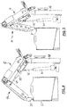
- a setting is shown in which, in contrast to Fig. 4 , the ejector unit 21 continues at the top of the receptacle 22, but at the position of the Fig. 4 offset from the opposite side of the receptacle 22, is arranged.
- the ejector unit 21 is lowered to the bottom of the receptacle 22 and although there to an end of the base frame 38 extended end position, as they Fig. 6 shows.
- Fig. 7 is the ejector unit 21 also lowered to the bottom of the receptacle 22, but spent in a position that the position of Fig. 6 opposite, ie at the lower end of the receptacle 22 is located.
- the positions of the printing cylinder at the different positions of the ejector unit 21 at the receiving location, the receptacle 22, depend on what is deposited accordingly in the central control.
- the transported workpieces 10 in the receptacle 22 store so that they can fill the entire cross section of the interior of the receptacle 22 in the context of a superimposed layer.
- the receptacle 22 in turn it laterally, ie perpendicular to the traversed by the movements of the track sections 6 and 14 level, is movable and thereby a appropriate storage of adjacent, superimposed workpieces 10 can be done.
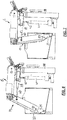
- the 8 and 9 now show an enlarged detail detail a structural design of the workpiece feed 4 at the inlet of the workpieces 10 in the first path section 6. It provides Fig. 8 the state, when a plurality of workpieces have entered the workpiece feed 4, and Fig. 9 shows the state after the foremost workpiece 10 is inserted into the brush belt 7 'or 7 "shown in the figure with only a white cross-section.
- the arrangement of the workpiece feed 4 initially comprises a deflection roller 43 running around the deflection point 11, on which a brush belt 7 'or 7 "runs around the deflection point 11.
- a guide rail 44 is further provided, on which the coming of the cutting station 2 workpieces 10 run into the workpiece feed 4 to the end of the guide rail 44.
- an injector 45 is arranged, which runs in a housing 47 and can be displaced in this direction by means of a linear guide 48 via a pneumatic pressure cylinder 46 in the direction of the guide roller 43.
- Fig. 8 shows this the starting position, in which several workpieces 10 consecutively rest in the guide rail 44 at its lower end.
- Fig. 9 shows the state in which the push-in 45 is moved out of the housing 47 by the linear guide 48, where it (as indicated only in principle in the figures) while the first fitting workpiece 10 in the brushes of the brush belt 7 'and 7th It is then immediately withdrawn back into the housing 47, wherein during the insertion process, the drive of the brush belt 7 'and 7 "is not interrupted.
- This is possible with brush belts, since the brushes have a corresponding resilience during insertion and, moreover, the timing of insertion time and speed of the relevant brush belt can be relatively easily matched to each other. If timing belt used, such a vote would have to be made much more accurate, which is considerably more expensive.
- FIGS. 8 and 9 is also the arrangement of the blank holder 32 at the deflection point 11 shown in detail.
- FIG. 11 an enlarged detail to the arrangement of the ejector unit 21 at the free end of the last track section, so the second track section 14 in the transport device with two track sections 6 and 14, as shown in the Fig. 1 to 7 is shown.
- Fig. 11 Also in the presentation of Fig. 11 is the brush belt 20 'and 20 ", in the brushes the workpieces 10 are recorded, shown only with a continuous white diameter configuration.
- the workpieces 10 conveyed by the brush belts 20 'and 20 are first introduced into a deflection around the deflection point 12, whereby they are held in orbit by a hold-down 32 resting on the outside of the brushes of the brush belts 20' and 20".
- a scraper 50 is formed, which causes a removal of the workpieces 10 from the brushes of the brush belt 20 'and 20 ", wherein the workpiece 10 facing surface of the scraper 50 in conjunction with the end portion of the blank holder 32 forms a discharge channel, by the guided out of the brush belt workpiece 10 falls into a trained in the ejector unit 21 funnel-shaped passage 51, which introduces the workpiece 10 between two pivotable output flaps 52 at its output, which store it at the desired location in the receptacle 22.
- the transport device 5 shown makes it possible to place the transported short rod-shaped workpieces 10 in a position-oriented manner in a receptacle 22 and thus allow this step, which has hitherto been solved by hand or robot technology, to proceed in a cost-effective and automated manner.
- the pivot points of the two web sections 6 and 14 of the transport device 5 allow horizontal and vertical movement of the web guide of the arrangement, whereby a position-oriented storage of the workpieces in the receptacle 22 is possible, in which the transport device 5 is a relatively high unit performance of z. B. can carry up to 180 workpieces per minute (or more).
- Fig. 13 is one of those in the FIGS. 2 to 7 shown embodiments, different embodiment of a transport device according to the invention with two track sections 6 and 14 shown, in which for performing the relative movements of the web sections 6 and 14 to each other a compressed air cylinder unit 54 is provided with their one (in Fig. 13 : Upper) end portion of a portal 55, in the longitudinal direction according to the arrow representation movable, mounted and articulated at its other end articulated on the second track section 14, also in the there drawn two arrow directions, articulated. It is in Fig. 13 just shown in principle portal 55 in a suitable manner stationary, z. B. on the base frame 38, attached.
- the transport device accounts for all in the embodiment according to the FIGS. 1 to 7 used printing cylinder 39, 40 and 41, 42 and only the portal 55 movably mounted printing cylinder unit 54 is responsible for the relative folding of the web sections 6 and 14 to each other.
- the piston rod of the printing cylinder unit is hinged at its lower end very close to the region of the ejector unit 21 on the second web section 14, whereby it is possible to attack the applied adjusting forces directly on the region of the ejector unit 21 on the second web section 14.
- the arrangement consisting of the track sections 14 and 6 is mounted fixed to the frame and articulated on the base frame 38 in the initial region of the first track section 6, in the vicinity of the workpiece feed 4 in the region of the deflection point 11.
- Fig. 14 shows a further embodiment of a transport device 5 according to the invention, which operates with three successively connected track sections 6, 14 and 56, wherein the ejector unit 21 is attached to the end of the third track section 56.
- Fig. 14 are the track sections 6 and 14 associated cooling units in the form of integrated fans 61, whereby the transport of the workpieces 10 via this track sections 6 and 14 serves as a cooling section.
- these fans 61 By means of these fans 61, the transported workpieces 10 can be cooled, which after straightening and separating a relatively high temperature (up to 200 ° C) have.
- the elongate workpieces 10 can then be further processed directly.
- cooling units 61 may be provided at only one or more track sections, in arrangements having only two or more than two track sections.
Landscapes
- Engineering & Computer Science (AREA)
- Mechanical Engineering (AREA)
- Specific Conveyance Elements (AREA)
- Treatment Of Fiber Materials (AREA)
Applications Claiming Priority (1)
| Application Number | Priority Date | Filing Date | Title |
|---|---|---|---|
| DE102017104266.0A DE102017104266B4 (de) | 2017-03-01 | 2017-03-01 | Vorrichtung zum Transport länglicher Stücke an eine Aufnahmestelle und zu deren Ablage an dieser |
Publications (1)
| Publication Number | Publication Date |
|---|---|
| EP3369685A1 true EP3369685A1 (fr) | 2018-09-05 |
Family
ID=61526568
Family Applications (1)
| Application Number | Title | Priority Date | Filing Date |
|---|---|---|---|
| EP18158899.7A Withdrawn EP3369685A1 (fr) | 2017-03-01 | 2018-02-27 | Dispositif de transport de pièces allongées à un point de réception et de dépôt des dites pièces allongées audit point de réception |
Country Status (2)
| Country | Link |
|---|---|
| EP (1) | EP3369685A1 (fr) |
| DE (1) | DE102017104266B4 (fr) |
Cited By (2)
| Publication number | Priority date | Publication date | Assignee | Title |
|---|---|---|---|---|
| CN111168368A (zh) * | 2020-01-23 | 2020-05-19 | 北京智创赋能技术开发中心(有限合伙) | 一种轨枕螺栓送料机 |
| CN114435901A (zh) * | 2022-01-05 | 2022-05-06 | 桂林芯隆科技有限公司 | 一种激光器Bar条测试设备上料辅助装置 |
Citations (12)
| Publication number | Priority date | Publication date | Assignee | Title |
|---|---|---|---|---|
| US3338376A (en) * | 1965-05-05 | 1967-08-29 | Walker Mfg Co | Tube machine |
| DE3143269A1 (de) | 1981-10-31 | 1983-05-11 | Robert Bosch Gmbh, 7000 Stuttgart | Transportsystem fuer werkstuecke |
| US4501350A (en) * | 1982-03-18 | 1985-02-26 | Pomona Service & Supply Co., Inc. | Fruit-depositing mechanism |
| DE3504440A1 (de) * | 1985-02-09 | 1986-08-14 | Grote & Hartmann Gmbh & Co Kg, 5600 Wuppertal | Entsorgungsvorrichtung fuer kabelkonfektionierautomaten |
| EP1270422A1 (fr) * | 2001-06-29 | 2003-01-02 | FPS Food Processing Systems B.V. | Appareil et procédé pour amener des produits sphériques dans un conteneur rectangulaire |
| DE20216077U1 (de) * | 2002-10-18 | 2004-02-26 | Crisplant A/S | Fördersystem und Vorrichtung zur Stoßdämpfung für ein Fördersystem |
| DE102010012612B3 (de) | 2010-03-24 | 2011-06-01 | Wafios Ag | Transportvorrichtung zum Überführen vereinzelter länglicher Werkstücke |
| DE102012004404A1 (de) | 2012-03-02 | 2013-09-05 | Wafios Aktiengesellschaft | Anordnung zum Transportieren vereinzelter länglicher Werkstücke |
| DE202014100222U1 (de) * | 2013-05-31 | 2014-02-04 | Kuan-Shiung Wu | Wellpappenstappelanlage |
| EP2740690A1 (fr) * | 2012-12-06 | 2014-06-11 | Renholmen AB | Agencement de tampon et élévateur pour une ligne d'alimentation de pièces de bois |
| DE102013206655B3 (de) | 2013-04-15 | 2014-06-26 | Wafios Ag | Verfahren und System zur Herstellung von Schraubenfedern |
| CN103922068A (zh) * | 2014-03-12 | 2014-07-16 | 郎溪县鑫荣茶机制造有限公司 | 一种茶叶网带冷却输送机 |
Family Cites Families (1)
| Publication number | Priority date | Publication date | Assignee | Title |
|---|---|---|---|---|
| DE102012204344B4 (de) | 2012-03-19 | 2016-01-21 | Wafios Ag | Umformmaschine |
-
2017
- 2017-03-01 DE DE102017104266.0A patent/DE102017104266B4/de active Active
-
2018
- 2018-02-27 EP EP18158899.7A patent/EP3369685A1/fr not_active Withdrawn
Patent Citations (12)
| Publication number | Priority date | Publication date | Assignee | Title |
|---|---|---|---|---|
| US3338376A (en) * | 1965-05-05 | 1967-08-29 | Walker Mfg Co | Tube machine |
| DE3143269A1 (de) | 1981-10-31 | 1983-05-11 | Robert Bosch Gmbh, 7000 Stuttgart | Transportsystem fuer werkstuecke |
| US4501350A (en) * | 1982-03-18 | 1985-02-26 | Pomona Service & Supply Co., Inc. | Fruit-depositing mechanism |
| DE3504440A1 (de) * | 1985-02-09 | 1986-08-14 | Grote & Hartmann Gmbh & Co Kg, 5600 Wuppertal | Entsorgungsvorrichtung fuer kabelkonfektionierautomaten |
| EP1270422A1 (fr) * | 2001-06-29 | 2003-01-02 | FPS Food Processing Systems B.V. | Appareil et procédé pour amener des produits sphériques dans un conteneur rectangulaire |
| DE20216077U1 (de) * | 2002-10-18 | 2004-02-26 | Crisplant A/S | Fördersystem und Vorrichtung zur Stoßdämpfung für ein Fördersystem |
| DE102010012612B3 (de) | 2010-03-24 | 2011-06-01 | Wafios Ag | Transportvorrichtung zum Überführen vereinzelter länglicher Werkstücke |
| DE102012004404A1 (de) | 2012-03-02 | 2013-09-05 | Wafios Aktiengesellschaft | Anordnung zum Transportieren vereinzelter länglicher Werkstücke |
| EP2740690A1 (fr) * | 2012-12-06 | 2014-06-11 | Renholmen AB | Agencement de tampon et élévateur pour une ligne d'alimentation de pièces de bois |
| DE102013206655B3 (de) | 2013-04-15 | 2014-06-26 | Wafios Ag | Verfahren und System zur Herstellung von Schraubenfedern |
| DE202014100222U1 (de) * | 2013-05-31 | 2014-02-04 | Kuan-Shiung Wu | Wellpappenstappelanlage |
| CN103922068A (zh) * | 2014-03-12 | 2014-07-16 | 郎溪县鑫荣茶机制造有限公司 | 一种茶叶网带冷却输送机 |
Cited By (3)
| Publication number | Priority date | Publication date | Assignee | Title |
|---|---|---|---|---|
| CN111168368A (zh) * | 2020-01-23 | 2020-05-19 | 北京智创赋能技术开发中心(有限合伙) | 一种轨枕螺栓送料机 |
| CN114435901A (zh) * | 2022-01-05 | 2022-05-06 | 桂林芯隆科技有限公司 | 一种激光器Bar条测试设备上料辅助装置 |
| CN114435901B (zh) * | 2022-01-05 | 2023-06-27 | 桂林芯隆科技有限公司 | 一种激光器Bar条测试设备上料辅助装置 |
Also Published As
| Publication number | Publication date |
|---|---|
| DE102017104266A1 (de) | 2018-09-06 |
| DE102017104266B4 (de) | 2019-01-24 |
Similar Documents
| Publication | Publication Date | Title |
|---|---|---|
| EP2258494B1 (fr) | Dispositif de pliage pour pièces usinées en forme de tige | |
| EP1982799B1 (fr) | Agencement de manipulation | |
| EP1849536B1 (fr) | Machine de cintrage pour des pièces en forme de barre, telle que du fil ou du tube | |
| EP1553329B1 (fr) | Appareil et méthode pour fabrique une arbre de cames | |
| DE4100477A1 (de) | Vorrichtung zur behandlung von gegenstaenden | |
| EP2550119B1 (fr) | Système avec des éléments allongés et un dispositif de transport pour les alimenter un par un | |
| EP3277605B1 (fr) | Convoyeur à bande à auges pour transporter des poissons de manière transversale par rapport à leur extension longitudinale dans une direction de transport, ensemble et procédé | |
| WO2012104251A1 (fr) | Dispositif et procédé d'étiquetage d'emballages individuels depuis le côté inférieur de l'emballage | |
| DE3542496A1 (de) | Verfahren und vorrichtung zum zufuehren von montageteilen | |
| EP0910248A1 (fr) | Procede, dispositif et outil de decoupage pour la production de morceaux de p te individuels a partir d'une bande de p te continue | |
| EP1571130A2 (fr) | Procédé et appareil pour transférer des articles de verre creux d'une machine à façonner le verre vers un convoyeur | |
| EP0602308B1 (fr) | Dispositif pour travailler les cÔtés de pièces en forme de plaques alimentées de façon continue | |
| WO2002090044A1 (fr) | Dispositif pour remettre des pieces usinees en circulation | |
| DE102017104266B4 (de) | Vorrichtung zum Transport länglicher Stücke an eine Aufnahmestelle und zu deren Ablage an dieser | |
| DE2210983A1 (de) | Verfahren und Vorrichtung zur Montage von Einfach- und Mehrfach-Antriebsrollenketten | |
| DE2839934A1 (de) | Vorschubeinrichtung | |
| DE102005010948B4 (de) | Vorrichtung zum Trennen einer bedruckten Papierbahn | |
| DE10059312C2 (de) | Zentriervorrichtung für Fördergut | |
| EP1957287B1 (fr) | Brocheuse collectrice | |
| DE69422626T2 (de) | Zuführvorrichtung für schneidvorrichtung | |
| EP0407656A1 (fr) | Dispositif de transfert pour le transport de pièces allongées, telles que des pièces en fils métalliques, et application d'un tel dispositif dans une machine de travail de fils métalliques pour la fabrication de pointes | |
| EP0054890A1 (fr) | Transporteur pour pièces à usiner, en particulier pour des petites pièces | |
| DE10227645A1 (de) | Bandfördereinrichtung | |
| DE19502445A1 (de) | Vorrichtung zum Zuführen und Austragen von Platten aus Steinmaterial in bzw. aus einer Bearbeitungsmaschine | |
| WO2018192811A1 (fr) | Procédé et dispositif destinés à fabriquer des brosses |
Legal Events
| Date | Code | Title | Description |
|---|---|---|---|
| PUAI | Public reference made under article 153(3) epc to a published international application that has entered the european phase |
Free format text: ORIGINAL CODE: 0009012 |
|
| STAA | Information on the status of an ep patent application or granted ep patent |
Free format text: STATUS: THE APPLICATION HAS BEEN PUBLISHED |
|
| AK | Designated contracting states |
Kind code of ref document: A1 Designated state(s): AL AT BE BG CH CY CZ DE DK EE ES FI FR GB GR HR HU IE IS IT LI LT LU LV MC MK MT NL NO PL PT RO RS SE SI SK SM TR |
|
| AX | Request for extension of the european patent |
Extension state: BA ME |
|
| STAA | Information on the status of an ep patent application or granted ep patent |
Free format text: STATUS: REQUEST FOR EXAMINATION WAS MADE |
|
| 17P | Request for examination filed |
Effective date: 20190304 |
|
| RBV | Designated contracting states (corrected) |
Designated state(s): AL AT BE BG CH CY CZ DE DK EE ES FI FR GB GR HR HU IE IS IT LI LT LU LV MC MK MT NL NO PL PT RO RS SE SI SK SM TR |
|
| RIC1 | Information provided on ipc code assigned before grant |
Ipc: B65G 21/10 20060101ALI20200916BHEP Ipc: B65G 15/10 20060101ALI20200916BHEP Ipc: B65G 57/18 20060101AFI20200916BHEP Ipc: B65G 47/14 20060101ALI20200916BHEP Ipc: B65G 69/16 20060101ALI20200916BHEP Ipc: B21F 23/00 20060101ALI20200916BHEP |
|
| GRAP | Despatch of communication of intention to grant a patent |
Free format text: ORIGINAL CODE: EPIDOSNIGR1 |
|
| STAA | Information on the status of an ep patent application or granted ep patent |
Free format text: STATUS: GRANT OF PATENT IS INTENDED |
|
| INTG | Intention to grant announced |
Effective date: 20201028 |
|
| STAA | Information on the status of an ep patent application or granted ep patent |
Free format text: STATUS: THE APPLICATION IS DEEMED TO BE WITHDRAWN |
|
| 18D | Application deemed to be withdrawn |
Effective date: 20210310 |