EP3369862A1 - Élément de chéneau destiné à former un canal d'écoulement des eaux - Google Patents
Élément de chéneau destiné à former un canal d'écoulement des eaux Download PDFInfo
- Publication number
- EP3369862A1 EP3369862A1 EP18158028.3A EP18158028A EP3369862A1 EP 3369862 A1 EP3369862 A1 EP 3369862A1 EP 18158028 A EP18158028 A EP 18158028A EP 3369862 A1 EP3369862 A1 EP 3369862A1
- Authority
- EP
- European Patent Office
- Prior art keywords
- channel element
- channel
- element according
- side walls
- gutter
- Prior art date
- Legal status (The legal status is an assumption and is not a legal conclusion. Google has not performed a legal analysis and makes no representation as to the accuracy of the status listed.)
- Granted
Links
Images




Classifications
-
- E—FIXED CONSTRUCTIONS
- E03—WATER SUPPLY; SEWERAGE
- E03F—SEWERS; CESSPOOLS
- E03F3/00—Sewer pipe-line systems
- E03F3/04—Pipes or fittings specially adapted to sewers
- E03F3/046—Open sewage channels
-
- E—FIXED CONSTRUCTIONS
- E01—CONSTRUCTION OF ROADS, RAILWAYS, OR BRIDGES
- E01C—CONSTRUCTION OF, OR SURFACES FOR, ROADS, SPORTS GROUNDS, OR THE LIKE; MACHINES OR AUXILIARY TOOLS FOR CONSTRUCTION OR REPAIR
- E01C11/00—Details of pavings
- E01C11/22—Gutters; Kerbs ; Surface drainage of streets, roads or like traffic areas
- E01C11/224—Surface drainage of streets
- E01C11/227—Gutters; Channels ; Roof drainage discharge ducts set in sidewalks
-
- E—FIXED CONSTRUCTIONS
- E01—CONSTRUCTION OF ROADS, RAILWAYS, OR BRIDGES
- E01C—CONSTRUCTION OF, OR SURFACES FOR, ROADS, SPORTS GROUNDS, OR THE LIKE; MACHINES OR AUXILIARY TOOLS FOR CONSTRUCTION OR REPAIR
- E01C2201/00—Paving elements
- E01C2201/20—Drainage details
- E01C2201/202—Horizontal drainage channels
- E01C2201/205—Horizontal drainage channels channels on the top
Definitions
- the invention relates to a gutter element for the formation of a drainage channel embedded in the ground and embedded in the same according to the preamble of claim 1.
- Such gutter elements are used for drainage example of garage entrances, parking spaces or underground garages. So that vehicles driving over them do not destroy such drainage channels in a short time, these channel elements must be dimensionally stable and securely anchored in the ground.
- Conventional drainage channels are therefore made of relatively thick-walled concrete.
- the drainage channel is usually composed of a plurality of successively arranged channel elements. The laying of such concrete drainage channels is carried out such that first a trench is excavated, which is provided with a sole consisting of lean concrete. The different gutter elements are then lined up aligned on this sole, after which the trench is filled with concrete for embedding the gutter elements on all sides.
- Such concrete elements made of concrete have a very large weight, so that the handling when laying and embedding in the ground is relatively heavy. For example, a 1-meter long concrete channel element can be laid as widely as possible. Due to the relatively high impact sensitivity of the existing concrete elements of the gutter is also the transport, which can usually be done only with a truck anyway, additionally associated with an increased risk of damage. Furthermore, the brittleness of the channel elements made of concrete also results in problems during storage. Thus, such channel elements must be transported and stored very carefully, so that a direct superimposition and abutment of the channel elements is avoided as possible.
- U1 is a generic gutter element known, which is made of plastic instead of concrete.
- plastic in the manufacture of the gutter element, the weight of the gutter element can be significantly reduced.
- the channel element In order to discharge the water, such as rainwater or dripping water, the channel element forms a U-shaped channel, which consists of a horizontal bottom portion and two lateral side walls.
- a metallic cover grille is attached to the top of the channel element, which is permeable to water and at the same time forms a good road surface.
- a disadvantage of these metallic Abdeckrosten is that in the cleaning of the gutter element, for example, to remove leaves and other debris from the U-shaped channel, each of the cover must be removed.
- the cost of the gutter element significantly increased by the additional cover grate.
- the gutter element according to the invention is based on the basic idea that at least one support web, which extends vertically upwards, is formed on the bottom section between the side walls.
- the upper end of the support web extends substantially at the same height as the upper end of the two side walls.
- the U-shaped channel of the gutter element is divided by the attached at the top of the bottom portion supporting webs into a plurality of U-shaped sub-channels, wherein the free distance between the individual sub-channels correspondingly smaller and thus easily traversable.
- the number of attached between the two side walls supporting webs is ultimately optionally adapted to the particular application, the free distance between the side walls and the support webs should not exceed a certain level to ensure the Sprintwald Anlagen the top of the gutter element.
- the free distance between the side walls and the support webs should not exceed a certain level to ensure the Sprintfahriana the top of the gutter element.
- four support webs are integrally formed on the bottom portion between the two side walls.
- a total width of the channel element of, for example, 120 mm
- five partial channels with a width in the range between 10 and 15 mm result from the side walls and the four support webs. This width of the individual sub-channels can then be run over easily without attaching a Abdeckrostes with a vehicle.
- the material transitions between the support web on the one hand and the bottom portion on the other hand are rounded with transition radii.
- the water drainage element itself is initially formed impermeable to water.
- the water drainage element preferably has to have nominal bore markings.
- the user can break the water impermeability of the water outlet by attaching appropriate holes on the target bore markings and in this way easily realize the desired water drainage element by attaching the holes only on the site.
- one or more stiffening ribs can be formed on the underside of the bottom section.
- the gutter elements according to the invention are often embedded in concrete in road surfaces. This means that the gutter elements on site are first attached with suitable mounting means at the desired height and then cast around with concrete. The initially not yet cured concrete is then smoothed on the top of the channel elements, so that forms in the height of the upper end of the support webs or the side walls, a subsequent smooth concrete road surface.
- This attachment of the initially liquid concrete when pouring the gutter elements and in particular the smoothing of the concrete to form the concrete road surface is greatly simplified if a removable cover is arranged at the top of the gutter element, with which the individual gutters formed between the support webs and the side walls from above be closed.
- the cover elements are fixed on the top of the gutter element, is basically arbitrary. This can be realized in a particularly simple manner by means of clamping elements which are arranged on the underside of the cover element and engage in a fixed manner on the support webs or on the side walls.
- the cover can be made of sheet metal.
- the clamping elements for fixing the cover can be easily integrated into the cover by appropriate cutting and bending of the sheet material.
- the gutter elements In order to allow the concreting element to be concreted in, the gutter elements must be pre-fixed at the desired height before applying the concrete with suitable mounting means. In order to realize this in a simple manner, it is particularly advantageous if at least one upright element can be fastened to the underside of the bottom section.
- the stand element itself can then be mounted on the top of the respective structure, for example the raw ceiling of an underground car park. By the stand element itself a predetermined installation height of the gutter element is then secured over the building. Once all channel elements are prefixed to the structure in this way, the spaces between the structures and the gutter elements can be poured with concrete, and thereby formed the road surface and the gutter elements are fixed in the roadway.
- the top of the gutter elements defines the height of the road surface later formed when concreting the roadway.
- the stator element comprises an adjusting device with which the installation height of the gutter element on the building, in attachment of the stator element between the building and the gutter element, is adjustable.
- the adjusting device In which constructive manner the adjusting device is designed is basically arbitrary. Particularly simple and inexpensive, the adjustment can be designed in the manner of a setting thread. By attaching and adjusting adjusting nuts then the installation height of the gutter element can be easily varied and fixed.
- the channel elements are made of a thermosetting plastic.
- reinforcing fibers in particular glass fibers, are embedded.
- the channel elements according to the invention can be produced particularly easily and inexpensively and mechanically highly stable from prefabricated thermosetting prepregs.
- the thermosetting prepregs which already contain the desired amount of glass fibers, are introduced into a suitable mold and cured there under heat after formation of the desired geometry of the channel element.
- Fig. 1 shows a channel element 01, which is made of a glass fiber reinforced thermosetting plastic in a perspective view from above.
- a plurality of channel elements 01 can be arranged one behind the other in a road surface, to allow the outflow of surface water.
- Fig. 2 shows the channel element 01 in cross section along the section line II (see Fig. 4 ).
- the channel element 01 comprises a bottom section 02 and two side walls 03 and 04. Between the side walls 03 and 04, four support webs 05 are integrally formed on the upper side of the bottom section 02.
- the upper end 06 of the support webs 05 extends in the amount of the upper end 07 and 08 of the two side walls 03 and 04.
- FIG. 3 and FIG. 4 show the channel element 01 in lateral view or in top view. It can be seen at the right end of the channel element 01 a molded into the channel element 01 water drainage element 12, to which a water outlet nozzle and a water drain pipe can be connected.
- the water drainage element 12 is initially formed impermeable to water and thus contains no water-permeable recesses. Instead, in the water drain element Sollbohrungsmark isten (in FIG. 3 and FIG. 4 not shown) molded in order to facilitate the user in the event that a gutter element is to be equipped with a water drainage element, the attachment of corresponding holes in the region of the water drainage element 12. As far as the user has pierced the water drain element 12 at the desired bore markings, it is then permeable to water, so that the guided in the sub-channels 09 water can flow down.
- Fig. 5 shows the channel element 01 when mounted on two uprights elements 14 and 15.
- first of each sheet metal web 16 is fixed from the underside of the channel element 01, which projects laterally against the channel element 01.
- two through holes are provided in each case, which are penetrated by threaded rods 17.
- the height of the channel element 01 with respect to the surface 19 of a building on which the stator elements 14 and 15 are turned off, can be varied.
- Fixtechniksmuttern 20 the channel element 01 can then on the Stand elements 14 and 15 are fixed.
- a cover 21 is attached, with which the sub-channels 09 of the channel member 01 are closed from above, to prevent ingress of liquid concrete in the sub-channels 09 during pouring concrete.
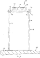
- Fig. 6 shows the channel element 01, the stator element 14 and the cover 21 in arrangement on the bare ceiling 22 of an underground car park in a lateral view.
- Fig. 7 shows the channel element 01, the stator element 14 and the cover 21 after the casting with concrete 23 to form a road surface 24 in cross section. It can be seen that the upper ends 06, 07 and 08 of the support webs 05 and the side walls 03 and 04 lie exactly at the level of the road surface 24 formed by the concrete mass 23 and thus can be run over easily by vehicle wheels. Through the cover 21, the penetration of liquid concrete mass 23, while smoothing the road surface 24, easily avoided. On the underside of the cover 21 clamping elements 25 are provided with which the cover 21 can be fixed on the channel element 01. Clamping elements 25 are realized by cutting and bending down the sheet material from which the cover 21 is made.
- Fig. 8 shows the final state after installation of the gutter element 01 in the concrete poured road surface 24.
- the sub-channels 09 are open at the top and can smoothly dissipate the incident on the road surface 24 surface water sideways and thus drain the road surface 24 in the desired manner ,
Landscapes
- Engineering & Computer Science (AREA)
- Health & Medical Sciences (AREA)
- Life Sciences & Earth Sciences (AREA)
- Hydrology & Water Resources (AREA)
- Public Health (AREA)
- Water Supply & Treatment (AREA)
- Architecture (AREA)
- Civil Engineering (AREA)
- Structural Engineering (AREA)
- Road Paving Structures (AREA)
- Sewage (AREA)
Applications Claiming Priority (1)
| Application Number | Priority Date | Filing Date | Title |
|---|---|---|---|
| DE202017101169.0U DE202017101169U1 (de) | 2017-03-02 | 2017-03-02 | Rinnenelement zur Bildung einer Entwässerungsrinne |
Publications (2)
| Publication Number | Publication Date |
|---|---|
| EP3369862A1 true EP3369862A1 (fr) | 2018-09-05 |
| EP3369862B1 EP3369862B1 (fr) | 2020-04-15 |
Family
ID=58722152
Family Applications (1)
| Application Number | Title | Priority Date | Filing Date |
|---|---|---|---|
| EP18158028.3A Active EP3369862B1 (fr) | 2017-03-02 | 2018-02-22 | Élément de chéneau destiné à former un canal d'écoulement des eaux |
Country Status (2)
| Country | Link |
|---|---|
| EP (1) | EP3369862B1 (fr) |
| DE (1) | DE202017101169U1 (fr) |
Families Citing this family (1)
| Publication number | Priority date | Publication date | Assignee | Title |
|---|---|---|---|---|
| DE102023108011A1 (de) * | 2023-03-29 | 2024-10-02 | Friedrich Wolfarth Gmbh & Co. Kg | Befestigungsvorrichtung für ein Rinnenelement |
Citations (7)
| Publication number | Priority date | Publication date | Assignee | Title |
|---|---|---|---|---|
| DE8220949U1 (de) | 1982-07-22 | 1982-10-28 | M.Meisinger KG, 8890 Aichach | Rinnenelement fuer eine entwaesserungsrinne |
| US4993877A (en) * | 1987-10-02 | 1991-02-19 | Construction Casting Company | Method and apparatus for forming a trench |
| DE29700391U1 (de) * | 1997-01-13 | 1998-05-07 | HYDROTEC Entwässerungstechnik GmbH & Co. KG, 27793 Wildeshausen | Entwässerungsrinne |
| EP1502998A2 (fr) * | 2003-07-31 | 2005-02-02 | MEA Meisinger AG | Elément de drainage et application d'un élément de drainage |
| DE202009016877U1 (de) * | 2009-12-15 | 2010-03-11 | Hydrotec Technologies Ag | Entwässerungsrinnenelement |
| EP2803766A1 (fr) * | 2013-05-14 | 2014-11-19 | REDI S.p.A. | Système de drainage pour surfaces de route |
| DE202016105078U1 (de) * | 2016-09-13 | 2016-10-27 | Graspointner Holding Gmbh | Entwässerungselement und Baukastensystem |
-
2017
- 2017-03-02 DE DE202017101169.0U patent/DE202017101169U1/de active Active
-
2018
- 2018-02-22 EP EP18158028.3A patent/EP3369862B1/fr active Active
Patent Citations (7)
| Publication number | Priority date | Publication date | Assignee | Title |
|---|---|---|---|---|
| DE8220949U1 (de) | 1982-07-22 | 1982-10-28 | M.Meisinger KG, 8890 Aichach | Rinnenelement fuer eine entwaesserungsrinne |
| US4993877A (en) * | 1987-10-02 | 1991-02-19 | Construction Casting Company | Method and apparatus for forming a trench |
| DE29700391U1 (de) * | 1997-01-13 | 1998-05-07 | HYDROTEC Entwässerungstechnik GmbH & Co. KG, 27793 Wildeshausen | Entwässerungsrinne |
| EP1502998A2 (fr) * | 2003-07-31 | 2005-02-02 | MEA Meisinger AG | Elément de drainage et application d'un élément de drainage |
| DE202009016877U1 (de) * | 2009-12-15 | 2010-03-11 | Hydrotec Technologies Ag | Entwässerungsrinnenelement |
| EP2803766A1 (fr) * | 2013-05-14 | 2014-11-19 | REDI S.p.A. | Système de drainage pour surfaces de route |
| DE202016105078U1 (de) * | 2016-09-13 | 2016-10-27 | Graspointner Holding Gmbh | Entwässerungselement und Baukastensystem |
Also Published As
| Publication number | Publication date |
|---|---|
| DE202017101169U1 (de) | 2017-05-02 |
| EP3369862B1 (fr) | 2020-04-15 |
Similar Documents
| Publication | Publication Date | Title |
|---|---|---|
| EP2851477B1 (fr) | Caniveau d'écoulement des eaux | |
| DE60317611T2 (de) | Breite Entwässerungsrinne | |
| DE102008049966B3 (de) | Anschluss für eine Verkehrsleitwand | |
| DE202012010850U1 (de) | Verbundanker zur Bildung einer Betonplatteneinheit sowie mit diesem Verbundanker ausgestattete Betonplatteneinheit | |
| EP3369862B1 (fr) | Élément de chéneau destiné à former un canal d'écoulement des eaux | |
| DE69512411T2 (de) | Flüssigkeitsrohr | |
| EP4438828A1 (fr) | Dispositif de fixation pour un élément de gouttière | |
| EP2188459B1 (fr) | Rigole d'écoulement des eaux | |
| DE60111447T2 (de) | Überlaufsystem mit Überlaufschwelle, insbesondere für vorgefertigte, in den Boden zu versenkende Schwimmbecken und Verfahren zur dessen Konstruktion | |
| EP2158368A2 (fr) | Dispositifs de coffrage et procédé de fabrication de structures monolithiques en béton coulé | |
| AT520609B1 (de) | Entwässerungsvorrichtung zum Entwässern eines Untergrunds | |
| EP1857592A1 (fr) | Procédée de faire un caniveau à fente et un caniveau à fente | |
| EP1736605B1 (fr) | Chassis de balcon, balcon et procédé de réalisation d'un balcon préfabriqué | |
| EP1606466B1 (fr) | Procede de production d'un balcon ou d'une terrasse, piece prefabriquee en beton, et systeme de piece prefabriquee en beton | |
| DE4028148C2 (fr) | ||
| DE202006020230U1 (de) | Entwässerungseinrichtung zum Ableiten von Flüssigkeiten von Verkehrsflächen im Straßenbau | |
| DE3240331C2 (de) | Gesimskappe für Brücken oder dergleichen | |
| DE202011104877U1 (de) | Entwässerungs-Rinnensystem | |
| DE2263371A1 (de) | Vorrichtung zur befestigung eines betonfertigteils | |
| DE202017105401U1 (de) | Gleisfertigteil und Gleiskörper mit wenigstens einem Gleisfertigteil | |
| AT516514B1 (de) | Vorrichtung zur Hangabstützung | |
| DE202024102323U1 (de) | Randabschlusselement für einen Brückenüberbau sowie Brückenüberbau mit Randabschlusselement | |
| DE102015110887A1 (de) | Vorrichtung und Verfahren zum Anheben einer Schachtabdeckung insbesondere Kanaldeckel | |
| EP3992397A1 (fr) | Rail de guidage pour élément d'un recouvrement de piscine et recouvrement de piscine | |
| DE202019100754U1 (de) | Rinnenelement zur Bildung einer Entwässerungsrinne |
Legal Events
| Date | Code | Title | Description |
|---|---|---|---|
| PUAI | Public reference made under article 153(3) epc to a published international application that has entered the european phase |
Free format text: ORIGINAL CODE: 0009012 |
|
| STAA | Information on the status of an ep patent application or granted ep patent |
Free format text: STATUS: THE APPLICATION HAS BEEN PUBLISHED |
|
| AK | Designated contracting states |
Kind code of ref document: A1 Designated state(s): AL AT BE BG CH CY CZ DE DK EE ES FI FR GB GR HR HU IE IS IT LI LT LU LV MC MK MT NL NO PL PT RO RS SE SI SK SM TR |
|
| AX | Request for extension of the european patent |
Extension state: BA ME |
|
| STAA | Information on the status of an ep patent application or granted ep patent |
Free format text: STATUS: REQUEST FOR EXAMINATION WAS MADE |
|
| 17P | Request for examination filed |
Effective date: 20181123 |
|
| RBV | Designated contracting states (corrected) |
Designated state(s): AL AT BE BG CH CY CZ DE DK EE ES FI FR GB GR HR HU IE IS IT LI LT LU LV MC MK MT NL NO PL PT RO RS SE SI SK SM TR |
|
| RIN1 | Information on inventor provided before grant (corrected) |
Inventor name: WOLFARTH, ULRICH |
|
| RIN1 | Information on inventor provided before grant (corrected) |
Inventor name: WOLFARTH, ULRICH |
|
| GRAP | Despatch of communication of intention to grant a patent |
Free format text: ORIGINAL CODE: EPIDOSNIGR1 |
|
| STAA | Information on the status of an ep patent application or granted ep patent |
Free format text: STATUS: GRANT OF PATENT IS INTENDED |
|
| INTG | Intention to grant announced |
Effective date: 20191206 |
|
| GRAS | Grant fee paid |
Free format text: ORIGINAL CODE: EPIDOSNIGR3 |
|
| GRAA | (expected) grant |
Free format text: ORIGINAL CODE: 0009210 |
|
| STAA | Information on the status of an ep patent application or granted ep patent |
Free format text: STATUS: THE PATENT HAS BEEN GRANTED |
|
| AK | Designated contracting states |
Kind code of ref document: B1 Designated state(s): AL AT BE BG CH CY CZ DE DK EE ES FI FR GB GR HR HU IE IS IT LI LT LU LV MC MK MT NL NO PL PT RO RS SE SI SK SM TR |
|
| REG | Reference to a national code |
Ref country code: CH Ref legal event code: EP |
|
| REG | Reference to a national code |
Ref country code: DE Ref legal event code: R096 Ref document number: 502018001171 Country of ref document: DE |
|
| REG | Reference to a national code |
Ref country code: IE Ref legal event code: FG4D Free format text: LANGUAGE OF EP DOCUMENT: GERMAN |
|
| REG | Reference to a national code |
Ref country code: AT Ref legal event code: REF Ref document number: 1257420 Country of ref document: AT Kind code of ref document: T Effective date: 20200515 |
|
| REG | Reference to a national code |
Ref country code: CH Ref legal event code: NV Representative=s name: BODENSEEPATENT PATENTANWAELTE BEHRMANN WAGNER , CH |
|
| REG | Reference to a national code |
Ref country code: NL Ref legal event code: MP Effective date: 20200415 |
|
| REG | Reference to a national code |
Ref country code: LT Ref legal event code: MG4D |
|
| PG25 | Lapsed in a contracting state [announced via postgrant information from national office to epo] |
Ref country code: FI Free format text: LAPSE BECAUSE OF FAILURE TO SUBMIT A TRANSLATION OF THE DESCRIPTION OR TO PAY THE FEE WITHIN THE PRESCRIBED TIME-LIMIT Effective date: 20200415 Ref country code: NO Free format text: LAPSE BECAUSE OF FAILURE TO SUBMIT A TRANSLATION OF THE DESCRIPTION OR TO PAY THE FEE WITHIN THE PRESCRIBED TIME-LIMIT Effective date: 20200715 Ref country code: SE Free format text: LAPSE BECAUSE OF FAILURE TO SUBMIT A TRANSLATION OF THE DESCRIPTION OR TO PAY THE FEE WITHIN THE PRESCRIBED TIME-LIMIT Effective date: 20200415 Ref country code: NL Free format text: LAPSE BECAUSE OF FAILURE TO SUBMIT A TRANSLATION OF THE DESCRIPTION OR TO PAY THE FEE WITHIN THE PRESCRIBED TIME-LIMIT Effective date: 20200415 Ref country code: LT Free format text: LAPSE BECAUSE OF FAILURE TO SUBMIT A TRANSLATION OF THE DESCRIPTION OR TO PAY THE FEE WITHIN THE PRESCRIBED TIME-LIMIT Effective date: 20200415 Ref country code: PT Free format text: LAPSE BECAUSE OF FAILURE TO SUBMIT A TRANSLATION OF THE DESCRIPTION OR TO PAY THE FEE WITHIN THE PRESCRIBED TIME-LIMIT Effective date: 20200817 Ref country code: GR Free format text: LAPSE BECAUSE OF FAILURE TO SUBMIT A TRANSLATION OF THE DESCRIPTION OR TO PAY THE FEE WITHIN THE PRESCRIBED TIME-LIMIT Effective date: 20200716 Ref country code: IS Free format text: LAPSE BECAUSE OF FAILURE TO SUBMIT A TRANSLATION OF THE DESCRIPTION OR TO PAY THE FEE WITHIN THE PRESCRIBED TIME-LIMIT Effective date: 20200815 |
|
| PG25 | Lapsed in a contracting state [announced via postgrant information from national office to epo] |
Ref country code: RS Free format text: LAPSE BECAUSE OF FAILURE TO SUBMIT A TRANSLATION OF THE DESCRIPTION OR TO PAY THE FEE WITHIN THE PRESCRIBED TIME-LIMIT Effective date: 20200415 Ref country code: LV Free format text: LAPSE BECAUSE OF FAILURE TO SUBMIT A TRANSLATION OF THE DESCRIPTION OR TO PAY THE FEE WITHIN THE PRESCRIBED TIME-LIMIT Effective date: 20200415 Ref country code: HR Free format text: LAPSE BECAUSE OF FAILURE TO SUBMIT A TRANSLATION OF THE DESCRIPTION OR TO PAY THE FEE WITHIN THE PRESCRIBED TIME-LIMIT Effective date: 20200415 Ref country code: BG Free format text: LAPSE BECAUSE OF FAILURE TO SUBMIT A TRANSLATION OF THE DESCRIPTION OR TO PAY THE FEE WITHIN THE PRESCRIBED TIME-LIMIT Effective date: 20200715 |
|
| PG25 | Lapsed in a contracting state [announced via postgrant information from national office to epo] |
Ref country code: AL Free format text: LAPSE BECAUSE OF FAILURE TO SUBMIT A TRANSLATION OF THE DESCRIPTION OR TO PAY THE FEE WITHIN THE PRESCRIBED TIME-LIMIT Effective date: 20200415 |
|
| REG | Reference to a national code |
Ref country code: DE Ref legal event code: R097 Ref document number: 502018001171 Country of ref document: DE |
|
| PG25 | Lapsed in a contracting state [announced via postgrant information from national office to epo] |
Ref country code: DK Free format text: LAPSE BECAUSE OF FAILURE TO SUBMIT A TRANSLATION OF THE DESCRIPTION OR TO PAY THE FEE WITHIN THE PRESCRIBED TIME-LIMIT Effective date: 20200415 Ref country code: EE Free format text: LAPSE BECAUSE OF FAILURE TO SUBMIT A TRANSLATION OF THE DESCRIPTION OR TO PAY THE FEE WITHIN THE PRESCRIBED TIME-LIMIT Effective date: 20200415 Ref country code: SM Free format text: LAPSE BECAUSE OF FAILURE TO SUBMIT A TRANSLATION OF THE DESCRIPTION OR TO PAY THE FEE WITHIN THE PRESCRIBED TIME-LIMIT Effective date: 20200415 Ref country code: CZ Free format text: LAPSE BECAUSE OF FAILURE TO SUBMIT A TRANSLATION OF THE DESCRIPTION OR TO PAY THE FEE WITHIN THE PRESCRIBED TIME-LIMIT Effective date: 20200415 Ref country code: RO Free format text: LAPSE BECAUSE OF FAILURE TO SUBMIT A TRANSLATION OF THE DESCRIPTION OR TO PAY THE FEE WITHIN THE PRESCRIBED TIME-LIMIT Effective date: 20200415 Ref country code: IT Free format text: LAPSE BECAUSE OF FAILURE TO SUBMIT A TRANSLATION OF THE DESCRIPTION OR TO PAY THE FEE WITHIN THE PRESCRIBED TIME-LIMIT Effective date: 20200415 Ref country code: ES Free format text: LAPSE BECAUSE OF FAILURE TO SUBMIT A TRANSLATION OF THE DESCRIPTION OR TO PAY THE FEE WITHIN THE PRESCRIBED TIME-LIMIT Effective date: 20200415 |
|
| PLBE | No opposition filed within time limit |
Free format text: ORIGINAL CODE: 0009261 |
|
| STAA | Information on the status of an ep patent application or granted ep patent |
Free format text: STATUS: NO OPPOSITION FILED WITHIN TIME LIMIT |
|
| PG25 | Lapsed in a contracting state [announced via postgrant information from national office to epo] |
Ref country code: PL Free format text: LAPSE BECAUSE OF FAILURE TO SUBMIT A TRANSLATION OF THE DESCRIPTION OR TO PAY THE FEE WITHIN THE PRESCRIBED TIME-LIMIT Effective date: 20200415 Ref country code: SK Free format text: LAPSE BECAUSE OF FAILURE TO SUBMIT A TRANSLATION OF THE DESCRIPTION OR TO PAY THE FEE WITHIN THE PRESCRIBED TIME-LIMIT Effective date: 20200415 |
|
| REG | Reference to a national code |
Ref country code: CH Ref legal event code: PFA Owner name: FRIEDRICH WOLFARTH GMBH AND CO. KG, DE Free format text: FORMER OWNER: FRIEDRICH WOLFARTH GMBH AND CO. KG, DE |
|
| 26N | No opposition filed |
Effective date: 20210118 |
|
| PG25 | Lapsed in a contracting state [announced via postgrant information from national office to epo] |
Ref country code: SI Free format text: LAPSE BECAUSE OF FAILURE TO SUBMIT A TRANSLATION OF THE DESCRIPTION OR TO PAY THE FEE WITHIN THE PRESCRIBED TIME-LIMIT Effective date: 20200415 |
|
| PG25 | Lapsed in a contracting state [announced via postgrant information from national office to epo] |
Ref country code: MC Free format text: LAPSE BECAUSE OF FAILURE TO SUBMIT A TRANSLATION OF THE DESCRIPTION OR TO PAY THE FEE WITHIN THE PRESCRIBED TIME-LIMIT Effective date: 20200415 |
|
| REG | Reference to a national code |
Ref country code: BE Ref legal event code: MM Effective date: 20210228 |
|
| PG25 | Lapsed in a contracting state [announced via postgrant information from national office to epo] |
Ref country code: LU Free format text: LAPSE BECAUSE OF NON-PAYMENT OF DUE FEES Effective date: 20210222 |
|
| PG25 | Lapsed in a contracting state [announced via postgrant information from national office to epo] |
Ref country code: FR Free format text: LAPSE BECAUSE OF NON-PAYMENT OF DUE FEES Effective date: 20210228 Ref country code: IE Free format text: LAPSE BECAUSE OF NON-PAYMENT OF DUE FEES Effective date: 20210222 |
|
| PG25 | Lapsed in a contracting state [announced via postgrant information from national office to epo] |
Ref country code: BE Free format text: LAPSE BECAUSE OF NON-PAYMENT OF DUE FEES Effective date: 20210228 |
|
| GBPC | Gb: european patent ceased through non-payment of renewal fee |
Effective date: 20220222 |
|
| PG25 | Lapsed in a contracting state [announced via postgrant information from national office to epo] |
Ref country code: GB Free format text: LAPSE BECAUSE OF NON-PAYMENT OF DUE FEES Effective date: 20220222 |
|
| PG25 | Lapsed in a contracting state [announced via postgrant information from national office to epo] |
Ref country code: CY Free format text: LAPSE BECAUSE OF FAILURE TO SUBMIT A TRANSLATION OF THE DESCRIPTION OR TO PAY THE FEE WITHIN THE PRESCRIBED TIME-LIMIT Effective date: 20200415 |
|
| P01 | Opt-out of the competence of the unified patent court (upc) registered |
Effective date: 20230529 |
|
| PG25 | Lapsed in a contracting state [announced via postgrant information from national office to epo] |
Ref country code: HU Free format text: LAPSE BECAUSE OF FAILURE TO SUBMIT A TRANSLATION OF THE DESCRIPTION OR TO PAY THE FEE WITHIN THE PRESCRIBED TIME-LIMIT; INVALID AB INITIO Effective date: 20180222 |
|
| PG25 | Lapsed in a contracting state [announced via postgrant information from national office to epo] |
Ref country code: MK Free format text: LAPSE BECAUSE OF FAILURE TO SUBMIT A TRANSLATION OF THE DESCRIPTION OR TO PAY THE FEE WITHIN THE PRESCRIBED TIME-LIMIT Effective date: 20200415 |
|
| PG25 | Lapsed in a contracting state [announced via postgrant information from national office to epo] |
Ref country code: MT Free format text: LAPSE BECAUSE OF FAILURE TO SUBMIT A TRANSLATION OF THE DESCRIPTION OR TO PAY THE FEE WITHIN THE PRESCRIBED TIME-LIMIT Effective date: 20200415 |
|
| PGFP | Annual fee paid to national office [announced via postgrant information from national office to epo] |
Ref country code: DE Payment date: 20250423 Year of fee payment: 8 |
|
| PG25 | Lapsed in a contracting state [announced via postgrant information from national office to epo] |
Ref country code: TR Free format text: LAPSE BECAUSE OF FAILURE TO SUBMIT A TRANSLATION OF THE DESCRIPTION OR TO PAY THE FEE WITHIN THE PRESCRIBED TIME-LIMIT Effective date: 20200415 |
|
| REG | Reference to a national code |
Ref country code: CH Ref legal event code: U11 Free format text: ST27 STATUS EVENT CODE: U-0-0-U10-U11 (AS PROVIDED BY THE NATIONAL OFFICE) Effective date: 20260301 |
|
| PGFP | Annual fee paid to national office [announced via postgrant information from national office to epo] |
Ref country code: AT Payment date: 20260216 Year of fee payment: 9 |
|
| PGFP | Annual fee paid to national office [announced via postgrant information from national office to epo] |
Ref country code: CH Payment date: 20260301 Year of fee payment: 9 |