EP3369873A1 - Système de fixation réversible pour panneaux - Google Patents
Système de fixation réversible pour panneaux Download PDFInfo
- Publication number
- EP3369873A1 EP3369873A1 EP18159731.1A EP18159731A EP3369873A1 EP 3369873 A1 EP3369873 A1 EP 3369873A1 EP 18159731 A EP18159731 A EP 18159731A EP 3369873 A1 EP3369873 A1 EP 3369873A1
- Authority
- EP
- European Patent Office
- Prior art keywords
- longitudinal
- male
- paneling
- face
- external
- Prior art date
- Legal status (The legal status is an assumption and is not a legal conclusion. Google has not performed a legal analysis and makes no representation as to the accuracy of the status listed.)
- Withdrawn
Links
Images



Classifications
-
- E—FIXED CONSTRUCTIONS
- E04—BUILDING
- E04F—FINISHING WORK ON BUILDINGS, e.g. STAIRS, FLOORS
- E04F13/00—Coverings or linings, e.g. for walls or ceilings
- E04F13/07—Coverings or linings, e.g. for walls or ceilings composed of covering or lining elements; Sub-structures therefor; Fastening means therefor
- E04F13/08—Coverings or linings, e.g. for walls or ceilings composed of covering or lining elements; Sub-structures therefor; Fastening means therefor composed of a plurality of similar covering or lining elements
- E04F13/0801—Separate fastening elements
- E04F13/0803—Separate fastening elements with load-supporting elongated furring elements between wall and covering elements
- E04F13/081—Separate fastening elements with load-supporting elongated furring elements between wall and covering elements with additional fastening elements between furring elements and covering elements
- E04F13/0816—Separate fastening elements with load-supporting elongated furring elements between wall and covering elements with additional fastening elements between furring elements and covering elements the additional fastening elements extending into the back side of the covering elements
- E04F13/0819—Separate fastening elements with load-supporting elongated furring elements between wall and covering elements with additional fastening elements between furring elements and covering elements the additional fastening elements extending into the back side of the covering elements inserted into grooves in the back side of the covering elements
-
- E—FIXED CONSTRUCTIONS
- E04—BUILDING
- E04F—FINISHING WORK ON BUILDINGS, e.g. STAIRS, FLOORS
- E04F13/00—Coverings or linings, e.g. for walls or ceilings
- E04F13/07—Coverings or linings, e.g. for walls or ceilings composed of covering or lining elements; Sub-structures therefor; Fastening means therefor
- E04F13/08—Coverings or linings, e.g. for walls or ceilings composed of covering or lining elements; Sub-structures therefor; Fastening means therefor composed of a plurality of similar covering or lining elements
- E04F13/0801—Separate fastening elements
- E04F13/0832—Separate fastening elements without load-supporting elongated furring elements between wall and covering elements
- E04F13/0833—Separate fastening elements without load-supporting elongated furring elements between wall and covering elements not adjustable
- E04F13/0835—Separate fastening elements without load-supporting elongated furring elements between wall and covering elements not adjustable the fastening elements extending into the back side of the covering elements
-
- E—FIXED CONSTRUCTIONS
- E06—DOORS, WINDOWS, SHUTTERS, OR ROLLER BLINDS IN GENERAL; LADDERS
- E06B—FIXED OR MOVABLE CLOSURES FOR OPENINGS IN BUILDINGS, VEHICLES, FENCES OR LIKE ENCLOSURES IN GENERAL, e.g. DOORS, WINDOWS, BLINDS, GATES
- E06B3/00—Window sashes, door leaves, or like elements for closing wall or like openings; Layout of fixed or moving closures, e.g. windows in wall or like openings; Features of rigidly-mounted outer frames relating to the mounting of wing frames
- E06B3/70—Door leaves
- E06B2003/7011—Door leaves with easily replaceable or interchangeable panels
-
- E—FIXED CONSTRUCTIONS
- E06—DOORS, WINDOWS, SHUTTERS, OR ROLLER BLINDS IN GENERAL; LADDERS
- E06B—FIXED OR MOVABLE CLOSURES FOR OPENINGS IN BUILDINGS, VEHICLES, FENCES OR LIKE ENCLOSURES IN GENERAL, e.g. DOORS, WINDOWS, BLINDS, GATES
- E06B3/00—Window sashes, door leaves, or like elements for closing wall or like openings; Layout of fixed or moving closures, e.g. windows in wall or like openings; Features of rigidly-mounted outer frames relating to the mounting of wing frames
- E06B3/30—Coverings, e.g. protecting against weather, for decorative purposes
-
- E—FIXED CONSTRUCTIONS
- E06—DOORS, WINDOWS, SHUTTERS, OR ROLLER BLINDS IN GENERAL; LADDERS
- E06B—FIXED OR MOVABLE CLOSURES FOR OPENINGS IN BUILDINGS, VEHICLES, FENCES OR LIKE ENCLOSURES IN GENERAL, e.g. DOORS, WINDOWS, BLINDS, GATES
- E06B3/00—Window sashes, door leaves, or like elements for closing wall or like openings; Layout of fixed or moving closures, e.g. windows in wall or like openings; Features of rigidly-mounted outer frames relating to the mounting of wing frames
- E06B3/30—Coverings, e.g. protecting against weather, for decorative purposes
- E06B3/301—Coverings, e.g. protecting against weather, for decorative purposes consisting of prefabricated profiled members or glass
- E06B3/303—Covering metal or plastic frames with wooden profiled members
-
- E—FIXED CONSTRUCTIONS
- E06—DOORS, WINDOWS, SHUTTERS, OR ROLLER BLINDS IN GENERAL; LADDERS
- E06B—FIXED OR MOVABLE CLOSURES FOR OPENINGS IN BUILDINGS, VEHICLES, FENCES OR LIKE ENCLOSURES IN GENERAL, e.g. DOORS, WINDOWS, BLINDS, GATES
- E06B3/00—Window sashes, door leaves, or like elements for closing wall or like openings; Layout of fixed or moving closures, e.g. windows in wall or like openings; Features of rigidly-mounted outer frames relating to the mounting of wing frames
- E06B3/30—Coverings, e.g. protecting against weather, for decorative purposes
- E06B3/301—Coverings, e.g. protecting against weather, for decorative purposes consisting of prefabricated profiled members or glass
- E06B3/305—Covering metal frames with plastic or metal profiled members
-
- E—FIXED CONSTRUCTIONS
- E06—DOORS, WINDOWS, SHUTTERS, OR ROLLER BLINDS IN GENERAL; LADDERS
- E06B—FIXED OR MOVABLE CLOSURES FOR OPENINGS IN BUILDINGS, VEHICLES, FENCES OR LIKE ENCLOSURES IN GENERAL, e.g. DOORS, WINDOWS, BLINDS, GATES
- E06B3/00—Window sashes, door leaves, or like elements for closing wall or like openings; Layout of fixed or moving closures, e.g. windows in wall or like openings; Features of rigidly-mounted outer frames relating to the mounting of wing frames
- E06B3/30—Coverings, e.g. protecting against weather, for decorative purposes
- E06B3/301—Coverings, e.g. protecting against weather, for decorative purposes consisting of prefabricated profiled members or glass
- E06B3/306—Covering plastic frames with metal or plastic profiled members
-
- E—FIXED CONSTRUCTIONS
- E06—DOORS, WINDOWS, SHUTTERS, OR ROLLER BLINDS IN GENERAL; LADDERS
- E06B—FIXED OR MOVABLE CLOSURES FOR OPENINGS IN BUILDINGS, VEHICLES, FENCES OR LIKE ENCLOSURES IN GENERAL, e.g. DOORS, WINDOWS, BLINDS, GATES
- E06B3/00—Window sashes, door leaves, or like elements for closing wall or like openings; Layout of fixed or moving closures, e.g. windows in wall or like openings; Features of rigidly-mounted outer frames relating to the mounting of wing frames
- E06B3/54—Fixing of glass panes or like plates
- E06B3/58—Fixing of glass panes or like plates by means of borders, cleats, or the like
- E06B3/5807—Fixing of glass panes or like plates by means of borders, cleats, or the like not adjustable
- E06B3/5821—Fixing of glass panes or like plates by means of borders, cleats, or the like not adjustable hooked on or in the frame member, fixed by clips or otherwise elastically fixed
- E06B3/5828—Fixing of glass panes or like plates by means of borders, cleats, or the like not adjustable hooked on or in the frame member, fixed by clips or otherwise elastically fixed on or with auxiliary pieces
-
- E—FIXED CONSTRUCTIONS
- E06—DOORS, WINDOWS, SHUTTERS, OR ROLLER BLINDS IN GENERAL; LADDERS
- E06B—FIXED OR MOVABLE CLOSURES FOR OPENINGS IN BUILDINGS, VEHICLES, FENCES OR LIKE ENCLOSURES IN GENERAL, e.g. DOORS, WINDOWS, BLINDS, GATES
- E06B3/00—Window sashes, door leaves, or like elements for closing wall or like openings; Layout of fixed or moving closures, e.g. windows in wall or like openings; Features of rigidly-mounted outer frames relating to the mounting of wing frames
- E06B3/54—Fixing of glass panes or like plates
- E06B3/58—Fixing of glass panes or like plates by means of borders, cleats, or the like
- E06B3/585—Fixing of glass panes or like plates by means of borders, cleats, or the like adjustable, e.g. for accommodating panes of various thickness, or with provisions for altering the clamping force on the pane
- E06B3/5857—Fixing of glass panes or like plates by means of borders, cleats, or the like adjustable, e.g. for accommodating panes of various thickness, or with provisions for altering the clamping force on the pane the fixing being adjustable, e.g. in one of several possible positions
-
- E—FIXED CONSTRUCTIONS
- E06—DOORS, WINDOWS, SHUTTERS, OR ROLLER BLINDS IN GENERAL; LADDERS
- E06B—FIXED OR MOVABLE CLOSURES FOR OPENINGS IN BUILDINGS, VEHICLES, FENCES OR LIKE ENCLOSURES IN GENERAL, e.g. DOORS, WINDOWS, BLINDS, GATES
- E06B3/00—Window sashes, door leaves, or like elements for closing wall or like openings; Layout of fixed or moving closures, e.g. windows in wall or like openings; Features of rigidly-mounted outer frames relating to the mounting of wing frames
- E06B3/70—Door leaves
- E06B3/7001—Coverings therefor; Door leaves imitating traditional raised panel doors, e.g. engraved or embossed surfaces, with trim strips applied to the surfaces
-
- F—MECHANICAL ENGINEERING; LIGHTING; HEATING; WEAPONS; BLASTING
- F16—ENGINEERING ELEMENTS AND UNITS; GENERAL MEASURES FOR PRODUCING AND MAINTAINING EFFECTIVE FUNCTIONING OF MACHINES OR INSTALLATIONS; THERMAL INSULATION IN GENERAL
- F16B—DEVICES FOR FASTENING OR SECURING CONSTRUCTIONAL ELEMENTS OR MACHINE PARTS TOGETHER, e.g. NAILS, BOLTS, CIRCLIPS, CLAMPS, CLIPS OR WEDGES; JOINTS OR JOINTING
- F16B11/00—Connecting constructional elements or machine parts by sticking or pressing them together, e.g. cold pressure welding
- F16B11/006—Connecting constructional elements or machine parts by sticking or pressing them together, e.g. cold pressure welding by gluing
-
- F—MECHANICAL ENGINEERING; LIGHTING; HEATING; WEAPONS; BLASTING
- F16—ENGINEERING ELEMENTS AND UNITS; GENERAL MEASURES FOR PRODUCING AND MAINTAINING EFFECTIVE FUNCTIONING OF MACHINES OR INSTALLATIONS; THERMAL INSULATION IN GENERAL
- F16B—DEVICES FOR FASTENING OR SECURING CONSTRUCTIONAL ELEMENTS OR MACHINE PARTS TOGETHER, e.g. NAILS, BOLTS, CIRCLIPS, CLAMPS, CLIPS OR WEDGES; JOINTS OR JOINTING
- F16B5/00—Joining sheets or plates, e.g. panels, to one another or to strips or bars parallel to them
- F16B5/02—Joining sheets or plates, e.g. panels, to one another or to strips or bars parallel to them by means of fastening members using screw-thread
-
- F—MECHANICAL ENGINEERING; LIGHTING; HEATING; WEAPONS; BLASTING
- F16—ENGINEERING ELEMENTS AND UNITS; GENERAL MEASURES FOR PRODUCING AND MAINTAINING EFFECTIVE FUNCTIONING OF MACHINES OR INSTALLATIONS; THERMAL INSULATION IN GENERAL
- F16B—DEVICES FOR FASTENING OR SECURING CONSTRUCTIONAL ELEMENTS OR MACHINE PARTS TOGETHER, e.g. NAILS, BOLTS, CIRCLIPS, CLAMPS, CLIPS OR WEDGES; JOINTS OR JOINTING
- F16B5/00—Joining sheets or plates, e.g. panels, to one another or to strips or bars parallel to them
- F16B5/04—Joining sheets or plates, e.g. panels, to one another or to strips or bars parallel to them by means of riveting
-
- F—MECHANICAL ENGINEERING; LIGHTING; HEATING; WEAPONS; BLASTING
- F16—ENGINEERING ELEMENTS AND UNITS; GENERAL MEASURES FOR PRODUCING AND MAINTAINING EFFECTIVE FUNCTIONING OF MACHINES OR INSTALLATIONS; THERMAL INSULATION IN GENERAL
- F16B—DEVICES FOR FASTENING OR SECURING CONSTRUCTIONAL ELEMENTS OR MACHINE PARTS TOGETHER, e.g. NAILS, BOLTS, CIRCLIPS, CLAMPS, CLIPS OR WEDGES; JOINTS OR JOINTING
- F16B5/00—Joining sheets or plates, e.g. panels, to one another or to strips or bars parallel to them
- F16B5/06—Joining sheets or plates, e.g. panels, to one another or to strips or bars parallel to them by means of clamps or clips
- F16B5/0607—Joining sheets or plates, e.g. panels, to one another or to strips or bars parallel to them by means of clamps or clips joining sheets or plates to each other
- F16B5/0621—Joining sheets or plates, e.g. panels, to one another or to strips or bars parallel to them by means of clamps or clips joining sheets or plates to each other in parallel relationship
- F16B5/0664—Joining sheets or plates, e.g. panels, to one another or to strips or bars parallel to them by means of clamps or clips joining sheets or plates to each other in parallel relationship at least one of the sheets or plates having integrally formed or integrally connected snap-in-features
Definitions
- the present invention belongs to the sector of the kits used for reversibly mounting decorative, paneling, and/or insulating elements on any kinds of surfaces.
- the present invention concerns a practical system for mounting finishing elements, made from wood or other materials, including fine materials, on supports of different kinds, for instance panels of pieces of furniture, masonry walls, doors and windows, slabs of marble, and panes of glass.
- the present invention refers to a kit for fixing paneling elements for doors and windows of a conventional type, generally made from wood or metal.
- the invention can also operate as a glazing bead.
- a method for applying the kit is also disclosed.
- Such paneling elements are often made from wood or other fine materials. Besides performing a decorative function, such panelings also perform a protection and insulation function for the surface underneath.
- staff beads and jambs generally made from wood or aluminum, is known for paneling the fixed frames of doors and windows.
- Profile elements made from wood or other fine materials are also used to panel frames of the movable parts of doors and window, such as for instance the shutters of a windows.
- doors and windows made from metal or PVC are particularly requested in the market because of thermal and acoustical insulation reasons, which wood panelings are often applied to with the purpose of improving their appearance.
- junction elements such as, for instance, nails or screws
- the "head" of the junction element, once driven into the paneling remains “in sight”, thus spoiling the appearance of the paneling, and additionally in that it is necessary to drill both the paneling and the substrate which this one is to be joined to, thus weakening them.
- paneling systems have been developed for doors and windows wherein a finishing strip connects to the frame by way of snap fasteners, or other embedding means, for instance by way of longitudinal grooves present on the inner side of the paneling and suitable for receiving respective bulges projecting from the frame of the door or window.
- the frame of the door or window be specifically manufactured for making it possible to connect it to the paneling element, and the latter shall also have been specially implemented so as to make it possible to expressly match it to a given frame for doors or windows.
- European patent EP0695847 claims an assembly of profiles made from metal-wood, used for implementing doors and windows, substantially consisting of wood panelings which are associated with the metal profile making up the frame of the door or window, by way of strips made from a plastic material.
- plastic strips connect to the metal profile on one side and to the wood panel on the other side, thanks to the presence of projecting and deformable bulges suitable for embedding in specifically designed seats cut in the metal profile and in the wood paneling respectively.
- a first object of the present invention is thus to provide a practical and cost-effective kit for reversibly mounting decorative and/or insulating paneling elements made from wood or other materials, including fine materials, on surfaces of different kinks such as for instance frames of doors and windows, masonries, walls, and pieces of furniture for interiors.
- an object of the present invention is to provide an innovative system that does not require the use of chemical adhesives on the external paneling portion nor requires to drill it in order to connect it to the surface to be paneled.
- the system according to the present patent application allows to apply decorative and/or insulating elements on any kinds of frames for doors and windows, even if the latter are of a conventional type, hence not formed of profiles specially shaped for being connected to a specifically manufactured paneling element.
- Another undoubted advantage of the present invention is in that it allows to easily dismantle the paneling, for instance in order to perform maintenance operations on a door or window or to replace the paneling in the case of an excessive tear and wear or following a damage.
- the present paneling system can be applied not only onto mobile frames and onto fixed frames of doors and windows, but also, for instance, on panelings of pieces of furniture or on masonries inside or outside a building, and more generally onto any kinds of surfaces.
- Some embodiments of the invention make it possible to secure a glass or a double glazing to the support, possibly by way of a standard gasket, received in seats that develop longitudinally.
- a surface paneling securing kit comprising an external paneling element and a male interconnection element, the latter to be integrally connected to the surface of the internal support which the paneling will be applied onto.
- the male interconnection element is smooth, i.e. with no bulges, in particular it doesn't have any bulges suitable for engaging corresponding seats expressly cut in the internal support; in other words, the male interconnection element (1) features a flat inner longitudinal face.
- connection means between said internal support and the male interconnection element are of a known type, for instance screws, bolts, or rivets can be used; if necessary, glues or double-sided adhesive tapes.
- the external paneling element which comprises an external paneling portion, and the male interconnection element are connected to each other reversibly.
- such external paneling element is a plate-like body or a thin and elongate longitudinal element
- said male interconnection element is an elongate element featuring at least one inner longitudinal face suitable for facing the surface of the support to be paneled and at least one outer longitudinal face featuring one or several longitudinal ribs suitable for reversibly engaging respective longitudinal channels present in the inner surface of said external paneling element.
- such longitudinal ribs feature serrated ends so as to increase the friction with the inner surface of said longitudinal channels of the paneling element and to reduce the risk of their possible slippages or accidental peeling off.
- a longitudinal sealing element is interposed between a longitudinal rib and its respective longitudinal channel, which has a number of serrations on the outer side, so as to prevent the paneling element from accidently detaching.
- the longitudinal sealing element might also provide tightness and/or greater thermal insulation.
- such longitudinal sealing element is made from an at least partially deformable material, at least part of its cross section being shaped like a letter "U" and whose lateral, inner and outer surfaces feature a plurality of male longitudinal ridges, parallel to each other and shaped in such a way that at least one male longitudinal ridge of the inner lateral surfaces engages a respective longitudinal recess of said one or several longitudinal ribs.
- said male longitudinal ridges of the outer lateral surfaces are suitable for getting deformed in order to reversibly engage their corresponding longitudinal channels defined on the inner face of the external paneling element.
- one male interconnection element can include a plurality of longitudinal ribs. If several longitudinal ribs are provided, then it is also possible to connect more external paneling elements.
- the kit possibly comprises a second male interconnection element, which allows to also perform a glazing bead function, as better described below.
- a male longitudinal glazing bead element which is suitable for being made integral with a slotted door or window by taking advantage of the groove generally present in the wood close to the glass.
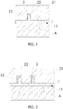
- the reversible paneling fixing kit according to the present invention comprises a male interconnection element (1), which can be reversibly connected to at least one external paneling element (2) which comprises an external paneling portion (21).
- such internal support (A) is for instance a fixed frame or a movable frame of a door or window, or a wall of an interior room of a house or a panel of a piece of furniture or even a pane of glass or a slab of marble.
- said male interconnection element (1) has the shape of an elongate longitudinal body, for instance a metal profile, and features at least one inner longitudinal face (11) suitable for being connected, by way of known means, to the surface of said internal support (A), without any need for the latter to be properly preset; for this purpose, said at least one inner longitudinal face (11) is flat, i.e. no bulges nor other devices depart therefrom for locking into corresponding seats cut in the internal support, and it possibly includes a number of holes for nails, screws, or rivets, or it can be made integral by way of other known connection means, such as for instance snap fasteners or snap-in devices.
- the male interconnection element (1) features at least one outer longitudinal face, from which one or several longitudinal ribs (12) orthogonally project, which reversibly engage inside their respective longitudinal channels (22) present internally to said one or several external paneling elements (2).
- each of said one or several longitudinal ribs (12) include a plurality of parallel longitudinal recesses (13) which form serrations, so that each of said one or several longitudinal ribs (12) is suitable for engaging a corresponding longitudinal sealing element (3).
- the latter is made from a material at least partially deformable, usually synthetic rubber, for instance Ethylene-Propylene Diene Monomer.
- the longitudinal sealing element (3) has at least part of the cross section shaped like a letter "U", whose lateral, inner and outer surfaces, feature a plurality of male longitudinal ridges (31, 32). More specifically, the male longitudinal ridges (31) of the inner lateral surfaces are parallel to each other and are shaped in such a way that at least one ridge engages a respective longitudinal recess (13) of said one or several ribs (12).
- said male longitudinal ridges (32) of the outer lateral surfaces of said longitudinal sealing element (3) are suitable for getting deformed to reversibly engage one of said one or several longitudinal ribs (12) in a corresponding longitudinal channel (22) defined on the inner face of an external paneling element (2).
- Every external paneling element (2) is mounted on a male interconnection element (1) by introducing each of said one or several male longitudinal ridges (32) in a respective longitudinal channel (22) and exerting an appropriate pressure thereon up to having the rib (12) completely inserted into the longitudinal channel (22); in this way, one is sure that an external paneling element (2) cannot accidentally slip off or detach from the male interconnection element (1).
- the parallel longitudinal recesses (13) that form the serrations are shaped in such a way as to offer a greater resistance to the disengagement of the rib from the channel.
- This effect is achieved thanks to the special profile of the serration, as seen, for instance, in figures 7 and 8 .
- the serration thus obtained is of a sawtooth type, the tilted part facing outwards. Because of the longitudinal rib (12) being inserted into the longitudinal channel (22), the longitudinal sealing element (3) gets deformed and compressed in the longitudinal recesses (13); the sawtooth shape makes a subsequently disengagement more difficult.
- the male longitudinal ridges (32) of the outer lateral surfaces of the longitudinal sealing element (3) are also shaped in such a way as to offer a greater resistance to outwards flexure, as with the serrations of the longitudinal ribs.
- Another object of said longitudinal sealing element (3) might also be that of providing tightness between an external paneling element (2) and the male interconnection element (1) and thermally insulating the former from the second.
- the inner longitudinal face (11) of the male interconnection element (1) is connected by way of nails, screws, rivets, glues, or adhesive tapes to the internal support (A), the latter consisting of the frame of a shutter of a door or window.
- the external paneling portion can advantageously be a strip made from wood or another fine material, internally featuring one or several longitudinal channels (22) internally to which respective longitudinal ribs (12) present on said male interconnection element (1) are inserted.
- the fixing system for panelings can be used for implementing more articulated compositions, such as for instance structures for mounting panelings of interior masonries of a building or for connecting a pane of glass to a panel.
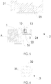
- the external paneling element (2) comprises a female longitudinal interconnection element, the latter featuring an external portion (23) integrally connected to said external paneling portion (21), and an internal portion (24) which defines at least one longitudinal channel (22) which receives a longitudinal rib (12) of the male interconnection element (1).
- the latter possibly comprises a longitudinal rib (12) which features a plurality of parallel longitudinal recesses (13) in a second section perpendicular to a first section projecting from the outer longitudinal face of the same male interconnection element (1).
- a separation element is interposed between said external portion (23), which is preferably flat, and said internal portion (24), which allows to move the external paneling portion (21) away from the internal support (A).
- the side walls of the longitudinal channel (22) consist of a pair of projecting longitudinal ridges (25), parallel to each other, present in the internal portion (24).
- At least the inner faces of the projecting longitudinal ridges feature a plurality of parallel longitudinal recesses (26), which form serrations, so as to offer a greater resistance to accidental slippages.
- a version of the male interconnection element (1) comprises a knurled external portion (14) suitable for being integrally connected to a corresponding knurled internal portion (44) of a un second male interconnection element (4).
- the latter can operate as a glazing bead.
Landscapes
- Engineering & Computer Science (AREA)
- Architecture (AREA)
- Civil Engineering (AREA)
- Structural Engineering (AREA)
- Securing Of Glass Panes Or The Like (AREA)
Applications Claiming Priority (1)
| Application Number | Priority Date | Filing Date | Title |
|---|---|---|---|
| IT202017000024121U IT201700024121U1 (it) | 2017-03-03 | 2017-03-03 | Sistema di fissaggio reversibile per rivestimenti |
Publications (1)
| Publication Number | Publication Date |
|---|---|
| EP3369873A1 true EP3369873A1 (fr) | 2018-09-05 |
Family
ID=61557198
Family Applications (1)
| Application Number | Title | Priority Date | Filing Date |
|---|---|---|---|
| EP18159731.1A Withdrawn EP3369873A1 (fr) | 2017-03-03 | 2018-03-02 | Système de fixation réversible pour panneaux |
Country Status (2)
| Country | Link |
|---|---|
| EP (1) | EP3369873A1 (fr) |
| IT (1) | IT201700024121U1 (fr) |
Cited By (1)
| Publication number | Priority date | Publication date | Assignee | Title |
|---|---|---|---|---|
| CN109653637A (zh) * | 2018-12-14 | 2019-04-19 | 广信铝业股份有限公司 | 一种密封性能好的组合式型材 |
Citations (5)
| Publication number | Priority date | Publication date | Assignee | Title |
|---|---|---|---|---|
| EP0695847A1 (fr) | 1994-08-02 | 1996-02-07 | HYDRO ALUMINIUM SYSTEMS S.p.A. | Ensemble de profilés mixtes métal-bois pour cadres de portes et fenêtres |
| WO1996018018A1 (fr) * | 1994-12-05 | 1996-06-13 | Brügmann Frisoplast Gmbh | Dispositif de fixation |
| EP1203856A1 (fr) * | 2000-11-02 | 2002-05-08 | Michel Grosjean | Couvre-joint |
| CN202380888U (zh) | 2011-08-12 | 2012-08-15 | 韦尚进 | 木铝、木塑、木钢、木塑铝、木铝塑装配式复合门窗型材 |
| US20120204504A1 (en) * | 2008-04-02 | 2012-08-16 | Friedrich Knapp | Fastening device for glass panes |
-
2017
- 2017-03-03 IT IT202017000024121U patent/IT201700024121U1/it unknown
-
2018
- 2018-03-02 EP EP18159731.1A patent/EP3369873A1/fr not_active Withdrawn
Patent Citations (5)
| Publication number | Priority date | Publication date | Assignee | Title |
|---|---|---|---|---|
| EP0695847A1 (fr) | 1994-08-02 | 1996-02-07 | HYDRO ALUMINIUM SYSTEMS S.p.A. | Ensemble de profilés mixtes métal-bois pour cadres de portes et fenêtres |
| WO1996018018A1 (fr) * | 1994-12-05 | 1996-06-13 | Brügmann Frisoplast Gmbh | Dispositif de fixation |
| EP1203856A1 (fr) * | 2000-11-02 | 2002-05-08 | Michel Grosjean | Couvre-joint |
| US20120204504A1 (en) * | 2008-04-02 | 2012-08-16 | Friedrich Knapp | Fastening device for glass panes |
| CN202380888U (zh) | 2011-08-12 | 2012-08-15 | 韦尚进 | 木铝、木塑、木钢、木塑铝、木铝塑装配式复合门窗型材 |
Cited By (2)
| Publication number | Priority date | Publication date | Assignee | Title |
|---|---|---|---|---|
| CN109653637A (zh) * | 2018-12-14 | 2019-04-19 | 广信铝业股份有限公司 | 一种密封性能好的组合式型材 |
| CN109653637B (zh) * | 2018-12-14 | 2020-05-29 | 广信铝业股份有限公司 | 一种密封性能好的组合式型材 |
Also Published As
| Publication number | Publication date |
|---|---|
| IT201700024121U1 (it) | 2018-09-03 |
Similar Documents
| Publication | Publication Date | Title |
|---|---|---|
| CA2907686C (fr) | Ensemble encadrement de fenetre | |
| US3016993A (en) | Building framing unit | |
| US6148584A (en) | Trim attachment system | |
| US20190136549A1 (en) | Stop bead for panel-based siding, and related methods and systems | |
| US10450743B2 (en) | Window and curtain wall mullions, transoms and systems | |
| GB2441217A (en) | Trim assembly | |
| US7340866B1 (en) | Wall adapter | |
| US11066834B2 (en) | Cladding | |
| CA2876829A1 (fr) | Systeme et procede d'installation d'une garniture et systeme de fixation dissimule | |
| US20180355656A1 (en) | Profile for fastening panes | |
| US20250341126A1 (en) | Apparatus and method for installing a closure in a building | |
| EP2395180A2 (fr) | Panneau pour revêtements de sol, mur ou plafond et procédé de fabrication d'un tel panneau | |
| EP3228795A1 (fr) | Ensemble de fenêtre ou de porte en bois pourvu d'un revêtement extérieur | |
| WO2017165911A1 (fr) | Système d'installation de plinthe et de chambranle | |
| EP3369873A1 (fr) | Système de fixation réversible pour panneaux | |
| GB2576349A (en) | Improvements in or relating to sash members | |
| WO2022226609A1 (fr) | Ensemble cadre monobloc universel avec finitions à vue interne et externe et mousse d'étanchéité | |
| US9194137B2 (en) | Trim molding system and method | |
| US20060053734A1 (en) | Hide-a-nail | |
| CA3095454A1 (fr) | Coin prefini et prefabrique destine a etre fixe en une seule etape dans des applications de menuiserie | |
| KR100757342B1 (ko) | 창호프레임용 마감재 | |
| EP4424970A1 (fr) | Procédé de fabrication de joints d'étanchéité et joint d'étanchéité | |
| AU2026200329A1 (en) | An auxiliary framing system | |
| JP3208073U7 (fr) | ||
| JP3208073U (ja) | 複層ガラス据え付け用フレーム |
Legal Events
| Date | Code | Title | Description |
|---|---|---|---|
| PUAI | Public reference made under article 153(3) epc to a published international application that has entered the european phase |
Free format text: ORIGINAL CODE: 0009012 |
|
| STAA | Information on the status of an ep patent application or granted ep patent |
Free format text: STATUS: THE APPLICATION HAS BEEN PUBLISHED |
|
| AK | Designated contracting states |
Kind code of ref document: A1 Designated state(s): AL AT BE BG CH CY CZ DE DK EE ES FI FR GB GR HR HU IE IS IT LI LT LU LV MC MK MT NL NO PL PT RO RS SE SI SK SM TR |
|
| AX | Request for extension of the european patent |
Extension state: BA ME |
|
| STAA | Information on the status of an ep patent application or granted ep patent |
Free format text: STATUS: REQUEST FOR EXAMINATION WAS MADE |
|
| 17P | Request for examination filed |
Effective date: 20190225 |
|
| RBV | Designated contracting states (corrected) |
Designated state(s): AL AT BE BG CH CY CZ DE DK EE ES FI FR GB GR HR HU IE IS IT LI LT LU LV MC MK MT NL NO PL PT RO RS SE SI SK SM TR |
|
| STAA | Information on the status of an ep patent application or granted ep patent |
Free format text: STATUS: EXAMINATION IS IN PROGRESS |
|
| 17Q | First examination report despatched |
Effective date: 20210701 |
|
| STAA | Information on the status of an ep patent application or granted ep patent |
Free format text: STATUS: THE APPLICATION IS DEEMED TO BE WITHDRAWN |
|
| 18D | Application deemed to be withdrawn |
Effective date: 20211112 |