EP3369877B1 - Rahmen umfassend eine rahmenstruktur, ein gewebe und eine vorrichtung zum befestigen des gewebes auf einem profil der rahmenstruktur - Google Patents
Rahmen umfassend eine rahmenstruktur, ein gewebe und eine vorrichtung zum befestigen des gewebes auf einem profil der rahmenstruktur Download PDFInfo
- Publication number
- EP3369877B1 EP3369877B1 EP18159652.9A EP18159652A EP3369877B1 EP 3369877 B1 EP3369877 B1 EP 3369877B1 EP 18159652 A EP18159652 A EP 18159652A EP 3369877 B1 EP3369877 B1 EP 3369877B1
- Authority
- EP
- European Patent Office
- Prior art keywords
- profile
- frame
- fastening
- outer edge
- fixing
- Prior art date
- Legal status (The legal status is an assumption and is not a legal conclusion. Google has not performed a legal analysis and makes no representation as to the accuracy of the status listed.)
- Active
Links
Images

Classifications
-
- E—FIXED CONSTRUCTIONS
- E04—BUILDING
- E04B—GENERAL BUILDING CONSTRUCTIONS; WALLS, e.g. PARTITIONS; ROOFS; FLOORS; CEILINGS; INSULATION OR OTHER PROTECTION OF BUILDINGS
- E04B2/00—Walls, e.g. partitions, for buildings; Wall construction with regard to insulation; Connections specially adapted to walls
- E04B2/74—Removable non-load-bearing partitions; Partitions with a free upper edge
- E04B2/7407—Removable non-load-bearing partitions; Partitions with a free upper edge assembled using frames with infill panels or coverings only; made-up of panels and a support structure incorporating posts
- E04B2/7416—Removable non-load-bearing partitions; Partitions with a free upper edge assembled using frames with infill panels or coverings only; made-up of panels and a support structure incorporating posts with free upper edge, e.g. for use as office space dividers
-
- E—FIXED CONSTRUCTIONS
- E04—BUILDING
- E04B—GENERAL BUILDING CONSTRUCTIONS; WALLS, e.g. PARTITIONS; ROOFS; FLOORS; CEILINGS; INSULATION OR OTHER PROTECTION OF BUILDINGS
- E04B2/00—Walls, e.g. partitions, for buildings; Wall construction with regard to insulation; Connections specially adapted to walls
- E04B2/74—Removable non-load-bearing partitions; Partitions with a free upper edge
- E04B2/7407—Removable non-load-bearing partitions; Partitions with a free upper edge assembled using frames with infill panels or coverings only; made-up of panels and a support structure incorporating posts
-
- E—FIXED CONSTRUCTIONS
- E04—BUILDING
- E04B—GENERAL BUILDING CONSTRUCTIONS; WALLS, e.g. PARTITIONS; ROOFS; FLOORS; CEILINGS; INSULATION OR OTHER PROTECTION OF BUILDINGS
- E04B9/00—Ceilings; Construction of ceilings, e.g. false ceilings; Ceiling construction with regard to insulation
- E04B9/30—Ceilings; Construction of ceilings, e.g. false ceilings; Ceiling construction with regard to insulation characterised by edge details of the ceiling; e.g. securing to an adjacent wall
- E04B9/303—Ceilings; Construction of ceilings, e.g. false ceilings; Ceiling construction with regard to insulation characterised by edge details of the ceiling; e.g. securing to an adjacent wall for flexible tensioned membranes
-
- E—FIXED CONSTRUCTIONS
- E04—BUILDING
- E04F—FINISHING WORK ON BUILDINGS, e.g. STAIRS, FLOORS
- E04F13/00—Coverings or linings, e.g. for walls or ceilings
- E04F13/002—Coverings or linings, e.g. for walls or ceilings made of webs, e.g. of fabrics, or wallpaper, used as coverings or linings
- E04F13/005—Stretched foil- or web-like elements attached with edge gripping devices
-
- E—FIXED CONSTRUCTIONS
- E04—BUILDING
- E04H—BUILDINGS OR LIKE STRUCTURES FOR PARTICULAR PURPOSES; SWIMMING OR SPLASH BATHS OR POOLS; MASTS; FENCING; TENTS OR CANOPIES, IN GENERAL
- E04H1/00—Buildings or groups of buildings for dwelling or office purposes; General layout, e.g. modular co-ordination or staggered storeys
- E04H1/12—Small buildings or other erections for limited occupation, erected in the open air or arranged in buildings, e.g. kiosks, waiting shelters for bus stops or for filling stations, roofs for railway platforms, watchmen's huts or dressing cubicles
- E04H1/1272—Exhibition stands
-
- F—MECHANICAL ENGINEERING; LIGHTING; HEATING; WEAPONS; BLASTING
- F16—ENGINEERING ELEMENTS AND UNITS; GENERAL MEASURES FOR PRODUCING AND MAINTAINING EFFECTIVE FUNCTIONING OF MACHINES OR INSTALLATIONS; THERMAL INSULATION IN GENERAL
- F16B—DEVICES FOR FASTENING OR SECURING CONSTRUCTIONAL ELEMENTS OR MACHINE PARTS TOGETHER, e.g. NAILS, BOLTS, CIRCLIPS, CLAMPS, CLIPS OR WEDGES; JOINTS OR JOINTING
- F16B5/00—Joining sheets or plates, e.g. panels, to one another or to strips or bars parallel to them
- F16B5/06—Joining sheets or plates, e.g. panels, to one another or to strips or bars parallel to them by means of clamps or clips
- F16B5/0692—Joining sheets or plates, e.g. panels, to one another or to strips or bars parallel to them by means of clamps or clips joining flexible sheets to other sheets or plates or to strips or bars
-
- G—PHYSICS
- G09—EDUCATION; CRYPTOGRAPHY; DISPLAY; ADVERTISING; SEALS
- G09F—DISPLAYING; ADVERTISING; SIGNS; LABELS OR NAME-PLATES; SEALS
- G09F15/00—Boards, hoardings, pillars, or like structures for notices, placards, posters, or the like
- G09F15/0006—Boards, hoardings, pillars, or like structures for notices, placards, posters, or the like planar structures comprising one or more panels
- G09F15/0025—Boards, hoardings, pillars, or like structures for notices, placards, posters, or the like planar structures comprising one or more panels display surface tensioning means
-
- G—PHYSICS
- G09—EDUCATION; CRYPTOGRAPHY; DISPLAY; ADVERTISING; SEALS
- G09F—DISPLAYING; ADVERTISING; SIGNS; LABELS OR NAME-PLATES; SEALS
- G09F19/00—Advertising or display means not otherwise provided for
- G09F19/22—Advertising or display means on roads, walls or similar surfaces, e.g. illuminated
- G09F19/226—External wall display means; Facade advertising means
-
- E—FIXED CONSTRUCTIONS
- E04—BUILDING
- E04B—GENERAL BUILDING CONSTRUCTIONS; WALLS, e.g. PARTITIONS; ROOFS; FLOORS; CEILINGS; INSULATION OR OTHER PROTECTION OF BUILDINGS
- E04B2/00—Walls, e.g. partitions, for buildings; Wall construction with regard to insulation; Connections specially adapted to walls
- E04B2/74—Removable non-load-bearing partitions; Partitions with a free upper edge
- E04B2002/7479—Details of connection of flexible sheets to frame or posts
Definitions
- the present invention relates to a device for fixing a canvas on a profile. It also relates to a canvas provided with such a fixing device, a profile intended to receive such a fixing device, a frame structure formed by such profiles, a frame comprising such a frame structure, and an installation formed by such frames fixed together, or on a frame (wall, chassis, structure)
- the field of the invention is the field of devices for fixing a canvas to a frame structure, in particular, but in no way limiting, for the production of an exhibition stand, a reception stand, a display panel, an advertising panel, a decorative panel or frame, etc.
- Each frame structure is designed to receive a flexible canvas, fixed to said structure using a fixing device, in a removable or detachable manner.
- a canvas is fixed to a frame structure using flexible strips called fixing joints, previously sewn or welded onto the canvas, and which fit into a groove provided on the frame structure.
- Such an uncovered space causes a degraded visual rendering, especially when several frames are assembled together or edge to edge on a frame to form a single overall frame.
- the space not covered by the canvas at the edges of the frame constitutes wasted space which reduces the usable space of a frame, which can be a disadvantage, especially when the number of frames increases.
- An aim of the present invention is to remedy the aforementioned drawbacks.
- Another aim of the invention is to provide a frame of simple, compact and rigid construction and allowing easy assembly.
- the invention proposes to achieve at least one of the aforementioned aims by a frame according to claim 1.
- the covering portion of the fixing device is curved relative to the fixing portion of said fixing device, towards the outer edge of the profile, i.e. in an opposite direction to the direction in which the fabric extends.
- the covering portion of the fixing device is curved relative to the fixing portion of the fixing device, in a direction perpendicular to the profile, going from the inner edge to the outer edge.
- the fixing device allows the canvas to occupy a larger area in the width direction of the profile, which increases the useful area in a frame formed by such a profile. Furthermore, by adjusting the width of the covering part, it is even possible to exploit the entire width of the profile, which makes it possible to exploit the entire surface of a frame delimited by the outer edges of the frame and beyond.
- the fixing device also makes it possible to improve the visual rendering obtained with a frame or several frames fixed together edge to edge in limiting, or even eliminating, the spaces not covered by the canvas at the junction between two frames.
- the first fixing part of the fixing device may be provided to achieve a removable or detachable fixing, by engagement, and in particular by male-female engagement.
- the first fixing part of the fixing device can be formed by a male shape intended to fit into an opening provided on the profile.
- the first fixing part of the fixing device can be formed by a tab intended to be inserted into a groove provided on a front face of said profile.
- the first fixing part of the fixing device can be formed by an opening provided to accommodate a male shape, such as a tab, provided on the profile.
- the first fixing part of the fixing device can provide a removable or detachable fixing, by clipping, by gluing, by mechanical tightening, etc.
- the covering part of the fixing device may have a width such that it extends from said fixing part at least to the outer edge of the profile, in the direction going from the inner edge to the outer edge.
- the covering part covers the entire frame up to the outer edge, which allows the canvas to occupy the entire frame formed by the profile.
- the covering portion of the fixing device may have a width such that it extends from said fixing portion beyond from the outer edge of the profile, in the direction from the inner edge to the outer edge.
- the covering portion extends beyond the outer edge of the profile so that it can compress against a fastening device of an adjacent profile or frame to provide a continuous connection, without any space between the two adjacent frames.
- the distal end of the covering part of the fixing device can have a smaller thickness compared to the rest of the covering part, which facilitates its compression or deformation when it comes to be crushed by compression on a fixing device of an adjacent profile, or frame.
- the upper surface of the covering portion of the fixing device may comprise a distal portion extending towards the profile.
- the distal portion, or distal end of the covering portion corresponds to that located opposite the fixing portion.
- the upper surface of the covering part corresponds to that on the canvas side, opposite to that on the profile side.
- the covering part is compressed onto a fixing device of an adjacent profile or frame and naturally sinks towards the two adjacent profiles or frames so that it does not protrude towards the canvas. This makes it possible to obtain a non-overhanging junction and a continuous surface when associating two frames side by side.
- the distal end of the covering part of the fixing device can be beveled by at least one oblique cut, for example at an angle of 45°, starting from the upper surface and returning towards the profile.
- the first cut can be made over a greater distance compared to the second cut.
- Each of the cuts can have an angle of 45°, for example
- the fixing device may further comprise a second fixing part, for fixing the canvas to said device.
- the second fixing part may be formed by a surface of the fixing device to which the canvas is fixed prior to assembly with the profile.
- the canvas can be attached to the fixing surface by sewing, gluing, welding, stapling, etc.
- the second fixing part of the fixing device may be formed by a surface of the first fixing part.
- the surface of the first fixing part serving as the surface for fixing the canvas to the fixing device may be on the side of the covering part, or on the outer edge of the profile.
- the surface of the first fixing part serving as a surface for fixing the canvas to the fixing device may be a surface, which in use, is engaged with a fixing means provided on the profile, such as a groove provided to receive the first fixing part, which makes it possible to make the fixing of the canvas more robust.
- the second fixing part of the fixing device is chosen so that, when the canvas is fixed to said second fixing part, said canvas covers the covering part of said fixing device.
- the second fixing part of the fixing device may be formed by a surface of the covering part.
- the fixing device is in the form of a " ⁇ " (an inverted “ L ”) or a " T " whose vertical branch forms the fixing part and the horizontal branch forms the covering part.
- the fixing device can be made of a rigid material, such as hard plastic, or metal or even aluminum.
- the fixing device can be made of a flexible material, for example made of silicone, thermoplastic elastomer (TPE), PVC.
- TPE thermoplastic elastomer
- the fixing device may, preferably, be in the form of a flexible joint.
- the fixing device may be made by casting or extrusion, or by any other known technique.
- the canvas may be provided with a fixing device on at least part of its periphery.
- the canvas may be provided with fixing devices around its entire periphery, continuously or discontinuously.
- the fixing device can be fixed on the canvas by sewing, gluing, welding, stapling, molding, etc.
- the profile comprises a groove, formed between an inner edge and an outer edge, and intended to receive the first fixing part of said device, said profile having between its outer edge and the groove a thickness less than its thickness between its inner edge and the groove.
- Such a difference in thickness makes it possible to compensate for the excess thickness formed by the overlapping part between the groove and the outer edge, so as to obtain a flat surface when the canvas is fixed to the profile.
- the difference in thickness may correspond to, or be greater than, the thickness of the covering part, possibly increased by the thickness of the canvas.
- the profile can be made of a rigid material, such as hard plastic, aluminum, metal, wood, composite material etc.
- the frame structure intended to receive the canvas, includes at least one profile.
- the frame structure When the frame structure is rectangular, it may comprise two profiles forming two opposite sides of the frame structure, and preferably four profiles each forming one side of said structure.
- the frame structure can be formed by a profile on each of these sides.
- the frames may be fixed together at the ends, for example by screwing or bolting, or by any other positioning and holding device, or affixed and linked to a frame.
- FIGURE 1 is a partial schematic representation, according to a sectional view, of a non-limiting exemplary embodiment of a frame.
- Frame 100 shown in the FIGURE 1 , comprises a fixing device 102 used to fix a canvas T on a profile 104, forming one side of a frame for example.
- the profile 104 has an inner edge 104 1 located on the side of the canvas T and an outer edge 104 2 located on the side opposite the canvas T.
- the canvas T extends on the side of the inner edge 104 1 of the profile 104.
- the profile 104 comprises a groove 104 3 for fixing the fixing device 102 to the profile 104, for example by clamping, bracing, pinching, etc.
- the fixing device 102 comprises a fixing portion 106 which fits into the groove 104 3 .
- the groove 104 3 or the fixing portion 106, may be notched to help maintain the fixing portion 106 in the groove 104 3 .
- the fixing device 102 further comprises a covering portion 108, forming an overhang, and extending from the groove 104 3 towards the outer edge 104 2 of the profile and covering a part, or the whole of the profile, between the groove 104 3 and the outer edge 104 2 of the profile.
- the width of the covering portion 108 is adjusted so that the distal end 110 of the covering portion 108 is aligned with the outer edge 104 2 of the profile 104.
- the covering portion 108 extends beyond the fixing portion 106 in the direction 112 going from the inner edge 104 1 of the profile 104 towards the outer edge 104 2 of the profile 104.
- the covering portion 108 is itself covered by the fabric T, up to the distal end 110 of the covering portion 108.
- the canvas T is fixed to the upper surface 114 of said covering part 108 for example by gluing or welding.
- the profile 104 is entirely covered by the canvas T and the profile 104 is no longer visible.
- the profile 104 is made of aluminum and the fixing device 102 is in the form of a flexible seal made of silicone.
- FIGURE 2 is a partial schematic representation, according to a sectional view, of a second non-limiting example of embodiment of a frame.
- the 200 frame shown in the FIGURE 2 , uses the same elements as frame 100 of the FIGURE 1 .
- the frame 200 implements a fixing device 202 whose covering part 108 stops before the outer edge 104 2 of the profile 104.
- the distal end 110 of the covering part 108 is set back relative to the outer edge 104 2 of the profile 104.
- the fabric T completely covers the covering portion 108, including the distal end 110 of the covering portion 108.
- the web T may be attached to the distal end 110 of the covering portion, and/or to the upper surface 114 of the covering portion 108.
- FIGURE 3 is a partial schematic representation, in a sectional view, of a third non-limiting example of a frame.
- the 300 frame shown in the FIGURE 3 , uses the same elements as the 200 frame of the FIGURE 2 .
- the frame 300 implements a fixing device 302 whose fixing part 106 has a smaller thickness compared to the thickness of the fixing part 106 of the fixing device 202.
- the fabric T completely covers the covering part 108, including the distal end 110 of the covering part 108, and extends to the fixing part 106.
- the peripheral edge of the fabric T is inserted into the groove 104 3 with the fixing part 106, so that it is wedged in the groove 104 3 between the fixing part 106 and the profile 104.
- the canvas T can be fixed to the fixing part 106, and in particular to the surface of the fixing part 106 located on the side of the outer edge 104 2 of the profile 104.
- the canvas T can be glued, welded or sewn onto this surface of the fixing part 106.
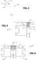
- FIGURE 4 is a schematic representation, in a sectional view, of a non-limiting exemplary embodiment of another fixing device.
- the fixing device 402 of the FIGURE 4 is a preferred embodiment example.
- Device 402 of the FIGURE 4 comprises, like the devices 102, 202 and 302, a fixing part 106 and a covering part 108.
- the thickness of the covering portion 108 decreases towards its distal end 110.
- the first cut 404 is made over a greater distance compared to the second cut 406 so that the tip of the bevel is closer to the profile.
- FIGURE 5 is a partial schematic representation, in a sectional view, of another example of the construction of a frame.
- the 500 frame shown in the FIGURE 5 , implements the fixing device 402 of the FIGURE 4 , in the configuration shown in the FIGURE 3 .
- the fabric T completely covers the covering portion 108, including the distal end 110 of the covering portion 108, and extends to the fixing portion 106 located in the groove 104 3 .
- the fabric T is fixed to the surface of the fixing portion 106 located on the side of the outer edge 104 2 of the profile 104. The edge of the fabric T is therefore located in the groove 104 3 .
- the width of the covering portion 108 is adjusted so that the covering portion 108 extends beyond the outer edge 104 2 of the profile 104.
- the distal end 110 of the covering portion 108 projects from the profile 104 in the direction opposite to that in which the fabric T extends.
- FIGURE 6 is a partial schematic representation, according to a sectional view, of a non-limiting example of an installation.
- Installation 600 shown in the FIGURE 5 , is obtained by assembling, end-on, two frames 500 1 and 500 2 , identical to frame 500 of the FIGURE 5 .
- the assembly of the frames 500 1 and 500 2 can be carried out by screwing or bolting or by any other known fixing method.
- the frame 500 1 is formed by a canvas T 1 , a frame 104 1 identical to the frame 104 of the FIGURES 1-5 and a fixing device 402 1 identical to the fixing device 402 of the FIGURE 4 .
- the frame 500 2 is formed by a canvas T 2 , a frame 104 2 identical to the frame 104 of the FIGURES 1-5 and a fixing device 402 2 identical to the fixing device 402 of the FIGURE 4 .
- each fixing device protruding from the outer edge of the frame, respectively 104 1 and 104 2 , the fixing devices 402 1 and 402 2 come into contact with each other at their respective distal ends, crush by compression against each other. This makes it possible to ensure a perfect connection and continuity between the frames 500 1 and 500 2 , in particular at the junction of these frames.
- the frames 104 1 and 104 2 are not visible.
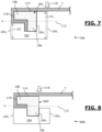
- FIGURE 7 is a schematic representation, in a sectional view, of a non-limiting exemplary embodiment of a profile according to the invention, in the usage configuration.
- the 700 frame shown in the FIGURE 7 , uses the same elements as the 300 frame of the FIGURE 3 .
- the frame 700 implements a profile 702 different from the profile 104.
- profile 702 of the FIGURE 7 has a thickness E1 between its inner edge 104 1 and the groove 104 3 which is greater compared to its thickness E2 between the groove 104 3 and its outer edge 104 2 .
- the thickness E1 is chosen so that the profile 702 and the fixing device 302 are at the same height, at the level of the fixing part 106.
- This difference in thickness can for example be obtained by reducing the thickness of a profile existing between the groove 104 3 and the outer edge 104 2 , by a desired amount. This reduction in thickness can be achieved by removing material between the groove 104 3 and the outer edge, for example by a machining process.
- this thickness difference can be provided for during the manufacture of the profile.
- FIGURE 8 is a partial schematic representation, according to a sectional view, of another non-limiting example of embodiment of a frame.
- the 800 frame shown in the FIGURE 8 , uses the same elements as the 200 frame of the FIGURE 2 .
- the frame 800 implements a fixing device 802 whose covering part 106 has a smaller thickness compared to the thickness of the covering part 106 of the fixing device 202.
- the fabric T completely covers the covering portion 108, including the distal end 110 of the covering portion 108, and extends under the covering portion and stops at the level of the fixing portion 106, or just before the fixing portion 106.
- the peripheral edge of the fabric T is inserted under the covering portion 108, so that it is wedged between the covering portion 108 and the profile 104.
- the canvas T can be fixed to the covering part 108.
- a fixing means other than a groove on the profile side. It is also possible to use other profile shapes than those shown.
Landscapes
- Engineering & Computer Science (AREA)
- Architecture (AREA)
- Civil Engineering (AREA)
- Structural Engineering (AREA)
- Physics & Mathematics (AREA)
- Electromagnetism (AREA)
- General Engineering & Computer Science (AREA)
- General Physics & Mathematics (AREA)
- Theoretical Computer Science (AREA)
- Mechanical Engineering (AREA)
- Business, Economics & Management (AREA)
- Accounting & Taxation (AREA)
- Marketing (AREA)
- Connection Of Plates (AREA)
Claims (9)
- Rahmen (100; 200; 300; 500; 800) umfassend:- eine Rahmenkonstruktion,- ein Tuch (T) und- eine Vorrichtung (102; 202; 302; 402; 802) zum abnehmbaren oder demontierbaren Befestigen des Tuchs (T) an einem Profil (104; 702) der Rahmenstruktur, das eine Innenkante (1041) und eine Außenkante (1042) aufweist, die der Innenkante (1041) gegenüberliegt, sodass sich das Tuch (T), wenn es befestigt ist, von der Seite der Innenkante (1041) erstreckt;wobei die Befestigungsvorrichtung (102; 202; 302; 402; 802) aufweist:- einen ersten Befestigungsteil (106) zum Befestigen der Vorrichtung (102; 202; 302; 402; 802) an dem Profil (104; 702) und- einen sogenannten Abdeckteil (108), der zum Abgedecktwerden durch das Tuch (102) vorgesehen ist, wobei sich der Abdeckteil (108) über den Befestigungsteil (106) hinaus zu der Außenkante (1042) hin in die Richtung (112) von der Innenkante (1041) zu der Außenkante (1042) hin erstreckt;dadurch gekennzeichnet, dass die Befestigungsvorrichtung die Form eines "Γ" oder eines "T" aufweist, dessen vertikaler Schenkel den ersten Befestigungsteil (106) ausbildet und dessen horizontaler Schenkel den Abdeckteil (108) ausbildet;und dass das Profil (702) eine Nut (1043) umfasst, die zwischen einer Innenkante (1041) und einer Außenkante (1042) des Profils (702) ausgebildet ist und zum Aufnehmen des ersten Befestigungsteils (106) der Befestigungsvorrichtung (102; 202; 302; 402; 802) vorgesehen ist, wobei das Profil (702) zwischen seiner Außenkante (1042) und der Nut (1043) eine Dicke (E2) aufweist, die geringer als seine Dicke (E1) zwischen seiner Innenkante (1041) und der Nut (1043) ist.
- Rahmen nach dem vorstehenden Anspruch,
dadurch gekennzeichnet, dass der erste Befestigungsteil (106) der Befestigungsvorrichtung (102; 202; 302; 402; 802) durch eine Zunge ausgebildet ist, die zum sich Einfügen in die Nut (1043) vorgesehen ist, die auf einer Vorderfläche des Profils (702) vorgesehen ist. - Rahmen nach einem der vorstehenden Ansprüche,
dadurch gekennzeichnet, dass der Abdeckteil (108) der Befestigungsvorrichtung (102; 402) eine solche Breite aufweist, dass er sich von dem Befestigungsteil (106) mindestens bis zu der Außenkante (1042) des Profils (104) in die Richtung (112) von der Innenkante (1041) zu der Außenkante (1042) hin erstreckt. - Rahmen nach dem vorstehenden Anspruch,
dadurch gekennzeichnet, dass der Abdeckteil (108) der Befestigungsvorrichtung (402) eine solche Breite aufweist, dass er sich von dem Befestigungsteil (106) über die Außenkante (1042) des Profils in die Richtung (112) von der Innenkante (1041) zu der Außenkante (1042) des Profils hin erstreckt. - Rahmen nach dem vorstehenden Anspruch,
dadurch gekennzeichnet, dass die obere Oberfläche (114) des Abdeckteils (108) der Befestigungsvorrichtung (402) einen distalen Abschnitt aufweist, der sich zu dem Profil (702) hin zurückzieht. - Rahmen nach einem der vorstehenden Ansprüche,
dadurch gekennzeichnet, dass die Befestigungsvorrichtung (102; 202; 302; 402; 802) ferner ein zweites Befestigungsteil zum Befestigen des Tuchs (T) an der Befestigungsvorrichtung (102; 202; 302; 402; 802) umfasst. - Rahmen nach dem vorstehenden Anspruch,
dadurch gekennzeichnet, dass der zweite Befestigungsteil der Befestigungsvorrichtung (102; 202; 302; 402) durch eine Oberfläche des ersten Befestigungsteils (106) der Befestigungsvorrichtung (102; 202; 302; 402) ausgebildet ist. - Rahmen nach einem der vorstehenden Ansprüche,
dadurch gekennzeichnet, dass für das Profil der Dickenunterschied der Dicke des Abdeckteils (108) entspricht oder größer, gegebenenfalls um die Dicke des Tuchs (T) erhöht, ist. - Einrichtung (600), die durch mehrere aneinander befestigte Rahmen (5001, 5002) nach einem der vorstehenden Ansprüche ausgebildet ist.
Applications Claiming Priority (1)
| Application Number | Priority Date | Filing Date | Title |
|---|---|---|---|
| FR1751752A FR3063529B1 (fr) | 2017-03-03 | 2017-03-03 | Dispositif de fixation d’une toile sur un profile. |
Publications (3)
| Publication Number | Publication Date |
|---|---|
| EP3369877A1 EP3369877A1 (de) | 2018-09-05 |
| EP3369877B1 true EP3369877B1 (de) | 2024-11-06 |
| EP3369877C0 EP3369877C0 (de) | 2024-11-06 |
Family
ID=59153019
Family Applications (1)
| Application Number | Title | Priority Date | Filing Date |
|---|---|---|---|
| EP18159652.9A Active EP3369877B1 (de) | 2017-03-03 | 2018-03-02 | Rahmen umfassend eine rahmenstruktur, ein gewebe und eine vorrichtung zum befestigen des gewebes auf einem profil der rahmenstruktur |
Country Status (3)
| Country | Link |
|---|---|
| US (1) | US20180251974A1 (de) |
| EP (1) | EP3369877B1 (de) |
| FR (1) | FR3063529B1 (de) |
Families Citing this family (3)
| Publication number | Priority date | Publication date | Assignee | Title |
|---|---|---|---|---|
| JP5967740B1 (ja) * | 2015-07-30 | 2016-08-10 | 株式会社リディアワークス | シートの展張装置 |
| US10773578B1 (en) * | 2019-06-08 | 2020-09-15 | Marc Poehner | Tarp securing apparatus |
| BE1031347B1 (nl) * | 2023-02-16 | 2024-09-17 | Aluvision N V | Verbeterde beursstand |
Family Cites Families (9)
| Publication number | Priority date | Publication date | Assignee | Title |
|---|---|---|---|---|
| US2526912A (en) * | 1946-06-18 | 1950-10-24 | Boeing Co | Fabric panel supporting means |
| US2784781A (en) * | 1953-06-23 | 1957-03-12 | Kaiser Aluminium Chem Corp | Framing arrangement |
| US4233765A (en) * | 1978-11-22 | 1980-11-18 | Mullan Norman P O | Frame for securing flexible sheets of material |
| US4788806A (en) * | 1986-03-20 | 1988-12-06 | Sease R Gregg | Assembly of molding strips adapted to mount flexible coverings on support surfaces |
| US4986332A (en) * | 1990-08-09 | 1991-01-22 | Craig S. Lanuza | Fastening track assembly for fabric wallcoverings |
| NL9200994A (nl) * | 1992-06-05 | 1994-01-03 | Peter Mensink | Insnapprofielsamenstel alsmede span- en opnameinrichting voor doek. |
| US7650923B2 (en) * | 2004-04-16 | 2010-01-26 | Morris Milton A | Track assembly for supporting fabrics |
| US20060231221A1 (en) * | 2004-11-16 | 2006-10-19 | Chen Chang T | Screen frame having spring spline |
| US9343005B2 (en) * | 2014-03-17 | 2016-05-17 | Rose Displays, Ltd | Extruded frame trim arrangement |
-
2017
- 2017-03-03 FR FR1751752A patent/FR3063529B1/fr active Active
-
2018
- 2018-03-02 US US15/910,281 patent/US20180251974A1/en not_active Abandoned
- 2018-03-02 EP EP18159652.9A patent/EP3369877B1/de active Active
Also Published As
| Publication number | Publication date |
|---|---|
| FR3063529B1 (fr) | 2021-12-03 |
| FR3063529A1 (fr) | 2018-09-07 |
| EP3369877A1 (de) | 2018-09-05 |
| EP3369877C0 (de) | 2024-11-06 |
| US20180251974A1 (en) | 2018-09-06 |
Similar Documents
| Publication | Publication Date | Title |
|---|---|---|
| EP3369877B1 (de) | Rahmen umfassend eine rahmenstruktur, ein gewebe und eine vorrichtung zum befestigen des gewebes auf einem profil der rahmenstruktur | |
| FR2831908A1 (fr) | Dispositif d'assemblage des bords de panneaux, lattes ou lambris | |
| FR2843769A1 (fr) | Piscine hors-sol a structure rigide | |
| FR2552467A1 (fr) | Structure arquee de couverture d'un milieu, notamment pour serres | |
| FR2950371A1 (fr) | Systeme de fixation d'une dalle pour terrasse | |
| EP2725171A1 (de) | Zaunpaneel, das ohne Verschweißen zusammengebaut wird, und mit einem solchen Paneel ausgestatteter Zaun und Bausatz | |
| EP3669037A1 (de) | Vorrichtung zur herstellung eines verstärkten schwimmbeckens | |
| EP1108898B1 (de) | Befestigungsklammer für weiches Material | |
| FR2962468A1 (fr) | Dispositif de fixation de la structure d'une piscine | |
| EP0994994B1 (de) | Paneele für eine schwimmbadwand | |
| FR3054009A1 (fr) | Accessoire pour ensemble formant raccord avec systeme anti-perforation | |
| FR2975717A1 (fr) | Insert dissociable de blocage vertical entre deux lames d'une structure plane de parement ou de parquet. | |
| WO2017029439A1 (fr) | Ancre dynamique de levage d'un element de construction, renforcee | |
| CA2459929A1 (fr) | Panneaux modulaires pour la realisation de bassin de piscine | |
| FR2825734A1 (fr) | Dispositif d'assemblage de panneaux, lattes ou lambris, a repartition de forces | |
| FR2672918A1 (fr) | Element d'encadrement de plaque; notamment pour la realisation de parois de batiment. | |
| EP3181775A1 (de) | Gründach | |
| EP2501876B1 (de) | Aus einem satz montagefertiger separater teile geformtes geländer | |
| FR2981378A1 (fr) | Dispositif pour la realisation d'un bassin de piscine | |
| FR3091889A1 (fr) | Elément rigide pour un système de couverture de piscine | |
| FR3074817A1 (fr) | Element modulaire de caniveau | |
| FR2703114A1 (fr) | Dispositif d'assemblage d'au moins deux plaques, notamment en tôle mince. | |
| EP0323940A1 (de) | Schutzschirm | |
| WO2017001527A1 (fr) | Dispositif de fixation d'element(s) de couverture pour abri de culture, abri de culture muni de tels dispositifs | |
| FR2826392A1 (fr) | Dispositif d'assemblage des bords de panneaux, lattes ou lambris |
Legal Events
| Date | Code | Title | Description |
|---|---|---|---|
| PUAI | Public reference made under article 153(3) epc to a published international application that has entered the european phase |
Free format text: ORIGINAL CODE: 0009012 |
|
| STAA | Information on the status of an ep patent application or granted ep patent |
Free format text: STATUS: THE APPLICATION HAS BEEN PUBLISHED |
|
| AK | Designated contracting states |
Kind code of ref document: A1 Designated state(s): AL AT BE BG CH CY CZ DE DK EE ES FI FR GB GR HR HU IE IS IT LI LT LU LV MC MK MT NL NO PL PT RO RS SE SI SK SM TR |
|
| AX | Request for extension of the european patent |
Extension state: BA ME |
|
| STAA | Information on the status of an ep patent application or granted ep patent |
Free format text: STATUS: REQUEST FOR EXAMINATION WAS MADE |
|
| 17P | Request for examination filed |
Effective date: 20190228 |
|
| RBV | Designated contracting states (corrected) |
Designated state(s): AL AT BE BG CH CY CZ DE DK EE ES FI FR GB GR HR HU IE IS IT LI LT LU LV MC MK MT NL NO PL PT RO RS SE SI SK SM TR |
|
| STAA | Information on the status of an ep patent application or granted ep patent |
Free format text: STATUS: EXAMINATION IS IN PROGRESS |
|
| 17Q | First examination report despatched |
Effective date: 20211209 |
|
| GRAP | Despatch of communication of intention to grant a patent |
Free format text: ORIGINAL CODE: EPIDOSNIGR1 |
|
| STAA | Information on the status of an ep patent application or granted ep patent |
Free format text: STATUS: GRANT OF PATENT IS INTENDED |
|
| INTG | Intention to grant announced |
Effective date: 20240620 |
|
| GRAS | Grant fee paid |
Free format text: ORIGINAL CODE: EPIDOSNIGR3 |
|
| GRAA | (expected) grant |
Free format text: ORIGINAL CODE: 0009210 |
|
| STAA | Information on the status of an ep patent application or granted ep patent |
Free format text: STATUS: THE PATENT HAS BEEN GRANTED |
|
| AK | Designated contracting states |
Kind code of ref document: B1 Designated state(s): AL AT BE BG CH CY CZ DE DK EE ES FI FR GB GR HR HU IE IS IT LI LT LU LV MC MK MT NL NO PL PT RO RS SE SI SK SM TR |
|
| REG | Reference to a national code |
Ref country code: GB Ref legal event code: FG4D Free format text: NOT ENGLISH |
|
| REG | Reference to a national code |
Ref country code: CH Ref legal event code: EP |
|
| REG | Reference to a national code |
Ref country code: DE Ref legal event code: R096 Ref document number: 602018076183 Country of ref document: DE |
|
| REG | Reference to a national code |
Ref country code: IE Ref legal event code: FG4D Free format text: LANGUAGE OF EP DOCUMENT: FRENCH |
|
| U01 | Request for unitary effect filed |
Effective date: 20241114 |
|
| U07 | Unitary effect registered |
Designated state(s): AT BE BG DE DK EE FI FR IT LT LU LV MT NL PT RO SE SI Effective date: 20241128 |
|
| PG25 | Lapsed in a contracting state [announced via postgrant information from national office to epo] |
Ref country code: HR Free format text: LAPSE BECAUSE OF FAILURE TO SUBMIT A TRANSLATION OF THE DESCRIPTION OR TO PAY THE FEE WITHIN THE PRESCRIBED TIME-LIMIT Effective date: 20241106 Ref country code: IS Free format text: LAPSE BECAUSE OF FAILURE TO SUBMIT A TRANSLATION OF THE DESCRIPTION OR TO PAY THE FEE WITHIN THE PRESCRIBED TIME-LIMIT Effective date: 20250306 |
|
| PG25 | Lapsed in a contracting state [announced via postgrant information from national office to epo] |
Ref country code: ES Free format text: LAPSE BECAUSE OF FAILURE TO SUBMIT A TRANSLATION OF THE DESCRIPTION OR TO PAY THE FEE WITHIN THE PRESCRIBED TIME-LIMIT Effective date: 20241106 |
|
| PG25 | Lapsed in a contracting state [announced via postgrant information from national office to epo] |
Ref country code: NO Free format text: LAPSE BECAUSE OF FAILURE TO SUBMIT A TRANSLATION OF THE DESCRIPTION OR TO PAY THE FEE WITHIN THE PRESCRIBED TIME-LIMIT Effective date: 20250206 |
|
| PG25 | Lapsed in a contracting state [announced via postgrant information from national office to epo] |
Ref country code: GR Free format text: LAPSE BECAUSE OF FAILURE TO SUBMIT A TRANSLATION OF THE DESCRIPTION OR TO PAY THE FEE WITHIN THE PRESCRIBED TIME-LIMIT Effective date: 20250207 |
|
| PG25 | Lapsed in a contracting state [announced via postgrant information from national office to epo] |
Ref country code: PL Free format text: LAPSE BECAUSE OF FAILURE TO SUBMIT A TRANSLATION OF THE DESCRIPTION OR TO PAY THE FEE WITHIN THE PRESCRIBED TIME-LIMIT Effective date: 20241106 |
|
| PG25 | Lapsed in a contracting state [announced via postgrant information from national office to epo] |
Ref country code: RS Free format text: LAPSE BECAUSE OF FAILURE TO SUBMIT A TRANSLATION OF THE DESCRIPTION OR TO PAY THE FEE WITHIN THE PRESCRIBED TIME-LIMIT Effective date: 20250206 |
|
| U20 | Renewal fee for the european patent with unitary effect paid |
Year of fee payment: 8 Effective date: 20250327 |
|
| PG25 | Lapsed in a contracting state [announced via postgrant information from national office to epo] |
Ref country code: SM Free format text: LAPSE BECAUSE OF FAILURE TO SUBMIT A TRANSLATION OF THE DESCRIPTION OR TO PAY THE FEE WITHIN THE PRESCRIBED TIME-LIMIT Effective date: 20241106 |
|
| PG25 | Lapsed in a contracting state [announced via postgrant information from national office to epo] |
Ref country code: SK Free format text: LAPSE BECAUSE OF FAILURE TO SUBMIT A TRANSLATION OF THE DESCRIPTION OR TO PAY THE FEE WITHIN THE PRESCRIBED TIME-LIMIT Effective date: 20241106 |
|
| PG25 | Lapsed in a contracting state [announced via postgrant information from national office to epo] |
Ref country code: CZ Free format text: LAPSE BECAUSE OF FAILURE TO SUBMIT A TRANSLATION OF THE DESCRIPTION OR TO PAY THE FEE WITHIN THE PRESCRIBED TIME-LIMIT Effective date: 20241106 |
|
| PLBE | No opposition filed within time limit |
Free format text: ORIGINAL CODE: 0009261 |
|
| STAA | Information on the status of an ep patent application or granted ep patent |
Free format text: STATUS: NO OPPOSITION FILED WITHIN TIME LIMIT |
|
| PG25 | Lapsed in a contracting state [announced via postgrant information from national office to epo] |
Ref country code: MC Free format text: LAPSE BECAUSE OF FAILURE TO SUBMIT A TRANSLATION OF THE DESCRIPTION OR TO PAY THE FEE WITHIN THE PRESCRIBED TIME-LIMIT Effective date: 20241106 |
|
| 26N | No opposition filed |
Effective date: 20250807 |
|
| REG | Reference to a national code |
Ref country code: CH Ref legal event code: H13 Free format text: ST27 STATUS EVENT CODE: U-0-0-H10-H13 (AS PROVIDED BY THE NATIONAL OFFICE) Effective date: 20251023 |
|
| GBPC | Gb: european patent ceased through non-payment of renewal fee |
Effective date: 20250302 |
|
| PG25 | Lapsed in a contracting state [announced via postgrant information from national office to epo] |
Ref country code: GB Free format text: LAPSE BECAUSE OF NON-PAYMENT OF DUE FEES Effective date: 20250302 |
|
| PG25 | Lapsed in a contracting state [announced via postgrant information from national office to epo] |
Ref country code: CH Free format text: LAPSE BECAUSE OF NON-PAYMENT OF DUE FEES Effective date: 20250331 |
|
| PG25 | Lapsed in a contracting state [announced via postgrant information from national office to epo] |
Ref country code: IE Free format text: LAPSE BECAUSE OF NON-PAYMENT OF DUE FEES Effective date: 20250302 |