EP3369882B1 - Entraînement à chaîne en poussée et station à chaîne - Google Patents
Entraînement à chaîne en poussée et station à chaîne Download PDFInfo
- Publication number
- EP3369882B1 EP3369882B1 EP18159719.6A EP18159719A EP3369882B1 EP 3369882 B1 EP3369882 B1 EP 3369882B1 EP 18159719 A EP18159719 A EP 18159719A EP 3369882 B1 EP3369882 B1 EP 3369882B1
- Authority
- EP
- European Patent Office
- Prior art keywords
- chain
- guide
- thrust
- station
- straight
- Prior art date
- Legal status (The legal status is an assumption and is not a legal conclusion. Google has not performed a legal analysis and makes no representation as to the accuracy of the status listed.)
- Active
Links
Images

Classifications
-
- E—FIXED CONSTRUCTIONS
- E05—LOCKS; KEYS; WINDOW OR DOOR FITTINGS; SAFES
- E05F—DEVICES FOR MOVING WINGS INTO OPEN OR CLOSED POSITION; CHECKS FOR WINGS; WING FITTINGS NOT OTHERWISE PROVIDED FOR, CONCERNED WITH THE FUNCTIONING OF THE WING
- E05F11/00—Man-operated mechanisms for operating wings, including those which also operate the fastening
- E05F11/02—Man-operated mechanisms for operating wings, including those which also operate the fastening for wings in general, e.g. fanlights
- E05F11/04—Man-operated mechanisms for operating wings, including those which also operate the fastening for wings in general, e.g. fanlights with cords, chains or cables
- E05F11/06—Man-operated mechanisms for operating wings, including those which also operate the fastening for wings in general, e.g. fanlights with cords, chains or cables in guide-channels
-
- E—FIXED CONSTRUCTIONS
- E05—LOCKS; KEYS; WINDOW OR DOOR FITTINGS; SAFES
- E05F—DEVICES FOR MOVING WINGS INTO OPEN OR CLOSED POSITION; CHECKS FOR WINGS; WING FITTINGS NOT OTHERWISE PROVIDED FOR, CONCERNED WITH THE FUNCTIONING OF THE WING
- E05F15/00—Power-operated mechanisms for wings
- E05F15/60—Power-operated mechanisms for wings using electrical actuators
- E05F15/603—Power-operated mechanisms for wings using electrical actuators using rotary electromotors
- E05F15/611—Power-operated mechanisms for wings using electrical actuators using rotary electromotors for swinging wings
- E05F15/616—Power-operated mechanisms for wings using electrical actuators using rotary electromotors for swinging wings operated by push-pull mechanisms
- E05F15/619—Power-operated mechanisms for wings using electrical actuators using rotary electromotors for swinging wings operated by push-pull mechanisms using flexible or rigid rack-and-pinion arrangements
-
- F—MECHANICAL ENGINEERING; LIGHTING; HEATING; WEAPONS; BLASTING
- F16—ENGINEERING ELEMENTS AND UNITS; GENERAL MEASURES FOR PRODUCING AND MAINTAINING EFFECTIVE FUNCTIONING OF MACHINES OR INSTALLATIONS; THERMAL INSULATION IN GENERAL
- F16G—BELTS, CABLES, OR ROPES, PREDOMINANTLY USED FOR DRIVING PURPOSES; CHAINS; FITTINGS PREDOMINANTLY USED THEREFOR
- F16G13/00—Chains
- F16G13/18—Chains having special overall characteristics
- F16G13/20—Chains having special overall characteristics stiff; Push-pull chains
-
- E—FIXED CONSTRUCTIONS
- E05—LOCKS; KEYS; WINDOW OR DOOR FITTINGS; SAFES
- E05Y—INDEXING SCHEME ASSOCIATED WITH SUBCLASSES E05D AND E05F, RELATING TO CONSTRUCTION ELEMENTS, ELECTRIC CONTROL, POWER SUPPLY, POWER SIGNAL OR TRANSMISSION, USER INTERFACES, MOUNTING OR COUPLING, DETAILS, ACCESSORIES, AUXILIARY OPERATIONS NOT OTHERWISE PROVIDED FOR, APPLICATION THEREOF
- E05Y2201/00—Constructional elements; Accessories therefor
- E05Y2201/10—Covers; Housings
-
- E—FIXED CONSTRUCTIONS
- E05—LOCKS; KEYS; WINDOW OR DOOR FITTINGS; SAFES
- E05Y—INDEXING SCHEME ASSOCIATED WITH SUBCLASSES E05D AND E05F, RELATING TO CONSTRUCTION ELEMENTS, ELECTRIC CONTROL, POWER SUPPLY, POWER SIGNAL OR TRANSMISSION, USER INTERFACES, MOUNTING OR COUPLING, DETAILS, ACCESSORIES, AUXILIARY OPERATIONS NOT OTHERWISE PROVIDED FOR, APPLICATION THEREOF
- E05Y2201/00—Constructional elements; Accessories therefor
- E05Y2201/60—Suspension or transmission members; Accessories therefor
- E05Y2201/622—Suspension or transmission members elements
- E05Y2201/644—Flexible elongated pulling elements
- E05Y2201/656—Chains
-
- E—FIXED CONSTRUCTIONS
- E05—LOCKS; KEYS; WINDOW OR DOOR FITTINGS; SAFES
- E05Y—INDEXING SCHEME ASSOCIATED WITH SUBCLASSES E05D AND E05F, RELATING TO CONSTRUCTION ELEMENTS, ELECTRIC CONTROL, POWER SUPPLY, POWER SIGNAL OR TRANSMISSION, USER INTERFACES, MOUNTING OR COUPLING, DETAILS, ACCESSORIES, AUXILIARY OPERATIONS NOT OTHERWISE PROVIDED FOR, APPLICATION THEREOF
- E05Y2201/00—Constructional elements; Accessories therefor
- E05Y2201/60—Suspension or transmission members; Accessories therefor
- E05Y2201/622—Suspension or transmission members elements
- E05Y2201/658—Members cooperating with flexible elongated pulling elements
- E05Y2201/66—Deflectors; Guides
-
- E—FIXED CONSTRUCTIONS
- E05—LOCKS; KEYS; WINDOW OR DOOR FITTINGS; SAFES
- E05Y—INDEXING SCHEME ASSOCIATED WITH SUBCLASSES E05D AND E05F, RELATING TO CONSTRUCTION ELEMENTS, ELECTRIC CONTROL, POWER SUPPLY, POWER SIGNAL OR TRANSMISSION, USER INTERFACES, MOUNTING OR COUPLING, DETAILS, ACCESSORIES, AUXILIARY OPERATIONS NOT OTHERWISE PROVIDED FOR, APPLICATION THEREOF
- E05Y2201/00—Constructional elements; Accessories therefor
- E05Y2201/60—Suspension or transmission members; Accessories therefor
- E05Y2201/622—Suspension or transmission members elements
- E05Y2201/658—Members cooperating with flexible elongated pulling elements
- E05Y2201/668—Pulleys; Wheels
-
- E—FIXED CONSTRUCTIONS
- E05—LOCKS; KEYS; WINDOW OR DOOR FITTINGS; SAFES
- E05Y—INDEXING SCHEME ASSOCIATED WITH SUBCLASSES E05D AND E05F, RELATING TO CONSTRUCTION ELEMENTS, ELECTRIC CONTROL, POWER SUPPLY, POWER SIGNAL OR TRANSMISSION, USER INTERFACES, MOUNTING OR COUPLING, DETAILS, ACCESSORIES, AUXILIARY OPERATIONS NOT OTHERWISE PROVIDED FOR, APPLICATION THEREOF
- E05Y2201/00—Constructional elements; Accessories therefor
- E05Y2201/60—Suspension or transmission members; Accessories therefor
- E05Y2201/622—Suspension or transmission members elements
- E05Y2201/71—Toothed gearing
- E05Y2201/722—Racks
- E05Y2201/724—Flexible
-
- E—FIXED CONSTRUCTIONS
- E05—LOCKS; KEYS; WINDOW OR DOOR FITTINGS; SAFES
- E05Y—INDEXING SCHEME ASSOCIATED WITH SUBCLASSES E05D AND E05F, RELATING TO CONSTRUCTION ELEMENTS, ELECTRIC CONTROL, POWER SUPPLY, POWER SIGNAL OR TRANSMISSION, USER INTERFACES, MOUNTING OR COUPLING, DETAILS, ACCESSORIES, AUXILIARY OPERATIONS NOT OTHERWISE PROVIDED FOR, APPLICATION THEREOF
- E05Y2900/00—Application of doors, windows, wings or fittings thereof
- E05Y2900/10—Application of doors, windows, wings or fittings thereof for buildings or parts thereof
- E05Y2900/13—Type of wing
- E05Y2900/148—Windows
Definitions
- the invention relates to a chain drive and a chain station with the features in the preamble of the independent claims.
- Such a chain station and chain drive are from the DE 20 2011 050 625 U1 known.
- the chain station has a U-shaped chain guide which is bent once and which has three straight guide sections and only a single bent guide section between straight guide sections.
- the chain guide only engages in the linear chain on both sides in the first straight guide section.
- One-sided engagement takes place in the second and third straight guide section.
- the push chain folds in automatically, its front end piece being caught with a protruding pin in a groove on the curved guide section.
- the fold or kink moves from the curved guide section along these two straight guide sections to the end.
- a channel-shaped and spirally wound chain holder forms the outer guide for a push chain with a closed back.
- the EP 2 653 641 A2 shows a similar chain station, in which a chain deflection has a sharp edge in order to save space and overall height of the chain station.
- the invention solves this problem with the features in claim 1.
- the claimed chain drive technology ie the chain drive, the chain station and the drive method, have various advantages.
- the chain station is used to accommodate the retracted push chain of the chain drive in a loop or spiral shape.
- the chain station can be fixed or loosely mounted in a housing of the chain drive. By varying the length of the station, different chain lengths can be accommodated.
- the chain guide of the chain station that engages the push chain on both sides, i.e. on opposite sides, can guide the push chain on its rotatable rollers or on the chain pins, in particular on sleeves that have been drawn on, particularly well and safely and without tilting.
- wear on the chain station and on the push chain is reduced.
- the resistance in the chain station, especially at chain deflections, when retracting and extending the push chain is reduced.
- the drive power can be better utilized and used more economically.
- the claimed chain drive technology is able to move large and heavy sashes. This is possible even in difficult locations, for example with relatively flat roof windows on glass facades.
- the push chain can also with a predominantly extend upright or vertical directional component and engage the sash.
- the chain guide forms a spiral-like and continuous guide track for the rotatable rollers or chain pins or sleeves.
- the push chain can be guided in the chain station free of constraints and in particular with soft curves in a multi-thread loop or a spiral shape.
- the guide track has several straight and rounded guide sections.
- the guide track is designed as a slot-like free space between the respective straight and curved guide elements. The rollers or chain pins or sleeves can thus be guided on the top and bottom with sufficient play and great security.
- the stressed chain guide is also favorable for the safe bending of the push chain held in the chain station at the chain deflections.
- the straight guide elements of the chain guide can be designed like webs and engage in an inner free space on the top and bottom of the push chain between laterally spaced chain links. You can be adapted to the free space and its dimensions. A favorable guide play can be set here.
- a curved inner guide element as a rotatable guide roller is advantageous for a safe, soft and low-resistance chain guide.
- a guide roller does indeed distance the subsequent straight guide sections and the chain sections there.
- the gain in leadership quality can offset the slight increase in the construction height of the chain station.
- Such a guide roller is particularly suitable for a strong chain deflection with a 180 ° angle and a small deflection radius.
- Another curved inner guide element can be designed as a stationary and round curved guide bar. This is particularly advantageous for a spiral-like curved guide track and a greater height spacing of the subsequent straight guide sections. Such a guide bar saves space along the length of the chain station.
- the respectively assigned curved outer guide element can be designed as a web-like round curved guide.
- the curved guide elements also lead in the said free spaces of the push chain.
- the chain station can have an open frame or a circumferentially closed housing.
- the frame or housing can have a channel-shaped chain holder with straight holder sections.
- one or more curved receiving sections can be provided for a continuous chain receiving. These can be formed e.g. by housing extensions.
- the curved receiving sections can alternatively be omitted, the push chain lying open on the chain deflectors and being guided on the curved guide sections there.
- the frame or housing of the chain station can be correspondingly shortened while leaving out these one or more chain deflections and only have the straight receiving sections.
- Such a design is particularly inexpensive and inexpensive. It also enables an easy and inexpensive length adjustment of the chain station to different push chain lengths.
- the chain thrust drive used is variable and can be adapted to different purposes, installation conditions and loads adapt in the manner of a modular system with little effort.
- the chain holder can have two or more straight and parallel holder sections. There are preferably three straight receiving sections. Their number can be more than three. This design allows a large chain length to be accommodated in a loop or spiral shape and with a constant bending direction in a compact chain station.
- the straight and curved guide elements can be arranged on the frame or housing. They can protrude into the chain holder on both sides or from opposite directions and there into the upper and lower spaces between the side plates of the linear chain.
- the chain holder can cover and shield the chain links on their upper and lower sides and, if necessary, also on the other sides.
- the design of the push chain with inner and outer link plates on both sides with an adapted curved support contour between the adjacent outer link plates is of particular advantage for the claimed design of the chain station and the chain guide.
- the linear chain can thus do without a closed back and still has a high degree of rigidity and strength. It can also be used as a heavy-duty chain for heavy-weight leaves.
- the low-resistance chain guide is particularly advantageous for this.
- the linear chain can be guided equally well and safely at the chain deflectors when subjected to tensile and shear loads.
- the push chain can have a front mouthpiece and a rear end piece with a means of limiting its extension length. This prevents the push chain from being accidentally driven out by an outside of the Chain station arranged propellant of the drive, in particular a sprocket, avoided.
- the drive unit of the chain drive can have a motor, a transmission and a chain wheel or some other drive means.
- a brushless electric motor is preferably used as the motor. This has a particularly high degree of efficiency, which optimally complements the guide quality and the low resistance or friction of the chain guide.
- the claimed chain thrust drive and the claimed chain station can have the following advantageous further embodiments individually or in combination.
- the chain holder can have two or more, in particular three, straight and parallel holder sections.
- the chain holder can cover the chain links on their top and bottom and, if necessary, on the sides.
- the push chain can have a front mouthpiece and a rear end piece with a means of limiting its extension length.
- the invention relates to a chain drive (1), a chain station (11) and a drive method for movable leaves.
- the movable sashes can be window sashes or flaps or other movable, in particular pivotable, building parts or opening locks, e.g. also doors, be.
- the wings can also be designed as hoods, domes, domes or the like.
- the blades can be parts of smoke and heat extraction systems (RWA), automated natural ventilation or the like. They are opened and closed by the chain drive (1).
- the chain drive (1) can be arranged in any position on the stationary frame for the wing.
- the sash is part of a roof window that is slightly inclined to the horizontal and is actuated by a chain drive (1) installed upright in the surrounding window frame.
- the chain drive (1) can alternatively also be attached to or built into the sash.
- the chain drive (1) shown has a motorized extendable push chain (10). This has a mouthpiece (19) at its front free end, to which a bearing block (not shown) can preferably be pivotably connected and is connected to the movable wing.
- the chain feed drive (1) can have two or more push chains (10).
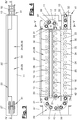
- the chain drive (1) has a housing (2) in which a drive unit (3) and a chain station (11) are arranged in a spiral shape for the space-saving reception of the retracted push chain (10).
- the housing (2) can, for example, be designed as a hollow extruded profile, on the jacket of which a chain outlet (9) for the push chain (10) is arranged and the ends of which are closed with suitable covers.
- a connection (8) for supplying the chain thrust drive (1) can be arranged on one side of the housing, in particular on the end face.
- electrical power and / or control signals can be transmitted here. these can For example, from an external mobile or stationary as well as wired or wireless control device (not shown), from a higher-level building or fire control, from adjacent chain drives (1) or the like that work in a network.
- the drive unit (3) has a motor (4), a downstream gear (5) and a drive means (6) for the push chain (10), which is designed, for example, as a sprocket.
- the motor (4) is preferably designed as an electric motor which can be operated with AC mains voltage or with a lower DC voltage. It is preferably a brushless electric motor.
- the drive unit (3) can have an emergency release in the event of a blockage.
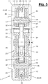
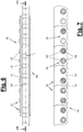
- the push chain (10) is in Figure 4 and 5 such as Figures 6 and 7 shown.
- FIG. 4 and 5 it is designed as a roller chain with rotatable rollers (17) on the chain links (12).
- the chain links (12) each have a pair of outer link plates (13) and inner link plates (14) on both sides.
- the pairings are laterally spaced apart transversely to the longitudinal direction of the chain and each form a free space (18) between them on the top and bottom.
- the chain links (12) each have chain pins (16) which transversely connect the plate pairings with one another and offer the chain links (12) a rotational mobility at chain deflections.
- the chain pins (16) can according to Figure 5 consist of an inner bolt (16 ') for connecting the outer link plates (13) and a pulled-on sleeve (16 ") for connecting the inner link plates (14).
- the rollers (17) are between the link plate pairing and freely rotatable on the chain pin (16), in particular on the sleeve (16 ").
- the push chain (10) has a rigid back. It can transmit shear forces when it is extended while maintaining its straight extension. In particular, the push chain (10) can extend out of the housing (2) in the vertical direction and raise a wing.
- the push chain (10) can be designed as a heavy-duty chain.
- the outer and inner link plates (13, 14) have a flat or planar disk or plate shape.
- the inner and outer link plates (13, 14) overlap one another in the longitudinal direction of the chain and are connected to one another by the chain pins (16).
- the outer link plates (13) abutting one another in the longitudinal direction of the chain have a mutually adapted and preferably curved support contour (15). They are supported on one another at the front.
- the chain pins (16) are according to Figure 4 Arranged eccentrically seen in the longitudinal direction of the chain. They are arranged closer to the front than to the back of the chain links (12) and their link plates (13, 14). The free spaces (18) have accordingly Figure 5 a different depth.
- the link plates (13, 14) are provided with a wave shape or rounded shape on the front in the area of the chain pins (16).
- the back or top of the link plates (13, 14) is straight.
- the contact points of the support contour (15) located on the end faces of the outer link plates (13) are curved and are spaced apart from the row of chain pins (16). This is favorable for a high back stiffness of the push chain (10).
- the push chain (10) has an end piece (20).
- This can be provided with a limiting means (21) for the extension length of the push chain (10).
- the limiting means (21) can be formed, for example, by a pin protruding laterally over the end piece (20), in particular by an elongated chain pin, which runs against a stop in front of or on the chain wheel.
- the chain station (11) has a chain guide (28) which according to FIG Figure 4 and 5 engages on both sides in the push chain (10) and guides the rotatable rollers (17).
- the chain guide (28) engages on opposite sides of the push chain (10) and on the upper and lower free spaces (18) there.
- the chain guide (28) guides the linear chain (10) in the chain station (11).
- the chain guide (28) has a spiral-like guide track (29) with several straight and rounded guide sections (30, 31).
- the curved guide sections (31) form chain deflections between straight guide sections (30). In the preferred embodiment shown, there are three parallel straight guide sections (30) and two opposite curved guide sections (31) or chain deflectors.
- the guide track (29) is designed as a slot-like free space between the inner and outer guide elements of the chain guide (28).
- the guide track (29) is preferably formed continuously. It extends from an entrance (41) on one end face of the chain station (11) to an end (42), which for example is arranged other opposite end face area.
- the slot-like guide track (29) is formed in the straight guide sections (30) between a plurality of straight and parallel guide elements (32, 33). In the curved guide sections (31), the guide track (29) is formed between the inner and outer curved guide elements (37, 38, 39, 40).
- the straight guide elements (32, 33) are web-like. They are adapted to the respective inner free space (18) of the linear chain (10) and intervene here. They protrude up to the vicinity of the rotatable rollers (17), with a suitable guide clearance being provided by the spacing.
- the straight guide elements (32,33) have according to Figure 5 a different length.
- a curved inner guide element (37) is designed as a freely rotatable guide roller. This moves with the deflection of the running linear chain (10).
- the associated curved outer guide element (39) is designed as a web-like round arched guide.
- the other curved inner guide element (38) is designed as a stationary and rounded guide bar.
- the associated outer curved guide element (40) is in turn designed as a web-like round curved guide.
- the curved guide elements (37, 38, 39, 40) are each attached to the front side of the housing or frame (22) of the chain station (11).
- the chain station (11) has according to Figures 3 to 5 a housing (22) which preferably encloses the received push chain (10) on all sides.
- a housing (22) which preferably encloses the received push chain (10) on all sides.
- a skeletal or frame-like frame with lateral openings can be provided instead of the housing.
- the straight guide elements (32, 33) are arranged in the housing or frame (22).
- the curved guide elements (37, 38, 39, 40) are each attached to the front side of the housing or frame (22) of the chain station (11).
- the frame or housing (22) has a channel-shaped chain seat (23) with straight seat sections (24, 25, 26).
- the chain holder (23) has two or more, in particular three, straight and parallel holder sections (24, 25, 26).
- Such curved receiving sections (27) can be arranged on one or both end faces of the chain station (11).
- the chain holder (23) can thus have a spiral-like and circumferential channel shape.
- the curved receiving sections are missing, the chain station (11) only having the straight receiving sections (24, 25, 26).
- the first receiving section (24) forms the access (41) with its front opening and is open on both front sides.
- the receiving section (25) located above it is open on one end face adjacent to the access (41).
- the opposite end forms the end (42) and is closed.
- the uppermost and third receiving section (26) is open at both ends.
- the push chain (10) arriving at the entrance (41) reaches the top third receiving section (26) via the first, lower receiving section (24) and the chain deflector with the larger radius that adjoins the face and then via the other chain deflection with the narrower radius in the middle receiving section (25). You will be on the guide track (29) and the straight and curved guide sections (30,31) out.
- the guide elements (32,33,37,38,39,40) are arranged on the frame or housing (22) and protrude into the chain holder (23) on both sides or on opposite sides. Said straight guide elements can be molded onto the frame or housing (22).
- Figure 5 shows such a configuration with a housing (22) designed, for example, as an injection molded part made of plastic or as an extruded part made of metal.
- the chain holder (23) covers the chain links (12) on their top and bottom. In the case of the closed shape of the housing, there is also a cover on the two side surfaces.
- the push chain (10) is pushed into the chain station (11) by the drive unit (3) and pulled out again.
- the rollers (17) are guided and supported on the rounded outer guide elements (39, 40) of the chain deflectors or curved guide sections (31).
- the rollers (17) are guided and supported on the inner curved guide elements (37, 38). They roll along the said guide elements (37,38,396,40).
- the sleeves (16 ") pulled onto the inner bolt (16 ') are rotatable or rigidly arranged in the receiving openings of the inner link plates (14). They can, for example, be pressed into the receiving openings in the manner of a sleeve chain.
- the sleeves (16") roll or slide along said guide elements (37,38,396,40).
- the push chain (10) is otherwise designed in the same way as in the first exemplary embodiment.
- the chain station (11) and the other components of the chain push drive ((1) are shown in the manner described above Figure 1 to 5 educated.
- the chain guide (28) engaging on both sides in the push chain (10) and its free spaces (18) makes contact and guides the sleeves (16 ").
Landscapes
- Engineering & Computer Science (AREA)
- General Engineering & Computer Science (AREA)
- Mechanical Engineering (AREA)
- Devices For Conveying Motion By Means Of Endless Flexible Members (AREA)
Claims (13)
- Station à chaîne pour une chaîne de poussée à plusieurs maillons (10) d'un entraînement à chaîne en poussée (1) pour des battants mobiles, notamment des battants de fenêtre ou des clapets, la station à chaîne (11) comprenant un guide de chaîne (28), qui est apte à pénétrer des deux côtés dans la chaîne de poussée (10), le guide de chaîne (28) comprenant une voie de guidage en spirale et continue (29) munie de plusieurs sections de guidage droites et incurvées en rond (30, 31), les sections de guidage incurvées (31) formant des déviations de chaîne entre des sections de guidage droites (30), et la voie de guidage (29) étant configurée sous la forme d'un espace libre en forme de fente entre des éléments de guidage droits (32, 33) et des éléments de guidage incurvés (37, 38, 39, 40), et la voie de guidage en forme de fente (29) étant formée dans les sections de guidage droites (30) à chaque fois entre plusieurs éléments de guidage droits et parallèles (32, 33), et étant formée dans les sections de guidage incurvées (31) entre des éléments de guidage incurvés intérieurs et extérieurs (37, 38, 39, 40).
- Station à chaîne selon la revendication 1, caractérisée en ce qu'un élément de guidage intérieur incurvé (37, 38) est configuré sous la forme d'un rouleau de guidage rotatif ou sous la forme d'une barre de guidage stationnaire incurvée en rond, et les éléments de guidage extérieurs incurvés (39, 40) sont de préférence configurés sous la forme de guides curvilignes ronds en forme de traverse.
- Station à chaîne selon la revendication 1 ou 2, caractérisée en ce que les éléments de guidage droits (32, 33) du guide de chaîne (28) sont configurés en forme de traverse et peuvent pénétrer dans un espace libre intérieur (18) sur le côté supérieur et inférieur de la chaîne de poussée (10) entre des brides de chaîne espacées latéralement (13, 14).
- Station à chaîne selon la revendication 1, 2 ou 3 caractérisée en ce que le guide de chaîne (28) comprend trois sections de guidage droites parallèles (30) et deux sections de guidage incurvées opposées l'une à l'autre (31).
- Entraînement à chaîne en poussée pour des battants mobiles, notamment des battants de fenêtre ou des clapets, l'entraînement à chaîne en poussée (1) comprenant une chaîne de poussée à plusieurs maillons (10) et une station à chaîne (11) selon la revendication 1, 2, 3 ou 4, la chaîne de poussée (10) étant configurée sous la forme d'une chaîne à rouleaux munie de rouleaux rotatifs (17) sur les maillons de chaîne (12) et comprenant des boulons de chaîne (16) munis de douilles enfilées (16'') sur les maillons de chaîne (12), le guide de chaîne (28) de la station à chaîne (11) pénétrant des deux côtés dans la chaîne de poussée (10) et guidant les rouleaux (17) ou les douilles (16'').
- Entraînement à chaîne en poussée selon la revendication 5, caractérisé en ce que les éléments de guidage droits (32, 33) sont configurés en forme de traverse et adaptés à un espace libre intérieur (18) de la chaîne de poussée (10) entre des brides de chaîne espacées latéralement (13, 14).
- Entraînement à chaîne en poussée selon la revendication 5 ou 6, caractérisé en ce que la station à chaîne (11) comprend un châssis ou boîtier (22) muni d'un logement de chaîne (23) en forme de canal et éventuellement en spirale, muni de sections de logement droites et éventuellement incurvées (24, 25, 26, 27).
- Entraînement à chaîne en poussée selon la revendication 7, caractérisé en ce que les éléments de guidage (32, 33, 37, 38, 39, 40) sont agencés, de préférence formés, sur le châssis ou le boîtier (22), et dépassent des deux côtés dans le logement de chaîne (23) .
- Entraînement à chaîne en poussée selon l'une quelconque des revendications 5 à 8, caractérisé en ce que l'entraînement à chaîne en poussée (1) comprend une unité d'entraînement (3) munie d'un moteur (4), de préférence d'un moteur électrique sans balais, d'une transmission (5) et d'une roue à chaîne (6).
- Entraînement à chaîne en poussée selon l'une quelconque des revendications 5 à 9, caractérisé en ce que la chaîne de poussée (10) est configurée à dos rigide.
- Entraînement à chaîne en poussée selon l'une quelconque des revendications 5 à 10, caractérisé en ce que la chaîne de poussée (10) comprend des deux côtés des brides de chaîne intérieures et extérieures (13, 14), qui se chevauchent dans la direction longitudinale de chaîne et sont reliées par des boulons de chaîne (16) .
- Entraînement à chaîne en poussée selon la revendication 11, caractérisé en ce que les brides de chaîne extérieures (13) qui se heurtent dans la direction longitudinale de chaîne présentent un contour de support incurvé mutuellement adapté (15).
- Entraînement à chaîne en poussée selon la revendication 11 ou 12, caractérisé en ce que les rouleaux (17) sont agencés entre les brides de chaîne des deux côtés (13, 14) et sont montés de manière rotative sur des boulons de chaîne (16).
Applications Claiming Priority (1)
| Application Number | Priority Date | Filing Date | Title |
|---|---|---|---|
| DE202017101221.2U DE202017101221U1 (de) | 2017-03-03 | 2017-03-03 | Kettenschubantrieb |
Publications (3)
| Publication Number | Publication Date |
|---|---|
| EP3369882A1 EP3369882A1 (fr) | 2018-09-05 |
| EP3369882B1 true EP3369882B1 (fr) | 2021-01-27 |
| EP3369882B2 EP3369882B2 (fr) | 2024-03-13 |
Family
ID=62637052
Family Applications (1)
| Application Number | Title | Priority Date | Filing Date |
|---|---|---|---|
| EP18159719.6A Active EP3369882B2 (fr) | 2017-03-03 | 2018-03-02 | Entraînement à chaîne en poussée et station à chaîne |
Country Status (4)
| Country | Link |
|---|---|
| EP (1) | EP3369882B2 (fr) |
| DE (2) | DE202017101221U1 (fr) |
| DK (1) | DK3369882T4 (fr) |
| FI (1) | FI3369882T4 (fr) |
Families Citing this family (1)
| Publication number | Priority date | Publication date | Assignee | Title |
|---|---|---|---|---|
| EP3872585A1 (fr) * | 2020-02-26 | 2021-09-01 | Bulinfo Eood | Dispositif pour ouvrir ou fermer une fenêtre ou une porte et système et procédé pour commander et gérer la qualité de l'air de locaux intérieurs |
Citations (17)
| Publication number | Priority date | Publication date | Assignee | Title |
|---|---|---|---|---|
| US4014136A (en) | 1974-07-18 | 1977-03-29 | Teleflex Morse Limited | Means for the opening and closing of angularly movable panels |
| JPH07127332A (ja) | 1993-10-28 | 1995-05-16 | Toyo Exterior Co Ltd | 伸縮門扉用のプッシュプルチェーン収納装置 |
| DE9321472U1 (de) | 1992-10-29 | 1998-10-08 | W. Hautau Gmbh, 31691 Helpsen | Kettenantrieb mit innenliegendem Antriebsmotor |
| AU717821B2 (en) | 1995-08-02 | 2000-04-06 | L.S.K. International Research Pty. Limited | Improved chain and casement window opening and closing mechanisms incorporating same |
| DE69819386T2 (de) | 1997-03-14 | 2004-08-26 | Topp S.R.L. | Kettenantrieb |
| WO2004076792A2 (fr) | 2003-02-25 | 2004-09-10 | Vkr Holding A/S | Boitier pour actionneur a chaine |
| EP1484465A1 (fr) | 2003-06-06 | 2004-12-08 | VKR Holding A/S | Actionneur linéaire avec chaínes d'entraínement connectables par des éléments interverrouillables |
| WO2005108821A1 (fr) | 2004-05-12 | 2005-11-17 | Vkr Holding A/S | Chaine boutante et actionneur |
| DE102010010719A1 (de) | 2010-03-09 | 2011-09-15 | Vkr Holding A/S | Fensterbetätigungsvorrichtung |
| US20110302843A1 (en) | 2010-06-11 | 2011-12-15 | Dallmann Brian D | Window drive with back-curving chain |
| DE202012001208U1 (de) | 2012-02-06 | 2012-03-08 | Vkr Holding A/S | Betätigungsvorrichtung für ein Fenster oder eine Tür |
| DE202012102423U1 (de) | 2012-07-02 | 2012-07-26 | D + H Mechatronic Aktiengesellschaft | Kettenantrieb |
| WO2012122596A1 (fr) | 2011-03-16 | 2012-09-20 | Assa Abloy Australia Pty Ltd | Enrouleur de chaîne pour une fenêtre ou une porte |
| DE202011050625U1 (de) | 2011-07-04 | 2012-10-11 | D+H Mechatronic Ag | Kettenantrieb |
| EP2653641A2 (fr) | 2012-04-20 | 2013-10-23 | D+H Mechatronic AG | Entraînement à chaînes |
| CN103899180A (zh) | 2014-04-07 | 2014-07-02 | 江汇装饰用品(鹤山)有限公司 | 一种开窗器 |
| WO2016113286A1 (fr) | 2015-01-13 | 2016-07-21 | Aumüller Aumatic GmbH | Entraînement à chaîne en poussée |
-
2017
- 2017-03-03 DE DE202017101221.2U patent/DE202017101221U1/de active Active
-
2018
- 2018-03-02 DK DK18159719.6T patent/DK3369882T4/da active
- 2018-03-02 DE DE102018104796.7A patent/DE102018104796B4/de active Active
- 2018-03-02 FI FIEP18159719.6T patent/FI3369882T4/fi active
- 2018-03-02 EP EP18159719.6A patent/EP3369882B2/fr active Active
Patent Citations (17)
| Publication number | Priority date | Publication date | Assignee | Title |
|---|---|---|---|---|
| US4014136A (en) | 1974-07-18 | 1977-03-29 | Teleflex Morse Limited | Means for the opening and closing of angularly movable panels |
| DE9321472U1 (de) | 1992-10-29 | 1998-10-08 | W. Hautau Gmbh, 31691 Helpsen | Kettenantrieb mit innenliegendem Antriebsmotor |
| JPH07127332A (ja) | 1993-10-28 | 1995-05-16 | Toyo Exterior Co Ltd | 伸縮門扉用のプッシュプルチェーン収納装置 |
| AU717821B2 (en) | 1995-08-02 | 2000-04-06 | L.S.K. International Research Pty. Limited | Improved chain and casement window opening and closing mechanisms incorporating same |
| DE69819386T2 (de) | 1997-03-14 | 2004-08-26 | Topp S.R.L. | Kettenantrieb |
| WO2004076792A2 (fr) | 2003-02-25 | 2004-09-10 | Vkr Holding A/S | Boitier pour actionneur a chaine |
| EP1484465A1 (fr) | 2003-06-06 | 2004-12-08 | VKR Holding A/S | Actionneur linéaire avec chaínes d'entraínement connectables par des éléments interverrouillables |
| WO2005108821A1 (fr) | 2004-05-12 | 2005-11-17 | Vkr Holding A/S | Chaine boutante et actionneur |
| DE102010010719A1 (de) | 2010-03-09 | 2011-09-15 | Vkr Holding A/S | Fensterbetätigungsvorrichtung |
| US20110302843A1 (en) | 2010-06-11 | 2011-12-15 | Dallmann Brian D | Window drive with back-curving chain |
| WO2012122596A1 (fr) | 2011-03-16 | 2012-09-20 | Assa Abloy Australia Pty Ltd | Enrouleur de chaîne pour une fenêtre ou une porte |
| DE202011050625U1 (de) | 2011-07-04 | 2012-10-11 | D+H Mechatronic Ag | Kettenantrieb |
| DE202012001208U1 (de) | 2012-02-06 | 2012-03-08 | Vkr Holding A/S | Betätigungsvorrichtung für ein Fenster oder eine Tür |
| EP2653641A2 (fr) | 2012-04-20 | 2013-10-23 | D+H Mechatronic AG | Entraînement à chaînes |
| DE202012102423U1 (de) | 2012-07-02 | 2012-07-26 | D + H Mechatronic Aktiengesellschaft | Kettenantrieb |
| CN103899180A (zh) | 2014-04-07 | 2014-07-02 | 江汇装饰用品(鹤山)有限公司 | 一种开窗器 |
| WO2016113286A1 (fr) | 2015-01-13 | 2016-07-21 | Aumüller Aumatic GmbH | Entraînement à chaîne en poussée |
Non-Patent Citations (1)
| Title |
|---|
| VELUX: "Velux Integra KMG 100K manual ", 1 December 2013 (2013-12-01), pages 1 - 20, XP055856983 |
Also Published As
| Publication number | Publication date |
|---|---|
| DK3369882T4 (da) | 2024-06-17 |
| EP3369882B2 (fr) | 2024-03-13 |
| DE202017101221U1 (de) | 2018-06-05 |
| EP3369882A1 (fr) | 2018-09-05 |
| DE102018104796A1 (de) | 2018-09-06 |
| DE102018104796B4 (de) | 2024-09-12 |
| DK3369882T3 (da) | 2021-04-19 |
| FI3369882T4 (fi) | 2024-06-18 |
Similar Documents
| Publication | Publication Date | Title |
|---|---|---|
| EP0141805A2 (fr) | Volet à rouleau | |
| EP3805513B1 (fr) | Porte roulante | |
| EP1923533A2 (fr) | Porte roulante | |
| WO2016113286A1 (fr) | Entraînement à chaîne en poussée | |
| WO1994002705A1 (fr) | Volet roulant du type jalousie | |
| EP3369882B2 (fr) | Entraînement à chaîne en poussée et station à chaîne | |
| EP2792835A2 (fr) | Système de portes ou de fenêtres coulissantes comprenant un châssis et des vantaux de porte ou de fenêtre coulissants dans celui-ci | |
| CH635164A5 (de) | Raffstore. | |
| DE4031388C2 (de) | Seitensektionaltor oder Rundlauftor, Deckensektionaltor | |
| EP1860266B1 (fr) | Agencement d'un dispositif d'actionnement d'articulations, en particulier pour un battant de fenêtre, un cadre ou un globe d'éclairage | |
| EP1366259B1 (fr) | Porte sectionnee | |
| EP1555379A1 (fr) | Rideau à lammes | |
| EP0731247A2 (fr) | Dispositif de sécurité d'un volet enroulable autour d'un arbre | |
| EP1437475B1 (fr) | Fenêtre ou porte avec dispositif d'entraînement | |
| EP1522666B1 (fr) | Ferrure pour portes ou fenêtres à soulèvement et coulissement et chariot pour un tel ferrure. | |
| EP2475833B1 (fr) | Dispositif d'actionnement d'une porte basculante | |
| EP2905409A1 (fr) | Dispositif de réglage pour une aile et dispositif de réglage de plusieurs ailes | |
| EP1555380A1 (fr) | Rideau à lammes | |
| EP2444583B1 (fr) | Colonne de portail pour un portail roulant | |
| EP4603656A1 (fr) | Installation de protection contre les intempéries | |
| DE102006030459B4 (de) | Schwenk-Schiebe-Mechanismus für eine Fahrzeugtür | |
| EP2740869B1 (fr) | Agencement d'armature de baguette de fermeture pour une fenêtre, une porte ou analogue, ainsi que procédé d'entraînement de l'agencement d'armature de baguette de fermeture | |
| DE10353287A1 (de) | Schiebefenster mit mindestens einem Fensterflügel für den Einbau in einen Flächenausschnitt einer geneigten Fläche | |
| EP1681436B1 (fr) | Volet roulant | |
| DE19519905C2 (de) | Tür für Fahrkörbe von Aufzügen |
Legal Events
| Date | Code | Title | Description |
|---|---|---|---|
| PUAI | Public reference made under article 153(3) epc to a published international application that has entered the european phase |
Free format text: ORIGINAL CODE: 0009012 |
|
| STAA | Information on the status of an ep patent application or granted ep patent |
Free format text: STATUS: THE APPLICATION HAS BEEN PUBLISHED |
|
| AK | Designated contracting states |
Kind code of ref document: A1 Designated state(s): AL AT BE BG CH CY CZ DE DK EE ES FI FR GB GR HR HU IE IS IT LI LT LU LV MC MK MT NL NO PL PT RO RS SE SI SK SM TR |
|
| AX | Request for extension of the european patent |
Extension state: BA ME |
|
| STAA | Information on the status of an ep patent application or granted ep patent |
Free format text: STATUS: REQUEST FOR EXAMINATION WAS MADE |
|
| 17P | Request for examination filed |
Effective date: 20190228 |
|
| RBV | Designated contracting states (corrected) |
Designated state(s): AL AT BE BG CH CY CZ DE DK EE ES FI FR GB GR HR HU IE IS IT LI LT LU LV MC MK MT NL NO PL PT RO RS SE SI SK SM TR |
|
| GRAP | Despatch of communication of intention to grant a patent |
Free format text: ORIGINAL CODE: EPIDOSNIGR1 |
|
| STAA | Information on the status of an ep patent application or granted ep patent |
Free format text: STATUS: GRANT OF PATENT IS INTENDED |
|
| INTG | Intention to grant announced |
Effective date: 20200406 |
|
| GRAJ | Information related to disapproval of communication of intention to grant by the applicant or resumption of examination proceedings by the epo deleted |
Free format text: ORIGINAL CODE: EPIDOSDIGR1 |
|
| STAA | Information on the status of an ep patent application or granted ep patent |
Free format text: STATUS: REQUEST FOR EXAMINATION WAS MADE |
|
| INTC | Intention to grant announced (deleted) | ||
| GRAP | Despatch of communication of intention to grant a patent |
Free format text: ORIGINAL CODE: EPIDOSNIGR1 |
|
| STAA | Information on the status of an ep patent application or granted ep patent |
Free format text: STATUS: GRANT OF PATENT IS INTENDED |
|
| RIC1 | Information provided on ipc code assigned before grant |
Ipc: F16G 13/20 20060101ALI20200902BHEP Ipc: E05F 15/619 20150101ALI20200902BHEP Ipc: E05F 11/06 20060101AFI20200902BHEP |
|
| INTG | Intention to grant announced |
Effective date: 20201005 |
|
| GRAS | Grant fee paid |
Free format text: ORIGINAL CODE: EPIDOSNIGR3 |
|
| GRAA | (expected) grant |
Free format text: ORIGINAL CODE: 0009210 |
|
| STAA | Information on the status of an ep patent application or granted ep patent |
Free format text: STATUS: THE PATENT HAS BEEN GRANTED |
|
| AK | Designated contracting states |
Kind code of ref document: B1 Designated state(s): AL AT BE BG CH CY CZ DE DK EE ES FI FR GB GR HR HU IE IS IT LI LT LU LV MC MK MT NL NO PL PT RO RS SE SI SK SM TR |
|
| REG | Reference to a national code |
Ref country code: GB Ref legal event code: FG4D Free format text: NOT ENGLISH |
|
| REG | Reference to a national code |
Ref country code: CH Ref legal event code: EP |
|
| REG | Reference to a national code |
Ref country code: AT Ref legal event code: REF Ref document number: 1358493 Country of ref document: AT Kind code of ref document: T Effective date: 20210215 |
|
| REG | Reference to a national code |
Ref country code: IE Ref legal event code: FG4D Free format text: LANGUAGE OF EP DOCUMENT: GERMAN |
|
| REG | Reference to a national code |
Ref country code: DE Ref legal event code: R096 Ref document number: 502018003758 Country of ref document: DE |
|
| REG | Reference to a national code |
Ref country code: DK Ref legal event code: T3 Effective date: 20210413 |
|
| REG | Reference to a national code |
Ref country code: FI Ref legal event code: FGE |
|
| REG | Reference to a national code |
Ref country code: SE Ref legal event code: TRGR |
|
| REG | Reference to a national code |
Ref country code: NL Ref legal event code: MP Effective date: 20210127 |
|
| REG | Reference to a national code |
Ref country code: NO Ref legal event code: T2 Effective date: 20210127 |
|
| REG | Reference to a national code |
Ref country code: LT Ref legal event code: MG9D |
|
| PG25 | Lapsed in a contracting state [announced via postgrant information from national office to epo] |
Ref country code: GR Free format text: LAPSE BECAUSE OF FAILURE TO SUBMIT A TRANSLATION OF THE DESCRIPTION OR TO PAY THE FEE WITHIN THE PRESCRIBED TIME-LIMIT Effective date: 20210428 Ref country code: HR Free format text: LAPSE BECAUSE OF FAILURE TO SUBMIT A TRANSLATION OF THE DESCRIPTION OR TO PAY THE FEE WITHIN THE PRESCRIBED TIME-LIMIT Effective date: 20210127 Ref country code: PT Free format text: LAPSE BECAUSE OF FAILURE TO SUBMIT A TRANSLATION OF THE DESCRIPTION OR TO PAY THE FEE WITHIN THE PRESCRIBED TIME-LIMIT Effective date: 20210527 Ref country code: LT Free format text: LAPSE BECAUSE OF FAILURE TO SUBMIT A TRANSLATION OF THE DESCRIPTION OR TO PAY THE FEE WITHIN THE PRESCRIBED TIME-LIMIT Effective date: 20210127 Ref country code: BG Free format text: LAPSE BECAUSE OF FAILURE TO SUBMIT A TRANSLATION OF THE DESCRIPTION OR TO PAY THE FEE WITHIN THE PRESCRIBED TIME-LIMIT Effective date: 20210427 |
|
| PG25 | Lapsed in a contracting state [announced via postgrant information from national office to epo] |
Ref country code: PL Free format text: LAPSE BECAUSE OF FAILURE TO SUBMIT A TRANSLATION OF THE DESCRIPTION OR TO PAY THE FEE WITHIN THE PRESCRIBED TIME-LIMIT Effective date: 20210127 Ref country code: RS Free format text: LAPSE BECAUSE OF FAILURE TO SUBMIT A TRANSLATION OF THE DESCRIPTION OR TO PAY THE FEE WITHIN THE PRESCRIBED TIME-LIMIT Effective date: 20210127 Ref country code: LV Free format text: LAPSE BECAUSE OF FAILURE TO SUBMIT A TRANSLATION OF THE DESCRIPTION OR TO PAY THE FEE WITHIN THE PRESCRIBED TIME-LIMIT Effective date: 20210127 |
|
| PG25 | Lapsed in a contracting state [announced via postgrant information from national office to epo] |
Ref country code: IS Free format text: LAPSE BECAUSE OF FAILURE TO SUBMIT A TRANSLATION OF THE DESCRIPTION OR TO PAY THE FEE WITHIN THE PRESCRIBED TIME-LIMIT Effective date: 20210527 |
|
| REG | Reference to a national code |
Ref country code: DE Ref legal event code: R026 Ref document number: 502018003758 Country of ref document: DE |
|
| PLBI | Opposition filed |
Free format text: ORIGINAL CODE: 0009260 |
|
| PG25 | Lapsed in a contracting state [announced via postgrant information from national office to epo] |
Ref country code: SM Free format text: LAPSE BECAUSE OF FAILURE TO SUBMIT A TRANSLATION OF THE DESCRIPTION OR TO PAY THE FEE WITHIN THE PRESCRIBED TIME-LIMIT Effective date: 20210127 Ref country code: CZ Free format text: LAPSE BECAUSE OF FAILURE TO SUBMIT A TRANSLATION OF THE DESCRIPTION OR TO PAY THE FEE WITHIN THE PRESCRIBED TIME-LIMIT Effective date: 20210127 Ref country code: EE Free format text: LAPSE BECAUSE OF FAILURE TO SUBMIT A TRANSLATION OF THE DESCRIPTION OR TO PAY THE FEE WITHIN THE PRESCRIBED TIME-LIMIT Effective date: 20210127 Ref country code: MC Free format text: LAPSE BECAUSE OF FAILURE TO SUBMIT A TRANSLATION OF THE DESCRIPTION OR TO PAY THE FEE WITHIN THE PRESCRIBED TIME-LIMIT Effective date: 20210127 |
|
| PLBI | Opposition filed |
Free format text: ORIGINAL CODE: 0009260 |
|
| PLAX | Notice of opposition and request to file observation + time limit sent |
Free format text: ORIGINAL CODE: EPIDOSNOBS2 |
|
| REG | Reference to a national code |
Ref country code: FI Ref legal event code: MDE Opponent name: GEZE GMBH Ref country code: FI Ref legal event code: MDE Opponent name: VKR-HOLDING A/S |
|
| 26 | Opposition filed |
Opponent name: VKR-HOLDING A/S Effective date: 20211020 |
|
| PG25 | Lapsed in a contracting state [announced via postgrant information from national office to epo] |
Ref country code: RO Free format text: LAPSE BECAUSE OF FAILURE TO SUBMIT A TRANSLATION OF THE DESCRIPTION OR TO PAY THE FEE WITHIN THE PRESCRIBED TIME-LIMIT Effective date: 20210127 Ref country code: SK Free format text: LAPSE BECAUSE OF FAILURE TO SUBMIT A TRANSLATION OF THE DESCRIPTION OR TO PAY THE FEE WITHIN THE PRESCRIBED TIME-LIMIT Effective date: 20210127 |
|
| REG | Reference to a national code |
Ref country code: FI Ref legal event code: MDE Opponent name: GEZE GMBH Ref country code: FI Ref legal event code: MDE Opponent name: VKR-HOLDING A/S |
|
| 26 | Opposition filed |
Opponent name: GEZE GMBH Effective date: 20211026 |
|
| REG | Reference to a national code |
Ref country code: BE Ref legal event code: MM Effective date: 20210331 |
|
| PG25 | Lapsed in a contracting state [announced via postgrant information from national office to epo] |
Ref country code: ES Free format text: LAPSE BECAUSE OF FAILURE TO SUBMIT A TRANSLATION OF THE DESCRIPTION OR TO PAY THE FEE WITHIN THE PRESCRIBED TIME-LIMIT Effective date: 20210127 Ref country code: IE Free format text: LAPSE BECAUSE OF NON-PAYMENT OF DUE FEES Effective date: 20210302 Ref country code: FR Free format text: LAPSE BECAUSE OF NON-PAYMENT OF DUE FEES Effective date: 20210327 Ref country code: AL Free format text: LAPSE BECAUSE OF FAILURE TO SUBMIT A TRANSLATION OF THE DESCRIPTION OR TO PAY THE FEE WITHIN THE PRESCRIBED TIME-LIMIT Effective date: 20210127 Ref country code: LU Free format text: LAPSE BECAUSE OF NON-PAYMENT OF DUE FEES Effective date: 20210302 |
|
| PG25 | Lapsed in a contracting state [announced via postgrant information from national office to epo] |
Ref country code: SI Free format text: LAPSE BECAUSE OF FAILURE TO SUBMIT A TRANSLATION OF THE DESCRIPTION OR TO PAY THE FEE WITHIN THE PRESCRIBED TIME-LIMIT Effective date: 20210127 |
|
| PLBB | Reply of patent proprietor to notice(s) of opposition received |
Free format text: ORIGINAL CODE: EPIDOSNOBS3 |
|
| PG25 | Lapsed in a contracting state [announced via postgrant information from national office to epo] |
Ref country code: IT Free format text: LAPSE BECAUSE OF FAILURE TO SUBMIT A TRANSLATION OF THE DESCRIPTION OR TO PAY THE FEE WITHIN THE PRESCRIBED TIME-LIMIT Effective date: 20210127 |
|
| PG25 | Lapsed in a contracting state [announced via postgrant information from national office to epo] |
Ref country code: IS Free format text: LAPSE BECAUSE OF FAILURE TO SUBMIT A TRANSLATION OF THE DESCRIPTION OR TO PAY THE FEE WITHIN THE PRESCRIBED TIME-LIMIT Effective date: 20210527 |
|
| PG25 | Lapsed in a contracting state [announced via postgrant information from national office to epo] |
Ref country code: BE Free format text: LAPSE BECAUSE OF NON-PAYMENT OF DUE FEES Effective date: 20210331 |
|
| GBPC | Gb: european patent ceased through non-payment of renewal fee |
Effective date: 20220302 |
|
| PG25 | Lapsed in a contracting state [announced via postgrant information from national office to epo] |
Ref country code: GB Free format text: LAPSE BECAUSE OF NON-PAYMENT OF DUE FEES Effective date: 20220302 |
|
| PLAY | Examination report in opposition despatched + time limit |
Free format text: ORIGINAL CODE: EPIDOSNORE2 |
|
| PLBC | Reply to examination report in opposition received |
Free format text: ORIGINAL CODE: EPIDOSNORE3 |
|
| PG25 | Lapsed in a contracting state [announced via postgrant information from national office to epo] |
Ref country code: NL Free format text: LAPSE BECAUSE OF NON-PAYMENT OF DUE FEES Effective date: 20210127 Ref country code: CY Free format text: LAPSE BECAUSE OF FAILURE TO SUBMIT A TRANSLATION OF THE DESCRIPTION OR TO PAY THE FEE WITHIN THE PRESCRIBED TIME-LIMIT Effective date: 20210127 |
|
| P01 | Opt-out of the competence of the unified patent court (upc) registered |
Effective date: 20230605 |
|
| PG25 | Lapsed in a contracting state [announced via postgrant information from national office to epo] |
Ref country code: HU Free format text: LAPSE BECAUSE OF FAILURE TO SUBMIT A TRANSLATION OF THE DESCRIPTION OR TO PAY THE FEE WITHIN THE PRESCRIBED TIME-LIMIT; INVALID AB INITIO Effective date: 20180302 |
|
| APBM | Appeal reference recorded |
Free format text: ORIGINAL CODE: EPIDOSNREFNO |
|
| APBP | Date of receipt of notice of appeal recorded |
Free format text: ORIGINAL CODE: EPIDOSNNOA2O |
|
| APAH | Appeal reference modified |
Free format text: ORIGINAL CODE: EPIDOSCREFNO |
|
| APBU | Appeal procedure closed |
Free format text: ORIGINAL CODE: EPIDOSNNOA9O |
|
| PUAH | Patent maintained in amended form |
Free format text: ORIGINAL CODE: 0009272 |
|
| STAA | Information on the status of an ep patent application or granted ep patent |
Free format text: STATUS: PATENT MAINTAINED AS AMENDED |
|
| 27A | Patent maintained in amended form |
Effective date: 20240313 |
|
| AK | Designated contracting states |
Kind code of ref document: B2 Designated state(s): AL AT BE BG CH CY CZ DE DK EE ES FI FR GB GR HR HU IE IS IT LI LT LU LV MC MK MT NL NO PL PT RO RS SE SI SK SM TR |
|
| REG | Reference to a national code |
Ref country code: DE Ref legal event code: R102 Ref document number: 502018003758 Country of ref document: DE |
|
| PG25 | Lapsed in a contracting state [announced via postgrant information from national office to epo] |
Ref country code: MK Free format text: LAPSE BECAUSE OF FAILURE TO SUBMIT A TRANSLATION OF THE DESCRIPTION OR TO PAY THE FEE WITHIN THE PRESCRIBED TIME-LIMIT Effective date: 20210127 |
|
| REG | Reference to a national code |
Ref country code: DK Ref legal event code: T4 Effective date: 20240614 |
|
| PG25 | Lapsed in a contracting state [announced via postgrant information from national office to epo] |
Ref country code: TR Free format text: LAPSE BECAUSE OF FAILURE TO SUBMIT A TRANSLATION OF THE DESCRIPTION OR TO PAY THE FEE WITHIN THE PRESCRIBED TIME-LIMIT Effective date: 20210127 |
|
| REG | Reference to a national code |
Ref country code: SE Ref legal event code: RPEO |
|
| PG25 | Lapsed in a contracting state [announced via postgrant information from national office to epo] |
Ref country code: MT Free format text: LAPSE BECAUSE OF FAILURE TO SUBMIT A TRANSLATION OF THE DESCRIPTION OR TO PAY THE FEE WITHIN THE PRESCRIBED TIME-LIMIT Effective date: 20210127 |
|
| PGFP | Annual fee paid to national office [announced via postgrant information from national office to epo] |
Ref country code: DE Payment date: 20250319 Year of fee payment: 8 |
|
| PGFP | Annual fee paid to national office [announced via postgrant information from national office to epo] |
Ref country code: CH Payment date: 20250401 Year of fee payment: 8 |
|
| REG | Reference to a national code |
Ref country code: CH Ref legal event code: U11 Free format text: ST27 STATUS EVENT CODE: U-0-0-U10-U11 (AS PROVIDED BY THE NATIONAL OFFICE) Effective date: 20260401 |
|
| PGFP | Annual fee paid to national office [announced via postgrant information from national office to epo] |
Ref country code: SE Payment date: 20260323 Year of fee payment: 9 |
|
| PGFP | Annual fee paid to national office [announced via postgrant information from national office to epo] |
Ref country code: NO Payment date: 20260320 Year of fee payment: 9 Ref country code: DK Payment date: 20260323 Year of fee payment: 9 |
|
| PGFP | Annual fee paid to national office [announced via postgrant information from national office to epo] |
Ref country code: AT Payment date: 20260319 Year of fee payment: 9 |
|
| PGFP | Annual fee paid to national office [announced via postgrant information from national office to epo] |
Ref country code: FI Payment date: 20260320 Year of fee payment: 9 |