EP3369887B1 - Transfert de couple double pour système d'entraînement par le haut - Google Patents
Transfert de couple double pour système d'entraînement par le haut Download PDFInfo
- Publication number
- EP3369887B1 EP3369887B1 EP18159595.0A EP18159595A EP3369887B1 EP 3369887 B1 EP3369887 B1 EP 3369887B1 EP 18159595 A EP18159595 A EP 18159595A EP 3369887 B1 EP3369887 B1 EP 3369887B1
- Authority
- EP
- European Patent Office
- Prior art keywords
- drive
- stem
- torque
- tool
- coupling
- Prior art date
- Legal status (The legal status is an assumption and is not a legal conclusion. Google has not performed a legal analysis and makes no representation as to the accuracy of the status listed.)
- Active
Links
Images


Classifications
-
- E—FIXED CONSTRUCTIONS
- E21—EARTH OR ROCK DRILLING; MINING
- E21B—EARTH OR ROCK DRILLING; OBTAINING OIL, GAS, WATER, SOLUBLE OR MELTABLE MATERIALS OR A SLURRY OF MINERALS FROM WELLS
- E21B7/00—Special methods or apparatus for drilling
- E21B7/002—Drilling with diversely driven shafts extending into the borehole
-
- E—FIXED CONSTRUCTIONS
- E21—EARTH OR ROCK DRILLING; MINING
- E21B—EARTH OR ROCK DRILLING; OBTAINING OIL, GAS, WATER, SOLUBLE OR MELTABLE MATERIALS OR A SLURRY OF MINERALS FROM WELLS
- E21B3/00—Rotary drilling
- E21B3/02—Surface drives for rotary drilling
- E21B3/022—Top drives
-
- E—FIXED CONSTRUCTIONS
- E21—EARTH OR ROCK DRILLING; MINING
- E21B—EARTH OR ROCK DRILLING; OBTAINING OIL, GAS, WATER, SOLUBLE OR MELTABLE MATERIALS OR A SLURRY OF MINERALS FROM WELLS
- E21B4/00—Drives for drilling, used in the borehole
- E21B4/006—Mechanical motion converting means, e.g. reduction gearings
-
- E—FIXED CONSTRUCTIONS
- E21—EARTH OR ROCK DRILLING; MINING
- E21B—EARTH OR ROCK DRILLING; OBTAINING OIL, GAS, WATER, SOLUBLE OR MELTABLE MATERIALS OR A SLURRY OF MINERALS FROM WELLS
- E21B4/00—Drives for drilling, used in the borehole
- E21B4/02—Fluid rotary type drives
-
- E—FIXED CONSTRUCTIONS
- E21—EARTH OR ROCK DRILLING; MINING
- E21B—EARTH OR ROCK DRILLING; OBTAINING OIL, GAS, WATER, SOLUBLE OR MELTABLE MATERIALS OR A SLURRY OF MINERALS FROM WELLS
- E21B4/00—Drives for drilling, used in the borehole
- E21B4/04—Electric drives
-
- E—FIXED CONSTRUCTIONS
- E21—EARTH OR ROCK DRILLING; MINING
- E21B—EARTH OR ROCK DRILLING; OBTAINING OIL, GAS, WATER, SOLUBLE OR MELTABLE MATERIALS OR A SLURRY OF MINERALS FROM WELLS
- E21B4/00—Drives for drilling, used in the borehole
- E21B4/20—Drives for drilling, used in the borehole combined with surface drive
Definitions
- Embodiments of the present invention generally relate to equipment and methods for coupling a top drive to one or more tools.
- the coupling may transfer both axial load and torque bi-directionally from the top drive to the one or more tools.
- a wellbore is formed to access hydrocarbon-bearing formations (e.g., crude oil and/or natural gas) or for geothermal power generation by the use of drilling. Drilling is accomplished by utilizing a drill bit that is mounted on the end of a tool string. To drill within the wellbore to a predetermined depth, the tool string is often rotated by a top drive on a drilling rig. After drilling to a predetermined depth, the tool string and drill bit are removed, and a string of casing is lowered into the wellbore. Well construction and completion operations may then be conducted.
- hydrocarbon-bearing formations e.g., crude oil and/or natural gas
- the attachments between the tools and the top drive typically include mechanical, electrical, optical, hydraulic, and/or pneumatic connections, conveying torque, load, data, signals, and/or power.
- US5433279 discloses a top drive system drive unit.
- the present invention generally relates to equipment and methods for coupling a top drive to one or more tools.
- the coupling may transfer both axial load and torque bi-directionally from the top drive to the one or more tools.
- a drive unit of a top drive system includes a first, second, and third drive gears, wherein the first, second, and third drive gears are operationally coupled; a motor engagable with the first drive gear; a drive stem having a load coupling and engagable with the second drive gear; and a torque shaft having a torque coupling and engagable with the third drive gear, wherein the drive gears shift between a first position and a second position, the drive stem is disengaged with the second drive gear and the torque shaft is engaged with the third drive gear in the first position, and the drive stem is engaged with the second drive gear and the torque shaft is disengaged with the third drive gear in the second position.
- a method of coupling a drive unit of a top drive system to a tool adapter includes positioning the tool adapter below the drive unit; engaging a first drive gear with a motor of the drive unit while engaging a second drive gear with a drive stem of the drive unit; coupling a load between the drive stem and a tool stem of the tool adapter; and coupling a torque between a torque shaft of the drive unit and the tool stem.
- a top drive system including a drive unit; a tool adapter having a tool stem; a first torque path including: a motor of the drive unit; a first pair of operationally coupled drive gears of the drive unit; a drive stem of the drive unit; a threaded connection between the drive stem and the tool stem; and a second torque path including: the motor; a second pair of operationally coupled drive gears of the drive unit; a torque shaft of the drive unit; and a torque coupling between the torque shaft and the tool stem.
- the present invention provides equipment and methods for coupling a top drive to one or more tools.
- the coupling may transfer torque bi-directionally from the top drive to the one or more tools.
- the coupling may provide mechanical, electrical, optical, hydraulic, and/or pneumatic connections.
- the coupling may convey torque, load, data, signals, and/or power.
- axial loads of tool strings may be expected to be several hundred tons, up to, including, and sometimes surpassing 750 tons.
- Required torque transmission may be tens of thousands of foot-pounds, up to, including, and sometimes surpassing 100 thousand foot-pounds.
- Embodiments disclosed herein may provide axial connection integrity, capable to support high axial loads, good sealability, resistance to bending, high flow rates, and high flow pressures.
- Embodiments of this disclosure include a reliable method to transfer full bi-directional torque, thereby reducing the risk of accidental breakout of threaded connections along the tool string.
- Embodiments of this disclosure also provide a fast, hands-free method to connect and transfer power from the drive unit to the tool adapter.
- Embodiments provide automatic connection for power and data communications.
- the torque transfer path from the top drive system to the tool string bypasses the threaded connection between the drive unit and the tool adapter. This may allow full bi-directional torque to be applied in the tool string. This compares to systems wherein the torque transfer path proceeds through the threaded connections between the drive unit and the tool adapter which present a risk of backing out the main threaded connection while rotating in the breakout direction.
- FIG. 1 illustrates a drilling system 1, according to embodiments of the present disclosure.
- the drilling system 1 may include a drilling rig derrick 3d on a drilling rig floor 3f.
- drilling rig floor 3f is at the surface of a subsurface formation 7, but the drilling system 1 may also be an offshore drilling unit, having a platform or subsea wellhead in place of or in addition to rig floor 3f.
- the derrick may support a hoist 5, thereby supporting a top drive 4.
- the hoist 5 may be connected to the top drive 4 by threaded couplings.
- the top drive 4 may be connected to a tool string 2. At various times, top drive 4 may support the axial load of tool string 2.
- the top drive 4 may be connected to the tool string 2 by threaded couplings.
- the rig floor 3f may have an opening through which the tool string 2 extends downwardly into a wellbore 9. At various times, rig floor 3f may support the axial load of tool string 2.
- top drive 4 may provide torque to tool string 2, for example to operate a drilling bit near the bottom of the wellbore 9.
- the tool string 2 may include joints of drill pipe connected together, such as by threaded couplings.
- top drive 4 may provide right hand (RH) torque or left hand (LH) torque to tool string 2, for example to make up or break out joints of drill pipe. Power and/or signals may be communicated between top drive 4 and tool string 2.
- top drive 4 may include a control unit, a drive unit, and a tool adapter.
- the tool adapter may utilize threaded connections.
- the tool adapter may be a combined multi-coupler (CMC) or quick connector to support load and transfer torque with couplings to transfer power (hydraulic, electric, data, and/or pneumatic).
- CMC combined multi-coupler
- FIG. 2 illustrates a top drive system 100 (e.g., top drive 4 in Figure 1 ) according to embodiments described herein.
- top drive system 100 includes a drive unit 110 and a tool adapter 150.
- the drive unit 110 generally includes a housing 120, becket 125, sets of operationally coupled drive gears 130, motors 140 (e.g., electric or hydraulic motors), first portions of one or more couplings 170, a drive stem 180, and a torque shaft 190.
- Becket 125 may convey load from the top drive system 100 to the hoist 5. Becket 125 may be used with, or replaced by, other load-transfer components.
- Each set of drive gears 130 may convey torque between the motors 140 and the drive stem 180 and/or the torque shaft 190.
- top drive system 100 includes two sets of drive gears 130 (only one shown in Figure 2 ) and two motors 140. Any number of sets of drive gears 130 and/or motors 140 may be considered to accommodate manufacturing and operational conditions.
- the motors may be installed fixed to the housing 120.
- the drive stem 180 may extend through a central bore of torque shaft 190.
- the tool adapter 150 generally includes a tool stem 160 and second portions of the couplings 170. Couplings 170 may include complementary components disposed in or on drive unit 110 and tool adapter 150.
- the tool stem 160 generally remains below the drive unit 110. (It should be understood that "below”, “above”, “vertically”, “up”, “down”, and similar terms as used herein refer to the general orientation of top drive 4 as illustrated in Figure 1 .
- the orientation may vary somewhat, in response to various operational conditions.
- “below”, “above”, “vertically”, “up”, “down”, and similar terms should be understood to be along the central axis of the top drive system.
- the tool stem 160 connects the top drive system 100 to the tool string 2.
- the tool stem 160 and drive stem 180 may share a central bore 165 (e.g. providing fluid communication through the top drive system 100 to the tool string 2).
- Couplings 170 may include, for example, threaded couplings, hydraulic couplings, pneumatic couplings, electronic couplings, fiber optic couplings, power couplings, data couplings, and/or signal couplings.
- top drive system 100 may transfer bi-directional torque, load, power, data, and/or signals between the top drive and the tool.
- each drive gears 130 includes three gear profiles 130-m, 130-s, and 130-t, axially aligned on a common shaft 135.
- the length, radius, and location along shaft 135 of each gear profile 130-m, 130-s, and 130-t are selected so that drive gears 130 may (a) simultaneously engage motors 140 and drive stem 180, or (b) simultaneously engage motors 140 and torque shaft 190, but (c) never simultaneously engage drive stem 180 and torque shaft 190.
- the illustrated length, radius, and location along shaft 135 of each gear profile 130-m, 130-s, and 130-t will be discussed herein, however other lengths, radii, and locations may be considered that satisfy conditions (a), (b), and (c), above.
- gear profile 130-m may be permanently engaged with motors 140.
- Drive gears 130 may be constructed (e.g., forged) from a single material, or drive gears 130 may be an assembly of components.
- Each gear profile 130-m, 130-s, and 130-t may have teeth designed to mesh with gearing connected - directly or indirectly - to motors 140, drive stem 180, and torque shaft 190, respectively.
- gear profiles 130-m, 130-s, and 130-t may be configured to engage belt drive, chain drive, or other systems that are capable of conveying rotation.
- drive gears 130 may engage motors 140.
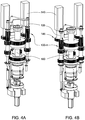
- the extent of gear profile 130-m along shaft 135 may be sufficient to engage motor gear 145 when drive gears 130 is both in an upper position (shown in Figures 4A and 5 ) and in a lower position (shown in Figures 4B and 6 ).
- Motor 140 may turn motor gear 145, which engages gear profile 130-m, thereby turning drive gears 130.
- drive gears 130 may engage drive stem 180.
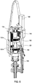
- Gear profile 130-s may engage drive stem gear 185 when drive gears 130 is in an upper position (shown in Figure 5 ).
- drive gears 130 may turn gear profile 130-s, which engages drive stem gear 185, thereby turning drive stem 180.
- gear profile 130-t is not engaged with torque shaft gear 195.
- drive gears 130 may engage torque shaft 190.
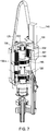
- Gear profile 130-t may engage torque shaft gear 195 when drive gears 130 is in a lower position (shown in Figures 4 and 6 ).
- drive gears 130 may turn gear profile 130-t, which engages torque shaft gear 195, thereby turning torque shaft 190.
- gear profile 130-s is not engaged with drive stem gear 185.
- Drive gears 130 may shift between a first position, wherein drive gears 130 engage - directly or indirectly - with drive stem 180, and a second position, wherein drive gears 130 engage - directly or indirectly - with torque shaft 190.
- a shift actuator 231 may cause drive gears 130 to move vertically, thereby shifting between the first position ( e.g. , the upper position of Figure 5 ) and the second position ( e.g. , the lower position of Figures 4 and 6 ).
- shift actuator 231 is a linear actuator. Shift actuator 231 extends and retracts shift arm 232, thereby causing shift plate 233 to translate vertically.
- shift plate 233 connects to two drive gear shafts 135. Vertical translation of shift plate 233 causes each of the drive gear shafts 135 to move vertically, thereby shifting drive gears 130 between the first position and the second position.
- drive gears 130 may shift among more than two positions. For example, shifting drive gears 130 to a third position (not shown) may disengage drive gears 130 from motors 140. It should be appreciated that other shift actuator 231 types and/or configurations may be considered to accommodate manufacturing and operational conditions.
- Drive unit 110 may be coupled to tool adapter 150 in order to transfer bi-directional torque, load, power, data, and/or signals between the top drive and the tool. Coupling of drive unit 110 to tool adapter 150 may proceed as a multi-step process. In one embodiment, as illustrated in Figures 8A-8B , the coupling begins with axial load coupling between drive stem 180 and tool stem 160. When drive gears 130 engage drive stem 180 ( e.g. , drive gears 130 in the upper position shown in Figure 5 ), torque may be provided to make up or break out the connection between tool stem 160 and drive stem 180.
- couplings 170 include threaded couplings 171 between tool stem 160 and drive stem 180
- torque of drive stem 180 may cause threading (or unthreading, depending on direction) between tool stem 160 and drive stem 180.
- couplings 170 may include a rotary shouldered connection, such as an 8 5/8" API regular, NC77 connection.
- the drive stem 180 may have RH male threading, while the tool stem 160 may have RH female threading.
- axial load may be transferred between the top drive and the tool.
- central bore 165 may provide fluid communication between the top drive and the tool.
- torque in the direction of the threaded couplings 171 may also be transferred between the top drive and the tool.
- torque may be transferred from the motors 140 through motor gears 145 to the gear profiles 130-m, to the shafts 135, to the gear profiles 130-s, through drive stem gears to the drive stem 180, through the threaded couplings 171, to the tool stem 160, and to the tool string 2.
- coupling drive stem 180 to tool stem 160 may be facilitated with various sensors, actuators, couplers, and/or adapters.
- tool stem 160 may be positioned for coupling and supported while coupling by a positioning adapter 261.
- the positioning adapter 261 may include a clamp 262 ( e.g. , an articulating claim), one or more actuators 263 ( e.g. , thread compensation cylinders), one or more supports 264 ( e.g., a torque reaction post), and one or more hinges 266.
- the supports 264 and hinges 266 may fix positioning adapter 261 to housing 120.
- the actuators 263 may cause the hinges 266 and supports 264 to move clamp 262 into position to receive tool stem 160.
- an actuator 263-a may rotate support 264-s between a vertical position, wherein clamp 262 encircles the central axis of the top drive system ( Figure 9A ), and a tilted position, wherein clamp 262 is away from the central axis ( Figure 9B ).
- Clamp 262 may firmly grip tool stem 160 while moving tool stem 160 into position to couple with drive stem 180.
- tool stem 160 may have a clamp profile 267 ( Figure 9D ) that provides additional grip between clamp 262 and tool stem 160.
- a pair of actuators 263-b move clamp 262 along the length of support 264-s.
- Clamp 262 may thereby move tool stem 160 vertically when coupling (or decoupling) with drive stem 180. While coupling - for example while drive gears 130 engage and rotate drive stem 180, thereby threading threaded couplings 171 - clamp 262 may prevent or reduce rotation of tool stem 160. Clamp 262 may continue to position and/or support tool stem 160 during bi-directional torque coupling. Clamp 262 may release tool stem 160, for example after load coupling and/or after bi-directional torque coupling, to allow rotation during drilling operations. It should be appreciated that other sensors, actuators, and/or adapters types and/or configurations may be considered to accommodate manufacturing and operational conditions.
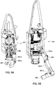
- Coupling of drive unit 110 to tool adapter 150 may proceed with bi-directional torque coupling between torque shaft 190 and tool stem 160, as illustrated in Figures 8B-8C .
- the drive stem 180 may extend through a central bore of torque shaft 190.
- Torque shaft 190 may move vertically relative to drive stem 180. While tool stem 160 is coupling to drive stem 180, as shown in Figures 8A-8B , torque shaft 190 may be in a raised position (relative to drive stem 180; Figure 8B ). Torque shaft 190 may then move to a lowered position (relative to drive stem 180; Figure 8C ) to engage tool stem 160, thereby transferring torque.
- couplings 170 may include key couplings 172 ( Figures 9C-9D ) for conveying torque between torque shaft 190 and tool stem 160.
- key couplings 172 may be disposed on an interior surface of torque shaft 190
- complementary key couplings 172 may be disposed on an exterior surface of tool stem 160.
- the key couplings 172 may have guiding chamfers. It should be appreciated that other torque coupling types and/or configurations may be considered to accommodate manufacturing and operational conditions.
- Clamp 262 may continue to position and/or support tool stem 160 during bi-directional torque coupling. Once torque shaft 190 has moved to a lowered position and coupled to tool stem 160, as shown in Figure 8C , bi-directional torque may be transferred between the top drive and the tool.
- drive gears 130 may engage torque shaft 190 (e.g. , drive gears 130 in a lower position as shown in Figures 4 and 6 ), thereby providing torque to tool stem 160 during drilling operations.
- torque may be transferred from the motors 140 through the motor gears 145 to the gear profiles 130-m, to the shafts 135, to the gear profiles 130-t, through the torque shaft gears 195 to the torque shaft 190, through the key couplings 172, to the tool stem 160, and to the tool string 2.
- the torque transfer path may thereby bypass threaded couplings 171.
- coupling torque shaft 190 to tool stem 160 may be facilitated with various sensors, actuators, couplers, and/or adapters.
- torque shaft 190 may be first oriented relative to tool stem 160 so that key couplings 172 align.
- a sensor 291 e.g. , an optical sensor; Figure 9C
- the sensor 291 may be configured to detect a marker 292 (e.g., a reflector; Figure 9D ) disposed at the top of tool stem 160.
- Torque shaft 190 may be rotated relative to tool stem 160 until sensor 291 detects alignment with marker 292.
- Clamp 262 may continue to position and/or support tool stem 160 during bi-directional torque coupling.
- an alignment motor 293 ( Figure 8B ), disposed in housing 120, may rotate torque shaft 190 relative to tool stem 160.
- alignment motor 293 may have an alignment gear 294 that is configured to engage with torque shaft gear 195 while torque shaft 190 is in the raised position. Alignment motor 293 may thereby rotate torque shaft 190 relative to tool stem 160 until sensor 291 detects alignment with marker 292.
- tool stem 160 may be rotated relative to torque shaft 190.
- motors 140 may engage drive gears 130, thereby causing tool stem 180 to rotate. Threaded couplings 171 may then transfer the rotation to tool stem 160.
- both alignment motor 293 may rotate torque shaft 190 relative to tool stem 160, and motors 140 may rotate tool stem 160 relative to torque shaft 190 until sensor 291 detects alignment with marker 292.
- multiple markers 292 may be utilized.
- torque shaft 190 may be appropriately oriented in two or more orientations relative to tool stem 160. Sensor 291 need only detect alignment with the first marker 292 to identify appropriate orientation of torque shaft 190 relative to tool stem 160.
- torque shaft 190 may be facilitated with various sensors, actuators, couplers, and/or adapters.
- One or more support actuators 296 e.g. , hydraulic cylinders; Figure 8A
- Torque shaft 190 may be connected to support plate 297 to couple vertical translational motion, but to allow free rotation therebetween.
- support actuators 296 raises (or lowers) support plate 297
- torque shaft 190 may be thereby raised (or lowered).
- alignment motor 293 rotates torque shaft 190, support plate 297 remains fixed relative to housing 120.
- Couplings 170 may include one or more hydraulic, pneumatic, electrical, or optical couplings, providing fluid, electrical, optical, signal, data, and/or power communication between the drive unit 110 and the tool adapter 150.
- couplings 170 may include a swivel 273 (e.g., a hydraulic swivel), lines 274, and connectors 276 ( e.g., quick-connects). Swivel 273 may be disposed co-axially with torque shaft 190. Swivel 273 may encircle torque shaft 190.
- swivel 273 may be fixed relative to housing 120 while allowing rotation between swivel 273 and torque shaft 190. In some embodiments, swivel 273 may be fixed relative to torque shaft 190 while allowing rotation between swivel 273 and housing 120. In some embodiments, swivel 273 may be free to rotate both relative to torque shaft 190 and housing 120. Lines 274 may extend from swivel 273 to the base of torque shaft 190. Connectors 276 at the base of torque shaft 190 may receive lines 274. Mating connectors 276 may be disposed at the top of tool stem 160.
- a hydraulic coupling between torque shaft 190 and tool stem 160 may include a hydraulic path through swivel 273 and a line 274 to connector 276 at the base of torque shaft 190.
- connector 276 at the base of torque shaft 190 mates with connector 276 at the top of tool stem 160.
- additional hydraulic, pneumatic, electrical, or optical couplings 170 between torque shaft 190 and tool stem 160 may be connected.
- the fluid, electrical, optical, signal, data, and/or power communication may be extended to the tool string 2 via lines 277 along tool stem 160 ( Figure 9D ).
- the coupling of torque shaft 190 to tool stem 160 may be further facilitated with various sensors, actuators, couplers, and/or adapters.
- the torque coupling may be facilitated with a locking adapter having related sensor(s) and actuator(s).
- a locking adapter may hold torque shaft 190 in the lower position (coupled to tool stem 160).
- the locking adapter may be fixed to housing 120.
- the locking adapter may be proximate alignment motor 293.
- a locking sensor may detect when torque shaft 190 has coupled with tool stem 160.
- a locking actuator may respond to the locking sensor by actuating the locking adapter.
- the locking adapter may resist vertical motion of the torque shaft 190 which could compromise the torque coupling between the torque shaft 190 and the tool stem 160.
- the locking adapter may permit rotation between the torque shaft 190 and the housing 120.
- the actuators may be, for example, worm drives, hydraulic cylinders, compensation cylinders, etc.
- the actuators may be hydraulically, electrically, and/or manually controlled.
- multiple control mechanism may be utilized to provide redundancy.
- One or more sensors may be used to monitor relative positions of the components of the top drive system 100.
- the sensors may be position sensors, rotation sensors, pressure sensors, optical sensors, magnetic sensors, etc.
- stop surfaces may be used in conjunction with or in lieu of sensors to identify when components are appropriately positioned and or oriented ( e.g.
- optical guides may be utilized to identify or confirm when components are appropriately positioned and or oriented.
- guide elements e.g. , pins and holes, chamfers, etc.
- Bearings and seals may be disposed between components to provide support, cushioning, rotational freedom, and/or fluid management.
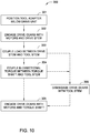
- a method 300 of coupling drive unit 110 with tool adapter 150 is illustrated in Figure 10 .
- the method begins at step 301 wherein the tool adapter 150 is positioned below the drive unit 110.
- a positioning adapter 261 may be used to position a tool stem 160 of the tool adapter 150 below the drive unit 110.
- the tool stem 160 may be positioned so that threaded connections 171 between the tool stem 160 and a drive stem 180 of the drive unit 110 are readied for threading.
- the method 300 continues at step 302, wherein drive gears 130 of the drive unit 110 engage with motors 140 of the drive unit 110.
- drive gears 130 also engage with the drive stem 180.
- Motors 140 transfer torque to drive gears 130, thereby transferring torque to drive stem 180.
- drive gears 130 may be in an upper position, thereby engaging drive stem gear 185.
- Torque shaft 190 may also be in a raised position.
- step 303 rotation of drive stem 180 relative to tool stem 160 causes threading of threaded connections 171 between the tool stem 160 and the drive stem 180, coupling load therebetween. It should be appreciated that, at the completion of step 303, torque in the direction of the threaded couplings 171 is also coupled between the tool stem 160 and the drive stem 180.
- step 304 wherein a bi-directional torque coupling is established between torque shaft 190 and tool stem 160. For example, key couplings 172 on torque shaft 190 may be mated with key couplings 172 on tool stem 160.
- a support actuator 296 may move support plate 297 from the raised position to a lowered position, thereby moving torque shaft 190 from a raised position to a lowered position, thereby mating key couplings 172.
- additional couplings 170 also may be connected, including one or more hydraulic, pneumatic, electrical, or optical couplings, thereby providing fluid, electrical, optical, signal, data, and/or power communication between the drive unit 110 and the tool adapter 150.
- the method goes further at step 305 to transfer bi-directional torque, wherein drive gears 130 of the drive unit 110 engage with motors 140 of the drive unit 110.
- drive gears 130 also engage with the torque shaft 190.
- shift actuator 231 moves drive gears 130 from an upper position to a lower position to engage the drive gears 130 with the torque shaft 190.
- Motors 140 transfer torque to torque shaft 190, thereby transferring bi-directional torque to tool stem 160.
- drive gears 130 may be in a lower position, thereby engaging torque shaft gear 195.
- step 306 drive gears 130 disengage with tool stem 180. In some embodiments, disengaging the drive gears 130 with the tool stem 180 at step 306 occurs prior to coupling of bi-directional torque at step 304.
- disengaging the drive gears 130 with the tool stem 180 at step 306 occurs subsequent to coupling of bi-directional torque at step 304.
- shift actuator 231 moves drive gears 130 from an upper position to a lower position to disengage the drive gears 130 with the tool stem 180. It should be appreciated that drive unit 110 may be de-coupled from tool adapter 150 by reversing the steps of method 300.
- a drive unit of a top drive system includes a first, second, and third drive gears, wherein the first, second, and third drive gears are operationally coupled; a motor engagable with the first drive gear; a drive stem having a load coupling and engagable with the second drive gear; and a torque shaft having a torque coupling and engagable with the third drive gear, wherein the drive stem cannot engage with the second drive gear when the torque shaft is engaged with the third drive gear, and vice versa.
- the first, second, and third drive gears are axially aligned on a common shaft.
- the load coupling is a threaded coupling.
- the torque coupling is a key coupling.
- the drive stem extends through a central bore of the torque shaft.
- the drive unit also includes a swivel co-axial with the torque shaft.
- the swivel is a hydraulic swivel.
- the drive unit also includes a shift actuator coupled to the first, second, and third drive gears, wherein the shift actuator is configured to move the first, second, and third drive gears between: an upper position wherein the second drive gear engages with the drive stem, and a lower position wherein the third drive gear engages with the torque shaft.
- the drive unit also includes a support actuator configured to move the torque shaft between: a raised position wherein the torque shaft is engaged with an alignment gear, and a lowered position wherein the torque shaft is disengaged with the alignment gear.
- the drive unit also includes a positioning adapter configured to move between a vertical position and a tilted position relative to the drive unit.
- the top drive system also includes a tool adapter having a complementary load coupling to the load coupling of the drive stem, and a complementary torque coupling to the torque coupling of the torque shaft.
- the drive unit further comprises a support actuator configured to move the torque shaft between: a raised position wherein the torque shaft is engaged with an alignment gear, and a lowered position wherein the torque shaft is coupled to the tool adapter.
- the drive unit further comprises a positioning adapter having a clamp; the tool adapter comprises a tool stem having a clamp profile; and the clamp is configured to engage the clamp profile to move the tool stem into position to couple with the drive stem.
- the top drive system also includes at least one coupling between the drive unit and the tool adapter selected from a group consisting of: threaded couplings, hydraulic couplings, pneumatic couplings, electronic couplings, fiber optic couplings, power couplings, data couplings, signal couplings, bi-directional torque couplings, axial load couplings, power couplings, data couplings, and signal couplings.
- at least one coupling between the drive unit and the tool adapter selected from a group consisting of: threaded couplings, hydraulic couplings, pneumatic couplings, electronic couplings, fiber optic couplings, power couplings, data couplings, signal couplings, bi-directional torque couplings, axial load couplings, power couplings, data couplings, and signal couplings.
- a method of coupling a drive unit to a tool adapter includes positioning the tool adapter below the drive unit; engaging a first drive gear with a motor of the drive unit while engaging a second drive gear with a drive stem of the drive unit; coupling a load between the drive stem and a tool stem of the tool adapter; and coupling a torque between a torque shaft of the drive unit and the tool stem.
- the method also includes engaging the first drive gear with the motor while engaging a third drive gear with the torque shaft.
- the method also includes, after coupling the load between the drive stem and the tool stem, and before engaging the third drive gear with the torque shaft, disengaging the second drive gear with the drive stem.
- the disengaging the second drive gear with the drive stem follows the coupling the torque between the torque shaft of the drive unit and the tool stem.
- the method also includes moving the first and second drive gears from an upper position to a lower position to disengage the motor from the drive stem.
- the method also includes moving the torque shaft from a raised position to a lowered position to couple the torque.
- the method also includes moving a positioning adapter from a tilted position to a vertical position to position the tool adapter below the drive unit.
- coupling the load comprises rotating the drive stem relative to the tool stem in a first direction.
- the method also includes rotating the tool stem in the first direction.
- rotating the tool stem in the first direction comprises engaging the first drive gear with the motor while engaging a third drive gear with the torque shaft.
- coupling the torque comprises lowering the torque shaft relative to the tool stem.
- the method also includes aligning the torque shaft with the tool stem before lowering the torque shaft relative to the tool stem.
- the method also includes forming a coupling between the drive unit and the tool adapter, wherein the coupling is selected from a group consisting of: threaded couplings, hydraulic couplings, pneumatic couplings, electronic couplings, fiber optic couplings, power couplings, data couplings, signal couplings, bi-directional torque couplings, axial load couplings, power couplings, data couplings, and signal couplings.
- the coupling is selected from a group consisting of: threaded couplings, hydraulic couplings, pneumatic couplings, electronic couplings, fiber optic couplings, power couplings, data couplings, signal couplings, bi-directional torque couplings, axial load couplings, power couplings, data couplings, and signal couplings.
- a top drive system includes a drive unit; a tool adapter having a tool stem; a first torque path including: a motor of the drive unit; a first pair of operationally coupled drive gears of the drive unit; a drive stem of the drive unit; a threaded connection between the drive stem and the tool stem; and a second torque path including: the motor; a second pair of operationally coupled drive gears of the drive unit; a torque shaft of the drive unit; and a torque coupling between the torque shaft and the tool stem.
- the second torque path bypasses the threaded connection between the drive stem and the tool stem.
- the first pair of drive gears and the second pair of drive gears share a common gear.
Landscapes
- Engineering & Computer Science (AREA)
- Life Sciences & Earth Sciences (AREA)
- Geology (AREA)
- Mining & Mineral Resources (AREA)
- Physics & Mathematics (AREA)
- Environmental & Geological Engineering (AREA)
- Fluid Mechanics (AREA)
- General Life Sciences & Earth Sciences (AREA)
- Geochemistry & Mineralogy (AREA)
- Mechanical Engineering (AREA)
- Earth Drilling (AREA)
- Gear Transmission (AREA)
Claims (15)
- Unité d'entraînement (110) d'un système d'entraînement par le haut (100), comprenant :des premier (130-m), deuxième (130-s) et troisième (130-t) engrenages d'entraînement, dans laquelle les premier, deuxième et troisième engrenages d'entraînement sont accouplés en service ;un moteur (140) pouvant s'engager avec le premier engrenage d'entraînement ;une tige d'entraînement (180) comportant un accouplement de charge et pouvant s'engager avec le deuxième engrenage d'entraînement ; etun arbre de couple (190) comportant un accouplement de couple et pouvant s'engager avec le troisième engrenage d'entraînement, les engrenages d'entraînement se déplaçant entre une première position et une deuxième position, la tige d'entraînement étant dégagée du deuxième engrenage d'entraînement et l'arbre de couple étant engagé avec le troisième engrenage d'entraînement dans la première position, et la tige d'entraînement étant engagée avec le deuxième engrenage d'entraînement et l'arbre de couple étant dégagé du troisième engrenage d'entraînement dans la deuxième position.
- Unité d'entraînement selon la revendication 1, dans laquelle les premier, deuxième, et troisième engrenages d'entraînement sont alignés axialement sur un arbre commun (135).
- Unité d'entraînement selon les revendications 1 ou 2, dans laquelle l'accouplement de charge est un accouplement fileté, l'accouplement de couple étant un accouplement à clé.
- Unité d'entraînement selon les revendications 1, 2 ou 3, comprenant en outre un actionneur de changement de mode (231) accouplé aux premier, deuxième et troisième engrenages d'entraînement, l'actionneur de changement de mode étant configuré pour déplacer les premier, deuxième et troisième engrenages d'entraînement entre :la deuxième position, dans laquelle le deuxième engrenage d'entraînement s'engage avec la tige d'entraînement, etla première position dans laquelle le troisième engrenage d'entraînement s'engage avec l'arbre de couple.
- Unité d'entraînement selon l'une quelconque des revendications précédentes, comprenant en outre un actionneur de support (296) configuré pour déplacer l'arbre de couple entre :une position surélevée, dans laquelle l'arbre de couple est engagé avec un engrenage d'alignement ; etune position abaissée, dans laquelle l'arbre de couple est dégagé de l'engrenage d'alignement.
- Système d'entraînement par le haut (100) selon l'une quelconque des revendications 1 à 4, comprenant en outre un adaptateur d'outil (150) comportant un accouplement de charge complémentaire de l'accouplement de charge de la tige d'entraînement, et un accouplement de charge complémentaire de l'accouplement de couple de l'arbre de couple ; et
et dans lequel l'unité d'entraînement comprend en outre optionnellement un actionneur de support (296) configuré pour déplacer l'arbre de couple entre une position surélevée, dans laquelle l'arbre de couple est engagé avec un engrenage d'alignement, et une position abaissée, dans laquelle l'arbre de couple est accouplé à l'adaptateur d'outil. - Système d'entraînement par le haut selon la revendication 6, dans lequel :l'unité d'entraînement comprend en outre un adaptateur de positionnement (261) comportant une pince (262) ;l'adaptateur d'outil comprend une tige d'outil (160) ayant un profil de pince (267) ; etla pince est configurée pour s'engager avec le profil de pince pour déplacer la tige d'outil dans sa position en vue de l'accouplement à la tige d'outil.
- Système d'entraînement par le haut selon l'une quelconque des revendications 1 à 7, comprenant :l'adaptateur d'outil comportant une tige d'outil ;un premier trajet de couple, incluant :le moteur ;les premier et deuxième engrenages d'entraînement ;la tige d'entraînement ;une connexion filetée entre la tige d'entraînement et la tige d'outil ; etun deuxième trajet de couple, incluant :le moteur ;les premier et troisième engrenages d'entraînement ;l'arbre de couple ; etl'accouplement de couple entre l'arbre de couple et la tige d'outil.
- Système d'entraînement par le haut selon la revendication 8, dans lequel le deuxième trajet de couple contourne la connexion filetée entre la tige d'entraînement et la tige d'outil.
- Procédé (300) d'accouplement d'une unité d'entraînement (110) d'un système d'entraînement par le haut (100) à un adaptateur d'outil (150) comprenant les étapes ci-dessous :positionnement de l'adaptateur d'outil au-dessous de l'unité d'entraînement (301) ;engagement d'un premier engrenage d'entraînement (130-m) avec un moteur (140) de l'unité d'entraînement, tout en engageant un deuxième engrenage d'entraînement (130-s) avec une tige d'entraînement (180) de l'unité d'entraînement (302) ;accouplement d'une charge entre la tige d'entraînement et une tige d'outil (160) de l'adaptateur outil (303) ; etaccouplement d'un couple entre un arbre de couple (190) de l'unité d'entraînement et la tige d'outil (304).
- Procédé selon la revendication 10, comprenant en outre l'étape d'engagement du premier engrenage d'entraînement avec le moteur tout en engageant un troisième engrenage d'entraînement (130-t) avec l'arbre de couple.
- Procédé selon la revendication 11, comprenant en outre, après l'étape d'accouplement de la charge entre la tige d'entraînement et la tige d'outil, et avant l'étape d'engagement du troisième engrenage d'entraînement avec l'arbre de couple, l'étape de dégagement du deuxième engrenage d'entraînement de la tige d'entraînement ;
et dans lequel, l'étape de dégagement du deuxième engrenage d'entraînement de la tige d'entraînement suit l'étape d'accouplement du couple entre l'arbre de couple de l'unité d'entraînement et la tige d'outil. - Procédé selon les revendications 10, 11 ou 12, comprenant en outre l'étape de déplacement des premier et deuxième engrenages d'entraînement d'une position supérieure vers une position inférieure afin de dégager le moteur de la tige d'entraînement, et/ou comprenant en outre l'étape de déplacement de l'arbre de couple d'une position surélevée vers une position abaissée afin d'accoupler le couple.
- Procédé selon l'une quelconque des revendications 10 à 13, dans lequel l'étape d'accouplement de la charge comprend l'étape de rotation de la tige d'entraînement par apport à la tige d'outil dans une première direction, le procédé comprenant en outre l'étape de rotation de la tige d'outil dans la première direction ;
et dans lequel l'étape de rotation de la tige d'outil dans la première direction comprend optionnellement l'étape d'engagement du premier engrenage d'entraînement avec le moteur, tout en engageant un troisième engrenage d'entraînement avec l'arbre de couple. - Procédé selon l'une quelconque des revendications 10 à 14 dans lequel l'étape d'accouplement du couple comprend l'étape d'abaissement de l'arbre de couple par rapport à la tige d'outil.
Applications Claiming Priority (1)
| Application Number | Priority Date | Filing Date | Title |
|---|---|---|---|
| US15/447,881 US10132118B2 (en) | 2017-03-02 | 2017-03-02 | Dual torque transfer for top drive system |
Publications (2)
| Publication Number | Publication Date |
|---|---|
| EP3369887A1 EP3369887A1 (fr) | 2018-09-05 |
| EP3369887B1 true EP3369887B1 (fr) | 2020-04-22 |
Family
ID=61557131
Family Applications (1)
| Application Number | Title | Priority Date | Filing Date |
|---|---|---|---|
| EP18159595.0A Active EP3369887B1 (fr) | 2017-03-02 | 2018-03-01 | Transfert de couple double pour système d'entraînement par le haut |
Country Status (3)
| Country | Link |
|---|---|
| US (1) | US10132118B2 (fr) |
| EP (1) | EP3369887B1 (fr) |
| CA (1) | CA2996890C (fr) |
Families Citing this family (1)
| Publication number | Priority date | Publication date | Assignee | Title |
|---|---|---|---|---|
| CN110905398B (zh) * | 2019-12-06 | 2020-09-08 | 中国地质大学(北京) | 一种煤层气开采用抽采口钻设装置 |
Family Cites Families (25)
| Publication number | Priority date | Publication date | Assignee | Title |
|---|---|---|---|---|
| US4497224A (en) | 1983-08-11 | 1985-02-05 | Norton Christensen, Inc. | Apparatus for making and breaking screw couplings |
| US5433279A (en) | 1993-07-20 | 1995-07-18 | Tessari; Robert M. | Portable top drive assembly |
| GB9815809D0 (en) | 1998-07-22 | 1998-09-16 | Appleton Robert P | Casing running tool |
| US20120175130A1 (en) | 1998-12-24 | 2012-07-12 | Bernd-Georg Pietras | Apparatus and methods for facilitating the connection of tubulars using a top drive |
| US7107875B2 (en) | 2000-03-14 | 2006-09-19 | Weatherford/Lamb, Inc. | Methods and apparatus for connecting tubulars while drilling |
| US6908121B2 (en) | 2001-10-22 | 2005-06-21 | Weatherford/Lamb, Inc. | Locking arrangement for a threaded connector |
| WO2004011812A2 (fr) | 2002-07-30 | 2004-02-05 | Comprehensive Power, Inc. | Systeme de commande de verin pour dispositifs hydrauliques |
| US7874352B2 (en) | 2003-03-05 | 2011-01-25 | Weatherford/Lamb, Inc. | Apparatus for gripping a tubular on a drilling rig |
| US7320374B2 (en) | 2004-06-07 | 2008-01-22 | Varco I/P, Inc. | Wellbore top drive systems |
| US7188686B2 (en) | 2004-06-07 | 2007-03-13 | Varco I/P, Inc. | Top drive systems |
| CA2586914C (fr) | 2004-11-08 | 2013-02-19 | Tesco Corporation | Multiplicateur de couple pour materiel tubulaire de trou de forage |
| US8215196B2 (en) | 2007-04-27 | 2012-07-10 | Mccoy Corporation | Tong gear shift system |
| AU2014215938B2 (en) | 2007-12-12 | 2016-09-29 | Weatherford Technology Holdings, Llc | Top drive system |
| DK2450524T3 (en) | 2007-12-12 | 2015-09-28 | Weatherford Technology Holdings Llc | Upper drive |
| US9297223B2 (en) | 2008-02-12 | 2016-03-29 | Warrior Rig Ltd. | Top drive with slewing power transmission |
| WO2009135220A2 (fr) | 2008-05-02 | 2009-11-05 | Weatherford/Lamb, Inc. | Outil de remplissage et de mise en circulation et vanne de récupérateur de boue |
| US7971637B2 (en) | 2009-02-26 | 2011-07-05 | Devin International, Inc. | Dual mini well surface control system |
| US8505984B2 (en) | 2011-09-02 | 2013-08-13 | Kris Henderson | Connection assembly for tubular goods |
| US9206851B2 (en) | 2012-08-16 | 2015-12-08 | The Charles Machine Works, Inc. | Horizontal directional drill pipe drive connection with locking feature |
| CA2830860C (fr) * | 2012-10-25 | 2020-10-27 | Warrior Rig Ltd. | Entrainement de tubage integre |
| MX393861B (es) | 2015-01-26 | 2025-03-24 | Weatherford Tech Holdings Llc | Sistema modular de propulsion superior. |
| US10626683B2 (en) | 2015-08-11 | 2020-04-21 | Weatherford Technology Holdings, Llc | Tool identification |
| US10323484B2 (en) | 2015-09-04 | 2019-06-18 | Weatherford Technology Holdings, Llc | Combined multi-coupler for a top drive and a method for using the same for constructing a wellbore |
| WO2017044482A1 (fr) | 2015-09-08 | 2017-03-16 | Weatherford Technology Holdings, Llc | Groupe électrogène pour unité d'entraînement supérieure |
| US10590744B2 (en) | 2015-09-10 | 2020-03-17 | Weatherford Technology Holdings, Llc | Modular connection system for top drive |
-
2017
- 2017-03-02 US US15/447,881 patent/US10132118B2/en active Active
-
2018
- 2018-02-28 CA CA2996890A patent/CA2996890C/fr active Active
- 2018-03-01 EP EP18159595.0A patent/EP3369887B1/fr active Active
Non-Patent Citations (1)
| Title |
|---|
| None * |
Also Published As
| Publication number | Publication date |
|---|---|
| US10132118B2 (en) | 2018-11-20 |
| CA2996890A1 (fr) | 2018-09-02 |
| CA2996890C (fr) | 2022-03-08 |
| US20180252041A1 (en) | 2018-09-06 |
| EP3369887A1 (fr) | 2018-09-05 |
Similar Documents
| Publication | Publication Date | Title |
|---|---|---|
| EP3366879B1 (fr) | Coupleur d'outil comportant un procédé de couplage rotatif pour un entraînement supérieur | |
| AU2018247252B2 (en) | Tool coupler with data and signal transfer methods for top drive | |
| EP3379018B1 (fr) | Coupleur d'outil comportant des éléments de couplage coulissant pour mécanisme d'entraînement supérieur | |
| EP3404196B1 (fr) | Coupleur d'outil à connexion filetée pour un entraînement supérieur | |
| EP3369887B1 (fr) | Transfert de couple double pour système d'entraînement par le haut | |
| EP3665357B1 (fr) | Système d'accouplement d'outil de fond de trou | |
| EP3655618B1 (fr) | Coupleur d'outil destiné à être utilisé avec un entraînement supérieur | |
| US10480247B2 (en) | Combined multi-coupler with rotating fixations for top drive |
Legal Events
| Date | Code | Title | Description |
|---|---|---|---|
| PUAI | Public reference made under article 153(3) epc to a published international application that has entered the european phase |
Free format text: ORIGINAL CODE: 0009012 |
|
| STAA | Information on the status of an ep patent application or granted ep patent |
Free format text: STATUS: THE APPLICATION HAS BEEN PUBLISHED |
|
| AK | Designated contracting states |
Kind code of ref document: A1 Designated state(s): AL AT BE BG CH CY CZ DE DK EE ES FI FR GB GR HR HU IE IS IT LI LT LU LV MC MK MT NL NO PL PT RO RS SE SI SK SM TR |
|
| AX | Request for extension of the european patent |
Extension state: BA ME |
|
| STAA | Information on the status of an ep patent application or granted ep patent |
Free format text: STATUS: REQUEST FOR EXAMINATION WAS MADE |
|
| 17P | Request for examination filed |
Effective date: 20181105 |
|
| RBV | Designated contracting states (corrected) |
Designated state(s): AL AT BE BG CH CY CZ DE DK EE ES FI FR GB GR HR HU IE IS IT LI LT LU LV MC MK MT NL NO PL PT RO RS SE SI SK SM TR |
|
| GRAP | Despatch of communication of intention to grant a patent |
Free format text: ORIGINAL CODE: EPIDOSNIGR1 |
|
| STAA | Information on the status of an ep patent application or granted ep patent |
Free format text: STATUS: GRANT OF PATENT IS INTENDED |
|
| INTG | Intention to grant announced |
Effective date: 20191015 |
|
| GRAS | Grant fee paid |
Free format text: ORIGINAL CODE: EPIDOSNIGR3 |
|
| GRAA | (expected) grant |
Free format text: ORIGINAL CODE: 0009210 |
|
| STAA | Information on the status of an ep patent application or granted ep patent |
Free format text: STATUS: THE PATENT HAS BEEN GRANTED |
|
| AK | Designated contracting states |
Kind code of ref document: B1 Designated state(s): AL AT BE BG CH CY CZ DE DK EE ES FI FR GB GR HR HU IE IS IT LI LT LU LV MC MK MT NL NO PL PT RO RS SE SI SK SM TR |
|
| REG | Reference to a national code |
Ref country code: CH Ref legal event code: EP |
|
| REG | Reference to a national code |
Ref country code: IE Ref legal event code: FG4D |
|
| REG | Reference to a national code |
Ref country code: DE Ref legal event code: R096 Ref document number: 602018003866 Country of ref document: DE |
|
| REG | Reference to a national code |
Ref country code: AT Ref legal event code: REF Ref document number: 1260290 Country of ref document: AT Kind code of ref document: T Effective date: 20200515 |
|
| REG | Reference to a national code |
Ref country code: GB Ref legal event code: 732E Free format text: REGISTERED BETWEEN 20200813 AND 20200819 |
|
| REG | Reference to a national code |
Ref country code: LT Ref legal event code: MG4D |
|
| REG | Reference to a national code |
Ref country code: NL Ref legal event code: MP Effective date: 20200422 |
|
| PG25 | Lapsed in a contracting state [announced via postgrant information from national office to epo] |
Ref country code: SE Free format text: LAPSE BECAUSE OF FAILURE TO SUBMIT A TRANSLATION OF THE DESCRIPTION OR TO PAY THE FEE WITHIN THE PRESCRIBED TIME-LIMIT Effective date: 20200422 Ref country code: NL Free format text: LAPSE BECAUSE OF FAILURE TO SUBMIT A TRANSLATION OF THE DESCRIPTION OR TO PAY THE FEE WITHIN THE PRESCRIBED TIME-LIMIT Effective date: 20200422 Ref country code: PT Free format text: LAPSE BECAUSE OF FAILURE TO SUBMIT A TRANSLATION OF THE DESCRIPTION OR TO PAY THE FEE WITHIN THE PRESCRIBED TIME-LIMIT Effective date: 20200824 Ref country code: LT Free format text: LAPSE BECAUSE OF FAILURE TO SUBMIT A TRANSLATION OF THE DESCRIPTION OR TO PAY THE FEE WITHIN THE PRESCRIBED TIME-LIMIT Effective date: 20200422 Ref country code: IS Free format text: LAPSE BECAUSE OF FAILURE TO SUBMIT A TRANSLATION OF THE DESCRIPTION OR TO PAY THE FEE WITHIN THE PRESCRIBED TIME-LIMIT Effective date: 20200822 Ref country code: NO Free format text: LAPSE BECAUSE OF FAILURE TO SUBMIT A TRANSLATION OF THE DESCRIPTION OR TO PAY THE FEE WITHIN THE PRESCRIBED TIME-LIMIT Effective date: 20200722 Ref country code: GR Free format text: LAPSE BECAUSE OF FAILURE TO SUBMIT A TRANSLATION OF THE DESCRIPTION OR TO PAY THE FEE WITHIN THE PRESCRIBED TIME-LIMIT Effective date: 20200723 Ref country code: FI Free format text: LAPSE BECAUSE OF FAILURE TO SUBMIT A TRANSLATION OF THE DESCRIPTION OR TO PAY THE FEE WITHIN THE PRESCRIBED TIME-LIMIT Effective date: 20200422 |
|
| REG | Reference to a national code |
Ref country code: AT Ref legal event code: MK05 Ref document number: 1260290 Country of ref document: AT Kind code of ref document: T Effective date: 20200422 |
|
| PG25 | Lapsed in a contracting state [announced via postgrant information from national office to epo] |
Ref country code: LV Free format text: LAPSE BECAUSE OF FAILURE TO SUBMIT A TRANSLATION OF THE DESCRIPTION OR TO PAY THE FEE WITHIN THE PRESCRIBED TIME-LIMIT Effective date: 20200422 Ref country code: HR Free format text: LAPSE BECAUSE OF FAILURE TO SUBMIT A TRANSLATION OF THE DESCRIPTION OR TO PAY THE FEE WITHIN THE PRESCRIBED TIME-LIMIT Effective date: 20200422 Ref country code: BG Free format text: LAPSE BECAUSE OF FAILURE TO SUBMIT A TRANSLATION OF THE DESCRIPTION OR TO PAY THE FEE WITHIN THE PRESCRIBED TIME-LIMIT Effective date: 20200722 Ref country code: RS Free format text: LAPSE BECAUSE OF FAILURE TO SUBMIT A TRANSLATION OF THE DESCRIPTION OR TO PAY THE FEE WITHIN THE PRESCRIBED TIME-LIMIT Effective date: 20200422 |
|
| REG | Reference to a national code |
Ref country code: GB Ref legal event code: 732E Free format text: REGISTERED BETWEEN 20201126 AND 20201202 |
|
| PG25 | Lapsed in a contracting state [announced via postgrant information from national office to epo] |
Ref country code: AL Free format text: LAPSE BECAUSE OF FAILURE TO SUBMIT A TRANSLATION OF THE DESCRIPTION OR TO PAY THE FEE WITHIN THE PRESCRIBED TIME-LIMIT Effective date: 20200422 |
|
| REG | Reference to a national code |
Ref country code: DE Ref legal event code: R097 Ref document number: 602018003866 Country of ref document: DE |
|
| PG25 | Lapsed in a contracting state [announced via postgrant information from national office to epo] |
Ref country code: IT Free format text: LAPSE BECAUSE OF FAILURE TO SUBMIT A TRANSLATION OF THE DESCRIPTION OR TO PAY THE FEE WITHIN THE PRESCRIBED TIME-LIMIT Effective date: 20200422 Ref country code: RO Free format text: LAPSE BECAUSE OF FAILURE TO SUBMIT A TRANSLATION OF THE DESCRIPTION OR TO PAY THE FEE WITHIN THE PRESCRIBED TIME-LIMIT Effective date: 20200422 Ref country code: CZ Free format text: LAPSE BECAUSE OF FAILURE TO SUBMIT A TRANSLATION OF THE DESCRIPTION OR TO PAY THE FEE WITHIN THE PRESCRIBED TIME-LIMIT Effective date: 20200422 Ref country code: ES Free format text: LAPSE BECAUSE OF FAILURE TO SUBMIT A TRANSLATION OF THE DESCRIPTION OR TO PAY THE FEE WITHIN THE PRESCRIBED TIME-LIMIT Effective date: 20200422 Ref country code: AT Free format text: LAPSE BECAUSE OF FAILURE TO SUBMIT A TRANSLATION OF THE DESCRIPTION OR TO PAY THE FEE WITHIN THE PRESCRIBED TIME-LIMIT Effective date: 20200422 Ref country code: EE Free format text: LAPSE BECAUSE OF FAILURE TO SUBMIT A TRANSLATION OF THE DESCRIPTION OR TO PAY THE FEE WITHIN THE PRESCRIBED TIME-LIMIT Effective date: 20200422 Ref country code: SM Free format text: LAPSE BECAUSE OF FAILURE TO SUBMIT A TRANSLATION OF THE DESCRIPTION OR TO PAY THE FEE WITHIN THE PRESCRIBED TIME-LIMIT Effective date: 20200422 Ref country code: DK Free format text: LAPSE BECAUSE OF FAILURE TO SUBMIT A TRANSLATION OF THE DESCRIPTION OR TO PAY THE FEE WITHIN THE PRESCRIBED TIME-LIMIT Effective date: 20200422 |
|
| PG25 | Lapsed in a contracting state [announced via postgrant information from national office to epo] |
Ref country code: SK Free format text: LAPSE BECAUSE OF FAILURE TO SUBMIT A TRANSLATION OF THE DESCRIPTION OR TO PAY THE FEE WITHIN THE PRESCRIBED TIME-LIMIT Effective date: 20200422 Ref country code: PL Free format text: LAPSE BECAUSE OF FAILURE TO SUBMIT A TRANSLATION OF THE DESCRIPTION OR TO PAY THE FEE WITHIN THE PRESCRIBED TIME-LIMIT Effective date: 20200422 |
|
| PLBE | No opposition filed within time limit |
Free format text: ORIGINAL CODE: 0009261 |
|
| STAA | Information on the status of an ep patent application or granted ep patent |
Free format text: STATUS: NO OPPOSITION FILED WITHIN TIME LIMIT |
|
| 26N | No opposition filed |
Effective date: 20210125 |
|
| PG25 | Lapsed in a contracting state [announced via postgrant information from national office to epo] |
Ref country code: SI Free format text: LAPSE BECAUSE OF FAILURE TO SUBMIT A TRANSLATION OF THE DESCRIPTION OR TO PAY THE FEE WITHIN THE PRESCRIBED TIME-LIMIT Effective date: 20200422 |
|
| REG | Reference to a national code |
Ref country code: DE Ref legal event code: R119 Ref document number: 602018003866 Country of ref document: DE |
|
| PG25 | Lapsed in a contracting state [announced via postgrant information from national office to epo] |
Ref country code: MC Free format text: LAPSE BECAUSE OF FAILURE TO SUBMIT A TRANSLATION OF THE DESCRIPTION OR TO PAY THE FEE WITHIN THE PRESCRIBED TIME-LIMIT Effective date: 20200422 |
|
| REG | Reference to a national code |
Ref country code: CH Ref legal event code: PL |
|
| REG | Reference to a national code |
Ref country code: BE Ref legal event code: MM Effective date: 20210331 |
|
| PG25 | Lapsed in a contracting state [announced via postgrant information from national office to epo] |
Ref country code: FR Free format text: LAPSE BECAUSE OF NON-PAYMENT OF DUE FEES Effective date: 20210331 Ref country code: IE Free format text: LAPSE BECAUSE OF NON-PAYMENT OF DUE FEES Effective date: 20210301 Ref country code: LU Free format text: LAPSE BECAUSE OF NON-PAYMENT OF DUE FEES Effective date: 20210301 Ref country code: LI Free format text: LAPSE BECAUSE OF NON-PAYMENT OF DUE FEES Effective date: 20210331 Ref country code: CH Free format text: LAPSE BECAUSE OF NON-PAYMENT OF DUE FEES Effective date: 20210331 Ref country code: DE Free format text: LAPSE BECAUSE OF NON-PAYMENT OF DUE FEES Effective date: 20211001 |
|
| PG25 | Lapsed in a contracting state [announced via postgrant information from national office to epo] |
Ref country code: BE Free format text: LAPSE BECAUSE OF NON-PAYMENT OF DUE FEES Effective date: 20210331 |
|
| PG25 | Lapsed in a contracting state [announced via postgrant information from national office to epo] |
Ref country code: CY Free format text: LAPSE BECAUSE OF FAILURE TO SUBMIT A TRANSLATION OF THE DESCRIPTION OR TO PAY THE FEE WITHIN THE PRESCRIBED TIME-LIMIT Effective date: 20200422 |
|
| PG25 | Lapsed in a contracting state [announced via postgrant information from national office to epo] |
Ref country code: HU Free format text: LAPSE BECAUSE OF FAILURE TO SUBMIT A TRANSLATION OF THE DESCRIPTION OR TO PAY THE FEE WITHIN THE PRESCRIBED TIME-LIMIT; INVALID AB INITIO Effective date: 20180301 |
|
| P01 | Opt-out of the competence of the unified patent court (upc) registered |
Effective date: 20230922 |
|
| PG25 | Lapsed in a contracting state [announced via postgrant information from national office to epo] |
Ref country code: MK Free format text: LAPSE BECAUSE OF FAILURE TO SUBMIT A TRANSLATION OF THE DESCRIPTION OR TO PAY THE FEE WITHIN THE PRESCRIBED TIME-LIMIT Effective date: 20200422 |
|
| PG25 | Lapsed in a contracting state [announced via postgrant information from national office to epo] |
Ref country code: TR Free format text: LAPSE BECAUSE OF FAILURE TO SUBMIT A TRANSLATION OF THE DESCRIPTION OR TO PAY THE FEE WITHIN THE PRESCRIBED TIME-LIMIT Effective date: 20200422 |
|
| PG25 | Lapsed in a contracting state [announced via postgrant information from national office to epo] |
Ref country code: MT Free format text: LAPSE BECAUSE OF FAILURE TO SUBMIT A TRANSLATION OF THE DESCRIPTION OR TO PAY THE FEE WITHIN THE PRESCRIBED TIME-LIMIT Effective date: 20200422 |
|
| PGFP | Annual fee paid to national office [announced via postgrant information from national office to epo] |
Ref country code: GB Payment date: 20260106 Year of fee payment: 9 |