EP3370021A1 - Dispositif de réfrigération - Google Patents
Dispositif de réfrigération Download PDFInfo
- Publication number
- EP3370021A1 EP3370021A1 EP16859807.6A EP16859807A EP3370021A1 EP 3370021 A1 EP3370021 A1 EP 3370021A1 EP 16859807 A EP16859807 A EP 16859807A EP 3370021 A1 EP3370021 A1 EP 3370021A1
- Authority
- EP
- European Patent Office
- Prior art keywords
- compressor
- defrost
- heating operation
- refrigerant
- refrigerant circuit
- Prior art date
- Legal status (The legal status is an assumption and is not a legal conclusion. Google has not performed a legal analysis and makes no representation as to the accuracy of the status listed.)
- Granted
Links
Images





Classifications
-
- F—MECHANICAL ENGINEERING; LIGHTING; HEATING; WEAPONS; BLASTING
- F25—REFRIGERATION OR COOLING; COMBINED HEATING AND REFRIGERATION SYSTEMS; HEAT PUMP SYSTEMS; MANUFACTURE OR STORAGE OF ICE; LIQUEFACTION SOLIDIFICATION OF GASES
- F25B—REFRIGERATION MACHINES, PLANTS OR SYSTEMS; COMBINED HEATING AND REFRIGERATION SYSTEMS; HEAT PUMP SYSTEMS
- F25B49/00—Arrangement or mounting of control or safety devices
- F25B49/02—Arrangement or mounting of control or safety devices for compression type machines, plants or systems
- F25B49/022—Compressor control arrangements
-
- F—MECHANICAL ENGINEERING; LIGHTING; HEATING; WEAPONS; BLASTING
- F24—HEATING; RANGES; VENTILATING
- F24F—AIR-CONDITIONING; AIR-HUMIDIFICATION; VENTILATION; USE OF AIR CURRENTS FOR SCREENING
- F24F11/00—Control or safety arrangements
- F24F11/89—Arrangement or mounting of control or safety devices
-
- F—MECHANICAL ENGINEERING; LIGHTING; HEATING; WEAPONS; BLASTING
- F25—REFRIGERATION OR COOLING; COMBINED HEATING AND REFRIGERATION SYSTEMS; HEAT PUMP SYSTEMS; MANUFACTURE OR STORAGE OF ICE; LIQUEFACTION SOLIDIFICATION OF GASES
- F25B—REFRIGERATION MACHINES, PLANTS OR SYSTEMS; COMBINED HEATING AND REFRIGERATION SYSTEMS; HEAT PUMP SYSTEMS
- F25B47/00—Arrangements for preventing or removing deposits or corrosion, not provided for in another subclass
- F25B47/02—Defrosting cycles
-
- F—MECHANICAL ENGINEERING; LIGHTING; HEATING; WEAPONS; BLASTING
- F25—REFRIGERATION OR COOLING; COMBINED HEATING AND REFRIGERATION SYSTEMS; HEAT PUMP SYSTEMS; MANUFACTURE OR STORAGE OF ICE; LIQUEFACTION SOLIDIFICATION OF GASES
- F25B—REFRIGERATION MACHINES, PLANTS OR SYSTEMS; COMBINED HEATING AND REFRIGERATION SYSTEMS; HEAT PUMP SYSTEMS
- F25B47/00—Arrangements for preventing or removing deposits or corrosion, not provided for in another subclass
- F25B47/02—Defrosting cycles
- F25B47/022—Defrosting cycles hot gas defrosting
- F25B47/025—Defrosting cycles hot gas defrosting by reversing the cycle
-
- F—MECHANICAL ENGINEERING; LIGHTING; HEATING; WEAPONS; BLASTING
- F25—REFRIGERATION OR COOLING; COMBINED HEATING AND REFRIGERATION SYSTEMS; HEAT PUMP SYSTEMS; MANUFACTURE OR STORAGE OF ICE; LIQUEFACTION SOLIDIFICATION OF GASES
- F25B—REFRIGERATION MACHINES, PLANTS OR SYSTEMS; COMBINED HEATING AND REFRIGERATION SYSTEMS; HEAT PUMP SYSTEMS
- F25B13/00—Compression machines, plants or systems, with reversible cycle
-
- F—MECHANICAL ENGINEERING; LIGHTING; HEATING; WEAPONS; BLASTING
- F25—REFRIGERATION OR COOLING; COMBINED HEATING AND REFRIGERATION SYSTEMS; HEAT PUMP SYSTEMS; MANUFACTURE OR STORAGE OF ICE; LIQUEFACTION SOLIDIFICATION OF GASES
- F25B—REFRIGERATION MACHINES, PLANTS OR SYSTEMS; COMBINED HEATING AND REFRIGERATION SYSTEMS; HEAT PUMP SYSTEMS
- F25B2500/00—Problems to be solved
- F25B2500/12—Sound
-
- F—MECHANICAL ENGINEERING; LIGHTING; HEATING; WEAPONS; BLASTING
- F25—REFRIGERATION OR COOLING; COMBINED HEATING AND REFRIGERATION SYSTEMS; HEAT PUMP SYSTEMS; MANUFACTURE OR STORAGE OF ICE; LIQUEFACTION SOLIDIFICATION OF GASES
- F25B—REFRIGERATION MACHINES, PLANTS OR SYSTEMS; COMBINED HEATING AND REFRIGERATION SYSTEMS; HEAT PUMP SYSTEMS
- F25B2600/00—Control issues
- F25B2600/02—Compressor control
- F25B2600/022—Compressor control for multi-stage operation
-
- F—MECHANICAL ENGINEERING; LIGHTING; HEATING; WEAPONS; BLASTING
- F25—REFRIGERATION OR COOLING; COMBINED HEATING AND REFRIGERATION SYSTEMS; HEAT PUMP SYSTEMS; MANUFACTURE OR STORAGE OF ICE; LIQUEFACTION SOLIDIFICATION OF GASES
- F25B—REFRIGERATION MACHINES, PLANTS OR SYSTEMS; COMBINED HEATING AND REFRIGERATION SYSTEMS; HEAT PUMP SYSTEMS
- F25B2600/00—Control issues
- F25B2600/02—Compressor control
- F25B2600/025—Compressor control by controlling speed
- F25B2600/0253—Compressor control by controlling speed with variable speed
-
- F—MECHANICAL ENGINEERING; LIGHTING; HEATING; WEAPONS; BLASTING
- F25—REFRIGERATION OR COOLING; COMBINED HEATING AND REFRIGERATION SYSTEMS; HEAT PUMP SYSTEMS; MANUFACTURE OR STORAGE OF ICE; LIQUEFACTION SOLIDIFICATION OF GASES
- F25B—REFRIGERATION MACHINES, PLANTS OR SYSTEMS; COMBINED HEATING AND REFRIGERATION SYSTEMS; HEAT PUMP SYSTEMS
- F25B2700/00—Sensing or detecting of parameters; Sensors therefor
- F25B2700/21—Temperatures
- F25B2700/2103—Temperatures near a heat exchanger
-
- F—MECHANICAL ENGINEERING; LIGHTING; HEATING; WEAPONS; BLASTING
- F25—REFRIGERATION OR COOLING; COMBINED HEATING AND REFRIGERATION SYSTEMS; HEAT PUMP SYSTEMS; MANUFACTURE OR STORAGE OF ICE; LIQUEFACTION SOLIDIFICATION OF GASES
- F25B—REFRIGERATION MACHINES, PLANTS OR SYSTEMS; COMBINED HEATING AND REFRIGERATION SYSTEMS; HEAT PUMP SYSTEMS
- F25B2700/00—Sensing or detecting of parameters; Sensors therefor
- F25B2700/21—Temperatures
- F25B2700/2104—Temperatures of an indoor room or compartment
-
- F—MECHANICAL ENGINEERING; LIGHTING; HEATING; WEAPONS; BLASTING
- F25—REFRIGERATION OR COOLING; COMBINED HEATING AND REFRIGERATION SYSTEMS; HEAT PUMP SYSTEMS; MANUFACTURE OR STORAGE OF ICE; LIQUEFACTION SOLIDIFICATION OF GASES
- F25B—REFRIGERATION MACHINES, PLANTS OR SYSTEMS; COMBINED HEATING AND REFRIGERATION SYSTEMS; HEAT PUMP SYSTEMS
- F25B2700/00—Sensing or detecting of parameters; Sensors therefor
- F25B2700/21—Temperatures
- F25B2700/2106—Temperatures of fresh outdoor air
-
- F—MECHANICAL ENGINEERING; LIGHTING; HEATING; WEAPONS; BLASTING
- F25—REFRIGERATION OR COOLING; COMBINED HEATING AND REFRIGERATION SYSTEMS; HEAT PUMP SYSTEMS; MANUFACTURE OR STORAGE OF ICE; LIQUEFACTION SOLIDIFICATION OF GASES
- F25B—REFRIGERATION MACHINES, PLANTS OR SYSTEMS; COMBINED HEATING AND REFRIGERATION SYSTEMS; HEAT PUMP SYSTEMS
- F25B2700/00—Sensing or detecting of parameters; Sensors therefor
- F25B2700/21—Temperatures
- F25B2700/2115—Temperatures of a compressor or the drive means therefor
- F25B2700/21151—Temperatures of a compressor or the drive means therefor at the suction side of the compressor
-
- F—MECHANICAL ENGINEERING; LIGHTING; HEATING; WEAPONS; BLASTING
- F25—REFRIGERATION OR COOLING; COMBINED HEATING AND REFRIGERATION SYSTEMS; HEAT PUMP SYSTEMS; MANUFACTURE OR STORAGE OF ICE; LIQUEFACTION SOLIDIFICATION OF GASES
- F25B—REFRIGERATION MACHINES, PLANTS OR SYSTEMS; COMBINED HEATING AND REFRIGERATION SYSTEMS; HEAT PUMP SYSTEMS
- F25B2700/00—Sensing or detecting of parameters; Sensors therefor
- F25B2700/21—Temperatures
- F25B2700/2117—Temperatures of an evaporator
- F25B2700/21171—Temperatures of an evaporator of the fluid cooled by the evaporator
- F25B2700/21173—Temperatures of an evaporator of the fluid cooled by the evaporator at the outlet
-
- Y—GENERAL TAGGING OF NEW TECHNOLOGICAL DEVELOPMENTS; GENERAL TAGGING OF CROSS-SECTIONAL TECHNOLOGIES SPANNING OVER SEVERAL SECTIONS OF THE IPC; TECHNICAL SUBJECTS COVERED BY FORMER USPC CROSS-REFERENCE ART COLLECTIONS [XRACs] AND DIGESTS
- Y02—TECHNOLOGIES OR APPLICATIONS FOR MITIGATION OR ADAPTATION AGAINST CLIMATE CHANGE
- Y02B—CLIMATE CHANGE MITIGATION TECHNOLOGIES RELATED TO BUILDINGS, e.g. HOUSING, HOUSE APPLIANCES OR RELATED END-USER APPLICATIONS
- Y02B30/00—Energy efficient heating, ventilation or air conditioning [HVAC]
- Y02B30/70—Efficient control or regulation technologies, e.g. for control of refrigerant flow, motor or heating
Definitions
- the present invention relates to a refrigeration apparatus that uses a compressor to cause refrigerant in a refrigerant circuit to circulate.
- the refrigeration apparatus when the defrost operation ends, the refrigeration apparatus reverts back to the heating operation so that heating of the indoor is performed. Additionally, in this refrigeration apparatus, in order to reduce noise that occurs when reverting to the heating operation after the end of the defrost operation, stopping the compressor before entering the heating operation is performed. Furthermore, reducing the acceleration rate of the compressor after reverting to the heating operation is performed.
- a refrigeration apparatus pertaining to a first aspect of the invention is a refrigeration apparatus including a refrigerant circuit in which a vapor compression refrigeration cycle is performed, the refrigeration apparatus comprising: a compressor that is provided in the refrigerant circuit and whose operating frequency is capable of being changed; an evaporator that is provided in the refrigerant circuit and is for performing heat exchange by causing refrigerant circulated by the compressor to evaporate in a heating operation; a condenser that is provided in the refrigerant circuit and is for performing heat exchange by causing the refrigerant circulated by the compressor to condense in the heating operation; and a switching mechanism that is provided in the refrigerant circuit and is for switching the flow of the refrigerant in the refrigerant circuit when switching between the heating operation using the condenser and a defrost operation that defrosts the evaporator, wherein the refrigerant circuit is configured in such a way that a high-pressure value of the refrigerant circuit in the defrost
- the compressor can be made to quickly reach an operating frequency at which pressure equalization of the switching mechanism is possible when ending the defrost operation, so the amount of time until switching the switching mechanism can be shortened.
- a refrigeration apparatus pertaining to a second aspect of the invention is the refrigeration apparatus pertaining to the first aspect, wherein the end-of-defrost frequency decrease rate is set to a decrease rate that is two or more times the normal frequency decrease rate.
- the end-of-defrost frequency decrease rate is set to a decrease rate that is two or more times the normal frequency decrease rate, the effect of shortening the defrost operation time becomes greater.
- a refrigeration apparatus pertaining to a third aspect of the invention is the refrigeration apparatus pertaining to the first aspect or the second aspect, wherein the compressor maintains an operating frequency equal to or greater than a predetermined value, without stopping, when reverting from the defrost operation to the heating operation.
- the compressor is arranged and configured to maintain an operating frequency equal to or greater than a predetermined value, without stopping, when reverting from the defrost operation to the heating operation, the compressor is driven at the operating frequency equal to or greater than the predetermined value when it has reverted to the heating operation, so in comparison to the conventional case where, for example, the compressor had stopped when reverting to the heating operation, the compressor can be increased in a short amount of time to the necessary operating frequency.
- a refrigeration apparatus pertaining to a fourth aspect of the invention is the refrigeration apparatus pertaining to the third aspect, wherein after the operating frequency has been changed at the end-of-defrost frequency decrease rate, the compressor is arranged and configured to maintain a constant operating frequency over a predetermined amount of time before entering the heating operation.
- the refrigeration apparatus pertaining to the third aspect of the invention it becomes easy to increase the operating frequency of the compressor when the refrigeration apparatus has reverted to the heating operation, and it becomes easy to ensure a low-temperature heating capacity.
- noise that occurs in the switching mechanism when reverting to the heating operation can be suppressed without stopping the compressor when reverting to the heating operation.
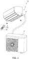
- FIG. 1 A refrigeration apparatus pertaining to an embodiment of the invention will be described below using an air conditioner as an example.
- FIG. 1 and FIG. 2 A general overview of the configuration of the air conditioner pertaining to this embodiment is shown in FIG. 1 and FIG. 2 .
- An air conditioner 1 shown in FIG. 1 is equipped with an indoor unit 3 attached, for example, to a wall surface WL of a indoor and an outdoor unit 2 installed outdoors. It will be noted in regard to FIG. 1 that the outdoor unit 2 is depicted with dashed lines because the outdoor unit 2 is located outdoors on the opposite side of the indoor unit 3 across the wall surface WL.
- FIG. 2 is shown the circuit configuration of the air conditioner 1.
- the air conditioner 1 is equipped with a refrigerant circuit 10 and can execute a vapor compression refrigeration cycle by causing refrigerant in the refrigerant circuit 10 to circulate.
- the indoor unit 3 and the outdoor unit 2 are connected to each other by communication piping 4.
- the air conditioner 1 is equipped with a control unit 50 to control the devices inside.
- a remote controller 5 is included in the air conditioner 1, and the remote controller 5 has the function of communicating with the control unit 50 using infrared, for example. Consequently, the user can use the remote controller 5 to perform various settings with respect to the air conditioner 1.
- the refrigerant circuit 10 is equipped with a compressor 11, a four way valve 12, an outdoor heat exchanger 13, an expansion mechanism 14, an accumulator 15, and an indoor heat exchanger 16.
- the compressor 11 discharges, from a discharge port to a first port of the four way valve 12, refrigerant that it has sucked in from a suction port and compressed.
- the four way valve 12 further has a second port connected to the outdoor heat exchanger 13, a third port connected to the accumulator 15, and a fourth port connected to the indoor heat exchanger 16.
- the four way valve 12 causes the refrigerant to circulate between the first port and the fourth port while simultaneously causing the refrigerant to circulate between the second port and the third port as indicated by the dashed lines. Furthermore, when the air conditioner 1 performs a cooling operation and when the air conditioner 1 performs a reverse cycle defrost operation, the four way valve 12 causes the refrigerant to circulate between the first port and the second port while simultaneously causing the refrigerant to circulate between the third port and the fourth port as indicated by the solid lines.
- the outdoor heat exchanger 13 has a gas-side inlet/outlet for mainly causing gas refrigerant to circulate between the outdoor heat exchanger 13 and the second port of the four way valve 12, and also has a liquid-side inlet/outlet for mainly causing liquid refrigerant to circulate between the outdoor heat exchanger 13 and the expansion mechanism 14.
- the outdoor heat exchanger 13 causes heat exchange to be carried out between outdoor air and the refrigerant flowing through heat transfer tubes (not shown in the drawings) connected between the liquid-side inlet/outlet and the gas-side inlet/outlet of the outdoor heat exchanger 13.
- the expansion mechanism 14 is disposed between the outdoor heat exchanger 13 and the indoor heat exchanger 16.
- the expansion mechanism 14 has the function of causing the refrigerant flowing between the outdoor heat exchanger 13 and the indoor heat exchanger 16 to expand to thereby reduce the pressure of the refrigerant.
- the indoor heat exchanger 16 has a liquid-side inlet/outlet for causing liquid refrigerant to circulate between the indoor heat exchanger 16 and the expansion mechanism 14, and also has a gas-side inlet/outlet for causing gas refrigerant to circulate between the indoor heat exchanger 16 and the fourth port of the four way valve 12.
- the indoor heat exchanger 16 causes heat exchange to be carried out between indoor air and the refrigerant flowing through heat transfer tubes (not shown in the drawings) connected between the liquid-side inlet/outlet and the gas-side inlet/outlet of the indoor heat exchanger 16.
- the accumulator 15 is disposed between the third port of the four way valve 12 and the suction port of the compressor 11.
- the refrigerant flowing from the third port of the four way valve 12 to the compressor 11 is separated into gas refrigerant and liquid refrigerant. Additionally, mainly the gas refrigerant is supplied from the accumulator 15 to the suction port of the compressor 11.
- the outdoor unit 2 is equipped with an outdoor fan 21 that generates an airflow of outdoor air that passes through the outdoor heat exchanger 13 in order to promote heat exchange between the refrigerant flowing through the heat transfer tubes and the outdoor air.
- the outdoor fan 21 is driven by an outdoor fan motor 21a whose rotational speed can be changed.
- the indoor unit 3 is equipped with an indoor fan 31 that generates an airflow of indoor air that passes through the indoor heat exchanger 16 in order to promote heat exchange between the refrigerant flowing through the heat transfer tubes and the indoor air.
- the indoor fan 31 is driven by an indoor fan motor 31a whose rotational speed can be changed.
- an air direction adjustment blade 36 is provided in the indoor unit 3.
- the indoor unit 3 shown in FIG. 1 is in a state in which its air outlet is closed off by the air direction adjustment blade 36.
- the air direction adjustment blade 36 is driven by an air direction adjustment blade drive motor 37 (see FIG. 3 ) so that warm air is blown out from the opened air outlet.
- Indoor air sucked into the indoor unit 3 is sucked in from an air inlet (not shown in the drawings) located in the top of the indoor unit 3.
- the control unit 50 has an outdoor control device 26 built into the outdoor unit 2 and an indoor control device 35 built into the indoor unit 3.
- the outdoor control device 26 and the indoor control device 35 are connected to each other by a signal line and are configured in such a way that they can send signals to and receive signals from each other.
- the outdoor control device 26 of the outdoor unit 2 controls the compressor 11, the four way valve 12, the expansion mechanism 14, and the outdoor fan 21, among other things.
- the outdoor unit 2 is equipped with an outdoor temperature sensor 22 for measuring the temperature of the outdoor air, an outdoor heat exchanger temperature sensor 23 for measuring the temperature of the refrigerant flowing through a particular place in the outdoor heat exchanger 13, an outlet pipe temperature sensor 24 for detecting the temperature of the refrigerant flowing out from the gas-side inlet/outlet of the outdoor heat exchanger 13 functioning as an evaporator in the heating operation, and a suction pipe temperature sensor 25 for detecting the temperature of the gas refrigerant sucked into the compressor 11.
- the outdoor control device 26 is connected to the outdoor temperature sensor 22 and the outdoor heat exchanger temperature sensor 23 in order to receive signals relating to the temperatures that the outdoor temperature sensor 22 and the outdoor heat exchanger temperature sensor 23 have measured.
- the outdoor control device 26 includes a CPU (not shown in the drawings) and a memory (not shown in the drawings), for example, and is configured to be able to control the outdoor unit 2 in accordance with a stored program or the like.
- the indoor control device 35 of the indoor unit 3 controls the indoor fan 31 and the like, among other things.
- the indoor unit 3 is equipped with an indoor temperature sensor 32 for measuring the temperature of the indoor air and an indoor heat exchanger temperature sensor 33 for measuring the temperature of the refrigerant flowing through a particular place in the indoor heat exchanger 16.
- the indoor control device 35 is connected to the indoor temperature sensor 32 and the indoor heat exchanger temperature sensor 33 in order to receive signals relating to the temperatures that the indoor temperature sensor 32 and the indoor heat exchanger temperature sensor 33 have measured.
- the indoor control device 35 includes a CPU (not shown in the drawings) and a memory (not shown in the drawings), for example, and is configured to be able to control the outdoor unit 2 in accordance with a stored program or the like.
- the remote controller 5 has a liquid crystal display 5a and buttons 5b shown in FIG. 1 .
- Provided in the remote controller 5 are an operation switch 51, an operating mode switch 52, a temperature setting switch 53, and an air volume setting switch 54, and the user can use the buttons 5b to operate these switches.
- the operation switch 51 is a switch for switching between operating and stopping the air conditioner 1, so that each time the operation switch 51 is operated, the air conditioner 1 switches between operating and stopping.
- the operating mode switch 52 is used, for example, when selecting the cooling operation and the heating operation.
- the temperature setting switch 53 is a switch used for the user to input the desired indoor temperature.
- the air volume setting switch 54 is a switch used for the user to input the desired air volume.
- the control unit 50 sets a target indoor temperature Tt on the basis of a set temperature Ts that has been input using the temperature setting switch 53. For example, suppose that the target indoor temperature Tt is (Ts + ⁇ 1), which is the sum of the set temperature Ts and a certain value ⁇ 1.
- the control unit 50 causes the air conditioner 1 to thermostat off. It will be noted that the control unit 50 causes the air conditioner 1 to thermostat on if the indoor temperature Tr is lower than a value (Ts - ⁇ 2), which is the difference between the set temperature Ts and a certain value ⁇ 2.
- the control unit 50 controls the various devices configuring the air conditioner 1 on the basis of the measurement values of the various sensors and commands input from the remote controller 5. Furthermore, the control unit 50 uses the liquid crystal display 5a of the remote controller 5 to notify the user of the status of input commands and the status of control.
- the four way valve 12 switches to the state indicated by the dashed lines shown in FIG. 2 . That is, high-temperature high-pressure gas refrigerant discharged from the compressor 11 flows via the four way valve 12 into the indoor heat exchanger 16. At this time, the indoor heat exchanger 16 functions as a condenser. For that reason, as the refrigerant flows through the indoor heat exchanger 16, it exchanges heat with the indoor air and thereby warms the indoor air, is itself cooled, condenses, and changes from gas refrigerant to liquid refrigerant.
- the low-temperature high-pressure refrigerant whose heat has been taken away in the indoor heat exchanger 16 has its pressure reduced by the expansion mechanism 14 and changes to low-temperature low-pressure refrigerant.
- the refrigerant that has flowed via the expansion mechanism 14 into the outdoor heat exchanger 13 exchanges heat with the outdoor air and is thereby warmed, evaporates, and changes from liquid refrigerant to gas refrigerant.
- the outdoor heat exchanger 13 functions as an evaporator.
- refrigerant comprising mainly low-temperature gas refrigerant is sucked from the outdoor heat exchanger 13 via the four way valve 12 and the accumulator 15 into the compressor 11.
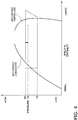
- FIG. 4 is shown the concept of a Mollier diagram (p-h diagram) in the heating operation.
- the air conditioner 1 is configured in such a way that the refrigerant circulates while sequentially repeatedly undergoing the four state changes of evaporation, compression, condensation, and expansion.
- a high-pressure value P1 of the refrigerant circuit 10 shown in FIG. 1 is the condensation pressure of the outdoor heat exchanger 13, and a low-pressure value P2 of the refrigerant circuit 10 is the evaporation pressure of the indoor heat exchanger 16.
- the high-pressure value P1 (condensation pressure) is substantially the same as the discharge pressure of the compressor 11.
- the four way valve 12 switches to the state indicated by the solid lines shown in FIG. 2 . That is, high-temperature high-pressure gas refrigerant discharged from the compressor 11 flows via the four way valve 12 into the outdoor heat exchanger 13. At this time, the outdoor heat exchanger 13 functions as a condenser. For that reason, as the refrigerant flows through the outdoor heat exchanger 13, it exchanges heat with the outdoor air and is thereby cooled, condenses, and changes from gas refrigerant to liquid refrigerant.
- the low-temperature high-pressure refrigerant whose heat has been taken away in the outdoor heat exchanger 13 has its pressure reduced by the expansion mechanism 14 and changes to low-temperature low-pressure refrigerant.
- the refrigerant that has flowed via the expansion mechanism 14 into the indoor heat exchanger 16 exchanges heat with the indoor air and thereby cools the indoor air, is itself warmed, evaporates, and changes from liquid refrigerant to gas refrigerant.
- the indoor heat exchanger 16 functions as an evaporator. Then, refrigerant comprising mainly low-temperature gas refrigerant is sucked from the indoor heat exchanger 16 via the four way valve 12 and the accumulator 15 into the compressor 11.
- the reverse cycle defrost operation is performed to remove frost sticking to the outdoor heat exchanger 13 owing to the heating operation having been performed. Consequently, the air conditioner 1 switches to the reverse cycle defrost operation in the middle of the heating operation, and when the reverse cycle defrost operation ends, the air conditioner 1 reverts back to the heating operation.
- the reverse cycle defrost operation as in the cooling operation, the four way valve 12 switches to the state indicated by the solid lines shown in FIG. 2 . Additionally, in the reverse cycle defrost operation also, the same vapor compressor refrigeration cycle as in the cooling operation is repeated.
- a reverse cycle defrost operation that repeats a vapor compression refrigeration cycle in which the refrigerant flows in the order of the compressor 11, the outdoor heat exchanger 13, the expansion mechanism 14, and the indoor heat exchanger 16.
- a high-pressure value P3 of the refrigerant circuit 10 indicated by the dashed lines in FIG. 4 is the condensation pressure of the outdoor heat exchanger 13 functioning as a condenser.
- the high-pressure value P3 (condensation pressure) is substantially the same as the discharge pressure of the compressor 11. As shown in FIG. 4 , the high-pressure value P3 of the refrigerant circuit 10 in the reverse cycle defrost operation is set lower in comparison to the high-pressure value P1 of the refrigerant circuit 10 in the heating operation.
- the outdoor control device 26 of the outdoor unit 2 decides to perform defrosting when heating control is being performed.
- a defrost request flag shown in FIG. 8(b) changes from "0" to "1” and a defrost request signal is sent from the outdoor control device 26 of the outdoor unit 2 to the indoor control device 35 of the indoor unit 3.
- the indoor control device 35 When completing preparations for the defrost operation conclude in the indoor unit 3 that has received the defrost request signal, the indoor control device 35 sends a defrost permission signal to the outdoor control device 26.
- the outdoor control device 26 receives the defrost permission signal, the outdoor control device 26 starts defrost control and sends to the indoor control device 35 a signal indicated that defrosting is currently in progress.
- the defrost request flag in FIG. 8(b) changes from "1" to "0" and a normal notification signal notifying the indoor control device 35 of the indoor unit 3 that the air conditioner 1 will return to the normal heating operation is sent from the outdoor control device 26 to the indoor control device 35.
- the indoor unit 3 that has received the normal notification signal reverts to heating control for the heating operation.
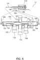
- FIG. 5 is a perspective view of the four way valve 12. Furthermore, FIG. 6 and FIG. 7 are schematic sectional views for describing the configuration of the four way valve 12.
- the four way valve 12 is equipped with a body mechanism 150 and a pilot mechanism 170.
- the body mechanism 150 has a cylinder 151, a slide mount 153, and a slide valve 152 (see FIG. 6 ).
- the slide mount 153 is a mount disposed inside the central section of the cylinder 151.
- a third port 12c is disposed in the center of the slide mount 153, and a second port 12b and a fourth port 12d are provided on both sides of the third port 12c along the axial direction of the cylinder.
- a first port 12a is provided in a position opposing the third port 12c of the slide mount 153.
- the first port 12a is connected to the discharge port of the compressor 11, so during the heating operation, high pressure acts on the first port 12a.
- the third port 12c is connected to the suction opening of the compressor 11, so during the heating operation, only low pressure acts on the third port 12c.
- the slide valve 152 moves and high pressure and low pressure alternately act on the second port 12b and the fourth port 12d.
- the state shown in FIG. 6 is a state during the reverse cycle defrost operation or during the cooling operation and is the state of connection indicated by the solid lines in FIG. 2 .
- the state shown in FIG. 7 is a state during the heating operation and is the state of connection indicated by the dashed lines in FIG. 2 .
- the slide valve 152 is disposed inside the cylinder 151 and is configured in such a way that it may freely slide in the axial direction of the cylinder 151.
- the slide valve 152 slides on the slide mount 153.
- the slide valve 152 is processed in such a way that its central portion is shaped like an upside-down U.
- the slide valve 152 connects in such a way that the refrigerant can flow through it between mutually adjacent ports because of the upside-down U-shaped section.
- Partition members 154 and 155 are on both sides of the slide valve 152, a first chamber 156 is formed between the partition member 154 and the cylinder 151, and a second chamber 157 is formed between the partition member 155 and the cylinder 151.
- the slide valve 152 is driven by the pressure difference between the first chamber 156 and the second chamber 157.
- the body mechanism 150 and the pilot mechanism 170 are connected to each other by four pilot tubes comprising a first pilot tube 181, a second pilot tube 182, a third pilot tube 183, and a fourth pilot tube 184.
- the first pilot tube 181 is connected to the first port 12a.
- the third pilot tube 183 is connected to the third port 12c.
- the second pilot tube 182 is connected to the first chamber 156, and the fourth pilot tube 184 is connected to the second chamber 157.
- the pilot mechanism 170 uses a built-in spring and electromagnet to switch connection from the first pilot tube 181 to the third pilot tube 183. This switches the four way valve 12 between the state shown in FIG. 6 , which switches the first chamber 156 of the cylinder 151 of the body mechanism 150 to a low pressure and switches the second chamber 157 to a high pressure (hereinafter called a "left-position state"), and the state shown in FIG. 7 , which switches the first chamber 156 to a high pressure and switches the second chamber 157 to a low pressure (hereinafter called a "right-position state").
- the slide valve 152 inside the cylinder 151 is positioned on the left side as shown in FIG. 6 , so that the first port 12a and the second port 12b communicate with each other and the fourth port 12d and the third port 12c communicate with each other.
- the first pilot tube 181 and the second pilot tube 182 are connected to each other, and the third pilot tube 183 and the fourth pilot tube 184 are connected to each other.
- the electromagnet of the pilot mechanism 170 is not excited, so the slide valve 152 is in the right-position state shown in FIG. 7 , so that the first port 12a and the fourth port 12d communicate with each other and the second port 12b and the third port 12c communicate with each other.
- the pressure difference between both ends of the cylinder 151 becomes a pressure difference whereby the slide valve 152 moves to the left side, and the slide valve 152 moves to the left side.
- the first port 12a and the second port 12b communicate with each other and the third port 12c and the fourth port 12d communicate with each other.
- the upper limit on the rotational speed of the indoor fan 31 is provided in correspondence to the maximum air volume that can be input by the air volume setting switch 54.
- the control unit 50 limits the rotational speed of the indoor fan 31 to a rotational speed that is smaller than the rotational speed at the maximum air volume. Because this limit for defrosting is provided on the rotational speed of the indoor fan 31, the feeling of discomfort that the user feels because of cool air blown out in the defrost operation is suppressed.
- control that gradually lowers the operating frequency of the compressor 11 is started beginning at time t1 by the outdoor control device 26.
- the compressor 11 reaches a predetermined operating frequency Fmin.
- the rate of decrease (normal frequency decrease rate) in the operating frequency when it reaches time t2 from time t1 is, for example, 2 Hz/sec.
- the rate of increase in the operating frequency in the heating operation is also set to 2 Hz/sec.
- the four way valve 12 is switched from the heating side to the cooling side. Namely, the state of connection of the four way valve 12 shown in FIG. 5 is switched from the state of connection indicated by the dashed lines in FIG. 2 to the state of connection indicated by the solid lines.
- the compressor 11 starts to increase its rotational speed (time t5 in FIG. 8(a) ).
- the operating frequency of the compressor 11 (see FIG. 8(a) ) and the opening degree of the expansion valve 14 (see FIG. 8(b) ) are controlled by the outdoor control device 26 in accordance with a sequence stored in the memory.
- the outdoor control device 26 performs a defrost conclusion determination for ending the defrost operation.
- a determination to conclude the defrost operation is reached in the defrost conclusion determination for ending the defrost operation, as shown in FIG. 8(c) , at time t6 a calm operation command changes from "0" to "1" and a command to perform a calm operation is given.
- the outdoor control device 26 gradually lowers the operating frequency of the compressor 11 to the calm operation frequency Fmin (time t7) and maintains the calm operation frequency Fmin for a predetermined amount of time (t8 - t7).
- the high-pressure value P3 of the refrigerant circuit 10 is lower than the high-pressure value P1 of the refrigerant circuit 10 in the heating operation as shown in FIG. 4 .
- the rate of decrease (end-of-defrost frequency decrease rate) in the operating frequency of the compressor 11 is set, for example, to 10 Hz/sec.
- the rotational frequency of the compressor 11 that had been operated at several tens of Hz is lowered in several seconds to ten or so Hz (the calm operation frequency Fmin).
- the end-of-defrost frequency decrease rate is set to five times the normal frequency decrease rate, but an improvement in heating capacity can be expected even when the end-of-defrost frequency decrease rate is set, for example, to two or more times the normal frequency decrease rate.
- the reverse cycle defrost operation defrost operation
- the heating operation is interrupted. Consequently, it becomes easier to obtain a higher heating capacity, and particularly a higher low-temperature heating capacity, the larger the value of heating operation time ⁇ (heating operation time + defrost operation time) is.
- the reverse cycle defrost operation to the heating operation in a state in which the calm operation frequency Fmin is maintained without stopping the compressor 11, it becomes easier to obtain an even higher low-temperature heating capacity.
- the pressure difference between the first port 12a and the third port 12c of the four way valve 12 can be mitigated. Because of that, in comparison to the case of not performing the calm operation, for example, by performing the calm operation, the shock sound of the four way valve 12 is extremely remarkedly suppressed. Then, when the pressure equalization of the four way valve 12 has ended, as shown in FIG.
- the four way valve 12 is switched from the connection indicated by the solid lines to the connection indicated by the dashed lines, namely, the path whereby the refrigerant discharged from the compressor 11 is sent to the indoor heat exchanger 16 and the refrigerant flowing out from the outdoor heat exchanger 13 is sucked into the compressor 11 (time t8).
- the outdoor control device 26 of the control unit 50 changes the calm operation command from "1" to "0" and starts increasing the operating frequency of the compressor 11.
- the outdoor control device 26 starts driving the outdoor fan 21.
- the indoor control device 35 also changes the upper limit on the rotational speed of the indoor fan 31 from the limit for defrosting to the normal limit.
- the switching mechanism 12 was described as the switching mechanism, but the switching mechanism is not limited to the four way valve 12.
- the switching mechanism may also be a switching mechanism other than a four way valve provided that it is used to switch between the heating operation and the defrost operation and requires pressure equalization between the port connected to the discharge port of the compressor 11 and the port connected to the suction port of the compressor in order to suppress noise when switching between these operations.
- the end-of-defrost frequency decrease rate of the compressor 11 during the defrost operation from time t6 to time t7 shown in FIG. 8(a) is faster than the normal frequency decrease rate of the compressor 11 from time t1 to time t2, for example.
- the compressor 11 can be made to quickly reach an operating frequency at which pressure equalization of the four way valve 12 that is the switching mechanism is possible when ending the defrost operation, so the amount of time until switching the four way valve 12 can be shortened.
- the defrost operation time is shortened, noise that occurs when reverting to the heating operation is suppressed, and it becomes easy to ensure heating capacity.
- the end-of-defrost frequency decrease rate is set to 10 Hz/sec, which is a decrease rate that is two or more times the normal frequency decrease rate of 2 Hz/sec, the effect of shortening the defrost operation time becomes greater.
- the decrease rate it is preferable for the decrease rate to be as short as possible to the extent that the compressor 11 is not adversely affected, and even more preferable for the end-of-defrost decrease rate to be five or more times the normal frequency decrease rate (end-of-defrost frequency decrease rate / normal frequency decrease rate) as in the above embodiment.
- FIG. 8(a) shows, with dashed lines, the working of the compressor 11 in a case where the operating frequency of the compressor 11 is decreased beginning at time t6 at the normal frequency decrease rate instead of the end-of-defrost frequency decrease rate.
- the dashed lines and the solid lines the amount of time from time t8 to time t9 is shortened in comparison to what has conventionally been the case.
- maintaining the calm operation frequency Fmin an example of maintaining an operating frequency equal to or greater than a predetermined value
- maintaining the calm operation frequency Fmin means that the compressor 11 is driven at an operating frequency equal to or greater than a predetermined value when it has reverted to the heating operation.
- Patent Document 1 Japanese Patent Unexamined Publication No. 2014-129957
Landscapes
- Engineering & Computer Science (AREA)
- Mechanical Engineering (AREA)
- General Engineering & Computer Science (AREA)
- Physics & Mathematics (AREA)
- Thermal Sciences (AREA)
- Chemical & Material Sciences (AREA)
- Combustion & Propulsion (AREA)
- Air Conditioning Control Device (AREA)
- Air-Conditioning For Vehicles (AREA)
Applications Claiming Priority (2)
| Application Number | Priority Date | Filing Date | Title |
|---|---|---|---|
| JP2015215168A JP6210103B2 (ja) | 2015-10-30 | 2015-10-30 | 冷凍装置 |
| PCT/JP2016/081631 WO2017073577A1 (fr) | 2015-10-30 | 2016-10-25 | Dispositif de réfrigération |
Publications (3)
| Publication Number | Publication Date |
|---|---|
| EP3370021A1 true EP3370021A1 (fr) | 2018-09-05 |
| EP3370021A4 EP3370021A4 (fr) | 2018-09-05 |
| EP3370021B1 EP3370021B1 (fr) | 2021-03-03 |
Family
ID=58631607
Family Applications (1)
| Application Number | Title | Priority Date | Filing Date |
|---|---|---|---|
| EP16859807.6A Active EP3370021B1 (fr) | 2015-10-30 | 2016-10-25 | Dispositif de réfrigération |
Country Status (7)
| Country | Link |
|---|---|
| US (1) | US10753662B2 (fr) |
| EP (1) | EP3370021B1 (fr) |
| JP (1) | JP6210103B2 (fr) |
| CN (1) | CN108351136B (fr) |
| AU (1) | AU2016344865B2 (fr) |
| ES (1) | ES2861532T3 (fr) |
| WO (1) | WO2017073577A1 (fr) |
Families Citing this family (8)
| Publication number | Priority date | Publication date | Assignee | Title |
|---|---|---|---|---|
| BR112018014946B1 (pt) * | 2016-01-25 | 2023-04-18 | Bitzer Kühlmaschinenbau Gmbh | Método para controlar um sistema compressor |
| JP6620800B2 (ja) * | 2017-10-30 | 2019-12-18 | ダイキン工業株式会社 | 空調装置 |
| US11002454B2 (en) * | 2019-07-23 | 2021-05-11 | Lennox Industries Inc. | Detection of refrigerant side faults |
| CN114096792B (zh) * | 2019-07-25 | 2023-04-14 | 三菱电机株式会社 | 制冷循环装置 |
| CN110906581A (zh) * | 2019-12-03 | 2020-03-24 | 无锡同方人工环境有限公司 | 变频式空气源热泵机组的除霜方法 |
| CN111981641B (zh) * | 2020-08-20 | 2022-03-01 | 青岛海信日立空调系统有限公司 | 一种空调除霜控制方法及空调系统 |
| CN114893867B (zh) * | 2022-06-21 | 2023-07-14 | 珠海格力节能环保制冷技术研究中心有限公司 | 空调器的控制方法及空调器 |
| US12529489B2 (en) * | 2022-07-11 | 2026-01-20 | Rheem Manufacturing Company | Enhanced heat pump defrost without use of auxiliary heat |
Family Cites Families (7)
| Publication number | Priority date | Publication date | Assignee | Title |
|---|---|---|---|---|
| JPS6069446A (ja) * | 1983-09-27 | 1985-04-20 | Toshiba Corp | 圧縮機の運転制御方法 |
| KR920001142A (ko) * | 1990-06-01 | 1992-01-30 | 강진구 | 공기 조화기의 압축기 제어 방법 |
| US5285646A (en) * | 1990-06-01 | 1994-02-15 | Samsung Electronics Co., Ltd. | Method for reversing a compressor in a heat pump |
| JP2008256264A (ja) * | 2007-04-05 | 2008-10-23 | Matsushita Electric Ind Co Ltd | 空気調和機 |
| CN101957067B (zh) * | 2010-11-01 | 2012-09-05 | 江苏天舒电器有限公司 | 一种热泵热水机的变频控制方法 |
| JP5516695B2 (ja) * | 2012-10-31 | 2014-06-11 | ダイキン工業株式会社 | 空気調和装置 |
| JP6113503B2 (ja) * | 2012-12-28 | 2017-04-12 | ダイキン工業株式会社 | ヒートポンプ装置 |
-
2015
- 2015-10-30 JP JP2015215168A patent/JP6210103B2/ja active Active
-
2016
- 2016-10-25 WO PCT/JP2016/081631 patent/WO2017073577A1/fr not_active Ceased
- 2016-10-25 CN CN201680062695.3A patent/CN108351136B/zh active Active
- 2016-10-25 AU AU2016344865A patent/AU2016344865B2/en active Active
- 2016-10-25 ES ES16859807T patent/ES2861532T3/es active Active
- 2016-10-25 US US15/771,293 patent/US10753662B2/en active Active
- 2016-10-25 EP EP16859807.6A patent/EP3370021B1/fr active Active
Also Published As
| Publication number | Publication date |
|---|---|
| JP2017083144A (ja) | 2017-05-18 |
| US20180313592A1 (en) | 2018-11-01 |
| AU2016344865B2 (en) | 2019-09-26 |
| WO2017073577A1 (fr) | 2017-05-04 |
| EP3370021A4 (fr) | 2018-09-05 |
| ES2861532T3 (es) | 2021-10-06 |
| JP6210103B2 (ja) | 2017-10-11 |
| CN108351136B (zh) | 2021-04-13 |
| AU2016344865A1 (en) | 2018-06-07 |
| CN108351136A (zh) | 2018-07-31 |
| US10753662B2 (en) | 2020-08-25 |
| EP3370021B1 (fr) | 2021-03-03 |
Similar Documents
| Publication | Publication Date | Title |
|---|---|---|
| EP3370021B1 (fr) | Dispositif de réfrigération | |
| EP2762806B1 (fr) | Réfrigérateur | |
| EP2719966B1 (fr) | Dispositif d'air conditionné de réfrigération | |
| EP3339762B1 (fr) | Climatiseur | |
| KR101918224B1 (ko) | 냉장고 및 그 제상 운전 방법 | |
| JP7183424B2 (ja) | 冷凍サイクル装置 | |
| EP3062031A1 (fr) | Climatiseur | |
| US20180266743A1 (en) | Air-conditioning apparatus | |
| CN108759247A (zh) | 一种具有深冷功能的双系统风冷冰箱及其制冷控制方法 | |
| JP2018128158A (ja) | 空気調和機 | |
| EP3674631B1 (fr) | Réfrigérateur et son procédé de commande | |
| US11519623B2 (en) | Air-conditioning apparatus | |
| US7475557B2 (en) | Refrigerator | |
| EP3705807B1 (fr) | Dispositif à cycle frigorifique | |
| WO2022259287A1 (fr) | Dispositif de réfrigération | |
| CN113883681A (zh) | 用于制冷系统的控制方法及制冷系统 | |
| EP4656971A1 (fr) | Dispositif frigorifique | |
| KR20040048792A (ko) | 시차분할 멀티사이클형 냉각 장치 | |
| JP2014119144A (ja) | 空気調和機 | |
| JP2021028549A (ja) | 熱源ユニットおよびそれを備える冷凍装置 | |
| JP2003014319A (ja) | 冷凍システム | |
| JP2005233451A (ja) | 空気調和装置 |
Legal Events
| Date | Code | Title | Description |
|---|---|---|---|
| STAA | Information on the status of an ep patent application or granted ep patent |
Free format text: STATUS: THE INTERNATIONAL PUBLICATION HAS BEEN MADE |
|
| PUAI | Public reference made under article 153(3) epc to a published international application that has entered the european phase |
Free format text: ORIGINAL CODE: 0009012 |
|
| STAA | Information on the status of an ep patent application or granted ep patent |
Free format text: STATUS: REQUEST FOR EXAMINATION WAS MADE |
|
| 17P | Request for examination filed |
Effective date: 20180522 |
|
| A4 | Supplementary search report drawn up and despatched |
Effective date: 20180717 |
|
| AK | Designated contracting states |
Kind code of ref document: A1 Designated state(s): AL AT BE BG CH CY CZ DE DK EE ES FI FR GB GR HR HU IE IS IT LI LT LU LV MC MK MT NL NO PL PT RO RS SE SI SK SM TR |
|
| AX | Request for extension of the european patent |
Extension state: BA ME |
|
| DAV | Request for validation of the european patent (deleted) | ||
| DAX | Request for extension of the european patent (deleted) | ||
| STAA | Information on the status of an ep patent application or granted ep patent |
Free format text: STATUS: EXAMINATION IS IN PROGRESS |
|
| 17Q | First examination report despatched |
Effective date: 20200226 |
|
| GRAJ | Information related to disapproval of communication of intention to grant by the applicant or resumption of examination proceedings by the epo deleted |
Free format text: ORIGINAL CODE: EPIDOSDIGR1 |
|
| STAA | Information on the status of an ep patent application or granted ep patent |
Free format text: STATUS: GRANT OF PATENT IS INTENDED |
|
| GRAP | Despatch of communication of intention to grant a patent |
Free format text: ORIGINAL CODE: EPIDOSNIGR1 |
|
| RIC1 | Information provided on ipc code assigned before grant |
Ipc: F25B 47/02 20060101AFI20201021BHEP Ipc: F25B 13/00 20060101ALN20201021BHEP |
|
| INTG | Intention to grant announced |
Effective date: 20201110 |
|
| GRAS | Grant fee paid |
Free format text: ORIGINAL CODE: EPIDOSNIGR3 |
|
| GRAA | (expected) grant |
Free format text: ORIGINAL CODE: 0009210 |
|
| STAA | Information on the status of an ep patent application or granted ep patent |
Free format text: STATUS: THE PATENT HAS BEEN GRANTED |
|
| AK | Designated contracting states |
Kind code of ref document: B1 Designated state(s): AL AT BE BG CH CY CZ DE DK EE ES FI FR GB GR HR HU IE IS IT LI LT LU LV MC MK MT NL NO PL PT RO RS SE SI SK SM TR |
|
| RAP1 | Party data changed (applicant data changed or rights of an application transferred) |
Owner name: DAIKIN INDUSTRIES, LTD. |
|
| REG | Reference to a national code |
Ref country code: GB Ref legal event code: FG4D |
|
| REG | Reference to a national code |
Ref country code: AT Ref legal event code: REF Ref document number: 1367647 Country of ref document: AT Kind code of ref document: T Effective date: 20210315 Ref country code: CH Ref legal event code: EP |
|
| REG | Reference to a national code |
Ref country code: DE Ref legal event code: R096 Ref document number: 602016053773 Country of ref document: DE |
|
| REG | Reference to a national code |
Ref country code: IE Ref legal event code: FG4D |
|
| REG | Reference to a national code |
Ref country code: LT Ref legal event code: MG9D |
|
| PG25 | Lapsed in a contracting state [announced via postgrant information from national office to epo] |
Ref country code: BG Free format text: LAPSE BECAUSE OF FAILURE TO SUBMIT A TRANSLATION OF THE DESCRIPTION OR TO PAY THE FEE WITHIN THE PRESCRIBED TIME-LIMIT Effective date: 20210603 Ref country code: LT Free format text: LAPSE BECAUSE OF FAILURE TO SUBMIT A TRANSLATION OF THE DESCRIPTION OR TO PAY THE FEE WITHIN THE PRESCRIBED TIME-LIMIT Effective date: 20210303 Ref country code: FI Free format text: LAPSE BECAUSE OF FAILURE TO SUBMIT A TRANSLATION OF THE DESCRIPTION OR TO PAY THE FEE WITHIN THE PRESCRIBED TIME-LIMIT Effective date: 20210303 Ref country code: HR Free format text: LAPSE BECAUSE OF FAILURE TO SUBMIT A TRANSLATION OF THE DESCRIPTION OR TO PAY THE FEE WITHIN THE PRESCRIBED TIME-LIMIT Effective date: 20210303 Ref country code: GR Free format text: LAPSE BECAUSE OF FAILURE TO SUBMIT A TRANSLATION OF THE DESCRIPTION OR TO PAY THE FEE WITHIN THE PRESCRIBED TIME-LIMIT Effective date: 20210604 Ref country code: NO Free format text: LAPSE BECAUSE OF FAILURE TO SUBMIT A TRANSLATION OF THE DESCRIPTION OR TO PAY THE FEE WITHIN THE PRESCRIBED TIME-LIMIT Effective date: 20210603 |
|
| REG | Reference to a national code |
Ref country code: NL Ref legal event code: MP Effective date: 20210303 |
|
| REG | Reference to a national code |
Ref country code: AT Ref legal event code: MK05 Ref document number: 1367647 Country of ref document: AT Kind code of ref document: T Effective date: 20210303 |
|
| PG25 | Lapsed in a contracting state [announced via postgrant information from national office to epo] |
Ref country code: LV Free format text: LAPSE BECAUSE OF FAILURE TO SUBMIT A TRANSLATION OF THE DESCRIPTION OR TO PAY THE FEE WITHIN THE PRESCRIBED TIME-LIMIT Effective date: 20210303 Ref country code: RS Free format text: LAPSE BECAUSE OF FAILURE TO SUBMIT A TRANSLATION OF THE DESCRIPTION OR TO PAY THE FEE WITHIN THE PRESCRIBED TIME-LIMIT Effective date: 20210303 Ref country code: PL Free format text: LAPSE BECAUSE OF FAILURE TO SUBMIT A TRANSLATION OF THE DESCRIPTION OR TO PAY THE FEE WITHIN THE PRESCRIBED TIME-LIMIT Effective date: 20210303 Ref country code: SE Free format text: LAPSE BECAUSE OF FAILURE TO SUBMIT A TRANSLATION OF THE DESCRIPTION OR TO PAY THE FEE WITHIN THE PRESCRIBED TIME-LIMIT Effective date: 20210303 |
|
| PG25 | Lapsed in a contracting state [announced via postgrant information from national office to epo] |
Ref country code: NL Free format text: LAPSE BECAUSE OF FAILURE TO SUBMIT A TRANSLATION OF THE DESCRIPTION OR TO PAY THE FEE WITHIN THE PRESCRIBED TIME-LIMIT Effective date: 20210303 |
|
| REG | Reference to a national code |
Ref country code: ES Ref legal event code: FG2A Ref document number: 2861532 Country of ref document: ES Kind code of ref document: T3 Effective date: 20211006 |
|
| PG25 | Lapsed in a contracting state [announced via postgrant information from national office to epo] |
Ref country code: AT Free format text: LAPSE BECAUSE OF FAILURE TO SUBMIT A TRANSLATION OF THE DESCRIPTION OR TO PAY THE FEE WITHIN THE PRESCRIBED TIME-LIMIT Effective date: 20210303 Ref country code: SM Free format text: LAPSE BECAUSE OF FAILURE TO SUBMIT A TRANSLATION OF THE DESCRIPTION OR TO PAY THE FEE WITHIN THE PRESCRIBED TIME-LIMIT Effective date: 20210303 Ref country code: CZ Free format text: LAPSE BECAUSE OF FAILURE TO SUBMIT A TRANSLATION OF THE DESCRIPTION OR TO PAY THE FEE WITHIN THE PRESCRIBED TIME-LIMIT Effective date: 20210303 Ref country code: EE Free format text: LAPSE BECAUSE OF FAILURE TO SUBMIT A TRANSLATION OF THE DESCRIPTION OR TO PAY THE FEE WITHIN THE PRESCRIBED TIME-LIMIT Effective date: 20210303 |
|
| PG25 | Lapsed in a contracting state [announced via postgrant information from national office to epo] |
Ref country code: IS Free format text: LAPSE BECAUSE OF FAILURE TO SUBMIT A TRANSLATION OF THE DESCRIPTION OR TO PAY THE FEE WITHIN THE PRESCRIBED TIME-LIMIT Effective date: 20210703 Ref country code: PT Free format text: LAPSE BECAUSE OF FAILURE TO SUBMIT A TRANSLATION OF THE DESCRIPTION OR TO PAY THE FEE WITHIN THE PRESCRIBED TIME-LIMIT Effective date: 20210705 Ref country code: RO Free format text: LAPSE BECAUSE OF FAILURE TO SUBMIT A TRANSLATION OF THE DESCRIPTION OR TO PAY THE FEE WITHIN THE PRESCRIBED TIME-LIMIT Effective date: 20210303 Ref country code: SK Free format text: LAPSE BECAUSE OF FAILURE TO SUBMIT A TRANSLATION OF THE DESCRIPTION OR TO PAY THE FEE WITHIN THE PRESCRIBED TIME-LIMIT Effective date: 20210303 |
|
| REG | Reference to a national code |
Ref country code: DE Ref legal event code: R097 Ref document number: 602016053773 Country of ref document: DE |
|
| PLBE | No opposition filed within time limit |
Free format text: ORIGINAL CODE: 0009261 |
|
| STAA | Information on the status of an ep patent application or granted ep patent |
Free format text: STATUS: NO OPPOSITION FILED WITHIN TIME LIMIT |
|
| PG25 | Lapsed in a contracting state [announced via postgrant information from national office to epo] |
Ref country code: AL Free format text: LAPSE BECAUSE OF FAILURE TO SUBMIT A TRANSLATION OF THE DESCRIPTION OR TO PAY THE FEE WITHIN THE PRESCRIBED TIME-LIMIT Effective date: 20210303 Ref country code: DK Free format text: LAPSE BECAUSE OF FAILURE TO SUBMIT A TRANSLATION OF THE DESCRIPTION OR TO PAY THE FEE WITHIN THE PRESCRIBED TIME-LIMIT Effective date: 20210303 |
|
| 26N | No opposition filed |
Effective date: 20211206 |
|
| PG25 | Lapsed in a contracting state [announced via postgrant information from national office to epo] |
Ref country code: SI Free format text: LAPSE BECAUSE OF FAILURE TO SUBMIT A TRANSLATION OF THE DESCRIPTION OR TO PAY THE FEE WITHIN THE PRESCRIBED TIME-LIMIT Effective date: 20210303 |
|
| REG | Reference to a national code |
Ref country code: CH Ref legal event code: PL |
|
| PG25 | Lapsed in a contracting state [announced via postgrant information from national office to epo] |
Ref country code: IS Free format text: LAPSE BECAUSE OF FAILURE TO SUBMIT A TRANSLATION OF THE DESCRIPTION OR TO PAY THE FEE WITHIN THE PRESCRIBED TIME-LIMIT Effective date: 20210703 |
|
| REG | Reference to a national code |
Ref country code: BE Ref legal event code: MM Effective date: 20211031 |
|
| PG25 | Lapsed in a contracting state [announced via postgrant information from national office to epo] |
Ref country code: MC Free format text: LAPSE BECAUSE OF FAILURE TO SUBMIT A TRANSLATION OF THE DESCRIPTION OR TO PAY THE FEE WITHIN THE PRESCRIBED TIME-LIMIT Effective date: 20210303 |
|
| PG25 | Lapsed in a contracting state [announced via postgrant information from national office to epo] |
Ref country code: LU Free format text: LAPSE BECAUSE OF NON-PAYMENT OF DUE FEES Effective date: 20211025 Ref country code: BE Free format text: LAPSE BECAUSE OF NON-PAYMENT OF DUE FEES Effective date: 20211031 |
|
| PG25 | Lapsed in a contracting state [announced via postgrant information from national office to epo] |
Ref country code: LI Free format text: LAPSE BECAUSE OF NON-PAYMENT OF DUE FEES Effective date: 20211031 Ref country code: CH Free format text: LAPSE BECAUSE OF NON-PAYMENT OF DUE FEES Effective date: 20211031 |
|
| PG25 | Lapsed in a contracting state [announced via postgrant information from national office to epo] |
Ref country code: IE Free format text: LAPSE BECAUSE OF NON-PAYMENT OF DUE FEES Effective date: 20211025 |
|
| PG25 | Lapsed in a contracting state [announced via postgrant information from national office to epo] |
Ref country code: HU Free format text: LAPSE BECAUSE OF FAILURE TO SUBMIT A TRANSLATION OF THE DESCRIPTION OR TO PAY THE FEE WITHIN THE PRESCRIBED TIME-LIMIT; INVALID AB INITIO Effective date: 20161025 |
|
| PG25 | Lapsed in a contracting state [announced via postgrant information from national office to epo] |
Ref country code: CY Free format text: LAPSE BECAUSE OF FAILURE TO SUBMIT A TRANSLATION OF THE DESCRIPTION OR TO PAY THE FEE WITHIN THE PRESCRIBED TIME-LIMIT Effective date: 20210303 |
|
| P01 | Opt-out of the competence of the unified patent court (upc) registered |
Effective date: 20230525 |
|
| PG25 | Lapsed in a contracting state [announced via postgrant information from national office to epo] |
Ref country code: MK Free format text: LAPSE BECAUSE OF FAILURE TO SUBMIT A TRANSLATION OF THE DESCRIPTION OR TO PAY THE FEE WITHIN THE PRESCRIBED TIME-LIMIT Effective date: 20210303 |
|
| PG25 | Lapsed in a contracting state [announced via postgrant information from national office to epo] |
Ref country code: MT Free format text: LAPSE BECAUSE OF FAILURE TO SUBMIT A TRANSLATION OF THE DESCRIPTION OR TO PAY THE FEE WITHIN THE PRESCRIBED TIME-LIMIT Effective date: 20210303 |
|
| PGFP | Annual fee paid to national office [announced via postgrant information from national office to epo] |
Ref country code: IT Payment date: 20250922 Year of fee payment: 10 |
|
| PGFP | Annual fee paid to national office [announced via postgrant information from national office to epo] |
Ref country code: GB Payment date: 20250904 Year of fee payment: 10 |
|
| PGFP | Annual fee paid to national office [announced via postgrant information from national office to epo] |
Ref country code: FR Payment date: 20250908 Year of fee payment: 10 |
|
| PG25 | Lapsed in a contracting state [announced via postgrant information from national office to epo] |
Ref country code: TR Free format text: LAPSE BECAUSE OF FAILURE TO SUBMIT A TRANSLATION OF THE DESCRIPTION OR TO PAY THE FEE WITHIN THE PRESCRIBED TIME-LIMIT Effective date: 20210303 |
|
| PGFP | Annual fee paid to national office [announced via postgrant information from national office to epo] |
Ref country code: DE Payment date: 20250902 Year of fee payment: 10 |
|
| PGFP | Annual fee paid to national office [announced via postgrant information from national office to epo] |
Ref country code: ES Payment date: 20251103 Year of fee payment: 10 |