EP3370028B1 - Structure de noyau d'échangeur de chaleur sans plaque de collecteur - Google Patents
Structure de noyau d'échangeur de chaleur sans plaque de collecteur Download PDFInfo
- Publication number
- EP3370028B1 EP3370028B1 EP16860007.0A EP16860007A EP3370028B1 EP 3370028 B1 EP3370028 B1 EP 3370028B1 EP 16860007 A EP16860007 A EP 16860007A EP 3370028 B1 EP3370028 B1 EP 3370028B1
- Authority
- EP
- European Patent Office
- Prior art keywords
- side wall
- heat exchanger
- exchanger core
- bulging
- flat tube
- Prior art date
- Legal status (The legal status is an assumption and is not a legal conclusion. Google has not performed a legal analysis and makes no representation as to the accuracy of the status listed.)
- Active
Links
Images








Classifications
-
- F—MECHANICAL ENGINEERING; LIGHTING; HEATING; WEAPONS; BLASTING
- F28—HEAT EXCHANGE IN GENERAL
- F28D—HEAT-EXCHANGE APPARATUS, NOT PROVIDED FOR IN ANOTHER SUBCLASS, IN WHICH THE HEAT-EXCHANGE MEDIA DO NOT COME INTO DIRECT CONTACT
- F28D1/00—Heat-exchange apparatus having stationary conduit assemblies for one heat-exchange medium only, the media being in contact with different sides of the conduit wall, in which the other heat-exchange medium is a large body of fluid, e.g. domestic or motor car radiators
- F28D1/02—Heat-exchange apparatus having stationary conduit assemblies for one heat-exchange medium only, the media being in contact with different sides of the conduit wall, in which the other heat-exchange medium is a large body of fluid, e.g. domestic or motor car radiators with heat-exchange conduits immersed in the body of fluid
- F28D1/04—Heat-exchange apparatus having stationary conduit assemblies for one heat-exchange medium only, the media being in contact with different sides of the conduit wall, in which the other heat-exchange medium is a large body of fluid, e.g. domestic or motor car radiators with heat-exchange conduits immersed in the body of fluid with tubular conduits
- F28D1/047—Heat-exchange apparatus having stationary conduit assemblies for one heat-exchange medium only, the media being in contact with different sides of the conduit wall, in which the other heat-exchange medium is a large body of fluid, e.g. domestic or motor car radiators with heat-exchange conduits immersed in the body of fluid with tubular conduits the conduits being bent, e.g. in a serpentine or zig-zag
-
- F—MECHANICAL ENGINEERING; LIGHTING; HEATING; WEAPONS; BLASTING
- F28—HEAT EXCHANGE IN GENERAL
- F28D—HEAT-EXCHANGE APPARATUS, NOT PROVIDED FOR IN ANOTHER SUBCLASS, IN WHICH THE HEAT-EXCHANGE MEDIA DO NOT COME INTO DIRECT CONTACT
- F28D7/00—Heat-exchange apparatus having stationary tubular conduit assemblies for both heat-exchange media, the media being in contact with different sides of a conduit wall
- F28D7/16—Heat-exchange apparatus having stationary tubular conduit assemblies for both heat-exchange media, the media being in contact with different sides of a conduit wall the conduits being arranged in parallel spaced relation
-
- F—MECHANICAL ENGINEERING; LIGHTING; HEATING; WEAPONS; BLASTING
- F28—HEAT EXCHANGE IN GENERAL
- F28D—HEAT-EXCHANGE APPARATUS, NOT PROVIDED FOR IN ANOTHER SUBCLASS, IN WHICH THE HEAT-EXCHANGE MEDIA DO NOT COME INTO DIRECT CONTACT
- F28D9/00—Heat-exchange apparatus having stationary plate-like or laminated conduit assemblies for both heat-exchange media, the media being in contact with different sides of a conduit wall
- F28D9/0031—Heat-exchange apparatus having stationary plate-like or laminated conduit assemblies for both heat-exchange media, the media being in contact with different sides of a conduit wall the conduits for one heat-exchange medium being formed by paired plates touching each other
- F28D9/0037—Heat-exchange apparatus having stationary plate-like or laminated conduit assemblies for both heat-exchange media, the media being in contact with different sides of a conduit wall the conduits for one heat-exchange medium being formed by paired plates touching each other the conduits for the other heat-exchange medium also being formed by paired plates touching each other
-
- F—MECHANICAL ENGINEERING; LIGHTING; HEATING; WEAPONS; BLASTING
- F28—HEAT EXCHANGE IN GENERAL
- F28D—HEAT-EXCHANGE APPARATUS, NOT PROVIDED FOR IN ANOTHER SUBCLASS, IN WHICH THE HEAT-EXCHANGE MEDIA DO NOT COME INTO DIRECT CONTACT
- F28D9/00—Heat-exchange apparatus having stationary plate-like or laminated conduit assemblies for both heat-exchange media, the media being in contact with different sides of a conduit wall
- F28D9/0031—Heat-exchange apparatus having stationary plate-like or laminated conduit assemblies for both heat-exchange media, the media being in contact with different sides of a conduit wall the conduits for one heat-exchange medium being formed by paired plates touching each other
- F28D9/0043—Heat-exchange apparatus having stationary plate-like or laminated conduit assemblies for both heat-exchange media, the media being in contact with different sides of a conduit wall the conduits for one heat-exchange medium being formed by paired plates touching each other the plates having openings therein for circulation of at least one heat-exchange medium from one conduit to another
-
- F—MECHANICAL ENGINEERING; LIGHTING; HEATING; WEAPONS; BLASTING
- F28—HEAT EXCHANGE IN GENERAL
- F28F—DETAILS OF HEAT-EXCHANGE AND HEAT-TRANSFER APPARATUS, OF GENERAL APPLICATION
- F28F1/00—Tubular elements; Assemblies of tubular elements
- F28F1/02—Tubular elements of cross-section which is non-circular
-
- F—MECHANICAL ENGINEERING; LIGHTING; HEATING; WEAPONS; BLASTING
- F28—HEAT EXCHANGE IN GENERAL
- F28F—DETAILS OF HEAT-EXCHANGE AND HEAT-TRANSFER APPARATUS, OF GENERAL APPLICATION
- F28F1/00—Tubular elements; Assemblies of tubular elements
- F28F1/02—Tubular elements of cross-section which is non-circular
- F28F1/025—Tubular elements of cross-section which is non-circular with variable shape, e.g. with modified tube ends, with different geometrical features
-
- F—MECHANICAL ENGINEERING; LIGHTING; HEATING; WEAPONS; BLASTING
- F28—HEAT EXCHANGE IN GENERAL
- F28F—DETAILS OF HEAT-EXCHANGE AND HEAT-TRANSFER APPARATUS, OF GENERAL APPLICATION
- F28F3/00—Plate-like or laminated elements; Assemblies of plate-like or laminated elements
- F28F3/02—Elements or assemblies thereof with means for increasing heat-transfer area, e.g. with fins, with recesses, with corrugations
- F28F3/025—Elements or assemblies thereof with means for increasing heat-transfer area, e.g. with fins, with recesses, with corrugations the means being corrugated, plate-like elements
-
- F—MECHANICAL ENGINEERING; LIGHTING; HEATING; WEAPONS; BLASTING
- F28—HEAT EXCHANGE IN GENERAL
- F28F—DETAILS OF HEAT-EXCHANGE AND HEAT-TRANSFER APPARATUS, OF GENERAL APPLICATION
- F28F3/00—Plate-like or laminated elements; Assemblies of plate-like or laminated elements
- F28F3/02—Elements or assemblies thereof with means for increasing heat-transfer area, e.g. with fins, with recesses, with corrugations
- F28F3/04—Elements or assemblies thereof with means for increasing heat-transfer area, e.g. with fins, with recesses, with corrugations the means being integral with the element
- F28F3/042—Elements or assemblies thereof with means for increasing heat-transfer area, e.g. with fins, with recesses, with corrugations the means being integral with the element in the form of local deformations of the element
- F28F3/044—Elements or assemblies thereof with means for increasing heat-transfer area, e.g. with fins, with recesses, with corrugations the means being integral with the element in the form of local deformations of the element the deformations being pontual, e.g. dimples
-
- F—MECHANICAL ENGINEERING; LIGHTING; HEATING; WEAPONS; BLASTING
- F28—HEAT EXCHANGE IN GENERAL
- F28F—DETAILS OF HEAT-EXCHANGE AND HEAT-TRANSFER APPARATUS, OF GENERAL APPLICATION
- F28F3/00—Plate-like or laminated elements; Assemblies of plate-like or laminated elements
- F28F3/02—Elements or assemblies thereof with means for increasing heat-transfer area, e.g. with fins, with recesses, with corrugations
- F28F3/04—Elements or assemblies thereof with means for increasing heat-transfer area, e.g. with fins, with recesses, with corrugations the means being integral with the element
- F28F3/042—Elements or assemblies thereof with means for increasing heat-transfer area, e.g. with fins, with recesses, with corrugations the means being integral with the element in the form of local deformations of the element
- F28F3/046—Elements or assemblies thereof with means for increasing heat-transfer area, e.g. with fins, with recesses, with corrugations the means being integral with the element in the form of local deformations of the element the deformations being linear, e.g. corrugations
-
- F—MECHANICAL ENGINEERING; LIGHTING; HEATING; WEAPONS; BLASTING
- F28—HEAT EXCHANGE IN GENERAL
- F28F—DETAILS OF HEAT-EXCHANGE AND HEAT-TRANSFER APPARATUS, OF GENERAL APPLICATION
- F28F3/00—Plate-like or laminated elements; Assemblies of plate-like or laminated elements
- F28F3/08—Elements constructed for building-up into stacks, e.g. capable of being taken apart for cleaning
- F28F3/10—Arrangements for sealing the margins
-
- F—MECHANICAL ENGINEERING; LIGHTING; HEATING; WEAPONS; BLASTING
- F28—HEAT EXCHANGE IN GENERAL
- F28F—DETAILS OF HEAT-EXCHANGE AND HEAT-TRANSFER APPARATUS, OF GENERAL APPLICATION
- F28F9/00—Casings; Header boxes; Auxiliary supports for elements; Auxiliary members within casings
- F28F9/001—Casings in the form of plate-like arrangements; Frames enclosing a heat exchange core
-
- F—MECHANICAL ENGINEERING; LIGHTING; HEATING; WEAPONS; BLASTING
- F28—HEAT EXCHANGE IN GENERAL
- F28F—DETAILS OF HEAT-EXCHANGE AND HEAT-TRANSFER APPARATUS, OF GENERAL APPLICATION
- F28F9/00—Casings; Header boxes; Auxiliary supports for elements; Auxiliary members within casings
- F28F9/001—Casings in the form of plate-like arrangements; Frames enclosing a heat exchange core
- F28F9/002—Casings in the form of plate-like arrangements; Frames enclosing a heat exchange core with fastening means for other structures
-
- F—MECHANICAL ENGINEERING; LIGHTING; HEATING; WEAPONS; BLASTING
- F28—HEAT EXCHANGE IN GENERAL
- F28F—DETAILS OF HEAT-EXCHANGE AND HEAT-TRANSFER APPARATUS, OF GENERAL APPLICATION
- F28F9/00—Casings; Header boxes; Auxiliary supports for elements; Auxiliary members within casings
- F28F9/02—Header boxes; End plates
- F28F9/0219—Arrangements for sealing end plates into casing or header box; Header box sub-elements
- F28F9/0221—Header boxes or end plates formed by stacked elements
-
- F—MECHANICAL ENGINEERING; LIGHTING; HEATING; WEAPONS; BLASTING
- F28—HEAT EXCHANGE IN GENERAL
- F28F—DETAILS OF HEAT-EXCHANGE AND HEAT-TRANSFER APPARATUS, OF GENERAL APPLICATION
- F28F9/00—Casings; Header boxes; Auxiliary supports for elements; Auxiliary members within casings
- F28F9/02—Header boxes; End plates
- F28F9/026—Header boxes; End plates with static flow control means, e.g. with means for uniformly distributing heat exchange media into conduits
- F28F9/0278—Header boxes; End plates with static flow control means, e.g. with means for uniformly distributing heat exchange media into conduits in the form of stacked distribution plates or perforated plates arranged over end plates
-
- F—MECHANICAL ENGINEERING; LIGHTING; HEATING; WEAPONS; BLASTING
- F28—HEAT EXCHANGE IN GENERAL
- F28F—DETAILS OF HEAT-EXCHANGE AND HEAT-TRANSFER APPARATUS, OF GENERAL APPLICATION
- F28F9/00—Casings; Header boxes; Auxiliary supports for elements; Auxiliary members within casings
- F28F9/02—Header boxes; End plates
- F28F9/04—Arrangements for sealing elements into header boxes or end plates
- F28F9/16—Arrangements for sealing elements into header boxes or end plates by permanent joints, e.g. by rolling
- F28F9/162—Arrangements for sealing elements into header boxes or end plates by permanent joints, e.g. by rolling by using bonding or sealing substances, e.g. adhesives
-
- F—MECHANICAL ENGINEERING; LIGHTING; HEATING; WEAPONS; BLASTING
- F28—HEAT EXCHANGE IN GENERAL
- F28F—DETAILS OF HEAT-EXCHANGE AND HEAT-TRANSFER APPARATUS, OF GENERAL APPLICATION
- F28F1/00—Tubular elements; Assemblies of tubular elements
- F28F1/02—Tubular elements of cross-section which is non-circular
- F28F2001/027—Tubular elements of cross-section which is non-circular with dimples
-
- F—MECHANICAL ENGINEERING; LIGHTING; HEATING; WEAPONS; BLASTING
- F28—HEAT EXCHANGE IN GENERAL
- F28F—DETAILS OF HEAT-EXCHANGE AND HEAT-TRANSFER APPARATUS, OF GENERAL APPLICATION
- F28F3/00—Plate-like or laminated elements; Assemblies of plate-like or laminated elements
- F28F3/02—Elements or assemblies thereof with means for increasing heat-transfer area, e.g. with fins, with recesses, with corrugations
- F28F3/06—Elements or assemblies thereof with means for increasing heat-transfer area, e.g. with fins, with recesses, with corrugations the means being attachable to the element
Definitions
- WO 2015/133592 A1 discloses a structure of a heat exchanger core having the features in the preamble of claim 1.
- the present invention aims at providing a structure of a heat exchanger core without a header plate that enables the outer periphery of an assembly of flat tubes 7 to be held in a previously fastened state and is excellent in mass-productivity.
- the present invention described in claim 1 is a structure of a heat exchanger core without a header plate, in which:
- the present invention described in claim 2 is the structure of the heat exchanger core without a header plate according to claim 1, wherein the bulging portion (4) of each of plates (5) and (6) includes:
- the present invention described in claim 3 is the structure of the heat exchanger core without a header plate according to claim 2, wherein a length in a side wall direction of the width wide portion (4a) of the bulging portion (4) is longer than a width in a side wall direction of the external frame portion (10) of the frame body (13).
- the present invention described in claim 5 is the structure of the heat exchanger core without a header plate according to claim 4, wherein the first fitting structure (28) between the side walls (1) on one side is formed, protruding in an M-like shape slightly outward in a plan view, and the second fitting structure (29) between the side walls (2) on the other side is formed, protruding in a mountain shape slightly outward in a plan view.
- the present invention described in claim 6 is the structure of the heat exchanger core without a header plate according to any of claims 1 - 5, wherein the external frame portion (10) of the frame body (13) is prolonged in the side wall direction and a convex portion (34) for a stopper is formed on an inner periphery of the external frame portion (10), and the stacked body (8) is positioned at the convex portion (34) .
- the present invention described in claim 7 is the structure of the heat exchanger core without a header plate according to any of claims 1 - 5, wherein the structure is configured to have an end tongue piece portion (4c) protruding in the side wall direction from tips of both end portions in a longitudinal direction of the bulging portion (4) of each plate, to cause a tip of the end tongue piece portion (4c) to abut on the inside flange portion (11) to thereby form a room (36) between the bulging portion (4) and the inside flange portion (11), and to lead smoothly a second fluid (33) to an opening of each flat tube (7).
- the present invention described in claim 8 is the structure of the heat exchanger core without a header plate according to claim 7, wherein, at a middle position in a longitudinal direction of the bulging portion (4), a middle protruding portion (4d) protrudes in the side wall direction, and the middle protruding portion (4d) abuts on the inside flange portion (11).
- the present invention described in claim 9 is the structure of the heat exchanger core without a header plate according to claim 7, wherein the convex portion (34) for a stopper is formed only on an inner periphery of a site matching with a middle portion in a longitudinal direction of the bulging portion (4) of the flat tube (7) in the external frame portion (10) of the frame body (13), and, on the convex portion (34), the middle part in a longitudinal direction of the bulging portion (4) of the flat tube (7) is abutted.
- the present invention described in claim 10 is the structure of the heat exchanger core without a header plate according to any of claims 1 - 9, wherein an outer periphery of an end portion of the casing (9) has an expansion end portion (35) expanded outward in a stepped shape, the expansion end portion (35) is fitted onto an outer periphery of the external frame portion (10), and, excluding the expansion end portion (35), a space between an inner face of the casing (9) and a plate lying on the outermost side in a stacking direction of the stacked body (8) is kept to a thickness of the external frame portion (10).
- the present invention described in claim 11 is the structure of the heat exchanger core without a header plate according to any of claims 1 - 10, wherein respective components are brazed integrally in a high temperature furnace.
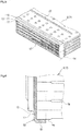
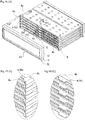
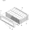
- the external frame portions 10 of a pair of the frame bodies 13 are fitted onto both ends on the bulging portion 4 side of the stacked body 8, the frame bodies 13 grasp outer peripheries of both end portions of the stacked body 8, the casing 9 is fitted onto outer peripheries of the external frame portions 10 of the frame bodies 13, and, between the packing grasping portion 12 of the frame body 13 and both end edges of the casing 9, the annular groove 14 into which a packing for seal can be inserted is formed.
- both end portions of the stacked body 8 of flat tubes 7 are integrally brought together by a pair of the frame bodies 13, and, in the state, the casing 9 is fitted onto the outer periphery of the external frame portion 10 of the frame body 13, and therefore the assembling of a heat exchanger core before brazing can be performed easily and precisely. Then, in a state where respective components are restrained one another, brazing can be performed quickly and easily.
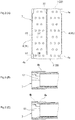
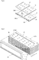
- Figs. 4 - 7 illustrate a temporarily assembled structure before brazing of a heat exchanger core of the present invention.
- a width shrinking part 16 shrunk at both ends in the side wall direction of a pair of the side walls 1 and 2 is formed, and, there, a step part 30 is formed in a stepped shape on an inner side by the magnitude of thickness .
- edge parts of a pair of the side wall 1 and side wall 2 of the plate 5 on the other side are seated.
- the frame body 13 has an external frame portion 10 whose inner periphery matches with the outer periphery of the stacked body 8, an inside flange portion 11 bent inward from the edge part of the external frame portion 10, and a packing holding portion 12 extended upward, outward from an inner peripheral edge of the inside flange portion 11 and extends in the side wall direction.
- the external frame portion 10 of the frame body 13 is fitted onto the width wide portion 4a of the bulging portion 4 of the stacked body 8 to improve the reliability of brazing, in particular, at the corner portion of the stacked body 8.
- the contact part of the width wide portion 4a gives a large contact area thereof to improve the strength of the brazing between the flat tubes 7.
- the external frame portion 10 of the frame body 13 surely holds the width wide portion 4a at the corner portion of the stacked body 8, and the brazing between the width wide portion 4a and the frame body 13 is performed surely.
- the contact length between the width wide portions 4a is set, preferably, to be slightly longer than the length of the external frame portion 10.
- the stacked body 8 is stacked in the state where the side wall 1 sides having the first fitting structure 28 of the flat tube 7 have been adjusted, and, therefore, one side of the side wall 1 has an "M-like” shape and the other side of the side wall 2 has a "mountain-like” shape.
- annular groove 14 into which a packing for seal can be inserted is formed among a packing grasping portion 12 of the frame body 13, the inside flange portion 11, and inner walls of both end edges of the casing 9. Then, a packing 23 is arranged to the annular groove 14, and, subsequently, a pair of a tank 24 and tank 25 are fitted.
- each slit 22 provided for both opening ends of the heat exchanger core 15 is caulked to fix the casing 9 and the tank 24, and the casing 9 and the tank 25 by a caulk part 26.
- the tank 24 and the tank 25 are composed of AL cast.
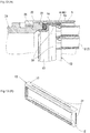
- Fig. 13 shows a modified example of the frame body 13 for use in the present invention, in which (A) is a main part longitudinal cross-sectional view, and (B) illustrates a perspective view of the frame body 13.
- the inner volume of the external frame portion 10 is expanded to smoothly circulate a fluid from the tank 25 to each stacked body 8.
- the space between the external frame portion 10 and the plate of the flat tube 7 on the outermost side is set to be equal to the thickness of the external frame portion 10. Then, the partition portion 27a of the casing 9 and the partition portion 27 of the plate of the flat tube 7 on the outermost side are closely attached to each other, to cause a fluid circulating around the partition to circulate smoothly in a U-like shape.
- Fig. 15 illustrates a modified example of the flat tube 7 for use in the present invention, and the stacked body 8 is configured using the flat tube 7.
- an end tongue piece portion 4c protrudes from the tip of the width wide portion 4a of each of the plates 5 and 6 toward the side wall direction.
- the end tongue piece portion 4c is provided in a protruding state in approximately L-like shape in a state of including a part of each of the side walls 1 and 2.
- a middle protruding portion 4d is protruded in the side wall direction at a middle position in the longitudinal direction of the width narrow portion 4b.
- the length of each end tongue piece portion 4c and the protruding length of the middle protruding portion 4d are set to be approximately identical.
- a material quality of the tank is not limited and, for example, a tank may be an injection molded article of resin.
- the dimple 18 provided on the outer surface of the flat tube 7 in this Example may be omitted.
- a caulked structure of a tank and a heat exchanger core may be a structure performed by providing a number of caulking claws for an opening end of a heat exchanger core and bending these toward the tank side, in place of a structure performed by the slit 22.
Landscapes
- Engineering & Computer Science (AREA)
- Physics & Mathematics (AREA)
- Thermal Sciences (AREA)
- Mechanical Engineering (AREA)
- General Engineering & Computer Science (AREA)
- Geometry (AREA)
- Heat-Exchange Devices With Radiators And Conduit Assemblies (AREA)
Claims (11)
- Structure d'un noyau d'échangeur de chaleur sans plaque de collecteur, dans laquelle :une paire de plaques (5, 6) ayant une paire de parois latérales (1, 2) étendues vers le haut des deux côtés, respectivement, pour former un corps entier en une forme de rainure, et des parties bombées (4) formées au niveau de bords des deux côtés ouverts d'un fond de rainure (3) sur un côté extérieur dans une direction d'épaisseur orthogonalement aux parois latérales (1, 2) sont ajustées les uns par rapport autres en se faisant face dans une direction inverse, pour former ainsi un tube plat (7) ; etun carter (9) est ajusté sur une périphérie extérieure d'un corps empilé (8) configuré en empilant une pluralité des tubes plats (7) les uns sur les autres au niveau des parties bombées(4), dans laquelle :une partie de cadre externe (10) dont une périphérie intérieure correspond à une périphérie extérieure sur un côté de partie bombée (4) du corps empilé (8), une partie de bride intérieure (11) formée au niveau d'un bord périphérique de la partie de cadre externe (10) et une partie de maintien de garniture (12) étendue vers le haut dans une direction de paroi latérale au niveau d'un bord intérieur de la partie de bride intérieure (11) constituent un corps de cadre (13) ; caractérisée en ce queles parties de cadre externes (10) d'une paire des corps de cadre (13) sont montées sur les deux extrémités sur un côté de partie bombée (4) du corps empilé (8) pour saisir des périphéries extérieures au niveau des deux parties d'extrémité du corps empilé (8) avec le corps de cadre (13), et le cadre (9) est ajusté sur une périphérie extérieure de la partie de cadre externe (10) du corps de cadre (13) ; eten résultat, une rainure annulaire (14) dans laquelle une garniture d'étanchéité peut être insérée est formée entre une partie de préhension de garniture (12) du corps de cadre (13) et les deux bords d'extrémité du carter (9).
- Structure du noyau d'échangeur de chaleur sans plaque de collecteur selon la revendication 1, dans laquelle la partie bombée (4) de chacune de la paire de plaques (5, 6) comprend :des parties de largeur large (4a) situées au niveau des deux parties d'extrémité dans une direction longitudinale de la partie bombée (4), avec une largeur large dans la direction de paroi latérale ; etune partie de largeur étroite (4b) située entre les parties de largeur large (4a), avec une largeur étroite de celle-ci.
- Structure du noyau d'échangeur de chaleur sans plaque de collecteur selon la revendication 2, dans laquelle une longueur dans une direction de paroi latérale de la partie de largeur large (4a) de la partie bombée (4) est plus longue qu'une largeur dans une direction de paroi latérale de la partie de cadre externe (10) du corps de cadre (13).
- Structure d'un noyau d'échangeur de chaleur sans plaque de collecteur selon l'une quelconque des revendications 1 à 3, dans laquelle :entre une paire des parties bombées (4) sur un côté de face extérieure du tube plat (7) est formée une partie de séparation (27) qui est parallèle à la partie bombée(4) et a la même hauteur que la partie bombée (4) ;la partie de séparation (27) est formée de manière à atteindre un bord d'un premier côté de la paroi latérale (1), et à ne pas atteindre l'autre côté de la paroi latérale (2) mais à se terminer sur ce côté de la paroi latérale (2), et est formée de sorte qu'un premier fluide (32) sur un côté de face extérieure du tube plat (7) se présente sous la forme d'un U autour de la partie de séparation (27) ; etdans le tube plat (7), une première structure d'ajustement (28) entre les parois latérales (1) sur un premier côté de la paire de plaques (5, 6) composant le tube plat (7) est différente d'une seconde structure d'ajustement 29) entre les parois latérales (2) sur l'autre côté pour éviter un décalage tel qu'un premier côté de la paroi latérale (1) soit combiné avec l'autre côté de la paroi latérale (2).
- Structure du noyau d'échangeur de chaleur sans plaque de collecteur selon la revendication 4, dans laquelle la première structure d'ajustement (28) entre les parois latérales (1) sur un premier côté est formée faisant saillie en une forme de M légèrement vers l'extérieur dans une vue de dessus, et la seconde structure d'ajustement (29) entre les parois latérales (2) sur l'autre côté est formée faisant saillie en une forme de montagne légèrement vers l'extérieur dans une vue de dessus.
- Structure du noyau d'échangeur de chaleur sans plaque de collecteur selon l'une quelconque des revendications 1 à 5, dans laquelle la partie de cadre externe (10) du corps de cadre (13) est prolongée dans la direction de paroi latérale et une partie convexe (34) pour une bitée est formée sur une périphérie intérieure de la partie de cadre externe (10), et le corps empilé (8) est positionné au niveau de la partie convexe (34).
- Structure du noyau d'échangeur de chaleur sans plaque de collecteur selon l'une quelconque des revendications 1 à 5, dans laquelle la structure est configurée pour avoir une partie de pièce de languette d'extrémité (4c) faisant saillie dans la direction de paroi latérale à partir de pointes des deux parties d'extrémité dans une direction longitudinale de la partie bombée (4) de chacune de la paire de plaques (5, 6), pour amener une pointe de la partie de pièce de languette d'extrémité (4c) à venir en butée contre la partie de bride intérieure (11) pour former ainsi un espace (36) entre la partie bombée (4) et la partie de bride intérieure (11), et pour conduire en douceur un second fluide (33) vers une ouverture de chaque tube plat (7) .
- Structure du noyau d'échangeur de chaleur sans plaque de collecteur selon la revendication 7, dans laquelle, dans une position médiane dans une direction longitudinale de la partie bombée (4), une partie médiane faisant saillie (4d) fait saillie dans la direction de paroi latérale, et le la partie médiane faisant saillie (4d) vient en butée sur la partie de bride intérieure (11).
- Structure du noyau d'échangeur de chaleur sans plaque de collecteur selon la revendication 7, dans laquelle la partie convexe (34) pour une butée est formée uniquement sur une périphérie intérieure d'un site correspondant à une partie médiane dans une direction longitudinale de la partie bombée (4) du tube plat (7) dans la partie de cadre externe (10) du corps de cadre (13) et, sur la partie convexe (34), la partie médiane est mise en butée dans une direction longitudinale de la partie bombée (4) du tube plat (7).
- Structure du noyau d'échangeur de chaleur sans plaque de collecteur selon l'une quelconque des revendications 1 à 9, dans laquelle une périphérie extérieure d'une partie d'extrémité du carter (9) a une partie d'extrémité d'expansion (35) expansée vers l'extérieur en une forme étagée, la partie d'extrémité d'expansion (35) est ajustée sur une périphérie extérieure de la partie de cadre externe (10) et, à l'exclusion de la partie d'extrémité d'expansion (35), un espace entre une face intérieure du carter (9) et une plaque reposant sur le côté le plus à l'extérieur dans une direction d'empilement du corps empilé (8) est maintenu à une épaisseur de la partie de cadre externe (10) .
- Structure d'un noyau d'échangeur de chaleur sans plaque de collecteur selon l'une quelconque des revendications 1 à 10, dans laquelle des composants respectifs sont brasés en une seule pièce dans un four haute température.
Applications Claiming Priority (2)
| Application Number | Priority Date | Filing Date | Title |
|---|---|---|---|
| JP2015213109 | 2015-10-29 | ||
| PCT/JP2016/082193 WO2017073779A1 (fr) | 2015-10-29 | 2016-10-21 | Structure de noyau d'échangeur de chaleur sans plaque de collecteur |
Publications (3)
| Publication Number | Publication Date |
|---|---|
| EP3370028A1 EP3370028A1 (fr) | 2018-09-05 |
| EP3370028A4 EP3370028A4 (fr) | 2019-06-12 |
| EP3370028B1 true EP3370028B1 (fr) | 2020-07-08 |
Family
ID=58630426
Family Applications (1)
| Application Number | Title | Priority Date | Filing Date |
|---|---|---|---|
| EP16860007.0A Active EP3370028B1 (fr) | 2015-10-29 | 2016-10-21 | Structure de noyau d'échangeur de chaleur sans plaque de collecteur |
Country Status (5)
| Country | Link |
|---|---|
| US (1) | US10634431B2 (fr) |
| EP (1) | EP3370028B1 (fr) |
| JP (1) | JP6711841B2 (fr) |
| CN (3) | CN108351187B (fr) |
| WO (1) | WO2017073779A1 (fr) |
Families Citing this family (16)
| Publication number | Priority date | Publication date | Assignee | Title |
|---|---|---|---|---|
| DE102015010885A1 (de) * | 2015-08-20 | 2017-02-23 | Modine Manufacturing Company | Wärmetauscher und Herstellungsverfahren |
| US20190063849A1 (en) * | 2017-08-25 | 2019-02-28 | Hanon Systems | U-shaped housing and cover concept for plate fin heat exchangers |
| FR3075343B1 (fr) * | 2017-12-15 | 2020-01-10 | Faurecia Systemes D'echappement | Dispositif de recuperation de chaleur et procede de fabrication correspondant |
| WO2019131571A1 (fr) * | 2017-12-27 | 2019-07-04 | 株式会社ティラド | Échangeur de chaleur du type dépourvu de plaques du collecteur |
| WO2019131569A1 (fr) * | 2017-12-27 | 2019-07-04 | 株式会社ティラド | Échangeur de chaleur du type dépourvu de plaques du collecteur |
| JP7010715B2 (ja) * | 2018-01-29 | 2022-02-10 | 株式会社ティラド | 熱交換器用タンクの接続構造 |
| US10465992B2 (en) | 2018-03-16 | 2019-11-05 | Hamilton Sundstrand Corporation | Parting sheet in heat exchanger core |
| DE112019000761T5 (de) * | 2018-03-30 | 2020-11-12 | T.Rad Co., Ltd. | Headerplattenloser wärmetauscher |
| JP2019190754A (ja) * | 2018-04-26 | 2019-10-31 | 株式会社デンソー | 熱交換器 |
| JP7244251B2 (ja) * | 2018-10-19 | 2023-03-22 | 株式会社ティラド | 積層型熱交換器 |
| US11316216B2 (en) * | 2018-10-24 | 2022-04-26 | Dana Canada Corporation | Modular heat exchangers for battery thermal modulation |
| CN111509325A (zh) * | 2019-01-30 | 2020-08-07 | 达纳加拿大公司 | 具有多通道流体流动通路的热交换器 |
| CN111721149A (zh) * | 2019-03-20 | 2020-09-29 | 杭州三花研究院有限公司 | 一种换热器 |
| JP7247717B2 (ja) * | 2019-04-01 | 2023-03-29 | 株式会社デンソー | 熱交換器 |
| JP7349821B2 (ja) * | 2019-06-10 | 2023-09-25 | 株式会社ティラド | 熱交換器 |
| CN111692899B (zh) * | 2019-08-28 | 2022-05-13 | 浙江三花智能控制股份有限公司 | 换热器及其制造方法 |
Family Cites Families (40)
| Publication number | Priority date | Publication date | Assignee | Title |
|---|---|---|---|---|
| FR2503346B2 (fr) * | 1980-11-24 | 1986-02-21 | Chausson Usines Sa | Echangeur de chaleur assemble mecaniquement du type a tubes et ailettes |
| US4681155A (en) * | 1986-05-01 | 1987-07-21 | The Garrett Corporation | Lightweight, compact heat exchanger |
| GB2343643B (en) * | 1998-11-10 | 2002-01-16 | Centrax Ltd | Heat exchanger |
| CN2575590Y (zh) * | 2002-10-28 | 2003-09-24 | 刘雲生 | 吸附型密封板式换热器 |
| JP4324925B2 (ja) * | 2004-09-28 | 2009-09-02 | 株式会社ティラド | 熱交換器 |
| US7195060B2 (en) * | 2005-04-01 | 2007-03-27 | Dana Canada Corporation | Stacked-tube heat exchanger |
| WO2007031306A1 (fr) | 2005-09-16 | 2007-03-22 | Behr Gmbh & Co. Kg | Echangeur de chaleur, notamment echangeur de chaleur de gaz d'echappement de vehicules automobiles |
| WO2007048603A2 (fr) * | 2005-10-26 | 2007-05-03 | Behr Gmbh & Co. Kg | Echangeur de chaleur et procede de fabrication d'un echangeur de chaleur |
| US9127895B2 (en) * | 2006-01-23 | 2015-09-08 | MAHLE Behr GmbH & Co. KG | Heat exchanger |
| BRPI0807410A2 (pt) * | 2007-01-23 | 2014-05-27 | Modine Mfg Co | Trocador de calor e método |
| US8240391B2 (en) | 2007-05-09 | 2012-08-14 | Frank's Casing Crew And Rental Tools, Inc. | Single joint elevator with gripping jaws and method of hoisting a tubular member |
| JP2009063223A (ja) * | 2007-09-06 | 2009-03-26 | Denso Corp | 熱交換器 |
| FR2933178A1 (fr) * | 2008-06-26 | 2010-01-01 | Valeo Systemes Thermiques | Echangeur de chaleur et carter pour l'echangeur |
| FR2933177B1 (fr) * | 2008-06-26 | 2018-05-25 | Valeo Systemes Thermiques Branche Thermique Moteur | Echangeur de chaleur et carter pour l'echangeur |
| KR100909490B1 (ko) * | 2008-07-09 | 2009-07-28 | (주)신한아펙스 | 열교환기용 전열쉘, 전열조립체 및 이들의 제조방법 |
| JP2010048536A (ja) * | 2008-08-25 | 2010-03-04 | Denso Corp | 熱交換器 |
| US20100224173A1 (en) * | 2009-03-09 | 2010-09-09 | Herve Palanchon | Heat Exchanger with Cast Housing and Method of Making Same |
| JP5321271B2 (ja) | 2009-06-17 | 2013-10-23 | 株式会社デンソー | 高温ガス冷却用熱交換器 |
| JP5486239B2 (ja) * | 2009-08-18 | 2014-05-07 | 株式会社ティラド | ヘッダプレートレス型の熱交換器 |
| FR2954481B1 (fr) * | 2009-12-18 | 2012-02-03 | Valeo Systemes Thermiques | Echangeur de chaleur |
| AU2011201083B2 (en) * | 2010-03-18 | 2013-12-05 | Modine Manufacturing Company | Heat exchanger and method of manufacturing the same |
| JP5533715B2 (ja) * | 2010-04-09 | 2014-06-25 | 株式会社デンソー | 排気熱交換装置 |
| FR2968753B1 (fr) * | 2010-12-10 | 2012-12-21 | Valeo Systemes Thermiques | Echangeur de chaleur, notamment pour vehicule automobile |
| JP5585558B2 (ja) * | 2011-09-24 | 2014-09-10 | 株式会社デンソー | 排気熱交換装置 |
| WO2013059941A1 (fr) * | 2011-10-28 | 2013-05-02 | Dana Canada Corporation | Refroidisseur d'air de suralimentation à écoulement divisé et à rebords surbaissés, doté d'un collecteur de sortie d'écoulement uniforme |
| CN103090713B (zh) * | 2011-11-07 | 2016-03-02 | 株式会社T.Rad | 热交换器 |
| JP6109473B2 (ja) * | 2011-11-30 | 2017-04-05 | 東京ラヂエーター製造株式会社 | Egrクーラ |
| DE102012204121A1 (de) * | 2012-03-15 | 2013-09-19 | Mahle International Gmbh | Ladeluftkühleinrichtung |
| DE102012206989A1 (de) * | 2012-04-26 | 2013-10-31 | Behr Gmbh & Co. Kg | Rohrboden eines Wärmeübertragers |
| DE102012211857A1 (de) | 2012-07-06 | 2014-01-09 | Behr Gmbh & Co. Kg | Wärmeübertrager |
| JP6000769B2 (ja) | 2012-09-12 | 2016-10-05 | 株式会社ティラド | ヘッダプレートレス熱交換器のタンク接続構造 |
| JP2014081175A (ja) * | 2012-10-18 | 2014-05-08 | T Rad Co Ltd | 排気熱交換器のケーシング接続構造 |
| FR2997485B1 (fr) * | 2012-10-25 | 2018-09-14 | Valeo Systemes Thermiques | Echangeur thermique, notamment pour vehicule automobile |
| JP6276054B2 (ja) * | 2013-06-21 | 2018-02-07 | 株式会社ティラド | 熱交換器 |
| JP5989619B2 (ja) * | 2013-09-13 | 2016-09-07 | 株式会社ティラド | ヘッダープレートレス熱交換器のタンク構造 |
| JP6341530B2 (ja) | 2013-11-01 | 2018-06-13 | 臼井国際産業株式会社 | 多管式熱交換器 |
| CN104896990A (zh) * | 2014-03-05 | 2015-09-09 | 株式会社T.Rad | 无联箱板换热器的罐连接构造 |
| JP6296837B2 (ja) | 2014-03-07 | 2018-03-20 | 株式会社ティラド | タンクのシール構造 |
| DE102014219093A1 (de) * | 2014-09-22 | 2016-03-24 | Mahle International Gmbh | Wärmetauscher |
| JP6906234B2 (ja) * | 2018-07-05 | 2021-07-21 | 株式会社ヤエス | 昇降式入浴装置 |
-
2016
- 2016-10-21 JP JP2017547917A patent/JP6711841B2/ja active Active
- 2016-10-21 CN CN201680062874.7A patent/CN108351187B/zh active Active
- 2016-10-21 CN CN201910988916.5A patent/CN110686539B/zh active Active
- 2016-10-21 CN CN201910988466.XA patent/CN110686538B/zh active Active
- 2016-10-21 WO PCT/JP2016/082193 patent/WO2017073779A1/fr not_active Ceased
- 2016-10-21 EP EP16860007.0A patent/EP3370028B1/fr active Active
- 2016-10-21 US US15/770,663 patent/US10634431B2/en active Active
Also Published As
| Publication number | Publication date |
|---|---|
| CN110686538B (zh) | 2021-01-08 |
| JP6711841B2 (ja) | 2020-06-17 |
| CN108351187B (zh) | 2020-04-14 |
| US20180320975A1 (en) | 2018-11-08 |
| WO2017073779A1 (fr) | 2017-05-04 |
| EP3370028A4 (fr) | 2019-06-12 |
| CN110686538A (zh) | 2020-01-14 |
| CN110686539B (zh) | 2020-11-20 |
| EP3370028A1 (fr) | 2018-09-05 |
| CN108351187A (zh) | 2018-07-31 |
| JPWO2017073779A1 (ja) | 2018-08-16 |
| CN110686539A (zh) | 2020-01-14 |
| US10634431B2 (en) | 2020-04-28 |
Similar Documents
| Publication | Publication Date | Title |
|---|---|---|
| EP3370028A1 (fr) | Structure de noyau d'échangeur de chaleur sans plaque de collecteur | |
| EP3045850B1 (fr) | Structure de réservoir pour échangeur de chaleur sans plaque collectrice | |
| JP6796074B2 (ja) | 熱交換器およびその組立て方法 | |
| JP6276054B2 (ja) | 熱交換器 | |
| US20150377560A1 (en) | Manifold, in particular for use in a cooler of a cooling system | |
| EP3045853A1 (fr) | Structure de réservoir pour échangeur de chaleur sans plaque collectrice | |
| JP6000769B2 (ja) | ヘッダプレートレス熱交換器のタンク接続構造 | |
| JP2018518649A (ja) | 熱交換器、及び、当該熱交換器を製造するための対応する方法 | |
| US10598444B2 (en) | Heat exchanger | |
| JP6938669B2 (ja) | 自動車両用の熱交換器 | |
| JP2008211147A (ja) | 熱交換器のパイプ取付け構造 | |
| CN104896990A (zh) | 无联箱板换热器的罐连接构造 | |
| JP2015121334A (ja) | ヘッダプレートレス型熱交換器 | |
| JP6583071B2 (ja) | タンク、および熱交換器 | |
| JP4235940B2 (ja) | 熱交換器の製造方法および熱交換器 | |
| CN116261512A (zh) | 用于控制部件温度的装置和用于制造该装置的方法 | |
| JP6325960B2 (ja) | 熱交換器およびその製造方法 | |
| JPH0640684U (ja) | 熱交換器 | |
| US11746812B2 (en) | Dual component sealing fastener and coupling assembly including same | |
| JP6276114B2 (ja) | ヘッダプレートレス熱交換器用偏平チューブ | |
| JP4360977B2 (ja) | 熱交換器 | |
| KR20160090700A (ko) | 적층식 판형 열교환기 | |
| WO2016152127A1 (fr) | Réservoir et échangeur de chaleur | |
| EP3176531A1 (fr) | Tube plat pour échangeur de chaleur sans plaque collectrice | |
| JP2017116202A (ja) | 熱交換器 |
Legal Events
| Date | Code | Title | Description |
|---|---|---|---|
| STAA | Information on the status of an ep patent application or granted ep patent |
Free format text: STATUS: THE INTERNATIONAL PUBLICATION HAS BEEN MADE |
|
| PUAI | Public reference made under article 153(3) epc to a published international application that has entered the european phase |
Free format text: ORIGINAL CODE: 0009012 |
|
| STAA | Information on the status of an ep patent application or granted ep patent |
Free format text: STATUS: REQUEST FOR EXAMINATION WAS MADE |
|
| 17P | Request for examination filed |
Effective date: 20180319 |
|
| AK | Designated contracting states |
Kind code of ref document: A1 Designated state(s): AL AT BE BG CH CY CZ DE DK EE ES FI FR GB GR HR HU IE IS IT LI LT LU LV MC MK MT NL NO PL PT RO RS SE SI SK SM TR |
|
| AX | Request for extension of the european patent |
Extension state: BA ME |
|
| DAV | Request for validation of the european patent (deleted) | ||
| DAX | Request for extension of the european patent (deleted) | ||
| A4 | Supplementary search report drawn up and despatched |
Effective date: 20190513 |
|
| RIC1 | Information provided on ipc code assigned before grant |
Ipc: F28D 1/047 20060101ALI20190507BHEP Ipc: F28F 1/02 20060101ALI20190507BHEP Ipc: F28F 9/02 20060101AFI20190507BHEP |
|
| GRAP | Despatch of communication of intention to grant a patent |
Free format text: ORIGINAL CODE: EPIDOSNIGR1 |
|
| STAA | Information on the status of an ep patent application or granted ep patent |
Free format text: STATUS: GRANT OF PATENT IS INTENDED |
|
| INTG | Intention to grant announced |
Effective date: 20200123 |
|
| GRAS | Grant fee paid |
Free format text: ORIGINAL CODE: EPIDOSNIGR3 |
|
| GRAA | (expected) grant |
Free format text: ORIGINAL CODE: 0009210 |
|
| STAA | Information on the status of an ep patent application or granted ep patent |
Free format text: STATUS: THE PATENT HAS BEEN GRANTED |
|
| AK | Designated contracting states |
Kind code of ref document: B1 Designated state(s): AL AT BE BG CH CY CZ DE DK EE ES FI FR GB GR HR HU IE IS IT LI LT LU LV MC MK MT NL NO PL PT RO RS SE SI SK SM TR |
|
| REG | Reference to a national code |
Ref country code: CH Ref legal event code: EP Ref country code: AT Ref legal event code: REF Ref document number: 1288916 Country of ref document: AT Kind code of ref document: T Effective date: 20200715 |
|
| REG | Reference to a national code |
Ref country code: DE Ref legal event code: R096 Ref document number: 602016039758 Country of ref document: DE |
|
| REG | Reference to a national code |
Ref country code: IE Ref legal event code: FG4D |
|
| REG | Reference to a national code |
Ref country code: LT Ref legal event code: MG4D |
|
| REG | Reference to a national code |
Ref country code: AT Ref legal event code: MK05 Ref document number: 1288916 Country of ref document: AT Kind code of ref document: T Effective date: 20200708 |
|
| REG | Reference to a national code |
Ref country code: NL Ref legal event code: MP Effective date: 20200708 |
|
| PG25 | Lapsed in a contracting state [announced via postgrant information from national office to epo] |
Ref country code: ES Free format text: LAPSE BECAUSE OF FAILURE TO SUBMIT A TRANSLATION OF THE DESCRIPTION OR TO PAY THE FEE WITHIN THE PRESCRIBED TIME-LIMIT Effective date: 20200708 Ref country code: GR Free format text: LAPSE BECAUSE OF FAILURE TO SUBMIT A TRANSLATION OF THE DESCRIPTION OR TO PAY THE FEE WITHIN THE PRESCRIBED TIME-LIMIT Effective date: 20201009 Ref country code: NO Free format text: LAPSE BECAUSE OF FAILURE TO SUBMIT A TRANSLATION OF THE DESCRIPTION OR TO PAY THE FEE WITHIN THE PRESCRIBED TIME-LIMIT Effective date: 20201008 Ref country code: PT Free format text: LAPSE BECAUSE OF FAILURE TO SUBMIT A TRANSLATION OF THE DESCRIPTION OR TO PAY THE FEE WITHIN THE PRESCRIBED TIME-LIMIT Effective date: 20201109 Ref country code: LT Free format text: LAPSE BECAUSE OF FAILURE TO SUBMIT A TRANSLATION OF THE DESCRIPTION OR TO PAY THE FEE WITHIN THE PRESCRIBED TIME-LIMIT Effective date: 20200708 Ref country code: AT Free format text: LAPSE BECAUSE OF FAILURE TO SUBMIT A TRANSLATION OF THE DESCRIPTION OR TO PAY THE FEE WITHIN THE PRESCRIBED TIME-LIMIT Effective date: 20200708 Ref country code: BG Free format text: LAPSE BECAUSE OF FAILURE TO SUBMIT A TRANSLATION OF THE DESCRIPTION OR TO PAY THE FEE WITHIN THE PRESCRIBED TIME-LIMIT Effective date: 20201008 Ref country code: FI Free format text: LAPSE BECAUSE OF FAILURE TO SUBMIT A TRANSLATION OF THE DESCRIPTION OR TO PAY THE FEE WITHIN THE PRESCRIBED TIME-LIMIT Effective date: 20200708 Ref country code: HR Free format text: LAPSE BECAUSE OF FAILURE TO SUBMIT A TRANSLATION OF THE DESCRIPTION OR TO PAY THE FEE WITHIN THE PRESCRIBED TIME-LIMIT Effective date: 20200708 Ref country code: SE Free format text: LAPSE BECAUSE OF FAILURE TO SUBMIT A TRANSLATION OF THE DESCRIPTION OR TO PAY THE FEE WITHIN THE PRESCRIBED TIME-LIMIT Effective date: 20200708 |
|
| PG25 | Lapsed in a contracting state [announced via postgrant information from national office to epo] |
Ref country code: LV Free format text: LAPSE BECAUSE OF FAILURE TO SUBMIT A TRANSLATION OF THE DESCRIPTION OR TO PAY THE FEE WITHIN THE PRESCRIBED TIME-LIMIT Effective date: 20200708 Ref country code: RS Free format text: LAPSE BECAUSE OF FAILURE TO SUBMIT A TRANSLATION OF THE DESCRIPTION OR TO PAY THE FEE WITHIN THE PRESCRIBED TIME-LIMIT Effective date: 20200708 Ref country code: PL Free format text: LAPSE BECAUSE OF FAILURE TO SUBMIT A TRANSLATION OF THE DESCRIPTION OR TO PAY THE FEE WITHIN THE PRESCRIBED TIME-LIMIT Effective date: 20200708 Ref country code: IS Free format text: LAPSE BECAUSE OF FAILURE TO SUBMIT A TRANSLATION OF THE DESCRIPTION OR TO PAY THE FEE WITHIN THE PRESCRIBED TIME-LIMIT Effective date: 20201108 |
|
| PG25 | Lapsed in a contracting state [announced via postgrant information from national office to epo] |
Ref country code: NL Free format text: LAPSE BECAUSE OF FAILURE TO SUBMIT A TRANSLATION OF THE DESCRIPTION OR TO PAY THE FEE WITHIN THE PRESCRIBED TIME-LIMIT Effective date: 20200708 |
|
| REG | Reference to a national code |
Ref country code: DE Ref legal event code: R097 Ref document number: 602016039758 Country of ref document: DE |
|
| PG25 | Lapsed in a contracting state [announced via postgrant information from national office to epo] |
Ref country code: IT Free format text: LAPSE BECAUSE OF FAILURE TO SUBMIT A TRANSLATION OF THE DESCRIPTION OR TO PAY THE FEE WITHIN THE PRESCRIBED TIME-LIMIT Effective date: 20200708 Ref country code: EE Free format text: LAPSE BECAUSE OF FAILURE TO SUBMIT A TRANSLATION OF THE DESCRIPTION OR TO PAY THE FEE WITHIN THE PRESCRIBED TIME-LIMIT Effective date: 20200708 Ref country code: SM Free format text: LAPSE BECAUSE OF FAILURE TO SUBMIT A TRANSLATION OF THE DESCRIPTION OR TO PAY THE FEE WITHIN THE PRESCRIBED TIME-LIMIT Effective date: 20200708 Ref country code: RO Free format text: LAPSE BECAUSE OF FAILURE TO SUBMIT A TRANSLATION OF THE DESCRIPTION OR TO PAY THE FEE WITHIN THE PRESCRIBED TIME-LIMIT Effective date: 20200708 Ref country code: DK Free format text: LAPSE BECAUSE OF FAILURE TO SUBMIT A TRANSLATION OF THE DESCRIPTION OR TO PAY THE FEE WITHIN THE PRESCRIBED TIME-LIMIT Effective date: 20200708 Ref country code: CZ Free format text: LAPSE BECAUSE OF FAILURE TO SUBMIT A TRANSLATION OF THE DESCRIPTION OR TO PAY THE FEE WITHIN THE PRESCRIBED TIME-LIMIT Effective date: 20200708 |
|
| PLBE | No opposition filed within time limit |
Free format text: ORIGINAL CODE: 0009261 |
|
| STAA | Information on the status of an ep patent application or granted ep patent |
Free format text: STATUS: NO OPPOSITION FILED WITHIN TIME LIMIT |
|
| PG25 | Lapsed in a contracting state [announced via postgrant information from national office to epo] |
Ref country code: AL Free format text: LAPSE BECAUSE OF FAILURE TO SUBMIT A TRANSLATION OF THE DESCRIPTION OR TO PAY THE FEE WITHIN THE PRESCRIBED TIME-LIMIT Effective date: 20200708 |
|
| REG | Reference to a national code |
Ref country code: CH Ref legal event code: PL |
|
| 26N | No opposition filed |
Effective date: 20210409 |
|
| GBPC | Gb: european patent ceased through non-payment of renewal fee |
Effective date: 20201021 |
|
| PG25 | Lapsed in a contracting state [announced via postgrant information from national office to epo] |
Ref country code: SK Free format text: LAPSE BECAUSE OF FAILURE TO SUBMIT A TRANSLATION OF THE DESCRIPTION OR TO PAY THE FEE WITHIN THE PRESCRIBED TIME-LIMIT Effective date: 20200708 Ref country code: MC Free format text: LAPSE BECAUSE OF FAILURE TO SUBMIT A TRANSLATION OF THE DESCRIPTION OR TO PAY THE FEE WITHIN THE PRESCRIBED TIME-LIMIT Effective date: 20200708 Ref country code: LU Free format text: LAPSE BECAUSE OF NON-PAYMENT OF DUE FEES Effective date: 20201021 |
|
| REG | Reference to a national code |
Ref country code: BE Ref legal event code: MM Effective date: 20201031 |
|
| PG25 | Lapsed in a contracting state [announced via postgrant information from national office to epo] |
Ref country code: FR Free format text: LAPSE BECAUSE OF NON-PAYMENT OF DUE FEES Effective date: 20201031 |
|
| PG25 | Lapsed in a contracting state [announced via postgrant information from national office to epo] |
Ref country code: SI Free format text: LAPSE BECAUSE OF FAILURE TO SUBMIT A TRANSLATION OF THE DESCRIPTION OR TO PAY THE FEE WITHIN THE PRESCRIBED TIME-LIMIT Effective date: 20200708 Ref country code: GB Free format text: LAPSE BECAUSE OF NON-PAYMENT OF DUE FEES Effective date: 20201021 Ref country code: LI Free format text: LAPSE BECAUSE OF NON-PAYMENT OF DUE FEES Effective date: 20201031 Ref country code: BE Free format text: LAPSE BECAUSE OF NON-PAYMENT OF DUE FEES Effective date: 20201031 Ref country code: CH Free format text: LAPSE BECAUSE OF NON-PAYMENT OF DUE FEES Effective date: 20201031 |
|
| PG25 | Lapsed in a contracting state [announced via postgrant information from national office to epo] |
Ref country code: IE Free format text: LAPSE BECAUSE OF NON-PAYMENT OF DUE FEES Effective date: 20201021 |
|
| PG25 | Lapsed in a contracting state [announced via postgrant information from national office to epo] |
Ref country code: TR Free format text: LAPSE BECAUSE OF FAILURE TO SUBMIT A TRANSLATION OF THE DESCRIPTION OR TO PAY THE FEE WITHIN THE PRESCRIBED TIME-LIMIT Effective date: 20200708 Ref country code: MT Free format text: LAPSE BECAUSE OF FAILURE TO SUBMIT A TRANSLATION OF THE DESCRIPTION OR TO PAY THE FEE WITHIN THE PRESCRIBED TIME-LIMIT Effective date: 20200708 Ref country code: CY Free format text: LAPSE BECAUSE OF FAILURE TO SUBMIT A TRANSLATION OF THE DESCRIPTION OR TO PAY THE FEE WITHIN THE PRESCRIBED TIME-LIMIT Effective date: 20200708 |
|
| PG25 | Lapsed in a contracting state [announced via postgrant information from national office to epo] |
Ref country code: MK Free format text: LAPSE BECAUSE OF FAILURE TO SUBMIT A TRANSLATION OF THE DESCRIPTION OR TO PAY THE FEE WITHIN THE PRESCRIBED TIME-LIMIT Effective date: 20200708 |
|
| PGFP | Annual fee paid to national office [announced via postgrant information from national office to epo] |
Ref country code: DE Payment date: 20250902 Year of fee payment: 10 |