EP3370056B1 - Appareil de prétraitement et système d'analyse comprenant l'appareil de prétraitement - Google Patents
Appareil de prétraitement et système d'analyse comprenant l'appareil de prétraitement Download PDFInfo
- Publication number
- EP3370056B1 EP3370056B1 EP18000194.3A EP18000194A EP3370056B1 EP 3370056 B1 EP3370056 B1 EP 3370056B1 EP 18000194 A EP18000194 A EP 18000194A EP 3370056 B1 EP3370056 B1 EP 3370056B1
- Authority
- EP
- European Patent Office
- Prior art keywords
- preprocessing
- specimen
- container
- port
- sample
- Prior art date
- Legal status (The legal status is an assumption and is not a legal conclusion. Google has not performed a legal analysis and makes no representation as to the accuracy of the status listed.)
- Active
Links
Images







Classifications
-
- G—PHYSICS
- G01—MEASURING; TESTING
- G01N—INVESTIGATING OR ANALYSING MATERIALS BY DETERMINING THEIR CHEMICAL OR PHYSICAL PROPERTIES
- G01N30/00—Investigating or analysing materials by separation into components using adsorption, absorption or similar phenomena or using ion-exchange, e.g. chromatography or field flow fractionation
- G01N30/02—Column chromatography
- G01N30/04—Preparation or injection of sample to be analysed
- G01N30/06—Preparation
-
- B—PERFORMING OPERATIONS; TRANSPORTING
- B01—PHYSICAL OR CHEMICAL PROCESSES OR APPARATUS IN GENERAL
- B01L—CHEMICAL OR PHYSICAL LABORATORY APPARATUS FOR GENERAL USE
- B01L3/00—Containers or dishes for laboratory use, e.g. laboratory glassware; Droppers
- B01L3/50—Containers for the purpose of retaining a material to be analysed, e.g. test tubes
- B01L3/502—Containers for the purpose of retaining a material to be analysed, e.g. test tubes with fluid transport, e.g. in multi-compartment structures
-
- G—PHYSICS
- G01—MEASURING; TESTING
- G01N—INVESTIGATING OR ANALYSING MATERIALS BY DETERMINING THEIR CHEMICAL OR PHYSICAL PROPERTIES
- G01N1/00—Sampling; Preparing specimens for investigation
- G01N1/28—Preparing specimens for investigation including physical details of (bio-)chemical methods covered elsewhere, e.g. G01N33/50, C12Q
-
- G—PHYSICS
- G01—MEASURING; TESTING
- G01N—INVESTIGATING OR ANALYSING MATERIALS BY DETERMINING THEIR CHEMICAL OR PHYSICAL PROPERTIES
- G01N1/00—Sampling; Preparing specimens for investigation
- G01N1/28—Preparing specimens for investigation including physical details of (bio-)chemical methods covered elsewhere, e.g. G01N33/50, C12Q
- G01N1/40—Concentrating samples
-
- G—PHYSICS
- G01—MEASURING; TESTING
- G01N—INVESTIGATING OR ANALYSING MATERIALS BY DETERMINING THEIR CHEMICAL OR PHYSICAL PROPERTIES
- G01N1/00—Sampling; Preparing specimens for investigation
- G01N1/28—Preparing specimens for investigation including physical details of (bio-)chemical methods covered elsewhere, e.g. G01N33/50, C12Q
- G01N1/40—Concentrating samples
- G01N1/4005—Concentrating samples by transferring a selected component through a membrane
-
- G—PHYSICS
- G01—MEASURING; TESTING
- G01N—INVESTIGATING OR ANALYSING MATERIALS BY DETERMINING THEIR CHEMICAL OR PHYSICAL PROPERTIES
- G01N33/00—Investigating or analysing materials by specific methods not covered by groups G01N1/00 - G01N31/00
- G01N33/48—Biological material, e.g. blood, urine; Haemocytometers
- G01N33/483—Physical analysis of biological material
- G01N33/487—Physical analysis of biological material of liquid biological material
- G01N33/49—Blood
-
- G—PHYSICS
- G01—MEASURING; TESTING
- G01N—INVESTIGATING OR ANALYSING MATERIALS BY DETERMINING THEIR CHEMICAL OR PHYSICAL PROPERTIES
- G01N35/00—Automatic analysis not limited to methods or materials provided for in any single one of groups G01N1/00 - G01N33/00; Handling materials therefor
- G01N35/00584—Control arrangements for automatic analysers
-
- G—PHYSICS
- G01—MEASURING; TESTING
- G01N—INVESTIGATING OR ANALYSING MATERIALS BY DETERMINING THEIR CHEMICAL OR PHYSICAL PROPERTIES
- G01N35/00—Automatic analysis not limited to methods or materials provided for in any single one of groups G01N1/00 - G01N33/00; Handling materials therefor
- G01N35/02—Automatic analysis not limited to methods or materials provided for in any single one of groups G01N1/00 - G01N33/00; Handling materials therefor using a plurality of sample containers moved by a conveyor system past one or more treatment or analysis stations
- G01N35/04—Details of the conveyor system
-
- B—PERFORMING OPERATIONS; TRANSPORTING
- B01—PHYSICAL OR CHEMICAL PROCESSES OR APPARATUS IN GENERAL
- B01L—CHEMICAL OR PHYSICAL LABORATORY APPARATUS FOR GENERAL USE
- B01L2200/00—Solutions for specific problems relating to chemical or physical laboratory apparatus
- B01L2200/06—Fluid handling related problems
- B01L2200/0631—Purification arrangements, e.g. solid phase extraction [SPE]
-
- B—PERFORMING OPERATIONS; TRANSPORTING
- B01—PHYSICAL OR CHEMICAL PROCESSES OR APPARATUS IN GENERAL
- B01L—CHEMICAL OR PHYSICAL LABORATORY APPARATUS FOR GENERAL USE
- B01L2300/00—Additional constructional details
- B01L2300/06—Auxiliary integrated devices, integrated components
- B01L2300/0681—Filter
-
- B—PERFORMING OPERATIONS; TRANSPORTING
- B01—PHYSICAL OR CHEMICAL PROCESSES OR APPARATUS IN GENERAL
- B01L—CHEMICAL OR PHYSICAL LABORATORY APPARATUS FOR GENERAL USE
- B01L2400/00—Moving or stopping fluids
- B01L2400/04—Moving fluids with specific forces or mechanical means
- B01L2400/0475—Moving fluids with specific forces or mechanical means specific mechanical means and fluid pressure
- B01L2400/0487—Moving fluids with specific forces or mechanical means specific mechanical means and fluid pressure fluid pressure, pneumatics
- B01L2400/049—Moving fluids with specific forces or mechanical means specific mechanical means and fluid pressure fluid pressure, pneumatics vacuum
-
- G—PHYSICS
- G01—MEASURING; TESTING
- G01N—INVESTIGATING OR ANALYSING MATERIALS BY DETERMINING THEIR CHEMICAL OR PHYSICAL PROPERTIES
- G01N1/00—Sampling; Preparing specimens for investigation
- G01N1/28—Preparing specimens for investigation including physical details of (bio-)chemical methods covered elsewhere, e.g. G01N33/50, C12Q
- G01N1/40—Concentrating samples
- G01N1/405—Concentrating samples by adsorption or absorption
-
- G—PHYSICS
- G01—MEASURING; TESTING
- G01N—INVESTIGATING OR ANALYSING MATERIALS BY DETERMINING THEIR CHEMICAL OR PHYSICAL PROPERTIES
- G01N1/00—Sampling; Preparing specimens for investigation
- G01N1/28—Preparing specimens for investigation including physical details of (bio-)chemical methods covered elsewhere, e.g. G01N33/50, C12Q
- G01N1/286—Preparing specimens for investigation including physical details of (bio-)chemical methods covered elsewhere, e.g. G01N33/50, C12Q involving mechanical work, e.g. chopping, disintegrating, compacting, homogenising
- G01N2001/2873—Cutting or cleaving
- G01N2001/288—Filter punches
-
- G—PHYSICS
- G01—MEASURING; TESTING
- G01N—INVESTIGATING OR ANALYSING MATERIALS BY DETERMINING THEIR CHEMICAL OR PHYSICAL PROPERTIES
- G01N1/00—Sampling; Preparing specimens for investigation
- G01N1/28—Preparing specimens for investigation including physical details of (bio-)chemical methods covered elsewhere, e.g. G01N33/50, C12Q
- G01N1/40—Concentrating samples
- G01N1/4005—Concentrating samples by transferring a selected component through a membrane
- G01N2001/4011—Concentrating samples by transferring a selected component through a membrane being a ion-exchange membrane
-
- G—PHYSICS
- G01—MEASURING; TESTING
- G01N—INVESTIGATING OR ANALYSING MATERIALS BY DETERMINING THEIR CHEMICAL OR PHYSICAL PROPERTIES
- G01N30/00—Investigating or analysing materials by separation into components using adsorption, absorption or similar phenomena or using ion-exchange, e.g. chromatography or field flow fractionation
- G01N2030/009—Extraction
-
- G—PHYSICS
- G01—MEASURING; TESTING
- G01N—INVESTIGATING OR ANALYSING MATERIALS BY DETERMINING THEIR CHEMICAL OR PHYSICAL PROPERTIES
- G01N30/00—Investigating or analysing materials by separation into components using adsorption, absorption or similar phenomena or using ion-exchange, e.g. chromatography or field flow fractionation
- G01N30/02—Column chromatography
- G01N2030/022—Column chromatography characterised by the kind of separation mechanism
- G01N2030/027—Liquid chromatography
-
- G—PHYSICS
- G01—MEASURING; TESTING
- G01N—INVESTIGATING OR ANALYSING MATERIALS BY DETERMINING THEIR CHEMICAL OR PHYSICAL PROPERTIES
- G01N30/00—Investigating or analysing materials by separation into components using adsorption, absorption or similar phenomena or using ion-exchange, e.g. chromatography or field flow fractionation
- G01N30/02—Column chromatography
- G01N30/04—Preparation or injection of sample to be analysed
- G01N30/06—Preparation
- G01N2030/062—Preparation extracting sample from raw material
-
- G—PHYSICS
- G01—MEASURING; TESTING
- G01N—INVESTIGATING OR ANALYSING MATERIALS BY DETERMINING THEIR CHEMICAL OR PHYSICAL PROPERTIES
- G01N35/00—Automatic analysis not limited to methods or materials provided for in any single one of groups G01N1/00 - G01N33/00; Handling materials therefor
- G01N2035/00465—Separating and mixing arrangements
- G01N2035/00475—Filters
- G01N2035/00485—Filters combined with sample carriers
-
- G—PHYSICS
- G01—MEASURING; TESTING
- G01N—INVESTIGATING OR ANALYSING MATERIALS BY DETERMINING THEIR CHEMICAL OR PHYSICAL PROPERTIES
- G01N35/00—Automatic analysis not limited to methods or materials provided for in any single one of groups G01N1/00 - G01N33/00; Handling materials therefor
- G01N2035/00465—Separating and mixing arrangements
- G01N2035/00524—Mixing by agitating sample carrier
-
- G—PHYSICS
- G01—MEASURING; TESTING
- G01N—INVESTIGATING OR ANALYSING MATERIALS BY DETERMINING THEIR CHEMICAL OR PHYSICAL PROPERTIES
- G01N35/00—Automatic analysis not limited to methods or materials provided for in any single one of groups G01N1/00 - G01N33/00; Handling materials therefor
- G01N35/02—Automatic analysis not limited to methods or materials provided for in any single one of groups G01N1/00 - G01N33/00; Handling materials therefor using a plurality of sample containers moved by a conveyor system past one or more treatment or analysis stations
- G01N35/04—Details of the conveyor system
- G01N2035/0439—Rotary sample carriers, i.e. carousels
- G01N2035/0441—Rotary sample carriers, i.e. carousels for samples
-
- G—PHYSICS
- G01—MEASURING; TESTING
- G01N—INVESTIGATING OR ANALYSING MATERIALS BY DETERMINING THEIR CHEMICAL OR PHYSICAL PROPERTIES
- G01N35/00—Automatic analysis not limited to methods or materials provided for in any single one of groups G01N1/00 - G01N33/00; Handling materials therefor
- G01N35/02—Automatic analysis not limited to methods or materials provided for in any single one of groups G01N1/00 - G01N33/00; Handling materials therefor using a plurality of sample containers moved by a conveyor system past one or more treatment or analysis stations
- G01N35/04—Details of the conveyor system
- G01N2035/0439—Rotary sample carriers, i.e. carousels
- G01N2035/0443—Rotary sample carriers, i.e. carousels for reagents
-
- G—PHYSICS
- G01—MEASURING; TESTING
- G01N—INVESTIGATING OR ANALYSING MATERIALS BY DETERMINING THEIR CHEMICAL OR PHYSICAL PROPERTIES
- G01N35/00—Automatic analysis not limited to methods or materials provided for in any single one of groups G01N1/00 - G01N33/00; Handling materials therefor
- G01N35/10—Devices for transferring samples or any liquids to, in, or from, the analysis apparatus, e.g. suction devices, injection devices
Definitions
- the present invention relates to a preprocessing container for performing preprocessing such as extraction processing for extracting, as a sample, necessary components contained in a living body-derived sample such as whole blood, blood serum, blood plasma, dried blood spot, or urine by removing a specific component unnecessary for analysis from the living body-derived sample, a preprocessing apparatus that automatically performs preprocessing using the preprocessing container, and an analysis system that comprises the preprocessing apparatus and automatically performs a series of processes from preprocessing of a sample to analysis.
- preprocessing container for performing preprocessing such as extraction processing for extracting, as a sample, necessary components contained in a living body-derived sample such as whole blood, blood serum, blood plasma, dried blood spot, or urine by removing a specific component unnecessary for analysis from the living body-derived sample
- preprocessing apparatus that automatically performs preprocessing using the preprocessing container
- an analysis system that comprises the preprocessing apparatus and automatically performs a series of processes from preprocessing of a sample to analysis.
- JP 2010-60474 A discloses that a plurality of cartridges holding a separating agent that separates a specific component by allowing a sample to pass therethrough are held by a common carrying mechanism, these cartridges are sequentially placed in a pressure applying mechanism provided in a predetermined position by the carrying mechanism, and pressure is applied to each of the cartridges in the pressure applying mechanism to perform sample extraction.
- a plurality of extract receivers that receive extracts from the cartridges are moved relative to the cartridges below the cartridges by a carrying mechanism different from the carrying mechanism for cartridges so that the receivers are sequentially placed in the pressure applying mechanism to continuously perform sample extraction.
- the carrying mechanism for cartridges and the carrying mechanism for extract receivers cannot be moved while sample extraction processing is performed in the pressure applying mechanism, and therefore there is a limit to improving preprocessing efficiency. Therefore, the present inventor has proposed that a set of a separation device having a filter for filtering a sample and a collection container for collecting an extracted sample discharged from the separation device is carried in a random access manner to a port where processing such as filtration processing or stirring, processing is performed to improve preprocessing efficiency (see WO 2016/017042 A1 and JP 2016-170079 A ).
- WO 2017/006476 A1 discloses a pretreatment device.
- a container holding unit holds pretreatment containers, into each of which a sample is injected.
- a pretreatment unit sequentially carries out a pretreatment by using, in a fixed order, the pretreatment containers held in holding positions of the container holding unit.
- EP 2 490 019 A1 discloses an examination device and an examination method.
- a solid-phase extraction cartridge or a filter is placed on a continuous track of a cartridge table.
- a cup table is disposed below the cartridge table.
- a cup is placed on a continuous track of the cup table to receive a sample purified by the filter.
- the continuous track of the cartridge table and the continuous track of the cup table cross each other at a position, and each of the tracks crosses a position at which a sample probe operates.
- US 4 859 605 A discloses an automated sample preparation system for chemical assay of samples of materials.
- WO 2016/016109 A2 discloses an arrangement for preparing a plurality of samples for an analytical method.
- the analysis of dried blood spots is generally performed in batch mode by placing dried blood spots in wells of a plate having a plurality of wells, such as a 96-well plate.
- a batch mode analysis is poor in operation efficiency and has high running costs unless a fairly large number of specimens are analyzed.
- specimen management and preprocessing such as reagent dispensing are manually performed, and therefore, problems such as mix-up of specimens and variation in the amount of a reagent dispensed, are likely to occur.
- problems such as mix-up of specimens and variation in the amount of a reagent dispensed, are likely to occur.
- the present invention is directed to a preprocessing apparatus as defined in claim 1.
- the solid sample refers to a sample in which a specimen is held by a solid medium.
- the term "solid medium” refers to a medium having the function of holding a liquid material or a dried and solidified liquid material in or on its membrane, such as filter paper, cotton, gauze, a PTFE (polytetrafluoroethylene) membrane, a nylon membrane, a polypropylene membrane, a PVDF (polyvinylidene fluoride) membrane, an acrylic copolymer membrane, a mixed cellulose membrane, a nitrocellulose membrane, a polyethersulfone membrane, an ion-exchange membrane, or a glass fiber membrane.
- the specimen to be held by such a solid medium include living body-derived specimens such as whole blood, blood serum, urine, and saliva.
- the preprocessing apparatus further comprises a preprocessing operation part that is configured to, when the specimen recognition part recognizes that a specimen to be analyzed is a liquid specimen, allow the carrying mechanism to carry the empty preprocessing container set in the preprocessing container setting part to the dispensing position, allow the specimen dispensing part to dispense the specimen to be analyzed into the preprocessing container, and then allow the carrying mechanism to carry the preprocessing container to the preprocessing part to perform predetermined preprocessing, and that is configured to, when the specimen recognition part recognizes that a specimen to be analyzed is a specimen contained in the solid sample, allow the carrying mechanism to carry the preprocessing container containing the solid sample and set in the preprocessing container setting part to the preprocessing part to perform predetermined preprocessing including the extraction processing.
- a preprocessing operation part that is configured to, when the specimen recognition part recognizes that a specimen to be analyzed is a liquid specimen, allow the carrying mechanism to carry the empty preprocessing container set in the preprocessing container setting part to the dispens
- the preprocessing part has a plurality of extraction ports for performing the extraction processing
- the preprocessing operation part is configured to, when the specimen recognition part recognizes that a specimen to be analyzed is a specimen contained in the solid sample, search the available extraction port and allow the carrying mechanism to carry the target preprocessing container to the available extraction port to perform the extraction processing. This makes it possible to, when there is an available extraction port, carry the preprocessing container to the available extraction port to perform specimen extraction processing in a random access manner, which improves preprocessing efficiency.
- the preprocessing container setting part is configured to allow a plurality of preprocessing containers to be set therein
- the preprocessing apparatus further comprises a solid sample setting information holding part that holds information about a position where the preprocessing container containing the solid sample is set in the preprocessing container setting part and a preprocessing container identification part configured to, when a specimen to be analyzed is a specimen contained in the solid sample, identify the preprocessing container containing the solid sample containing the specimen on a basis of the information held in the solid sample setting information holding part.
- the present invention is also directed to an analysis system comprising: the above-described preprocessing apparatus including a transfer device that has a transfer port where the preprocessing container containing a specimen that has been subjected to preprocessing in the preprocessing part is to be set by the carrying mechanism and that is configured to move the transfer port to transfer the container set in the transfer port to an outside of the preprocessing apparatus; and a liquid chromatographic system that is provided adjacent to the preprocessing apparatus and that has an analytical flow path that allows a mobile phase to flow therethrough, a sample injector that takes, as a sample, the specimen contained in the container moved to the outside of the preprocessing apparatus by the transfer device and injects the sample into the analytical flow path, an analytical column provided on the analytical flow path to separate the sample injected by the sample injector into individual components, and a detector that detects the sample components separated by the analytical column.
- the above-described preprocessing apparatus including a transfer device that has a transfer port where the preprocessing container containing a specimen that has been subjecte
- the preprocessing apparatus comprises: a preprocessing container setting part where a preprocessing container containing a solid sample comprising a specimen to be analyzed and a solid medium holding the specimen is to be set; a carrying mechanism that carries the preprocessing container set in the preprocessing container setting part; and a preprocessing part that has a port for setting the preprocessing container carried by the carrying mechanism and that is configured to perform preprocessing including extraction processing for extracting the specimen from the solid sample contained in the preprocessing container set in the port.
- a specimen can be subjected to preprocessing in the preprocessing apparatus described above, and then the specimen that has been subjected to preprocessing can be automatically introduced into a liquid chromatographic system to be subjected to a separating analysis.
- This makes it possible to fully automatically perform a series of processes from the preprocessing of a specimen contained in a solid sample such as dried blood spot to analysis without human intervention. Since the analysis system is operated without human intervention, errors and variations caused by manual work are eliminated, and therefore the accuracy of analysis results is improved.
- a preprocessing apparatus 1 performs a necessary preprocessing item with the use of a prepared preprocessing container comprising a set of a separation device 50 and a collection container 54 for each specimen.
- the preprocessing apparatus 1 has a plurality of processing ports for performing different preprocessing items, and is configured to allow the preprocessing container containing a specimen to be set in any one of the processing ports to perform a preprocessing item corresponding to the processing port on the specimen contained in the preprocessing container. Each of the processing ports will be described later.
- the preprocessing item refers to the item of preprocessing necessary for performing an analysis item designated by an analyst.
- the separation device 50 and the collection container 54 constituting the preprocessing container are carried by a carrying arm 24 constituting a carrying mechanism.
- the carrying arm 24 has, on its tip side, a holding part 25 for holding the separation device 50 and the collection container 54.
- the base end of the carrying arm 24 is held by a vertical shaft 29, and therefore the carrying arm 24 rotates about the vertical shaft 29 in a horizontal plane so that the holding part 25 draws an arc-shaped track.
- All the processing ports and other ports, to which the separation device 50 and the collection container 54 are to be carried, are provided along the arc-shaped track drawn by the holding part 25.
- a specimen setting part 2 for setting a specimen container 6 containing a liquid specimen is provided, and a sampling arm 20 is provided adjacent to the specimen setting part 2 as a specimen dispensing part for taking the specimen from the specimen container set in the specimen setting part 2.
- a sample rack 4 for holding the specimen containers 6 is annularly provided.
- the specimen setting part 2 rotates in a horizontal plane so as to circumferentially move the sample rack 4, and therefore, a desired one of the specimen containers 6 is placed in a predetermined sampling position by the rotation of the specimen setting part 2.
- the sampling position refers to a position which is along the track of a sampling nozzle 20a provided at the tip of the sampling arm 20 and in which a specimen is taken by the sampling nozzle 20a.
- the sampling arm 20 has a base end through which a vertical shaft 22 passes, and therefore rotates about the shaft 22 in a horizontal plane and moves up and down in a vertical direction along the shaft 22.
- the sampling nozzle 20a is held on the tip side of the sampling arm 20 in such a manner that the tip of the sampling nozzle 20a faces vertically downward, and the sampling nozzle 20a is moved in a horizontal plane so as to draw an arc-shaped track and is moved up and down in a vertical direction by the sampling arm 20.
- a dispensing port 32 is provided in a position on the track of the sampling nozzle 20a and on the track of the holding part 25 of the carrying arm 24.
- the dispensing port 32 is a port where the sampling nozzle 20a dispenses a specimen into the unused separation device 50.
- the unused separation device 50 is set in the dispensing port 32 by the carrying arm 24. Further, the dispensing port 32 is also used to add a reagent to the separation device 50 containing a specimen or to add a reagent to the separation device 50 containing a solid sample that will be described later.
- a reagent setting part 8 for setting a reagent container 10 is provided on the inner side of the specimen setting part 2, and a reagent arm 26 (reagent adding part) for taking a reagent from the reagent container set in the reagent setting part 8 is provided.
- the base end of the reagent arm 26 is supported by the vertical shaft 29 shared with the carrying arm 24, and therefore, the reagent arm 26 rotates in a horizontal plane and moves up and down.
- a probe 27 is provided at the tip of the reagent arm 26.
- the probe 27 is provided in such a manner that its tip faces vertically downward.
- the probe 27 is moved in a horizontal plane so as to draw the same arc-shaped track as the holding part 25 of the carrying arm 24 and is moved up and down.
- the proximal end of the probe 27 is connected to a syringe pump that sucks and discharges a liquid so that a reagent is sucked and discharged through the distal end of the probe 27.
- the reagent setting part 8 rotates in a horizontal plane independently of the specimen setting part 2.
- the reagent containers 10 are annularly placed.
- the reagent containers 10 are carried in the direction of rotation of the reagent setting part 8 so that a desired one of the reagent containers 10 is placed in a predetermined reagent taking position.
- the reagent taking position is a position which is along the track of the probe 27 of the reagent arm 26 and in which a reagent is taken by the probe 27.
- the probe 27 dispenses the sucked reagent into the separation device 50 set in the dispensing port 32 to add the reagent to a specimen.
- a preprocessing container setting part 12 is provided in a position different from a position where the specimen setting part 2 is provided and from a position where the reagent setting part 8 is provided.
- the preprocessing container setting part 12 is configured to allow a plurality of preprocessing containers, each of which comprises an unused set of the separation device 50 and the collection container 54 that are stacked, to be annularly set therein.
- the preprocessing container setting part 12 rotates in a horizontal plane to circumferentially move the preprocessing containers so that any one of the preprocessing containers is placed in a position along the track of the holding part 25 of the carrying arm 24.
- the carrying arm 24 can hold the unused separation device 50 or collection container 54 placed in a position along the track of the holding part 25.
- An analyst may previously set two or more kinds (e.g., two kinds) of the separation devices 50 having separating agents different in separation performance in the preprocessing container setting part 12. These separation devices 50 are selectively used depending on the analysis item of a sample, and an appropriate one of the separation devices 50 is selected by the preprocessing container setting part 12 depending on an analysis item designated by the analyst. The selection of an appropriate one of the separation devices 50 is performed by a controller that controls the operations of the preprocessing apparatus 1. The controller will be described later.
- the term "analysis item” used herein refers to the kind of analysis to be performed successively using a sample that has been subjected to preprocessing in the preprocessing apparatus 1. Examples of an analyzer that performs such an analysis include a liquid chromatograph (LC) and a liquid chromatograph-mass spectrometer (LC/MS).
- this embodiment is configured to allow the preprocessing container comprising the separation device 50 containing a solid sample and the collection container 54 to be set in the preprocessing container setting part 12.
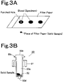
- the solid sample refers to a sample in which a liquid (or a solidified liquid) as a specimen is held by a solid medium, such as a piece of filter paper shown in FIG. 3A which is obtained by cutting a specimen portion (or a portion containing at least a specimen) of filter paper impregnated with blood (specimen) to a predetermined size (e.g. , 3 mm in diameter) .
- a solid sample is placed in the separation device 50, and the separation device 50 is set in the preprocessing container setting part 12 so that preprocessing such as extraction processing for extracting a specimen from the solid sample is automatically performed.
- an analyst When setting the separation device 50 containing a solid sample in the preprocessing container setting part 12, an analyst inputs information about a specimen contained in the solid sample and the position of this separation device 50 set in the preprocessing container setting part 12 to the apparatus.
- the apparatus identifies the position of the separation device 50 containing the specimen on the basis of the information input thereto and performs a preprocessing item designated by the analyst on the separation device 50. The details of preprocessing operations will be described later.
- the separation device 50 and the collection container 54 constituting the preprocessing container will be described with reference to FIG. 2A, FIG. 2B, FIG. 2C , and FIG. 2D .
- the separation device 50 is a cylindrical container having an internal space 50a in which a specimen and a reagent are to be contained.
- a separating layer 52 is provided at the bottom of the internal space 50a.
- the separating layer 52 is a separating agent or a separating membrane having the function of selectively separating a specific component in a specimen by allowing the specimen to pass therethrough to allow the specific component to physically or chemically react therewith.
- Examples of the separating agent used to form the separating layer 52 include an ion-exchange resin, silica gel, cellulose, and activated carbon.
- separating membrane examples include a PTFE (polytetrafluoroethylene) membrane, a nylon membrane, a polypropylene membrane, a PVDF (polyvinylidene fluoride) membrane, an acrylic copolymer membrane, a mixed cellulose membrane, a nitrocellulose membrane, a polyethersulfone membrane, an ion-exchange membrane, and a glass fiber membrane.
- PTFE polytetrafluoroethylene
- nylon membrane a polypropylene membrane
- PVDF polyvinylidene fluoride
- acrylic copolymer membrane an acrylic copolymer membrane
- mixed cellulose membrane a mixed cellulose membrane
- nitrocellulose membrane a nitrocellulose membrane
- polyethersulfone membrane an ion-exchange membrane
- ion-exchange membrane examples include a glass fiber membrane.
- a deproteinizing filter for removing protein in a specimen by filtration
- a PTFE membrane, an acrylic copolymer membrane, or the like can be used as a deproteinizing filter (separating membrane) for removing protein in a specimen by filtration
- a prefilter 52b may be provided above the deproteinizing filter 52a.
- a nylon membrane, a polypropylene membrane, a glass fiber membrane, or the like can be used as a prefilter 52b.
- the prefilter 52b is provided to remove insoluble matter and foreign matter having a relatively large particle diameter from a specimen, which makes it possible to prevent the deproteinizing filter 52a from being clogged with insoluble matter and foreign matter having a relatively large particle diameter.
- the separation device 50 has an opening 50b provided in its upper surface to inject a specimen or a reagent and an extract outlet 50d provided in its lower surface to discharge a liquid that has passed through the separating agent 52. Further, the separation device 50 has a flange 50c provided on its upper outer circumferential surface, and the flange 50c circumferentially protrudes so as to be engaged with the holding part 25 of the carrying arm 24 that will be described later.
- a skirt 51 is provided below the flange 50c so as to circumferentially protrude and then extend downward some distance to surround the outer circumferential surface of the separation device 50. As will be described later, the skirt 51 comes into close contact with the edge of a filtration port 30 of a processing part 28 when the separation device 50 is held in the filtration port 30 together with the collection container 54 so that an enclosed space is formed inside the skirt 51.
- the collection container 54 is a cylindrical container that holds the lower portion of the separation device 50 and collects an extract discharged through the extract outlet 50d of the separation device 50.
- the collection container 54 has, in its upper surface, an opening 50b through which the lower portion of the separation device 50 is to be inserted, and has an internal space 54a in which a portion of the separation device 50 located below the skirt 51 is to be held.
- the collection container 54 has a flange 54c provided on its upper outer circumferential surface, and the flange 54c circumferentially protrudes so as to be engaged with the holding part 25 of the carrying arm 24.
- the flange 54c has the same shape and outer diameter as the flange 50c of the separation device 50.
- the holding part 25 of the carrying arm 24 can hold the flange 50c of the separation device 50 and the flange 54c of the collection container 54 in the same manner.
- the preprocessing container setting part 12 the preprocessing container 50 and the collection container 54 are set in a state where the lower portion of the separation device 50 is held in the collection container 54 (i.e. , in a state shown in FIG. 2C ).
- the preprocessing apparatus 1 will be further described with reference to FIG. 1 .
- filtration ports 30, stirring ports 36a, temperature-control ports 38 for separation device 50, and temperature-control ports 40 for collection container 54 are provided in a preprocessing part.
- the filtration ports 30 are provided in two positions on the inner side of the preprocessing container setting part 12.
- the three stirring ports 36a are provided in a stirring part 36 provided adjacent to the preprocessing container setting part 12.
- the temperature-control ports 38 and 40 are provided along an arc.
- a dilution port 41 is provided adjacent to the temperature-control ports 40.
- the filtration ports 30 are connected to a negative-pressure applying mechanism 55 (see FIG. 4C and FIG. 5 ), and the negative-pressure applying mechanism 55 is configured to apply a negative pressure to the preprocessing container set in the filtration port 30.
- the filtration ports 30 and the negative-pressure applying mechanism 55 constitute the preprocessing part that performs the filtration of a specimen as preprocessing.
- the stirring part 36 also constitutes the preprocessing part.
- the stirring part 36 has a mechanism that periodically operates each of the stirring ports 36a in a horizontal plane individually to stir a specimen solution contained in the separation device 50 placed in each of the stirring ports 36a.
- the temperature-control ports 38 and 40 also constitute the preprocessing part.
- Each of the temperature-control ports 38 and 40 is provided in, for example, a heat-conductive block whose temperature is controlled by a heater and a Peltier element so that the separation device 50 or the collection container 54 held in the temperature-control port 38 or 40 is adjusted to a certain temperature.
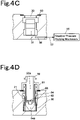
- the filtration port 30 will be described with reference to FIG. 4A, FIG. 4B , FIG. 4C, and FIG.4D .
- the filtration port 30 includes a recess in which the preprocessing container is to be held. As shown in FIG. 4D , the collection container 54 is first held in the filtration port 30, and then the lower portion of the separation device 50 is held in the internal space 54a of the collection container 54.
- a collection container holding member 31 is provided in the filtration port 30, a collection container holding member 31 is provided.
- the collection container holding member 31 evenly presses the collection container 54 from two opposite directions so as to sandwich the collection container 54 to center the collection container 54 (see FIG. 4B and FIG. 4D ) .
- the collection container holding member 31 is a U-shaped metal member that is upwardly open, and its two arms extending upwardly constitute two plate springs configured to be elastically displaced in the inner diameter direction of the filtration port 30.
- Each of the two plate springs of the collection container holding member 31 has a curved or bent shape that is inwardly curved or bent so that the distance between the two plate springs in a portion between the upper end and the lower end of the collection container holding member 31 is the smallest.
- the distance between the two plate springs at the upper end and lower end of the collection container holding member 31 is larger than the outer diameter of the collection container 54, and the smallest distance between the two plate springs is smaller than the outer diameter of the collection container 54. Since the collection container holding member 31 has such a shape, when the collection container 54 is inserted into the filtration port 30, the two plate springs of the collection container holding member 31 are opened as the collection container 54 comes down, and the collection container 54 is kept in the center of the filtration port 30 because of the elastic force of the plate springs. The collection container holding member 31 is fixed in the filtration port 30 so as not to be lifted up together with the collection container 54 when the collection container 54 is taken out of the filtration port 30.
- a ring-shaped sealing member 60 having elasticity is provided at the edge of the upper opening of the filtration port 30.
- the sealing member 60 is fitted into a recess provided around the edge of the upper opening of the filtration port 30.
- the sealing member 60 is made of an elastic material such as silicone rubber or EPDM (ethylene-propylene-diene rubber).
- the bottom surface of the filtration port 30 communicates with a flow path 56 for decompression (see FIG. 4A and FIG. 4C ) .
- the flow path 56 is connected to a flow path 57 of the negative-pressure applying mechanism 55.
- the negative-pressure applying mechanism 55 is designed to apply a negative pressure to the filtration port 30 with the use of a vacuum pump.
- a pressure difference is caused between the internal space 50a of the separation device 50 and the internal space 54a of the collection container 54 with the separating agent 52 being interposed therebetween so that only components, which can pass through the separating agent 52, of a sample solution contained in the internal space 50a of the separation device 50 are extracted and collected in the internal space 54a of the collection container 54 due to the pressure difference.
- FIG. 5 An example of the negative-pressure applying mechanism 55 is shown in FIG. 5 .
- the two filtration ports 30 are connected to a common vacuum tank 66.
- Each of the flow paths 57 that connects each of the filtration ports 30 to the vacuum tank 66 includes a pressure sensor 62 and a three-way valve 64.
- the pressure sensor 62 senses the pressure of the filtration port 30.
- the three-way valve 64 can select any one of a state where the filtration port 30 is connected to the vacuum tank 62, a state where the filtration port 30-side end of the flow path 57 is open to the atmosphere (i.e., a state shown in FIG. 5 ), and a state where the filtration port 30-side end of the flow path 57 is sealed.
- the vacuum tank 66 is connected to a pressure sensor 68, and is connected also to a vacuum pump 58 through a three-way valve 70. Therefore, the vacuum tank 66 can be connected to the vacuum pump 58, if necessary, to adjust the pressure in the vacuum tank 66.
- the filtration port 30 When extraction processing is performed on a specimen in any one of the filtration ports 30, the filtration port 30 is connected to the vacuum tank 66 to adjust a value sensed by the pressure sensor 62 that senses the pressure in the filtration port 30 to a predetermined value, and then the filtration port 30-side end of the flow path 57 is sealed. As a result, a sealed system is created in the filtration port 30 so that the inside of the filtration port 30 is kept decompressed to perform extraction processing on a specimen.
- FIG. 6A and FIG. 6B show one of the stirring ports 36a of the stirring part 36.
- the stirring port 36a of the stirring part 36 is a container that holds the separation device 50.
- the stirring port 36a is driven by a stirring mechanism provided below the stirring port 36a.
- a rotor 76 is provided below the stirring port 36a, and a driving shaft 74 is vertically attached to the upper surface of the rotor 76 in a position displaced from the center of the rotor 76.
- the upper end of the driving shaft 74 is inserted into a supporting hole 72 provided in the lower surface of the stirring port 36a.
- the rotor 76 is supported by a rotating shaft 78 that is rotated by a motor 80. Therefore, the rotor 76 is rotated by driving the motor 80 so that the driving shaft 74 is turned in a horizontal plane.
- a supporting frame 82 is attached to the motor 80.
- the supporting frame 82 has a side wall that extends vertically upward from the motor 80 side, and one end of an elastic member 83, such as a coil spring, is attached to the upper end of the side wall.
- the other end of the elastic member 83 is attached to the outer surface of the upper portion of the stirring port 36a to elastically hold the upper portion of the stirring port 36a.
- the elastic member 83 is provided in each of two or more positions (e.g., four positions) so that the elastic members 83 are evenly spaced around the stirring port 36a.
- the preprocessing apparatus 1 includes a sample transfer device 42 at the side edge of its housing.
- the sample transfer device 42 is provided to transfer an extracted sample collected in the collection container 54 to a sample injector (e.g., an automatic sampler) provided adjacent to the preprocessing apparatus 1.
- the sample transfer device 42 includes a moving part 44 that is moved by a driving mechanism having a rack and pinion mechanism in one direction (i.e., in a direction indicated by arrows in FIG. 1 ) in a horizontal plane.
- a transfer port 43 for setting the collection container 54 containing an extracted sample is provided in the upper surface of the moving part 44 .
- the transfer port 43 While sample transfer to the sample injector is not performed, the transfer port 43 is placed in a position along the track of the holding part 25 of the carrying arm 24 (i.e., in a position indicated by a solid line in FIG. 1 ). In a state where the transfer port 43 is placed in such a position, setting of the collection container 54 in the transfer port 43 or collection of the collection container 54 from the transfer port 43 is performed by the carrying arm 24.
- the collection container 54 containing an extracted specimen is set in the transfer port 43, and then the moving part 44 is moved toward the outside of the preprocessing apparatus 1, and the transfer port 43 is placed in a position closer to the sample injector adjacent to the preprocessing apparatus 1 (i.e. , in a position indicated by a dashed line in FIG. 1 ).
- a sampling nozzle provided in the sample injector sucks the specimen contained in the collection container 54.
- the moving part 44 is returned to its original position (i.e., a position indicated by a solid line in FIG. 1 ), and the collection container 54 is collected by the carrying arm 24.
- the used collection container 54 is carried to a disposal port 34 and disposed of by the carrying arm 24.
- the preprocessing apparatus 1 includes the disposal port 34 for disposing of the used separation device 50 and the used collection container 54.
- the disposal port 34 is provided in a position that is close to the dispensing port 32 and along the track of the holding part 25 of the carrying arm 24.
- the preprocessing apparatus 1 includes a washing port 45 for washing the sampling nozzle 20a.
- the washing port 45 is provided in a position along the track of the sampling nozzle 20a.
- a washing port for washing the probe 27 is provided in a position along the track of the probe 27.
- the term "port" refers to any one of the filtration port 30, the dispensing port 32, the stirring port 36a, the temperature-control ports 38 and 40, and the transfer port 43 in which the separation device 50 or the collection container 54 is to be set.
- the operations of the specimen setting part 2, the reagent setting part 8, the preprocessing container setting part 12, the sampling arm 20, the carrying arm 24, the reagent arm 26, the stirring part 36, the sample transfer device 42, and the negative-pressure applying mechanism 55 provided in the preprocessing apparatus 1 are controlled by a controller 84.
- the controller 84 is implemented by a computer provided in the preprocessing apparatus 1 and software executed by the computer.
- the controller 84 is connected to an arithmetic processing unit 86 implemented by, for example, a personal computer (PC) or a dedicated computer, and an analyst controls the preprocessing apparatus 1 through the arithmetic processing unit 86.
- PC personal computer
- the arithmetic processing unit 86 is electrically connected to a liquid chromatographic system (hereinafter referred to as "LC system") 200 (see FIG. 11 and FIG. 12 ) that is provided adjacent to the preprocessing apparatus 1 to analyze a sample that has been subjected to preprocessing in the preprocessing apparatus 1.
- LC system liquid chromatographic system
- a sample injector 202 provided in the LC system 200 is configured to operate in conjunction with the preprocessing apparatus 1.
- FIG. 7 shows only the sample injector 202 in the LC system 200.
- the controller 84 includes a preprocessing operation part 84a, a specimen recognition part 84b, a preprocessing container identification part 84c, and a solid sample setting information holding part 84d.
- Each of the preprocessing operation unit 84a, the specimen recognition part 84b, and the preprocessing container identification part 84c is a function achieved by execution of software by an arithmetic element such as a CPU constituting the controller 84.
- the solid sample setting information holding part 84d is a function achieved by the storage area of a storage device provided in a computer constituting the controller 84.
- the preprocessing apparatus 1 processes two kinds of specimens, one of which is a liquid specimen contained in the specimen container set in the specimen setting part 2 and the other of which is a specimen contained in a solid sample contained the separation device 50 set in the preprocessing container setting part 12.
- Information about a specimen to be analyzed is previously registered on the apparatus by an analyst.
- the controller 84 identifies a position where a specimen to be subjected to preprocessing next is set and a preprocessing item to be performed on the specimen on the basis of the registered information, and performs operations necessary for performing the preprocessing item.
- the preprocessing operation part 84a is configured to confirm a processing item to be performed next on each specimen, check the availability of a port for performing the processing item, carry the separation device 50 containing the specimen or the collection container 54 to the port when the port is available, and perform the processing item. On the other hand, when there is no available port for performing the processing item, the target separation device 50 or collection container 54 is carried to the port as soon as the port becomes available.
- the specimen recognition part 84b is configured to check whether a specimen to be analyzed is a liquid specimen or a specimen contained in a solid sample on the basis of previously-registered information.
- preprocessing operations for liquid specimen are performed.
- preprocessing operations for solid sample are performed. Each of the preprocessing operations will be described later.
- the preprocessing container identification part 84c is configured to, when the specimen recognition part 84b recognizes that a specimen to be analyzed is a specimen contained in a solid sample, identify the position of the preprocessing container (separation device 50) containing the solid sample on the basis of information about the specimen previously registered by an analyst. Information about a position where a solid sample is set is registered by an analyst and stored in the solid sample setting information holding part 84d when the separation device 50 containing the solid sample is set in the preprocessing container setting part 12.
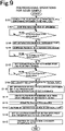
- FIG. 8 , FIG. 9 , and FIG. 10 An example of preprocessing operations performed on one sample according to this embodiment will be described with reference to FIG. 1 and flow charts shown in FIG. 8 , FIG. 9 , and FIG. 10 .
- the flow charts shown in FIGs. 8 to 10 show only the flow of preprocessing performed on one specimen, and the operations of the preprocessing are performed in parallel with but independently of the operations of preprocessing performed on another specimen.
- “To perform preprocessing in parallel with but independently of” means that while filtration processing or stirring processing is performed on a certain specimen in the filtration port 30 or the stirring port 36a, the separation device 50 or collection container 54 containing another specimen is carried to another port by the carrying arm 24 to independently perform processing on the another specimen.
- Step S1 the state of a specimen to be analyzed is checked, that is, it is checked whether a specimen to be analyzed is a liquid specimen or a specimen contained in a solid sample on the basis of information previously registered by an analyst (Step S1).
- Step S2 the specimen to be analyzed is a specimen contained in a solid sample
- Step S3 preprocessing operations for solid sample are performed
- Step S4 the specimen to be analyzed is not a specimen contained in a solid sample, that is, when the specimen to be analyzed is a liquid specimen contained in the specimen container (Step S2)
- preprocessing operations for liquid specimen are performed (Step S4).
- preprocessing operations performed on the specimen is preprocessing operations for newborn mass screening. An example of such preprocessing operations will be described with reference to FIG. 9 .
- Step S101 a position where the separation device 50 containing a solid sample containing a specimen to be analyzed is set is identified (Step S101), and an analysis item designated for the specimen is confirmed (Step S102).
- the separation device 50 containing a solid sample is taken out of the preprocessing container setting part 12 and set in the dispensing port 32 by the carrying arm 24 (Step S103 and Step S104).
- the separation device 50 and the collection container 54 are set in the preprocessing container setting part 12 in a state where they are stacked (i.e. , in a state shown in FIG. 2 ).
- the carrying arm 24 holds only the separation device 50 stacked on the collection container 54 with the use of the holding part 25 and carries the separation device 50 to the dispensing part 32.
- the reagent dispensing nozzle 26a takes a reagent for extracting the specimen from the solid sample from the reagent container 10 and dispenses the reagent into the separation device 50 set in the dispensing port 32 (Step S105) .
- a reagent dispensing port for dispensing a reagent may be provided in a position different from the position of the dispensing port 32 so that the separation device 50 is set in the reagent dispensing port by the carrying arm 24 to perform dispensing of a reagent in the position of the reagent dispensing port.
- An example of the reagent for specimen extraction is one obtained by dissolving stable isotopes (IS) of amino acids and acylcarnitines-32.
- Step S106 the availability of the stirring port 36a is checked.
- the separation device 50 set in the dispensing port 32 is carried and set in the available stirring port 36a by the carrying arm 24, and stirring is performed to extract the specimen from the solid sample (Step S107).
- the stirring processing is preferably performed under a temperature condition of about 45°C for about several tens of minutes. Therefore, the separation device 50, to which the reagent for specimen extraction has been added, is preferably carried to the temperature-control port 38 before the separation device 50 is carried to the stirring port 36a, that is, the separation device 50 is preferably carried to the stirring port 36a to perform stirring after the temperature of the separation device 50 is adjusted to about 45°C. Further, in order to stabilize the temperature of the separation device 50, the separation device 50, to which the reagent for specimen extraction has been added, may be alternately set in the temperature-control port 38 and the stirring port 36a to alternate temperature control and stirring.
- the processing from addition of a reagent to stirring is extraction processing for extracting the specimen from the solid sample.
- the availability of the filtration port 30 is checked (Step S108) .
- the collection container 54 is set in the filtration port 30 by the carrying arm 24 (Step S109).
- the collection container 54 set in the filtration port 30 is one paired with the separation device 50 that is being stirred in the stirring port 36a, that is, one that has been set in the preprocessing container setting part 12 with the separation device 50, which is being stirred, being stacked thereon.
- the carrying arm 24 may carry the separation device 50 or the collection container 54 for another sample.
- the carrying arm 24 carries the separation device 50 to the filtration port 30 and sets the separation device 50 on the collection container 54 so that the lower portion of the separation device 50 is held in the collection container 54 set in the filtration port 30 (a state shown in FIG. 4 , Step S110).
- the separation device 50 is pressed downward (i.e., toward the filtration port 30) so that the lower end of the skirt 51 of the separation device 50 comes down to a level slightly lower (e.g., about 0.1 mm) than the level of the upper surface of the sealing member 60 provided around the filtration port 30.
- the lower end of the skirt 51 of the separation device 50 compresses the sealing member 60, which improves air tightness between the lower end of the skirt 51 and the sealing member 60.
- the carrying arm 24 keeps pressing the separation device 50 downward until a negative pressure is caused in the filtration port 30 after the start of filtration processing that will be described below.
- Filtration processing is started in a state where the separation device 50 is set on the collection container 54 set in the filtration port 30 and the filtration port 30 is hermetically sealed.
- the filtration port 30 is decompressed by the negative-pressure applying mechanism 55 so that a negative pressure is caused in the filtration port 30 holding the separation device 50 and the collection container 54.
- the filtration port 30 is kept at negative pressure for a certain period of time so that the solution contained in the separation device 50 is filtered and an extracted specimen is collected in the collection container 54 (Step S111).
- the carrying arm 24 stops pressing the separation device 50 downward and holding the separation device 50. After stopping of holding the separation device 50, the carrying arm 24 can carry another separation device 50 or collection container 54.
- the stopping of downward pressing of the separation device 50 and holding of the separation device 50, which are performed by the carrying arm 24, is not necessarily performed on the basis of the detection signal of the pressure sensor 62, and may be performed after predetermined time elapses from the start of the filtration processing.
- Step S112 After the filtration processing of the specimen is finished (Step S112), the three-way valve 64 (see FIG. 5 ) is switched to return the pressure in the filtration port 30 to atmospheric pressure, and the used separation device 50 is taken out of the filtration port 30 and disposed of in the disposal port 34 by the holding part 25 of the carrying arm 24 (Step S113) . Then, the collection container 54 containing the filtered specimen is allowed to stand to allow a derivatization reaction of succinylacetone with hydrazine under acidic conditions to proceed. The time required for this processing is about several tens of minutes to 2 hours. This processing can be performed in the temperature-control port 40.
- the availability of the transfer port 43 is checked.
- the collection container 54 is set in the transfer port 43 by the carrying arm 24.
- the moving part 44 is moved to a position (i.e., a position indicated by a dashed line in FIG. 1 ) closer to the sample injector 202 provided in the LC system 200 (see FIG. 11 and FIG. 12 ) provided adjacent to the preprocessing apparatus 1 so that the collection container 54 is transferred to the sample suction device 90 (Step S114).
- the specimen contained in the collection container 54 transferred by the transfer device 42 is sucked by a sampling nozzle.
- the moving part 44 stops in the position closer to the LC system 200 until the suction of the specimen performed in the sample injector 202 is finished, and then the moving part 44 returns to its original position (i.e., a position indicated by a solid line in FIG. 1 ) when receiving a signal indicating that the suction of the specimen has finished from the LC system 200.
- the used collection container 54 is collected from the transfer port 43 and disposed of in the disposal port 34 by the carrying arm 24 (Step S115).
- Step S201 When a specimen to be analyzed is a liquid specimen, an analysis item previously designated by an analyst for the specimen is first confirmed (Step S201), and a preprocessing item necessary for performing the analysis item is determined. The availability of the dispensing port 32 is checked. When the dispensing port 32 is available, the carrying arm 24 takes the unused separation device 50 for containing the specimen out of the preprocessing container setting part 12 and sets the separation device 50 in the dispensing port 32 (Steps S202 and S203) . As has been described above, the separation device 50 and the collection container 54 are set in the preprocessing container setting part 12 in a state where they are stacked (i.e., in a state shown in FIG. 2C ), but also in this case, the carrying arm 24 holds only the separation device 50 stacked on the collection container 54 with the use of the holding part 25 and carries the separation device 50 to the dispensing part 32.
- the sampling nozzle 20a dispenses the specimen into the separation device 50 (Step S204). After dispensing the specimen into the separation device 50, the sampling nozzle 20a is washed in the washing port 45 and prepared for dispensing of a next specimen.
- the reagent dispensing nozzle 26a takes a reagent appropriate to preprocessing to be performed on the specimen dispensed into the separation device 50 from the reagent container 10 and dispenses the reagent into the separation device 50 set in the dispensing port 32 (Step S205) . It is to be noted that the dispensing of the reagent into the separation device 50 may be performed before the dispensing of the sample.
- Step S206 the availability of the stirring port 36a is checked.
- the stirring port 36a is available, the separation device 50 set in the dispensing port 32 is carried and set in the available stirring port 36a by the carrying arm 24 to perform stirring (Step S207) .
- This stirring processing is performed for a predetermined certain period of time to mix the specimen and the reagent contained in the separation device 50.
- the availability of the filtration port 30 is checked (Step S208) .
- the collection container 54 is set in the filtration port 30 by the carrying arm 24 (Step S209).
- the carrying arm 24 carries the separation device 50 to the filtration port 30 and sets the separation device 50 on the collection container 54 (a state shown in FIG. 4D ), and further presses the separation device 50 downward (i.e., toward the filtration port 30) to improve air tightness between the lower end of the skirt 51 and the sealing member 60 (Step S210) .
- the carrying arm 24 keeps pressing the separation device 50 downward until a negative pressure is caused in the filtration port 30 after the start of filtration processing that will be described below.
- the filtration port 30 is decompressed by the negative-pressure applying mechanism 55 to perform filtration processing.
- the filtration port 30 is kept at negative pressure for a certain period of time so that the solution contained in the separation device 50 is filtered and an extracted specimen is collected in the collection container 54 (Step S211).
- the carrying arm 24 stops pressing the separation device 50 downward and holding the separation device 50. After stopping of holding the separation device 50, the carrying arm 24 can carry another separation device 50 or collection container 54.
- the stopping of downward pressing of the separation device 50 and holding of the separation device 50, which are performed by the carrying arm 24, is not necessarily performed on the basis of the detection signal of the pressure sensor 62, and may be performed after predetermined time elapses from the start of the filtration processing.
- temperature treatment is sometimes incorporated in which the sample contained in the separation device 50 is kept at a given temperature for a certain period of time after the sample contained in the separation device 50 is stirred.
- the availability of the temperature control port 40 is checked.
- the separation device 50 is set in the available temperature control port 38.
- the separation device 50 is taken out of the temperature control port 38 and then set on the collection container 54 set in the filtration port 30.
- Step S212 After the completion of the filtration processing of the specimen (Step S212), the three-way valve 64 (see FIG. 5 ) is switched to return the pressure in the filtration port 30 to atmospheric pressure, and the used separation device 50 is taken out of the filtration port 30 and disposed of in the disposal port 34 by the holding part 25 of the carrying arm 24 (Step S213) .
- the carrying arm 24 sets the collection container 54 in the transfer port 43 to transfer the specimen to the sample injector 202 (Step S214), and collects the used collection container 54 from the transfer port 43 to dispose of the used collection container 54 in the disposal port 34 (Step S215).
- temperature treatment is sometimes performed in which the extracted sample collected in the collection container 54 is kept at a certain temperature for a certain period of time.
- the availability of the temperature control port 40 is checked.
- the collection container 54 is set in the available temperature control port 40. Then, after a lapse of a certain period of time, the collection container 54 is carried from the temperature control port 40 to the transfer port 43 to perform sample transfer.
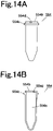
- a separation device 550 and a collection container 554 that can be used instead of the separation device 50 and the collection container 54 shown in FIG. 2A to FIG. 2D will be described with reference to FIG. 13A, FIG. 13B , FIG. 14A, and FIG. 14B .
- differences between the separation device 50 and the separation device 550 and differences between the collection container 54 and the collection container 554 will be described.
- the inner diameter and outer diameter of a portion located below the base of a skirt 551 are smaller than those of a portion located above the base of the skirt 551.
- the lower portion of the device is to be held in a space 554a of the collection container 554. This allows a portion of the separation device 550 where a flange 550c is provided to have the same outer diameter as a portion of the collection container 554 where a flange 554c is provided.
- the flange 550c of the separation device 550 and the flange 554c of the collection container 554 can have completely the same shape and size, and therefore the holding part 25 of the carrying arm 24 can hold the separation device 550 and the collection container 554 in the same manner
- a protrusion 550e is provided between the flange 550c and the base of the skirt 551 on the outer circumferential surface of the separation device 550 so as to circumferentially protrude in the form of a flange like the flange 550c.
- the protrusion 550e is provided in a position such that the upper edge of the inner wall surface of the stirring port 36a is located when the separation device 550 is set in the stirring port 36a.
- the protrusion 550e has the same outer diameter as the skirt 551, which allows, when the stirring processing is performed, the protrusion 550e to abut against the upper edge of the inner wall surface of the stirring port 36a to prevent the vibration of the separation device 550 in the stirring port 36a.
- notches 554d are provided in two or more (e.g., three) positions at the edge of an upper opening 554b.
- the notches 554d form openings for the ventilation of air between the inner wall surface of the base of the skirt 551 and the upper edge of the collection container 554 when the separation device 550 and the collection container 554 are integrated with each other so that the upper portion of the collection container 554 enters the inside of the skirt 551 of the separation device 550.
- the filtration processing in the filtration port 30 is performed by sucking air in the filtration port 30 to cause a negative pressure in the collection container 554 integrated with the separation device 550 and set in the filtration port 30. At this time, air in the collection container 554 passes through the openings formed by the notches 554d so that the collection container 554 is efficiently decompressed.
- An LC system 200 is provided adjacent to the preprocessing apparatus 1 described with reference to the above embodiment, and a mass spectrometer (MS) 300 is further provided adjacent to the LC system 200.
- the operations of the preprocessing apparatus 1, the LC system 200, and the MS 300 are managed by a common system management unit 400.
- the system management unit 400 is a dedicated computer or a general-purpose personal computer that includes software for controlling or managing the preprocessing apparatus 1, the LC system 200, and the MS 300, and also has the function of the arithmetic processing unit 100 shown in FIG. 7 .
- the LC system 200 includes the sample injector 202 that takes a specimen that has been subjected to preprocessing in the preprocessing apparatus 1 and injects the specimen into the analytical flow path of a liquid chromatograph.
- the preprocessing apparatus 1 includes the transfer device 42 that transfers the collection container 54 (or 554) containing a specimen that has been subjected to preprocessing to the LC system 200, and the sample injector 202 is configured to take the specimen from the collection container 54 (or 554) transferred to the LC system 200 by the transfer device 42.
- the transfer device 42 that transfers the collection container 54 (or 554) containing a specimen that has been subjected to preprocessing to the LC system 200
- the sample injector 202 is configured to take the specimen from the collection container 54 (or 554) transferred to the LC system 200 by the transfer device 42.
- the transfer port 43 of the transfer device 42 When the collection container 54 (or 554) containing a specimen that has been subjected to preprocessing in the preprocessing apparatus 1 is set in the transfer port 43 of the transfer device 42, and the moving part 44 is moved toward the LC system 200 so that the collection container 54 (or 554) is placed in a predetermined position in the sample injector 202, a signal indicating this is sent to the sample injector 202 through the system management unit 400, and the sample injector 202 starts taking the specimen from the collection container 54 (or 554).
- the transfer device 42 keeps the collection container 54 (or 554) in a predetermined position in the sample injector 202 until the sample injector 202 finishes taking the specimen as a sample.
- a signal indicating this is sent to the preprocessing apparatus 1 through the system management unit 400 so that the transfer device 42 moves the moving part 44 toward the preprocessing apparatus 1 to return the collection container 54 (or 554) to a predetermined position in the preprocessing apparatus 1.
- the collection container 54 (or 554) returned to the preprocessing apparatus 1 is carried to the disposal port 34 and disposed of by the carrying arm 24 .
- the LC system 200 according to this embodiment will be described with reference to FIG. 12 .
- the LC system 200 includes, in addition to the sample injector 202, a liquid sending device 204, a column oven 206, and a detector 208.
- the liquid sending device 204 is a device that sends, for example, two kinds of solvents with the use of liquid sending pumps to a mixer and sends a solution obtained by mixing them with the mixer as a mobile phase.
- the column oven 206 has an analytical column 207 that separates a sample (a specimen that has been subjected to preprocessing) into individual components.
- the detector 208 is a detector such as an ultraviolet absorption detector that detects sample components separated by the analytical column 207.
- the liquid sending device 204 is located at the upstream end of an upstream analytical flow path 218 to send a mobile phase through the upstream analytical flow path 218.
- the analytical column 207 and the detector 208 are provided on a downstream analytical flow path 220. Both the upstream analytical flow path 218 and the downstream analytical flow path 220 are connected to ports of a two-position valve 210 provided in the sample injector 202, and are therefore connected to each other through the two-position valve 210.
- the two-position valve 210 of the sample injector 202 have 6 ports.
- the ports of the two-position valve 210 are connected not only to the upstream analytical flow path 218 and the downstream analytical flow path 220 but also to a sample introduction flow path 212, a drainage flow path 214, and one end and the other end of a sample loop 216. They are configured so that one of the following states (1) and (2) can be selected by switching the two-position valve 210: (1) a state where the sample introduction flow path 212, the sample loop 216, and the drainage flow path 214 are connected in series so that the downstream end of the upstream analytical flow path 218 is directly connected to the downstream analytical flow path 220 (i.e., a state shown in FIG. 12 ) and ( 2 ) a state where the upstream analytical flow path 218, the sample loop 216, and the downstream analytical flow path 220 are connected in series.
- the sample introduction flow path 212 communicates with an injection port 213.
- the sample injector 202 has a needle 222 that can inject and discharge a liquid from its tip and a syringe pump 226 connected to the needle 222 through a flow path.
- the needle 222 is configured to be horizontally and vertically moved by a driving mechanism not shown in the drawing, and therefore can take a sample from the collection container 54 (or 554) transferred to the LC system 200 by the transfer device 42 and inject the sample through the injection port 213.
- the syringe pump 226 is configured to be connected also to a washing liquid container 228 that stores a washing liquid by switching a flow path switching valve 230.
- the inner surfaces of a sample loop 224, the needle 222, and the sample introduction flow path 212 can be washed by sending the washing liquid from the syringe pump 226 containing the washing liquid sucked thereinto in a state where the syringe pump228 is connected to the needle 222 and the needle 222 is connected to the injection port 213.
- the tip of the needle 22 is inserted into the collection container 54 (or 554), the syringe pump 226 sucks the sample, and the sample is held in the sample loop 224 provided between the needle 222 and the syringe pump 226.
- the sample held in the sample loop 224 is injected through the injection port 213.
- the two-position valve 210 is operated to select the state (1) where the sample introduction flow path 212, the sample loop 216, and the drainage flow path 214 are connected in series so that the sample injected through the injection port 213 is held in the sample loop 216.
- the two-position valve 210 is switched to select the state (2) where the upstream analytical flow path 218, the sample loop 216, and the downstream analytical flow path 220 are connected in series so that the sample held in the sample loop 216 is introduced into the analytical column 207 by a mobile phase sent by the liquid sending device 204 and separated into individual components by the analytical column 207.
- the individual components separated by the analytical column 207 are detected by the detector 208 and then further introduced into the MS 300.
- Signals obtained by the detector 208 and the MS 300 are input into the system management unit 400 (see FIG. 11 ) and arithmetic processing such as quantitative determination and composition analysis of individual components separated by the analytical column 207 is performed by software installed in the system management unit 400 and hardware, such as a CPU, that executes the software.
Landscapes
- Health & Medical Sciences (AREA)
- Life Sciences & Earth Sciences (AREA)
- Chemical & Material Sciences (AREA)
- Physics & Mathematics (AREA)
- General Health & Medical Sciences (AREA)
- Analytical Chemistry (AREA)
- Biochemistry (AREA)
- General Physics & Mathematics (AREA)
- Immunology (AREA)
- Pathology (AREA)
- Engineering & Computer Science (AREA)
- Biomedical Technology (AREA)
- Hematology (AREA)
- Urology & Nephrology (AREA)
- Ecology (AREA)
- Biophysics (AREA)
- Molecular Biology (AREA)
- Food Science & Technology (AREA)
- Medicinal Chemistry (AREA)
- Chemical Kinetics & Catalysis (AREA)
- Clinical Laboratory Science (AREA)
- Sampling And Sample Adjustment (AREA)
- Automatic Analysis And Handling Materials Therefor (AREA)
- Investigating Or Analysing Biological Materials (AREA)
Claims (5)
- Un appareil de prétraitement (1) comprenant :une partie de mise en place de récipient de prétraitement (12) dans laquelle un récipient de prétraitement (50, 54) contenant un échantillon solide comprenant un spécimen à analyser et un milieu solide contenant le spécimen doit être mis en place ;un mécanisme de transport (24) qui transporte le récipient de prétraitement (50, 54) placé dans la partie de mise en place de récipient de prétraitement (12) ; etune partie de prétraitement (30, 38, 40, 55) qui présente un orifice (30) pour mettre en place le récipient de prétraitement (50, 54) transporté par le mécanisme de transport (24), et qui est configurée pour effectuer un prétraitement incluant un traitement d'extraction pour extraire le spécimen de l'échantillon solide contenu dans le récipient de prétraitement (50, 54) placé dans l'orifice (30), etsachant que la partie de mise en place de récipient de prétraitement (12) est configurée pour permettre à un récipient de prétraitement (50, 54) vide, ne contenant aucun spécimen, d'être également mis en place dans celle-ci,l'appareil de prétraitement (1) comprenant en outre :une partie de mise en place de spécimen (2) dans laquelle un récipient de spécimen (6) contenant un spécimen liquide doit être mis en place ;une partie de distribution de spécimen (20) qui prend le spécimen du récipient de spécimen (6) placé dans la partie de mise en place de spécimen (2) et distribue le spécimen dans le récipient de prétraitement (50, 54) vide placé dans une position de distribution prédéterminée ; etun dispositif de commande (84) pour commander les opérations de l'appareil de prétraitement (1),caractérisé en ce quele dispositif de commande (84) comprend une partie de reconnaissance de spécimen (84b) configurée pour vérifier si un spécimen à analyser est un spécimen liquide ou un spécimen contenu dans l'échantillon solide sur la base d'informations enregistrées précédemment, et quele dispositif de commande (84) est configuré pour amener l'appareil de prétraitement (1) à effectuer des opérations de prétraitement pour un spécimen liquide lorsque la partie de reconnaissance de spécimen reconnaît qu'un spécimen à analyser est un spécimen liquide, et quele dispositif de commande (84) est configuré pour amener l'appareil de prétraitement (1) à effectuer des opérations de prétraitement pour un échantillon solide lorsque la partie de reconnaissance de spécimen reconnaît qu'un spécimen à analyser est un spécimen contenu dans un échantillon solide.
- L'appareil de prétraitement (1) d'après la revendication 1, sachant que le dispositif de commande (84) comprend une partie d'opération de prétraitement (84a) qui est configurée pour, lorsque la partie de reconnaissance de spécimen (84b) reconnaît qu'un spécimen à analyser est un spécimen liquide, permettre au mécanisme de transport (24) de transporter le récipient de prétraitement (50, 54) vide placé dans la partie de mise en place de récipient de prétraitement (12) vers la position de distribution, permettre à la partie de distribution de spécimen (20) de distribuer le spécimen à analyser dans le récipient de prétraitement (50, 54), puis permettre au mécanisme de transport (24) de transporter le récipient de prétraitement (50, 54) vers la partie de prétraitement (30, 38, 40, 55) pour effectuer un prétraitement prédéterminé, et qui est configuré pour, lorsque la partie de reconnaissance de spécimen (84b) reconnaît qu'un spécimen à analyser est un spécimen contenu dans l'échantillon solide, permettre au mécanisme de transport (24) de transporter le récipient de prétraitement (50, 54) contenant l'échantillon solide et placé dans la partie de mise en place de récipient de prétraitement (12), vers la partie de prétraitement (30, 38, 40, 55) pour effectuer un prétraitement prédéterminé incluant le traitement d'extraction.
- L'appareil de prétraitement (1) d'après la revendication 2, sachant quela partie de prétraitement (30, 38, 40, 55) présente une pluralité d'orifices d'extraction (30) pour effectuer le traitement d'extraction, et quela partie d'opération de prétraitement (84a) est configurée pour, lorsque la partie de reconnaissance de spécimen (84b) reconnaît qu'un spécimen à analyser est un spécimen contenu dans l'échantillon solide, rechercher l'orifice d'extraction (30) disponible et permettre au mécanisme de transport (24) de transporter le récipient de prétraitement (50, 54) cible vers l'orifice d'extraction (30) disponible pour effectuer le traitement d'extraction.
- L'appareil de prétraitement (1) d'après l'une quelconque des revendications précédentes, sachant quela partie de mise en place de conteneur de prétraitement (12) est configurée pour permettre à une pluralité de conteneurs de prétraitement (50, 54) d'y être placés,le dispositif de commande (84) de l'appareil de prétraitement (1) comprenant en outre :une partie de conservation d'informations de mise en place d'échantillon solide (84d) contenant des informations concernant une position où le récipient de prétraitement (50, 54) contenant l'échantillon solide est mis en place dans la partie de mise en place de récipient de prétraitement (12) ; etune partie d'identification de récipient de prétraitement (84c) configurée pour, lorsqu'un spécimen à analyser est un spécimen contenu dans l'échantillon solide, identifier le récipient de prétraitement (50, 54) contenant l'échantillon solide contenant le spécimen sur la base des informations contenues dans la partie de conservation d'informations de mise en place d'échantillon solide (84d).
- Un système d'analyse comprenant :l'appareil de prétraitement (1) d'après l'une quelconque des revendications précédentes comprenant un dispositif de transfert (42) qui présente un orifice de transfert (43) où le récipient de prétraitement (50, 54) contenant un spécimen qui a été soumis à un prétraitement dans la partie de prétraitement (30, 38, 40, 55) doit être placé par le mécanisme de transport (24), et qui est configuré pour déplacer l'orifice de transfert (43) pour transférer le récipient placé dans l'orifice de transfert (43) vers un extérieur de l'appareil de prétraitement (1) ; etun système de chromatographie en phase liquide (200) qui est prévu de manière adjacente à l'appareil de prétraitement (1) et qui présente un chemin d'écoulement analytique (218, 220) qui permet à une phase mobile de s'écouler à travers celui-ci, un injecteur d'échantillon (202) qui prend, en tant qu'échantillon, le spécimen contenu dans le récipient déplacé vers l'extérieur de l'appareil de prétraitement (1) par le dispositif de transfert (42) et injecte l'échantillon dans le chemin d'écoulement analytique (218, 220), une colonne analytique (207) prévue sur le chemin d'écoulement analytique (218, 220) pour séparer l'échantillon injecté par l'injecteur d'échantillon (202) en composants individuels, et un détecteur (208) qui détecte les composants de l'échantillon séparés par la colonne analytique (207).
Applications Claiming Priority (1)
| Application Number | Priority Date | Filing Date | Title |
|---|---|---|---|
| JP2017040356A JP6784196B2 (ja) | 2017-03-03 | 2017-03-03 | 前処理装置及びその前処理装置を備えた分析システム |
Publications (2)
| Publication Number | Publication Date |
|---|---|
| EP3370056A1 EP3370056A1 (fr) | 2018-09-05 |
| EP3370056B1 true EP3370056B1 (fr) | 2022-03-30 |
Family
ID=61526512
Family Applications (1)
| Application Number | Title | Priority Date | Filing Date |
|---|---|---|---|
| EP18000194.3A Active EP3370056B1 (fr) | 2017-03-03 | 2018-02-27 | Appareil de prétraitement et système d'analyse comprenant l'appareil de prétraitement |
Country Status (3)
| Country | Link |
|---|---|
| US (2) | US20180252682A1 (fr) |
| EP (1) | EP3370056B1 (fr) |
| JP (1) | JP6784196B2 (fr) |
Families Citing this family (8)
| Publication number | Priority date | Publication date | Assignee | Title |
|---|---|---|---|---|
| AU2013202805B2 (en) | 2013-03-14 | 2015-07-16 | Gen-Probe Incorporated | System and method for extending the capabilities of a diagnostic analyzer |
| JP7035951B2 (ja) | 2018-10-16 | 2022-03-15 | 株式会社島津製作所 | 前処理装置およびこれを備えた分析システム |
| JP7358769B2 (ja) * | 2019-04-19 | 2023-10-11 | 株式会社島津製作所 | 前処理装置 |
| CN112147345B (zh) * | 2019-06-28 | 2024-05-17 | 深圳迈瑞生物医疗电子股份有限公司 | 清除残留反应杯的方法、样本分析设备和存储介质 |
| CN115516308B (zh) | 2020-03-17 | 2025-08-19 | 沃特世科技公司 | 针驱动器、系统和方法 |
| CN115667908B (zh) * | 2020-03-17 | 2026-02-10 | 沃特世科技公司 | 样品管理器、系统和方法 |
| CN111721832B (zh) * | 2020-07-06 | 2022-12-30 | 广西壮族自治区亚热带作物研究所(广西亚热带农产品加工研究所) | 一种西番莲果肉物质检测装置及其检测方法 |
| GB202105909D0 (en) * | 2021-04-26 | 2021-06-09 | Cytiva Sweden Ab | Gb2105909.2 |
Family Cites Families (12)
| Publication number | Priority date | Publication date | Assignee | Title |
|---|---|---|---|---|
| US4859605A (en) * | 1986-12-16 | 1989-08-22 | Ciba-Geigy Corporation | Process for preparation of samples for analysis |
| JP5530609B2 (ja) | 2008-09-05 | 2014-06-25 | 株式会社日立ハイテクノロジーズ | 前処理装置及びそれを備えた質量分析装置 |
| WO2010087109A1 (fr) * | 2009-01-29 | 2010-08-05 | 株式会社 日立ハイテクノロジーズ | Dispositif de prétraitement d'échantillon biologique et spectromètre de masse équipé de celui-ci |
| JP5611951B2 (ja) * | 2009-08-10 | 2014-10-22 | 株式会社日立ハイテクノロジーズ | 試料処理システム |
| JP5242532B2 (ja) * | 2009-10-16 | 2013-07-24 | 株式会社日立ハイテクノロジーズ | 検査装置 |
| JP6154384B2 (ja) * | 2011-09-23 | 2017-06-28 | ウオーターズ・テクノロジーズ・コーポレイシヨン | 乾燥サンプルカード用固相抽出デバイス |
| JP2013096733A (ja) * | 2011-10-28 | 2013-05-20 | Hitachi High-Technologies Corp | 分析装置および分析方法 |
| CN106537138B (zh) * | 2014-07-28 | 2019-03-15 | 株式会社岛津制作所 | 预处理组件、使用该预处理组件进行试样的预处理的预处理装置及包括该预处理装置的分析系统 |
| CN106999955B (zh) * | 2014-07-29 | 2020-10-23 | 约阿希姆·格斯特尔 | 用于准备大量用于分析方法的试样的组件 |
| JP6264465B2 (ja) * | 2014-09-02 | 2018-01-24 | 株式会社島津製作所 | 前処理装置及びこれを備えた分析システム |
| JP6418017B2 (ja) | 2015-03-13 | 2018-11-07 | 株式会社島津製作所 | 前処理装置及びこれを備えた分析システム |
| WO2017006476A1 (fr) * | 2015-07-09 | 2017-01-12 | 株式会社島津製作所 | Dispositif de prétraitement, et système d'analyse le comportant |
-
2017
- 2017-03-03 JP JP2017040356A patent/JP6784196B2/ja active Active
-
2018
- 2018-02-27 EP EP18000194.3A patent/EP3370056B1/fr active Active
- 2018-02-27 US US15/905,954 patent/US20180252682A1/en not_active Abandoned
-
2020
- 2020-09-01 US US17/009,302 patent/US11385206B2/en active Active
Also Published As
| Publication number | Publication date |
|---|---|
| JP2018146333A (ja) | 2018-09-20 |
| US11385206B2 (en) | 2022-07-12 |
| US20200393424A1 (en) | 2020-12-17 |
| EP3370056A1 (fr) | 2018-09-05 |
| JP6784196B2 (ja) | 2020-11-11 |
| US20180252682A1 (en) | 2018-09-06 |
Similar Documents
| Publication | Publication Date | Title |
|---|---|---|
| EP3370056B1 (fr) | Appareil de prétraitement et système d'analyse comprenant l'appareil de prétraitement | |
| JP6658793B2 (ja) | 前処理キット、その前処理キットを用いて試料の前処理を行なう前処理装置及びその前処理装置を備えた分析システム | |
| EP2466289B1 (fr) | Système de traitement d échantillon | |
| EP3165916B1 (fr) | Appareil de prétraitement | |
| JPH11215978A (ja) | 核酸抽出装置 | |
| US11326990B2 (en) | Autonomous preprocessing device and analysis system provided with the autonomous preprocessing device | |
| EP3531104B1 (fr) | Procédé de prétraitement d'un échantillon maintenu dans un microcanal, appareil de prétraitement pour la mise en oeuvre du procédé de prétraitement et système d'analyse pourvu d'un appareil de prétraitement | |
| JP2024023491A (ja) | ウラシルおよびジヒドロウラシルの分析方法 | |
| JP6481761B2 (ja) | 前処理装置及びこれを備えた分析システム | |
| EP3438675B1 (fr) | Appareil de prétraitement et système d'analyse comprenant l'appareil de prétraitement | |
| CN110192093B (zh) | 预处理系统 | |
| JP2016205998A (ja) | 分注装置 |
Legal Events
| Date | Code | Title | Description |
|---|---|---|---|
| PUAI | Public reference made under article 153(3) epc to a published international application that has entered the european phase |
Free format text: ORIGINAL CODE: 0009012 |
|
| STAA | Information on the status of an ep patent application or granted ep patent |
Free format text: STATUS: THE APPLICATION HAS BEEN PUBLISHED |
|
| AK | Designated contracting states |
Kind code of ref document: A1 Designated state(s): AL AT BE BG CH CY CZ DE DK EE ES FI FR GB GR HR HU IE IS IT LI LT LU LV MC MK MT NL NO PL PT RO RS SE SI SK SM TR |
|
| AX | Request for extension of the european patent |
Extension state: BA ME |
|
| STAA | Information on the status of an ep patent application or granted ep patent |
Free format text: STATUS: REQUEST FOR EXAMINATION WAS MADE |
|
| 17P | Request for examination filed |
Effective date: 20190228 |
|
| RBV | Designated contracting states (corrected) |
Designated state(s): AL AT BE BG CH CY CZ DE DK EE ES FI FR GB GR HR HU IE IS IT LI LT LU LV MC MK MT NL NO PL PT RO RS SE SI SK SM TR |
|
| STAA | Information on the status of an ep patent application or granted ep patent |
Free format text: STATUS: EXAMINATION IS IN PROGRESS |
|
| 17Q | First examination report despatched |
Effective date: 20210210 |
|
| GRAP | Despatch of communication of intention to grant a patent |
Free format text: ORIGINAL CODE: EPIDOSNIGR1 |
|
| STAA | Information on the status of an ep patent application or granted ep patent |
Free format text: STATUS: GRANT OF PATENT IS INTENDED |
|
| RIC1 | Information provided on ipc code assigned before grant |
Ipc: G01N 30/00 20060101ALN20210903BHEP Ipc: B01L 3/00 20060101ALN20210903BHEP Ipc: G01N 35/10 20060101ALN20210903BHEP Ipc: G01N 35/00 20060101ALN20210903BHEP Ipc: G01N 30/06 20060101ALN20210903BHEP Ipc: G01N 1/28 20060101ALN20210903BHEP Ipc: G01N 35/04 20060101ALI20210903BHEP Ipc: G01N 1/40 20060101AFI20210903BHEP |
|
| INTG | Intention to grant announced |
Effective date: 20210924 |
|
| RIN1 | Information on inventor provided before grant (corrected) |
Inventor name: HANAFUSA, NOBUHIRO |
|
| GRAS | Grant fee paid |
Free format text: ORIGINAL CODE: EPIDOSNIGR3 |
|
| GRAA | (expected) grant |
Free format text: ORIGINAL CODE: 0009210 |
|
| STAA | Information on the status of an ep patent application or granted ep patent |
Free format text: STATUS: THE PATENT HAS BEEN GRANTED |
|
| AK | Designated contracting states |
Kind code of ref document: B1 Designated state(s): AL AT BE BG CH CY CZ DE DK EE ES FI FR GB GR HR HU IE IS IT LI LT LU LV MC MK MT NL NO PL PT RO RS SE SI SK SM TR |
|
| REG | Reference to a national code |
Ref country code: GB Ref legal event code: FG4D |
|
| REG | Reference to a national code |
Ref country code: CH Ref legal event code: EP |
|
| REG | Reference to a national code |
Ref country code: AT Ref legal event code: REF Ref document number: 1479630 Country of ref document: AT Kind code of ref document: T Effective date: 20220415 |
|
| REG | Reference to a national code |
Ref country code: DE Ref legal event code: R096 Ref document number: 602018032806 Country of ref document: DE |
|
| REG | Reference to a national code |
Ref country code: IE Ref legal event code: FG4D |
|
| REG | Reference to a national code |
Ref country code: LT Ref legal event code: MG9D |
|
| PG25 | Lapsed in a contracting state [announced via postgrant information from national office to epo] |
Ref country code: SE Free format text: LAPSE BECAUSE OF FAILURE TO SUBMIT A TRANSLATION OF THE DESCRIPTION OR TO PAY THE FEE WITHIN THE PRESCRIBED TIME-LIMIT Effective date: 20220330 Ref country code: RS Free format text: LAPSE BECAUSE OF FAILURE TO SUBMIT A TRANSLATION OF THE DESCRIPTION OR TO PAY THE FEE WITHIN THE PRESCRIBED TIME-LIMIT Effective date: 20220330 Ref country code: NO Free format text: LAPSE BECAUSE OF FAILURE TO SUBMIT A TRANSLATION OF THE DESCRIPTION OR TO PAY THE FEE WITHIN THE PRESCRIBED TIME-LIMIT Effective date: 20220630 Ref country code: LT Free format text: LAPSE BECAUSE OF FAILURE TO SUBMIT A TRANSLATION OF THE DESCRIPTION OR TO PAY THE FEE WITHIN THE PRESCRIBED TIME-LIMIT Effective date: 20220330 Ref country code: HR Free format text: LAPSE BECAUSE OF FAILURE TO SUBMIT A TRANSLATION OF THE DESCRIPTION OR TO PAY THE FEE WITHIN THE PRESCRIBED TIME-LIMIT Effective date: 20220330 Ref country code: BG Free format text: LAPSE BECAUSE OF FAILURE TO SUBMIT A TRANSLATION OF THE DESCRIPTION OR TO PAY THE FEE WITHIN THE PRESCRIBED TIME-LIMIT Effective date: 20220630 |
|
| REG | Reference to a national code |
Ref country code: NL Ref legal event code: MP Effective date: 20220330 |
|
| REG | Reference to a national code |
Ref country code: AT Ref legal event code: MK05 Ref document number: 1479630 Country of ref document: AT Kind code of ref document: T Effective date: 20220330 |
|
| PG25 | Lapsed in a contracting state [announced via postgrant information from national office to epo] |
Ref country code: LV Free format text: LAPSE BECAUSE OF FAILURE TO SUBMIT A TRANSLATION OF THE DESCRIPTION OR TO PAY THE FEE WITHIN THE PRESCRIBED TIME-LIMIT Effective date: 20220330 Ref country code: GR Free format text: LAPSE BECAUSE OF FAILURE TO SUBMIT A TRANSLATION OF THE DESCRIPTION OR TO PAY THE FEE WITHIN THE PRESCRIBED TIME-LIMIT Effective date: 20220701 Ref country code: FI Free format text: LAPSE BECAUSE OF FAILURE TO SUBMIT A TRANSLATION OF THE DESCRIPTION OR TO PAY THE FEE WITHIN THE PRESCRIBED TIME-LIMIT Effective date: 20220330 |
|
| PG25 | Lapsed in a contracting state [announced via postgrant information from national office to epo] |
Ref country code: NL Free format text: LAPSE BECAUSE OF FAILURE TO SUBMIT A TRANSLATION OF THE DESCRIPTION OR TO PAY THE FEE WITHIN THE PRESCRIBED TIME-LIMIT Effective date: 20220330 |
|
| PG25 | Lapsed in a contracting state [announced via postgrant information from national office to epo] |
Ref country code: SM Free format text: LAPSE BECAUSE OF FAILURE TO SUBMIT A TRANSLATION OF THE DESCRIPTION OR TO PAY THE FEE WITHIN THE PRESCRIBED TIME-LIMIT Effective date: 20220330 Ref country code: SK Free format text: LAPSE BECAUSE OF FAILURE TO SUBMIT A TRANSLATION OF THE DESCRIPTION OR TO PAY THE FEE WITHIN THE PRESCRIBED TIME-LIMIT Effective date: 20220330 Ref country code: RO Free format text: LAPSE BECAUSE OF FAILURE TO SUBMIT A TRANSLATION OF THE DESCRIPTION OR TO PAY THE FEE WITHIN THE PRESCRIBED TIME-LIMIT Effective date: 20220330 Ref country code: PT Free format text: LAPSE BECAUSE OF FAILURE TO SUBMIT A TRANSLATION OF THE DESCRIPTION OR TO PAY THE FEE WITHIN THE PRESCRIBED TIME-LIMIT Effective date: 20220801 Ref country code: ES Free format text: LAPSE BECAUSE OF FAILURE TO SUBMIT A TRANSLATION OF THE DESCRIPTION OR TO PAY THE FEE WITHIN THE PRESCRIBED TIME-LIMIT Effective date: 20220330 Ref country code: EE Free format text: LAPSE BECAUSE OF FAILURE TO SUBMIT A TRANSLATION OF THE DESCRIPTION OR TO PAY THE FEE WITHIN THE PRESCRIBED TIME-LIMIT Effective date: 20220330 Ref country code: CZ Free format text: LAPSE BECAUSE OF FAILURE TO SUBMIT A TRANSLATION OF THE DESCRIPTION OR TO PAY THE FEE WITHIN THE PRESCRIBED TIME-LIMIT Effective date: 20220330 Ref country code: AT Free format text: LAPSE BECAUSE OF FAILURE TO SUBMIT A TRANSLATION OF THE DESCRIPTION OR TO PAY THE FEE WITHIN THE PRESCRIBED TIME-LIMIT Effective date: 20220330 |
|
| PG25 | Lapsed in a contracting state [announced via postgrant information from national office to epo] |
Ref country code: PL Free format text: LAPSE BECAUSE OF FAILURE TO SUBMIT A TRANSLATION OF THE DESCRIPTION OR TO PAY THE FEE WITHIN THE PRESCRIBED TIME-LIMIT Effective date: 20220330 Ref country code: IS Free format text: LAPSE BECAUSE OF FAILURE TO SUBMIT A TRANSLATION OF THE DESCRIPTION OR TO PAY THE FEE WITHIN THE PRESCRIBED TIME-LIMIT Effective date: 20220730 Ref country code: AL Free format text: LAPSE BECAUSE OF FAILURE TO SUBMIT A TRANSLATION OF THE DESCRIPTION OR TO PAY THE FEE WITHIN THE PRESCRIBED TIME-LIMIT Effective date: 20220330 |
|
| REG | Reference to a national code |
Ref country code: DE Ref legal event code: R097 Ref document number: 602018032806 Country of ref document: DE |
|
| PG25 | Lapsed in a contracting state [announced via postgrant information from national office to epo] |
Ref country code: DK Free format text: LAPSE BECAUSE OF FAILURE TO SUBMIT A TRANSLATION OF THE DESCRIPTION OR TO PAY THE FEE WITHIN THE PRESCRIBED TIME-LIMIT Effective date: 20220330 |
|
| PLBE | No opposition filed within time limit |
Free format text: ORIGINAL CODE: 0009261 |
|
| STAA | Information on the status of an ep patent application or granted ep patent |
Free format text: STATUS: NO OPPOSITION FILED WITHIN TIME LIMIT |
|
| 26N | No opposition filed |
Effective date: 20230103 |
|
| PG25 | Lapsed in a contracting state [announced via postgrant information from national office to epo] |
Ref country code: SI Free format text: LAPSE BECAUSE OF FAILURE TO SUBMIT A TRANSLATION OF THE DESCRIPTION OR TO PAY THE FEE WITHIN THE PRESCRIBED TIME-LIMIT Effective date: 20220330 |
|
| PG25 | Lapsed in a contracting state [announced via postgrant information from national office to epo] |
Ref country code: IT Free format text: LAPSE BECAUSE OF FAILURE TO SUBMIT A TRANSLATION OF THE DESCRIPTION OR TO PAY THE FEE WITHIN THE PRESCRIBED TIME-LIMIT Effective date: 20220330 |
|
| PG25 | Lapsed in a contracting state [announced via postgrant information from national office to epo] |
Ref country code: MC Free format text: LAPSE BECAUSE OF FAILURE TO SUBMIT A TRANSLATION OF THE DESCRIPTION OR TO PAY THE FEE WITHIN THE PRESCRIBED TIME-LIMIT Effective date: 20220330 |
|
| REG | Reference to a national code |
Ref country code: CH Ref legal event code: PL |
|
| REG | Reference to a national code |
Ref country code: BE Ref legal event code: MM Effective date: 20230228 |
|
| GBPC | Gb: european patent ceased through non-payment of renewal fee |
Effective date: 20230227 |
|
| PG25 | Lapsed in a contracting state [announced via postgrant information from national office to epo] |
Ref country code: LU Free format text: LAPSE BECAUSE OF NON-PAYMENT OF DUE FEES Effective date: 20230227 Ref country code: LI Free format text: LAPSE BECAUSE OF NON-PAYMENT OF DUE FEES Effective date: 20230228 Ref country code: CH Free format text: LAPSE BECAUSE OF NON-PAYMENT OF DUE FEES Effective date: 20230228 |
|
| REG | Reference to a national code |
Ref country code: IE Ref legal event code: MM4A |
|
| PG25 | Lapsed in a contracting state [announced via postgrant information from national office to epo] |
Ref country code: GB Free format text: LAPSE BECAUSE OF NON-PAYMENT OF DUE FEES Effective date: 20230227 |
|
| PG25 | Lapsed in a contracting state [announced via postgrant information from national office to epo] |
Ref country code: IE Free format text: LAPSE BECAUSE OF NON-PAYMENT OF DUE FEES Effective date: 20230227 Ref country code: GB Free format text: LAPSE BECAUSE OF NON-PAYMENT OF DUE FEES Effective date: 20230227 |
|
| PG25 | Lapsed in a contracting state [announced via postgrant information from national office to epo] |
Ref country code: BE Free format text: LAPSE BECAUSE OF NON-PAYMENT OF DUE FEES Effective date: 20230228 |
|
| PG25 | Lapsed in a contracting state [announced via postgrant information from national office to epo] |
Ref country code: CY Free format text: LAPSE BECAUSE OF FAILURE TO SUBMIT A TRANSLATION OF THE DESCRIPTION OR TO PAY THE FEE WITHIN THE PRESCRIBED TIME-LIMIT; INVALID AB INITIO Effective date: 20180227 |
|
| PG25 | Lapsed in a contracting state [announced via postgrant information from national office to epo] |
Ref country code: HU Free format text: LAPSE BECAUSE OF FAILURE TO SUBMIT A TRANSLATION OF THE DESCRIPTION OR TO PAY THE FEE WITHIN THE PRESCRIBED TIME-LIMIT; INVALID AB INITIO Effective date: 20180227 |
|
| PG25 | Lapsed in a contracting state [announced via postgrant information from national office to epo] |
Ref country code: TR Free format text: LAPSE BECAUSE OF FAILURE TO SUBMIT A TRANSLATION OF THE DESCRIPTION OR TO PAY THE FEE WITHIN THE PRESCRIBED TIME-LIMIT Effective date: 20220330 |
|
| PGFP | Annual fee paid to national office [announced via postgrant information from national office to epo] |
Ref country code: FR Payment date: 20251231 Year of fee payment: 9 |
|
| PGFP | Annual fee paid to national office [announced via postgrant information from national office to epo] |
Ref country code: DE Payment date: 20260102 Year of fee payment: 9 |