EP3370087A2 - Unité embarquée pour un véhicule automobile pourvue d'une antenne gnss et d'un dispositif de réception gnss permettant de déterminer la position du véhicule automobile - Google Patents
Unité embarquée pour un véhicule automobile pourvue d'une antenne gnss et d'un dispositif de réception gnss permettant de déterminer la position du véhicule automobile Download PDFInfo
- Publication number
- EP3370087A2 EP3370087A2 EP18157311.4A EP18157311A EP3370087A2 EP 3370087 A2 EP3370087 A2 EP 3370087A2 EP 18157311 A EP18157311 A EP 18157311A EP 3370087 A2 EP3370087 A2 EP 3370087A2
- Authority
- EP
- European Patent Office
- Prior art keywords
- board unit
- gnss
- antenna
- board
- motor vehicle
- Prior art date
- Legal status (The legal status is an assumption and is not a legal conclusion. Google has not performed a legal analysis and makes no representation as to the accuracy of the status listed.)
- Granted
Links
Images




Classifications
-
- G—PHYSICS
- G01—MEASURING; TESTING
- G01S—RADIO DIRECTION-FINDING; RADIO NAVIGATION; DETERMINING DISTANCE OR VELOCITY BY USE OF RADIO WAVES; LOCATING OR PRESENCE-DETECTING BY USE OF THE REFLECTION OR RERADIATION OF RADIO WAVES; ANALOGOUS ARRANGEMENTS USING OTHER WAVES
- G01S19/00—Satellite radio beacon positioning systems; Determining position, velocity or attitude using signals transmitted by such systems
- G01S19/01—Satellite radio beacon positioning systems transmitting time-stamped messages, e.g. GPS [Global Positioning System], GLONASS [Global Orbiting Navigation Satellite System] or GALILEO
- G01S19/13—Receivers
- G01S19/35—Constructional details or hardware or software details of the signal processing chain
-
- G—PHYSICS
- G01—MEASURING; TESTING
- G01S—RADIO DIRECTION-FINDING; RADIO NAVIGATION; DETERMINING DISTANCE OR VELOCITY BY USE OF RADIO WAVES; LOCATING OR PRESENCE-DETECTING BY USE OF THE REFLECTION OR RERADIATION OF RADIO WAVES; ANALOGOUS ARRANGEMENTS USING OTHER WAVES
- G01S19/00—Satellite radio beacon positioning systems; Determining position, velocity or attitude using signals transmitted by such systems
- G01S19/01—Satellite radio beacon positioning systems transmitting time-stamped messages, e.g. GPS [Global Positioning System], GLONASS [Global Orbiting Navigation Satellite System] or GALILEO
- G01S19/13—Receivers
- G01S19/33—Multimode operation in different systems which transmit time stamped messages, e.g. GPS/GLONASS
-
- G—PHYSICS
- G01—MEASURING; TESTING
- G01S—RADIO DIRECTION-FINDING; RADIO NAVIGATION; DETERMINING DISTANCE OR VELOCITY BY USE OF RADIO WAVES; LOCATING OR PRESENCE-DETECTING BY USE OF THE REFLECTION OR RERADIATION OF RADIO WAVES; ANALOGOUS ARRANGEMENTS USING OTHER WAVES
- G01S19/00—Satellite radio beacon positioning systems; Determining position, velocity or attitude using signals transmitted by such systems
- G01S19/38—Determining a navigation solution using signals transmitted by a satellite radio beacon positioning system
- G01S19/39—Determining a navigation solution using signals transmitted by a satellite radio beacon positioning system the satellite radio beacon positioning system transmitting time-stamped messages, e.g. GPS [Global Positioning System], GLONASS [Global Orbiting Navigation Satellite System] or GALILEO
- G01S19/42—Determining position
- G01S19/421—Determining position by combining or switching between position solutions or signals derived from different satellite radio beacon positioning systems; by combining or switching between position solutions or signals derived from different modes of operation in a single system
- G01S19/425—Determining position by combining or switching between position solutions or signals derived from different satellite radio beacon positioning systems; by combining or switching between position solutions or signals derived from different modes of operation in a single system by combining or switching between signals derived from different satellite radio beacon positioning systems
-
- H—ELECTRICITY
- H01—ELECTRIC ELEMENTS
- H01Q—ANTENNAS, i.e. RADIO AERIALS
- H01Q1/00—Details of, or arrangements associated with, antennas
- H01Q1/27—Adaptation for use in or on movable bodies
- H01Q1/32—Adaptation for use in or on road or rail vehicles
- H01Q1/3208—Adaptation for use in or on road or rail vehicles characterised by the application wherein the antenna is used
- H01Q1/3233—Adaptation for use in or on road or rail vehicles characterised by the application wherein the antenna is used particular used as part of a sensor or in a security system, e.g. for automotive radar, navigation systems
-
- H—ELECTRICITY
- H01—ELECTRIC ELEMENTS
- H01Q—ANTENNAS, i.e. RADIO AERIALS
- H01Q1/00—Details of, or arrangements associated with, antennas
- H01Q1/27—Adaptation for use in or on movable bodies
- H01Q1/32—Adaptation for use in or on road or rail vehicles
- H01Q1/325—Adaptation for use in or on road or rail vehicles characterised by the location of the antenna on the vehicle
- H01Q1/3291—Adaptation for use in or on road or rail vehicles characterised by the location of the antenna on the vehicle mounted in or on other locations inside the vehicle or vehicle body
Definitions
- the invention relates to an on-board unit for a motor vehicle with a GNSS antenna and a GNSS receiving device for determining the position of the motor vehicle, wherein the antenna and the receiving device are arranged within a housing of the on-board unit.
- On-board unit refers to electronic devices that are intended for installation in motor vehicles. Motor vehicles can be equipped with on-board units already on delivery or later retrofitted with on-board units.
- the term on-board unit includes, for example, vehicle data recording devices such as tachographs (also called tachographs), toll devices (also referred to as toll collection devices or toll calculators) and taximeters.
- On-board units for motor vehicles record, among other things, the activities of drivers and vehicles in commercial goods or passenger traffic, such as driving and rest periods of, for example, trucks or driving on toll road sections.
- GPS stands for the English term “Global Positioning System”, which in turn is a short form of the name NAVSTAR GPS.
- GPS refers to a navigation satellite system.
- the literal translation of GPS means something like “global positioning system”.
- the determination of the position of a motor vehicle, for example a truck, by means of a navigation satellite system GNSS offers a multitude of new ones Possible applications, for example to record driving and rest times, toll collection, navigation or monitoring of security-relevant goods during transport.
- GNSS stands for the English term “Global Navigation Satellite System”, which can be translated as “Global Navigation Satellite System”.
- GPS is a GNSS and there are also other GNS systems, such as GLONASS, Galileo and Beidou, the latter of which is currently under construction and does not yet provide global coverage.
- a disadvantage of the prior art is that often due to unfavorable reception properties on-board units often at least temporarily can not perform position determination or position determinations are not stable or reliable. Such difficulties occur, in particular, when an on-board unit is in an obstacle-driven landscape or installation conditions in a vehicle are unfavorable or shadowing.
- An on-board unit for a motor vehicle and an installation assembly for installation in a motor vehicle with an on-board unit are disclosed.
- the on-board unit for a motor vehicle with a GNSS antenna and a GNSS receiving device for determining the position of the motor vehicle, wherein the antenna and the receiving device are arranged within a housing of the on-board unit, is characterized in that the GNSS antenna is a linearly polarized antenna and is suitable for the reception of GNSS signals from several GNS systems is suitable, and that the receiving device is designed so that it can receive GNSS signals from several different GNS systems and depending on the availability of received GNSS signals and / or the signal quality of received GNSS signals decides which of the received GNSS signals should be used to determine the position.
- GNSS signals from several different GNS systems proposed here makes it possible to carry out positional determination even if it is not possible to receive enough GNSS signals from a single GNS system, or if these consist of a single GNS System received GNSS signals at least partially not for a position detection sufficient signal quality or availability.
- the use of GNSS signals from several different GNS systems proposed herein allows improved position detection over position detection based on only a single GNS system.
- the GNSS receiving device of an on-board unit proposed here can simultaneously use GNSS signals from a plurality of different GNS systems for position determination. So, so to speak, in a mixed operation GNSS signals from several different GNS systems can be mixed used for position determination.
- the arrangement proposed herein allows a linearly polarized GNSS antenna suitable for receiving signals from multiple GNS systems, together with a receiving device suitable for receiving signals from multiple GNS systems, in a housing of an on-board GNSS antenna.
- Board unit for a motor vehicle particularly advantageous to provide an improved on-board unit for a motor vehicle, which can perform an improved position determination using GNSS signals from at least two GNS systems.
- the GNSS antenna and the GNSS receiver of the on-board unit proposed herein are capable of receiving and processing GNSS signals from several different GNS systems, the use of only a single GNSS antenna is sufficient to enable reliable position determination of the vehicle equipped with the on-board unit.
- on-board units proposed here all types of on-board units for motor vehicles such as tachographs - especially digital tachographs - tolling devices, taximeters, so-called universal on-board units that combine the functions of tachographs and toll collection devices , or any type of vehicle data recording devices, including GNSS recording devices such as GNSS loggers (ie data logger for GNSS data) or so-called GNSS trackers (so called after "track" - translate from English as a distance - the recorded list of GNSS coordinates), or from any telematics equipment), For example, eHorizon devices or navigation devices, with GNSS reception in question.
- digital tachographs are particularly noteworthy, because the on-board unit proposed here is particularly intended for use as a tachograph.
- An on-board unit proposed here can receive at least two different GNSS signals from at least two different GNS systems at the same time and / or with a time offset and / or temporally overlapping.
- a receiving device proposed here is designed as an electronic device which controls the reception method and processing method necessary for determining the position on the basis of GNSS signals.
- Exemplary of necessary reception methods are code division multiple access (also CDMA) and frequency division multiplexing (also called FDMA Frequency Division Multiple Access), without the receiving device to restrict it.
- a receiving device has at least one printed circuit board.
- PCB and PCB are to be understood by a printed circuit board and vice versa.
- a GNSS antenna proposed here which is designed as a conductor structure on and / or in a printed circuit board, can be produced in various ways.
- such an antenna can be made by directly in the manufacture of the circuit board to a conductor structure, ie in contact with one of the surfaces of the circuit board - in particular over a flat contact, or in, that is, wholly or partially at the same level with the core material of the circuit board or wholly or partially surrounded by the core material of the circuit board, arranged or created.
- such an antenna can be realized as a conductor structure in the interior of the printed circuit board.
- Another possibility is, for example, to apply a conductor structure to a surface of the printed circuit board in the course of the production process of the printed circuit board.
- a third possibility for producing a GNSS antenna as a conductor structure on and / or in a printed circuit board is, for example, after the production of the printed circuit board in a separate process to attach a conductor structure to or onto a printed circuit board or through a printed circuit board, for example by printing the conductor pattern becomes.
- An on-board unit proposed here has an installation position, i. if the on-board unit is installed in a motor vehicle, the vehicle interior and / or the occupants of the vehicle side facing, which is also referred to as front.
- This front may include, for example, input devices and / or output devices for interacting with the occupants and may be part of an on-board unit housing.
- a proposed here on-board unit for example, be installed in a motor vehicle, that in the installed position, the front aligned vertically or slightly deviating from a vertical orientation.
- An installation position that deviates slightly from a vertical orientation can be inclined slightly away from the vehicle interior and / or the occupants, for example, with the upper edge or can be inclined slightly toward the vehicle interior. As a slight inclination, inclination angles of up to +/- 30 degrees relative to the horizontal and / or the footprint of the motor vehicle can be seen.
- a front can also be designed so that it has a printer drawer.
- An on-board unit proposed here has at least one housing which accommodates at least components of the on-board unit and can also be referred to as a device housing.
- a housing of an on-board unit can be essentially cuboid.
- One of the cuboid surfaces is then the front of the housing described above.
- the front is located opposite to the vehicle interior and / or the occupants of the vehicle side facing away from the on-board unit and / or the housing, which may be referred to as the back.
- such an exemplary housing has a side located in the installed position, which, so to speak, on the road and / or the ground on which or on which the vehicle is located, in which the on-board unit is installed facing.
- This page may be referred to as the bottom of the case and / or the bottom of the on-board unit.
- This page is essentially facing the sky when installed.
- the right side wall is similar to the right side.
- an on-board unit proposed here has a receiving device with a printed circuit board arranged horizontally in the housing in the installed position and a printer drawer arranged in an installed position above the printed circuit board of the receiving device.
- the printed circuit board is in the installed position parallel to the underside of the housing, if this has, for example, a substantially cuboid structure. It also means that the printed circuit board is aligned substantially parallel to the road and / or underground under the vehicle, in that the on-board unit is installed. The circuit board is thus inclined 30 degrees or less relative to the road and / or the ground under the vehicle.
- a printer drawer of the on-board unit is located in the installed position.
- This printer drawer is thus arranged on the side of the on-board unit facing the sky.
- the GNSS antenna is arranged on and / or in the printed circuit board such that it is located in the installed position behind and / or under the printer drawer.
- the GNSS antenna may be located between the printer drawer and the circuit board in that it is still connected to the circuit board.
- the GNSS antenna is arranged on the circuit board, that it is located behind the printer drawer, that is farther from the front than the farthest point of the printer drawer the front .
- the GNSS antenna is arranged on the circuit board that it is in exactly horizontal mounting position of the circuit board exactly below the front farthest point of the printer drawer.
- GNSS signals shielding components are to be understood as those components which strongly shield GNSS signals, for example, more than 1 dB or more than 3 dB or more than 10 dB.
- a printer drawer made of a plastic material or printing paper are not GNSS signals strongly shielding components.
- Metallic components, in particular solid metallic components, can be strongly shielding components.
- all strong shielding components of the on-board unit are arranged within the housing of the on-board unit, that in installation position at least one connecting line between the GNSS antenna and the sky is free of GNSS signals shielding components of the on-board unit.
- Different thresholds are possible as selection criteria, which components are seen as strongly shielding.
- high shielding devices may attenuate a GNSS signal by more than 1 dB or more than 3 dB or more than 10 dB.
- An exemplary GNSS receiver is configured to detect a position based on at least four GNSS signals, the GNSS signals having a sufficiently high received power, i. above the minimum sensitivity of the receiving device, and may also be multiply reflected GNSS signals.
- An installation frame of a mounting arrangement proposed here can have a substantially L-shaped profile or a substantially I-shaped profile in cross-section.
- An on-board unit embodied as a digital tachograph has in one embodiment a side facing the vehicle interior and / or the occupants, which is also referred to as the front.
- the front of the on-board unit has at least one output device, for example a screen or a display, and at least one input device which is implemented as an operating element, eg one or more keys.
- the GNSS antenna is configured as a conductor structure on and / or in a printed circuit board.
- Such an antenna is advantageously particularly inexpensive and can be produced at the same time with high precision. From the high manufacturing precision in turn results in a particularly advantageous high quality of such an antenna.
- the GNSS antenna is designed as a conductor structure on and / or in a separate from a circuit board of the receiving device circuit board.
- the GNSS antenna is designed as a conductor structure on and / or in a separate from a circuit board of the receiving device circuit board, and / or in which there are otherwise no other electronic components. This makes it particularly advantageous to extend the manufacturing process for the antenna to process options, the execution of which can lead to damage to electronic components. As a result, in turn, for example, particularly advantageous production costs can be reduced.
- the GNSS antenna has a planar design.
- a planar design e.g. As a conductor structure and / or in a printed circuit board, particularly compact dimensions of the antenna are made possible.
- the GNSS antenna and GNSS signals shielding components of the on-board unit are arranged within the housing of the on-board unit, that in the installed position at least one connecting line between the GNSS antenna and the sky of GNSS signals shielding components of the on-board unit is free.
- a particularly advantageous embodiment of an on-board unit proposed here has exactly one housing.
- this one housing are also the GNSS antenna and the GNSS receiver.
- the use of only one housing makes it possible to produce such on-board units particularly economically.
- a receiving device has a printed circuit board arranged substantially horizontally in the mounting position and a printer drawer arranged in the installed position above the printed circuit board of the receiving device.
- the GNSS antenna is arranged on and / or in the printed circuit board that it is in the installed position behind and / or under the printer drawer.
- the GNSS antenna is arranged such that that it is oriented from the front of the on-board unit.
- an improved GNSS reception characteristic of the on-board unit is made particularly advantageous, which in turn allows improved reception of GNSS signals.
- an on-board unit proposed here is a tachograph and / or a toll meter. This results in the particular advantage of using the improved GNSS reception of the on-board unit proposed here for data acquisition characteristic of tachographs and / or toll machines.
- the GNSS antenna is so on the vehicle occupant and / or the vehicle interior facing Side or half of the on-board unit is located within the area of the on-board unit encompassed by the mounting frame.
- the GNSS antenna is so on the vehicle occupant and / or the vehicle interior facing Side or half of the on-board unit arranged that it is located within the area of the on-board unit encompassed by the mounting frame, and the mounting frame consists essentially of a plastic material.
- the GNSS antenna is so on the vehicle occupant and / or the vehicle interior facing Side or half of the on-board unit arranged that it is located within the area of the on-board unit encompassed by the mounting frame, and the mounting frame consists essentially of a metallic material.
- FIG. 1 1 shows a side view of an on-board unit 100 for a motor vehicle 2100 according to the invention.
- the on-board unit 100 for a motor vehicle 2100 has a GNSS antenna 200 and a GNSS receiving device 300 for determining the position of the motor vehicle 2100.
- the antenna 200 and the Receiving device 300 disposed within a housing 400 of the on-board unit 100.
- the on-board unit 100 is characterized in that the GNSS antenna 200 is a linearly polarized antenna and is suitable for receiving GNSS signals from multiple GNS systems, and that the receiving device 300 is designed to be GNSS signals from a plurality of different GNS systems and depending on the availability of received GNSS signals and / or the signal quality of received GNSS signals decides which of the received GNSS signals to be used to determine the position of the motor vehicle 2100 , In addition, the front 410 of the housing 400 or the on-board unit 100 is shown.
- FIG. 2 shows a side view of an inventive on-board unit 100 for a motor vehicle 2100, in the location and orientation of an opening cone 220, within which direct connecting lines between antenna 200 and sky can lie when a here proposed on-board unit 100 in Mounting position is located in a motor vehicle 2100, are indicated.
- the opening cone 220 can in principle be opened to 179, 99 degrees wide. However, it may also be smaller if, for example, the mounting position results in that the circuit board of the receiving device 300 is slightly inclined to a horizontal position. For example, a slight incline could be an inclination of up to 30 degrees from a horizontal position.
- the opening cone conceivable, for example by further installation conditions when installed in the motor vehicle 2100th
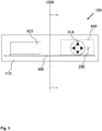
- FIG. 3 3 shows a front view of an exemplary embodiment of an on-board unit 100 according to the invention for a motor vehicle 2100 with optional input 414 and output devices 413 and an optional printer drawer 430.
- an imaginary sectional plane 1000 runs through the on-board unit. so that the in FIGS. 1 . 2 . 4 . 5 and 7 , especially in FIG. 4 , Side views shown are derived from a front view.
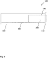
- FIG. 4 shows in a side view an exemplary embodiment of an on-board unit 100 for a motor vehicle 2100 with an optional printer drawer 430.
- an exemplary position of the optional printer drawer 430 can be seen.
- the front 410 forms the end of the on-board unit 100 facing the vehicle occupant and / or the vehicle interior.
- the printer drawer 430 extends from the front 410 far into the interior of the on-board unit 100 and the interior of the housing of the on-board unit 100. Board unit 400 into it, wherein it is located above the horizontal and parallel to the bottom of the on-board unit arranged circuit board of the receiving device 300.
- the GNSS antenna 200 is indicated as a vertical antenna symbol, but this does not mean that the antenna 200 protrudes so far or even out of the plane of the circuit board of the receiving device 300. However, the antenna 200 is disposed on and / or in the circuit board such that it is in the area of the circuit board over which the printer drawer projects.
- FIG. 5 shows a side view of an exemplary embodiment of an on-board unit 100 according to the invention for a motor vehicle 2100 with an exemplary indication of a receiving characteristic 800 of the GNSS antenna 200.
- the illustrated receiving characteristic 800 can be understood as a directional characteristic.
- the exemplary receive characteristic 800 may be recognized as a substantially cardioid-like receive characteristic. The constriction of the cardioid characteristic is in the picture on the right side. On this side is also the front 410.
- the GNSS antenna 200 is arranged to be oriented away from the front of the on-board unit. This corresponds to a substantially horizontal alignment of the antenna.
- FIG. 6 shows a schematic representation of the use of an on-board unit 100 according to the invention in a motor vehicle 2100 for determining a position of the motor vehicle 2100.
- the on-board unit 100 is located in the motor vehicle 2100, which is located between GNSS signals shielding and / or reflecting obstacles 2300, which are indicated as houses.
- the illustrated exemplary situation thus corresponds to a vehicle in an urban canyon, but the principle applies analogously in canyons, mountains, forests, valleys and other situations with obstacles that affect the GNSS reception.
- GNSS satellites 2200 emit GNSS signals 2400 which partially reach the vehicle 2100 and also the on-board unit 100 directly.
- GNSS signals 2400 are reflected at obstacles 2300 and reach the vehicle 2100 and also the on-board unit 100 as reflected GNSS signals 2450. Due to the special feature of the on-board unit according to the invention that the GNSS antenna 200 a linearly polarized antenna, the on-board unit can also receive and process reflected GNSS signals 2450. This makes it possible in a particularly advantageous manner, for example in situations where no or insufficiently strong or for a position determination too few GNSS signals are received directly from an on-board unit that taking into account reflected GNSS signals still a position determination is reached. Such an on-board unit can also determine a position of the motor vehicle taking into account obstacles located on components of the vehicle or in the vehicle, of easily or multiply reflected GNSS signals.
- FIG. 7 shows a side view of an inventive mounting assembly 500 for installation in a motor vehicle 2100 with an on-board unit 100 and a mounting frame 550, which surrounds the on-board unit 100.
- the GNSS antenna 200 is arranged on the side facing towards the vehicle occupant and / or the vehicle interior side or half of the on-board unit 100 such that it is located within the area of the on-board unit 100 encompassed by the mounting frame 550.
Landscapes
- Engineering & Computer Science (AREA)
- Remote Sensing (AREA)
- Radar, Positioning & Navigation (AREA)
- Computer Networks & Wireless Communication (AREA)
- Physics & Mathematics (AREA)
- General Physics & Mathematics (AREA)
- Computer Security & Cryptography (AREA)
- Signal Processing (AREA)
- Fittings On The Vehicle Exterior For Carrying Loads, And Devices For Holding Or Mounting Articles (AREA)
- Support Of Aerials (AREA)
Applications Claiming Priority (2)
| Application Number | Priority Date | Filing Date | Title |
|---|---|---|---|
| DE102017202809 | 2017-02-21 | ||
| DE102017202991.9A DE102017202991A1 (de) | 2017-02-21 | 2017-02-23 | On-Board-Unit für ein Kraftfahrzeug mit einer GNSS-Antenne und einer GNSS-Empfangsvorrichtung zur Ermittlung der Position des Kraftfahrzeugs |
Publications (3)
| Publication Number | Publication Date |
|---|---|
| EP3370087A2 true EP3370087A2 (fr) | 2018-09-05 |
| EP3370087A3 EP3370087A3 (fr) | 2018-09-19 |
| EP3370087B1 EP3370087B1 (fr) | 2021-01-27 |
Family
ID=61244425
Family Applications (1)
| Application Number | Title | Priority Date | Filing Date |
|---|---|---|---|
| EP18157311.4A Active EP3370087B1 (fr) | 2017-02-21 | 2018-02-19 | Unité embarquée pour un véhicule automobile pourvue d'une antenne gnss et d'un dispositif de réception gnss permettant de déterminer la position du véhicule automobile |
Country Status (1)
| Country | Link |
|---|---|
| EP (1) | EP3370087B1 (fr) |
Cited By (1)
| Publication number | Priority date | Publication date | Assignee | Title |
|---|---|---|---|---|
| DE102023210521A1 (de) * | 2023-10-25 | 2025-04-30 | Continental Automotive Technologies GmbH | Verwendung eines Tachographen zum Verarbeiten von erfassten Fahrparametern eines Fahrzeugs |
Families Citing this family (1)
| Publication number | Priority date | Publication date | Assignee | Title |
|---|---|---|---|---|
| DE102023203828A1 (de) * | 2023-04-25 | 2024-10-31 | Continental Automotive Technologies GmbH | Kraftfahrzeugeinbauanordnung mit einem Kraftfahrzeugeinbaugerät und mit einem Einbaurahmen |
Family Cites Families (4)
| Publication number | Priority date | Publication date | Assignee | Title |
|---|---|---|---|---|
| JP2003110351A (ja) * | 2001-07-25 | 2003-04-11 | Denso Corp | アンテナ装置 |
| US7142980B1 (en) * | 2004-04-29 | 2006-11-28 | Garmin Ltd. | Vehicle dash-mounted navigation device |
| DE102011013667A1 (de) * | 2010-12-20 | 2012-06-21 | Continental Automotive Gmbh | Bordinformationssystem mit Antenne zum Empfang satellitenbasierter Geopositionsdaten |
| EP2813864A3 (fr) * | 2013-05-24 | 2015-03-11 | O2 Micro, Inc. | Récepteurs et procédés de navigation multimode |
-
2018
- 2018-02-19 EP EP18157311.4A patent/EP3370087B1/fr active Active
Non-Patent Citations (1)
| Title |
|---|
| None |
Cited By (2)
| Publication number | Priority date | Publication date | Assignee | Title |
|---|---|---|---|---|
| DE102023210521A1 (de) * | 2023-10-25 | 2025-04-30 | Continental Automotive Technologies GmbH | Verwendung eines Tachographen zum Verarbeiten von erfassten Fahrparametern eines Fahrzeugs |
| DE102023210521B4 (de) * | 2023-10-25 | 2026-02-19 | Continental Automotive Technologies GmbH | Verwendung eines Tachographen zum Verarbeiten von erfassten Fahrparametern eines Fahrzeugs |
Also Published As
| Publication number | Publication date |
|---|---|
| EP3370087B1 (fr) | 2021-01-27 |
| EP3370087A3 (fr) | 2018-09-19 |
Similar Documents
| Publication | Publication Date | Title |
|---|---|---|
| EP2466682B1 (fr) | Système d'information à bord doté d'une antenne destinée à la réception de données de géolocalisation par satellite | |
| EP2422214B1 (fr) | Dispositif détecteur pour systèmes d'aide à la conduite dans des véhicules à moteur | |
| DE102010063038B4 (de) | Fahrzeug-Kombiantennenvorrichtung | |
| DE20320216U1 (de) | Laserscanner | |
| EP2470860A1 (fr) | Dispositif de balayage à laser destiné au montage sur la galerie de toit d'un véhicule | |
| EP2877897B1 (fr) | Procédé pour aligner deux éléments d'acquisition d'image d'un système de prise de vue stéréoscopique | |
| DE102013102820A1 (de) | Stereokameramodul sowie Verfahren zur Herstellung | |
| EP2466552B1 (fr) | Système d'information à bord doté d'une antenne mobile | |
| EP2619608A1 (fr) | Dispositif de localisation embarqué dans un véhicule à moteur et procédé de fusion des informations | |
| DE102016102904A1 (de) | Fahrzeugkamerasystem, Objektivmodul eines Fahrzeugkamerasystems und Verfahren zur Herstellung eines Fahrzeugkamerasystems | |
| DE102017202991A1 (de) | On-Board-Unit für ein Kraftfahrzeug mit einer GNSS-Antenne und einer GNSS-Empfangsvorrichtung zur Ermittlung der Position des Kraftfahrzeugs | |
| EP3370087B1 (fr) | Unité embarquée pour un véhicule automobile pourvue d'une antenne gnss et d'un dispositif de réception gnss permettant de déterminer la position du véhicule automobile | |
| DE102013106769A1 (de) | Fahrtenschreiber mit der Spurhalte- und Kollisionswarnfunktion | |
| DE102017214020A1 (de) | Kraftfahrzeug mit mehreren Radarsensoren zur Umfelderfassung | |
| DE10012273B4 (de) | Anlage zur messtechnischen räumlichen 3D-Lageerfassung von Oberflächenpunkten | |
| DE10255549A1 (de) | Antennensystem für ein Kraftfahrzeug | |
| DE19714600A1 (de) | Ortungsvorrichtung für Fahrzeuge | |
| EP2565580A1 (fr) | Procédé de détermination d'une dimension d'un objet dans un environnement d'un véhicule ainsi que dispositif correspondant et véhicule avec un tel dispositif | |
| DE102020113188B3 (de) | Kraftfahrzeug mit einem Fahrzeugdach | |
| DE202020005490U1 (de) | Fahrzeugscheibe | |
| DE102019100989A1 (de) | Kraftfahrzeug und Verfahren zum Betrieb von Radarsensoren in einem Kraftfahrzeug | |
| DE102015002158A1 (de) | Verfahren zur Ermittlung einer Verkehrsdichteinformation in einem Kraftfahrzeug und Kraftfahrzeug | |
| DE102023136169B4 (de) | Montageschiene für ein fahrzeug und fahrzeug | |
| EP3136124A1 (fr) | Procédé pour mettre en service des capteurs radar dans un véhicule à moteur et véhicule à moteur | |
| DE102024208589A1 (de) | Verfahren und Vorrichtung zum Bestimmen der Position und/oder der Ausrichtung eines Kalibriertools in Bezug auf einen Fahrzeugumfeldsensor |
Legal Events
| Date | Code | Title | Description |
|---|---|---|---|
| PUAI | Public reference made under article 153(3) epc to a published international application that has entered the european phase |
Free format text: ORIGINAL CODE: 0009012 |
|
| STAA | Information on the status of an ep patent application or granted ep patent |
Free format text: STATUS: THE APPLICATION HAS BEEN PUBLISHED |
|
| PUAL | Search report despatched |
Free format text: ORIGINAL CODE: 0009013 |
|
| AK | Designated contracting states |
Kind code of ref document: A2 Designated state(s): AL AT BE BG CH CY CZ DE DK EE ES FI FR GB GR HR HU IE IS IT LI LT LU LV MC MK MT NL NO PL PT RO RS SE SI SK SM TR |
|
| AX | Request for extension of the european patent |
Extension state: BA ME |
|
| AK | Designated contracting states |
Kind code of ref document: A3 Designated state(s): AL AT BE BG CH CY CZ DE DK EE ES FI FR GB GR HR HU IE IS IT LI LT LU LV MC MK MT NL NO PL PT RO RS SE SI SK SM TR |
|
| AX | Request for extension of the european patent |
Extension state: BA ME |
|
| RIC1 | Information provided on ipc code assigned before grant |
Ipc: G01S 19/33 20100101ALI20180813BHEP Ipc: G01S 19/42 20100101ALI20180813BHEP Ipc: G01S 19/35 20100101AFI20180813BHEP Ipc: H01Q 1/32 20060101ALI20180813BHEP |
|
| STAA | Information on the status of an ep patent application or granted ep patent |
Free format text: STATUS: REQUEST FOR EXAMINATION WAS MADE |
|
| 17P | Request for examination filed |
Effective date: 20190319 |
|
| RBV | Designated contracting states (corrected) |
Designated state(s): AL AT BE BG CH CY CZ DE DK EE ES FI FR GB GR HR HU IE IS IT LI LT LU LV MC MK MT NL NO PL PT RO RS SE SI SK SM TR |
|
| RIC1 | Information provided on ipc code assigned before grant |
Ipc: G01S 19/33 20100101ALI20200604BHEP Ipc: G01S 19/35 20100101AFI20200604BHEP Ipc: G01S 19/42 20100101ALI20200604BHEP Ipc: H01Q 1/32 20060101ALI20200604BHEP |
|
| GRAP | Despatch of communication of intention to grant a patent |
Free format text: ORIGINAL CODE: EPIDOSNIGR1 |
|
| STAA | Information on the status of an ep patent application or granted ep patent |
Free format text: STATUS: GRANT OF PATENT IS INTENDED |
|
| INTG | Intention to grant announced |
Effective date: 20200716 |
|
| GRAJ | Information related to disapproval of communication of intention to grant by the applicant or resumption of examination proceedings by the epo deleted |
Free format text: ORIGINAL CODE: EPIDOSDIGR1 |
|
| STAA | Information on the status of an ep patent application or granted ep patent |
Free format text: STATUS: REQUEST FOR EXAMINATION WAS MADE |
|
| INTC | Intention to grant announced (deleted) | ||
| GRAP | Despatch of communication of intention to grant a patent |
Free format text: ORIGINAL CODE: EPIDOSNIGR1 |
|
| STAA | Information on the status of an ep patent application or granted ep patent |
Free format text: STATUS: GRANT OF PATENT IS INTENDED |
|
| INTG | Intention to grant announced |
Effective date: 20201001 |
|
| GRAS | Grant fee paid |
Free format text: ORIGINAL CODE: EPIDOSNIGR3 |
|
| GRAA | (expected) grant |
Free format text: ORIGINAL CODE: 0009210 |
|
| STAA | Information on the status of an ep patent application or granted ep patent |
Free format text: STATUS: THE PATENT HAS BEEN GRANTED |
|
| AK | Designated contracting states |
Kind code of ref document: B1 Designated state(s): AL AT BE BG CH CY CZ DE DK EE ES FI FR GB GR HR HU IE IS IT LI LT LU LV MC MK MT NL NO PL PT RO RS SE SI SK SM TR |
|
| REG | Reference to a national code |
Ref country code: GB Ref legal event code: FG4D Free format text: NOT ENGLISH |
|
| REG | Reference to a national code |
Ref country code: CH Ref legal event code: EP |
|
| REG | Reference to a national code |
Ref country code: AT Ref legal event code: REF Ref document number: 1358872 Country of ref document: AT Kind code of ref document: T Effective date: 20210215 |
|
| REG | Reference to a national code |
Ref country code: IE Ref legal event code: FG4D Free format text: LANGUAGE OF EP DOCUMENT: GERMAN |
|
| REG | Reference to a national code |
Ref country code: DE Ref legal event code: R096 Ref document number: 502018003753 Country of ref document: DE |
|
| REG | Reference to a national code |
Ref country code: SE Ref legal event code: TRGR |
|
| REG | Reference to a national code |
Ref country code: NL Ref legal event code: MP Effective date: 20210127 |
|
| REG | Reference to a national code |
Ref country code: LT Ref legal event code: MG9D |
|
| PG25 | Lapsed in a contracting state [announced via postgrant information from national office to epo] |
Ref country code: LT Free format text: LAPSE BECAUSE OF FAILURE TO SUBMIT A TRANSLATION OF THE DESCRIPTION OR TO PAY THE FEE WITHIN THE PRESCRIBED TIME-LIMIT Effective date: 20210127 Ref country code: BG Free format text: LAPSE BECAUSE OF FAILURE TO SUBMIT A TRANSLATION OF THE DESCRIPTION OR TO PAY THE FEE WITHIN THE PRESCRIBED TIME-LIMIT Effective date: 20210427 Ref country code: HR Free format text: LAPSE BECAUSE OF FAILURE TO SUBMIT A TRANSLATION OF THE DESCRIPTION OR TO PAY THE FEE WITHIN THE PRESCRIBED TIME-LIMIT Effective date: 20210127 Ref country code: FI Free format text: LAPSE BECAUSE OF FAILURE TO SUBMIT A TRANSLATION OF THE DESCRIPTION OR TO PAY THE FEE WITHIN THE PRESCRIBED TIME-LIMIT Effective date: 20210127 Ref country code: GR Free format text: LAPSE BECAUSE OF FAILURE TO SUBMIT A TRANSLATION OF THE DESCRIPTION OR TO PAY THE FEE WITHIN THE PRESCRIBED TIME-LIMIT Effective date: 20210428 Ref country code: NO Free format text: LAPSE BECAUSE OF FAILURE TO SUBMIT A TRANSLATION OF THE DESCRIPTION OR TO PAY THE FEE WITHIN THE PRESCRIBED TIME-LIMIT Effective date: 20210427 Ref country code: PT Free format text: LAPSE BECAUSE OF FAILURE TO SUBMIT A TRANSLATION OF THE DESCRIPTION OR TO PAY THE FEE WITHIN THE PRESCRIBED TIME-LIMIT Effective date: 20210527 |
|
| PG25 | Lapsed in a contracting state [announced via postgrant information from national office to epo] |
Ref country code: RS Free format text: LAPSE BECAUSE OF FAILURE TO SUBMIT A TRANSLATION OF THE DESCRIPTION OR TO PAY THE FEE WITHIN THE PRESCRIBED TIME-LIMIT Effective date: 20210127 Ref country code: PL Free format text: LAPSE BECAUSE OF FAILURE TO SUBMIT A TRANSLATION OF THE DESCRIPTION OR TO PAY THE FEE WITHIN THE PRESCRIBED TIME-LIMIT Effective date: 20210127 Ref country code: LV Free format text: LAPSE BECAUSE OF FAILURE TO SUBMIT A TRANSLATION OF THE DESCRIPTION OR TO PAY THE FEE WITHIN THE PRESCRIBED TIME-LIMIT Effective date: 20210127 |
|
| PG25 | Lapsed in a contracting state [announced via postgrant information from national office to epo] |
Ref country code: IS Free format text: LAPSE BECAUSE OF FAILURE TO SUBMIT A TRANSLATION OF THE DESCRIPTION OR TO PAY THE FEE WITHIN THE PRESCRIBED TIME-LIMIT Effective date: 20210527 |
|
| REG | Reference to a national code |
Ref country code: BE Ref legal event code: MM Effective date: 20210228 |
|
| REG | Reference to a national code |
Ref country code: DE Ref legal event code: R097 Ref document number: 502018003753 Country of ref document: DE |
|
| PG25 | Lapsed in a contracting state [announced via postgrant information from national office to epo] |
Ref country code: CH Free format text: LAPSE BECAUSE OF NON-PAYMENT OF DUE FEES Effective date: 20210228 Ref country code: SM Free format text: LAPSE BECAUSE OF FAILURE TO SUBMIT A TRANSLATION OF THE DESCRIPTION OR TO PAY THE FEE WITHIN THE PRESCRIBED TIME-LIMIT Effective date: 20210127 Ref country code: CZ Free format text: LAPSE BECAUSE OF FAILURE TO SUBMIT A TRANSLATION OF THE DESCRIPTION OR TO PAY THE FEE WITHIN THE PRESCRIBED TIME-LIMIT Effective date: 20210127 Ref country code: EE Free format text: LAPSE BECAUSE OF FAILURE TO SUBMIT A TRANSLATION OF THE DESCRIPTION OR TO PAY THE FEE WITHIN THE PRESCRIBED TIME-LIMIT Effective date: 20210127 Ref country code: MC Free format text: LAPSE BECAUSE OF FAILURE TO SUBMIT A TRANSLATION OF THE DESCRIPTION OR TO PAY THE FEE WITHIN THE PRESCRIBED TIME-LIMIT Effective date: 20210127 Ref country code: LI Free format text: LAPSE BECAUSE OF NON-PAYMENT OF DUE FEES Effective date: 20210228 Ref country code: LU Free format text: LAPSE BECAUSE OF NON-PAYMENT OF DUE FEES Effective date: 20210219 |
|
| PG25 | Lapsed in a contracting state [announced via postgrant information from national office to epo] |
Ref country code: RO Free format text: LAPSE BECAUSE OF FAILURE TO SUBMIT A TRANSLATION OF THE DESCRIPTION OR TO PAY THE FEE WITHIN THE PRESCRIBED TIME-LIMIT Effective date: 20210127 Ref country code: DK Free format text: LAPSE BECAUSE OF FAILURE TO SUBMIT A TRANSLATION OF THE DESCRIPTION OR TO PAY THE FEE WITHIN THE PRESCRIBED TIME-LIMIT Effective date: 20210127 Ref country code: SK Free format text: LAPSE BECAUSE OF FAILURE TO SUBMIT A TRANSLATION OF THE DESCRIPTION OR TO PAY THE FEE WITHIN THE PRESCRIBED TIME-LIMIT Effective date: 20210127 |
|
| PLBE | No opposition filed within time limit |
Free format text: ORIGINAL CODE: 0009261 |
|
| STAA | Information on the status of an ep patent application or granted ep patent |
Free format text: STATUS: NO OPPOSITION FILED WITHIN TIME LIMIT |
|
| 26N | No opposition filed |
Effective date: 20211028 |
|
| PG25 | Lapsed in a contracting state [announced via postgrant information from national office to epo] |
Ref country code: AL Free format text: LAPSE BECAUSE OF FAILURE TO SUBMIT A TRANSLATION OF THE DESCRIPTION OR TO PAY THE FEE WITHIN THE PRESCRIBED TIME-LIMIT Effective date: 20210127 Ref country code: ES Free format text: LAPSE BECAUSE OF FAILURE TO SUBMIT A TRANSLATION OF THE DESCRIPTION OR TO PAY THE FEE WITHIN THE PRESCRIBED TIME-LIMIT Effective date: 20210127 Ref country code: IE Free format text: LAPSE BECAUSE OF NON-PAYMENT OF DUE FEES Effective date: 20210219 |
|
| PG25 | Lapsed in a contracting state [announced via postgrant information from national office to epo] |
Ref country code: SI Free format text: LAPSE BECAUSE OF FAILURE TO SUBMIT A TRANSLATION OF THE DESCRIPTION OR TO PAY THE FEE WITHIN THE PRESCRIBED TIME-LIMIT Effective date: 20210127 |
|
| PG25 | Lapsed in a contracting state [announced via postgrant information from national office to epo] |
Ref country code: IT Free format text: LAPSE BECAUSE OF FAILURE TO SUBMIT A TRANSLATION OF THE DESCRIPTION OR TO PAY THE FEE WITHIN THE PRESCRIBED TIME-LIMIT Effective date: 20210127 |
|
| PG25 | Lapsed in a contracting state [announced via postgrant information from national office to epo] |
Ref country code: IS Free format text: LAPSE BECAUSE OF FAILURE TO SUBMIT A TRANSLATION OF THE DESCRIPTION OR TO PAY THE FEE WITHIN THE PRESCRIBED TIME-LIMIT Effective date: 20210527 |
|
| REG | Reference to a national code |
Ref country code: DE Ref legal event code: R081 Ref document number: 502018003753 Country of ref document: DE Owner name: CONTINENTAL AUTOMOTIVE TECHNOLOGIES GMBH, DE Free format text: FORMER OWNER: CONTINENTAL AUTOMOTIVE GMBH, 30165 HANNOVER, DE Ref country code: DE Ref legal event code: R081 Ref document number: 502018003753 Country of ref document: DE Owner name: AUMOVIO GERMANY GMBH, DE Free format text: FORMER OWNER: CONTINENTAL AUTOMOTIVE GMBH, 30165 HANNOVER, DE |
|
| PG25 | Lapsed in a contracting state [announced via postgrant information from national office to epo] |
Ref country code: BE Free format text: LAPSE BECAUSE OF NON-PAYMENT OF DUE FEES Effective date: 20210228 |
|
| GBPC | Gb: european patent ceased through non-payment of renewal fee |
Effective date: 20220219 |
|
| PG25 | Lapsed in a contracting state [announced via postgrant information from national office to epo] |
Ref country code: GB Free format text: LAPSE BECAUSE OF NON-PAYMENT OF DUE FEES Effective date: 20220219 |
|
| P01 | Opt-out of the competence of the unified patent court (upc) registered |
Effective date: 20230522 |
|
| PG25 | Lapsed in a contracting state [announced via postgrant information from national office to epo] |
Ref country code: NL Free format text: LAPSE BECAUSE OF NON-PAYMENT OF DUE FEES Effective date: 20210127 Ref country code: CY Free format text: LAPSE BECAUSE OF FAILURE TO SUBMIT A TRANSLATION OF THE DESCRIPTION OR TO PAY THE FEE WITHIN THE PRESCRIBED TIME-LIMIT Effective date: 20210127 |
|
| PG25 | Lapsed in a contracting state [announced via postgrant information from national office to epo] |
Ref country code: HU Free format text: LAPSE BECAUSE OF FAILURE TO SUBMIT A TRANSLATION OF THE DESCRIPTION OR TO PAY THE FEE WITHIN THE PRESCRIBED TIME-LIMIT; INVALID AB INITIO Effective date: 20180219 |
|
| REG | Reference to a national code |
Ref country code: DE Ref legal event code: R081 Ref document number: 502018003753 Country of ref document: DE Owner name: CONTINENTAL AUTOMOTIVE TECHNOLOGIES GMBH, DE Free format text: FORMER OWNER: CONTINENTAL AUTOMOTIVE TECHNOLOGIES GMBH, 30165 HANNOVER, DE Ref country code: DE Ref legal event code: R081 Ref document number: 502018003753 Country of ref document: DE Owner name: AUMOVIO GERMANY GMBH, DE Free format text: FORMER OWNER: CONTINENTAL AUTOMOTIVE TECHNOLOGIES GMBH, 30165 HANNOVER, DE |
|
| REG | Reference to a national code |
Ref country code: AT Ref legal event code: MM01 Ref document number: 1358872 Country of ref document: AT Kind code of ref document: T Effective date: 20230219 |
|
| PG25 | Lapsed in a contracting state [announced via postgrant information from national office to epo] |
Ref country code: AT Free format text: LAPSE BECAUSE OF NON-PAYMENT OF DUE FEES Effective date: 20230219 |
|
| PG25 | Lapsed in a contracting state [announced via postgrant information from national office to epo] |
Ref country code: MK Free format text: LAPSE BECAUSE OF FAILURE TO SUBMIT A TRANSLATION OF THE DESCRIPTION OR TO PAY THE FEE WITHIN THE PRESCRIBED TIME-LIMIT Effective date: 20210127 Ref country code: AT Free format text: LAPSE BECAUSE OF NON-PAYMENT OF DUE FEES Effective date: 20230219 |
|
| PG25 | Lapsed in a contracting state [announced via postgrant information from national office to epo] |
Ref country code: TR Free format text: LAPSE BECAUSE OF FAILURE TO SUBMIT A TRANSLATION OF THE DESCRIPTION OR TO PAY THE FEE WITHIN THE PRESCRIBED TIME-LIMIT Effective date: 20210127 |
|
| PG25 | Lapsed in a contracting state [announced via postgrant information from national office to epo] |
Ref country code: MT Free format text: LAPSE BECAUSE OF FAILURE TO SUBMIT A TRANSLATION OF THE DESCRIPTION OR TO PAY THE FEE WITHIN THE PRESCRIBED TIME-LIMIT Effective date: 20210127 |
|
| REG | Reference to a national code |
Ref country code: DE Ref legal event code: R081 Ref document number: 502018003753 Country of ref document: DE Owner name: AUMOVIO GERMANY GMBH, DE Free format text: FORMER OWNER: CONTINENTAL AUTOMOTIVE TECHNOLOGIES GMBH, 30175 HANNOVER, DE |
|
| PGFP | Annual fee paid to national office [announced via postgrant information from national office to epo] |
Ref country code: SE Payment date: 20260223 Year of fee payment: 9 |
|
| PGFP | Annual fee paid to national office [announced via postgrant information from national office to epo] |
Ref country code: DE Payment date: 20260228 Year of fee payment: 9 |
|
| PGFP | Annual fee paid to national office [announced via postgrant information from national office to epo] |
Ref country code: AT Payment date: 20260410 Year of fee payment: 5 |
|
| PGFP | Annual fee paid to national office [announced via postgrant information from national office to epo] |
Ref country code: FR Payment date: 20260227 Year of fee payment: 9 |