EP3370097A1 - Verbinder mit seiten- und winkeltoleranz - Google Patents
Verbinder mit seiten- und winkeltoleranz Download PDFInfo
- Publication number
- EP3370097A1 EP3370097A1 EP18159554.7A EP18159554A EP3370097A1 EP 3370097 A1 EP3370097 A1 EP 3370097A1 EP 18159554 A EP18159554 A EP 18159554A EP 3370097 A1 EP3370097 A1 EP 3370097A1
- Authority
- EP
- European Patent Office
- Prior art keywords
- connector
- ferrule
- orifice
- sleeve
- optical contact
- Prior art date
- Legal status (The legal status is an assumption and is not a legal conclusion. Google has not performed a legal analysis and makes no representation as to the accuracy of the status listed.)
- Granted
Links
Images


Classifications
-
- G—PHYSICS
- G02—OPTICS
- G02B—OPTICAL ELEMENTS, SYSTEMS OR APPARATUS
- G02B6/00—Light guides; Structural details of arrangements comprising light guides and other optical elements, e.g. couplings
- G02B6/24—Coupling light guides
- G02B6/36—Mechanical coupling means
- G02B6/38—Mechanical coupling means having fibre to fibre mating means
- G02B6/3807—Dismountable connectors, i.e. comprising plugs
- G02B6/3873—Connectors using guide surfaces for aligning ferrule ends, e.g. tubes, sleeves, V-grooves, rods, pins, balls
- G02B6/3874—Connectors using guide surfaces for aligning ferrule ends, e.g. tubes, sleeves, V-grooves, rods, pins, balls using tubes, sleeves to align ferrules
- G02B6/3875—Floatingly supported sleeves
-
- G—PHYSICS
- G02—OPTICS
- G02B—OPTICAL ELEMENTS, SYSTEMS OR APPARATUS
- G02B6/00—Light guides; Structural details of arrangements comprising light guides and other optical elements, e.g. couplings
- G02B6/24—Coupling light guides
- G02B6/36—Mechanical coupling means
- G02B6/38—Mechanical coupling means having fibre to fibre mating means
- G02B6/3807—Dismountable connectors, i.e. comprising plugs
- G02B6/3869—Mounting ferrules to connector body, i.e. plugs
-
- G—PHYSICS
- G02—OPTICS
- G02B—OPTICAL ELEMENTS, SYSTEMS OR APPARATUS
- G02B6/00—Light guides; Structural details of arrangements comprising light guides and other optical elements, e.g. couplings
- G02B6/24—Coupling light guides
- G02B6/26—Optical coupling means
- G02B6/32—Optical coupling means having lens focusing means positioned between opposed fibre ends
Definitions
- the invention relates generally to fiber-optic systems. More specifically, the invention relates to a multi-ferrule connector having lateral and angular tolerance.
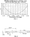
- Fig. 1 shows a sensitivity graph of the modeled loss addition caused by angular tilt between an EB SM pin and socket.
- a SM EB pin terminus 201 which is about 20 mm long including the crimp eyelet is mated to a SM EB socket 202.
- SM connector expanded beam (EB) design that will compensate for angular tilt and lateral offset without the preparation of exotic and complicated parts.
- the present invention fulfills this need among others.
- the above-identified problem is avoided by disposing the sleeve on the ferrule forward of the connector housing such that a gap is defined between the ferrule and the connector housing at the orifice through which the ferrule extends from the connector housing.
- the gap is roughly the size of the sleeve which conventionally is disposed around the ferrule in the orifice. The gap is sufficient to allow the ferrule to move within the orifice angularly and laterally with respect to the housing.
- the invention in one embodiment, relates to a connector comprising a housing having one or more cavities defined therein, and a front face with one or more orifices defined therein. Each of the cavities has an axis. Each of the orifices corresponds to one of the cavities and has an inner first diameter.
- the connector also comprises an optical contact at least partially disposed in one of the cavities. The optical contact comprises at least a ferrule extending from the cavity through the orifice, and defining at least one borehole for receiving a fiber (not shown). The ferrule has a constant outside second diameter along its length.
- the connector also comprises a ferrule holder having a front end connected to the ferrule behind the orifice.
- a sleeve is disposed around a portion the ferrule and extends from a point forward of the orifice to beyond a front end of the ferrule.
- a lens for example, a ball lens, is disposed at least partially in the sleeve and forward of the front face. In one embodiment, the lens contacts the fiber in the ferrule.
- the above-identified problem is avoided by disposing the sleeve on the ferrule forward of the connector housing such that a gap is defined between the ferrule and the connector housing at the orifice through which the ferrule extends from the connector housing.
- the gap is roughly the size of the sleeve which conventionally is disposed around the ferrule in the orifice. The gap is sufficient to allow the ferrule to move within the orifice angularly and laterally with respect to the housing.
- the invention in one embodiment, relates to a connector comprising a housing having one or more cavities defined therein, and a front face with one or more orifices defined therein. Each of the cavities has an axis. Each of the orifices corresponds to one of the cavities and has an inner first diameter.
- the connector also comprises an optical contact at least partially disposed in one of the cavities. The optical contact comprises at least a ferrule extending from the cavity through the orifice, and defining at least one borehole for receiving a fiber (not shown). The ferrule has a constant outside second diameter along its length.
- the connector also comprises a ferrule holder having a front end connected to the ferrule behind the orifice.
- a sleeve is disposed around a portion the ferrule and extends from a point forward of the orifice to beyond a front end of the ferrule.
- a lens for example, a ball lens, is disposed at least partially in the sleeve and forward of the front face. In one embodiment, the lens contacts the fiber in the ferrule.
- the present invention relates to a connector system comprising, for example, two connectors as defined above, and an outer sleeve, wherein a portion of the sleeve of each connector is disposed in the outer sleeve such that the lens of each connector are optically coupled.
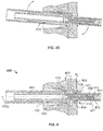
- the connector 400 has a front and rear orientation or origination, and is configured to mate with a mating connector (not shown).
- the connector comprises a housing 401 having one or more cavities 402 defined therein, and a front face 403 with one or more orifices 404 defined therein.
- Each of the cavities 402 has an axis 402a.
- Each of the orifices 404 corresponds to one of the cavities and has an inner first diameter d1.
- the connector 400 also comprises an optical contact 405 at least partially disposed in one of the cavities 402.
- the optical contact 405 comprises at least a ferrule 406 extending from the cavity 402 through the orifice 404, and defining at least one borehole 407 for receiving a fiber (not shown).
- the ferrule has a constant outside second diameter d2 along its length. The second diameter d2 is less than the first diameter d1 such that a gap 408 is defined between the ferrule 406 and the inner first diameter of the orifice 404 to allow the ferrule to move within the orifice angularly and laterally with respect to the axis.
- the connector also comprises a ferrule holder 409 having a front end 410 connected to the ferrule behind the orifice.
- a sleeve 411 is disposed around a portion the ferrule 406 and extends from a point 412 forward of the orifice 404 to beyond a front end 413 of the ferrule.
- a lens 414 for example a ball lens, is disposed at least partially in the sleeve 411 and forward of the front face 403. In one embodiment, the lens 414 contacts the fiber in the ferrule.
- an important aspect of the present invention is the tolerance between optical contact and the housing to accommodate axial and lateral misalignment of the optical contact.
- This tolerance can be provided in different ways.
- the axial and lateral accommodation of the optical contact and the housing 401 is achieved by a gap 408 between the outside of the orifice 404 as defined in the front face 403. As shown in the embodiment of Fig. 4 , this gap is defined between the first diameter d1, and the second diameter d2.
- the gap 408 can vary according to application, although, preferably, it is at least as wide as the thickness of the sleeve 411 such that the optical contact can be assembled first, and then pushed through the orifice 404 during assembly of the connector.
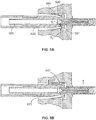
- Fig. 3a shows a prior art connector in which there is essentially no gap between the sleeve 311 and the front face 303 through the orifice 304 a as indicated by the arrows. Because there is no gap between the sleeve 311 and the front face 303 through the orifice 304, there is very little, if any, accommodation for lateral misalignment or axial misalignment.
- the lateral and axial accommodation of the optical contact in the housing is shown respectively.
- the optical contact 405 is moved laterally until the ferrule 406 contacts the top portion of the inner diameter of the orifice 404.
- the gap 408 (as shown in Fig. 4 ) can accommodate axial misalignment as shown in Fig. 3c .
- the optical contact 405 is angled slightly clockwise with respect to housing.
- the gap 408 can be configured to accommodate the required degree of angular misalignment or lateral offset.
- the degree of lateral and angular offset that can be accommodated is dictated by a number of features, including, the gap 408-i.e., the distance between d1 and d2 as shown in Fig. 4 .
- the first diameter d1 of the orifice can vary according to the application, in one embodiment, it is essentially the same as a standard connector, thereby reducing inventory requirements and avoiding the need to retool.
- the gap 408 is achieved by reducing the outer diameter d2 of the optical contact. Although this can be achieved by reducing the diameter of the ferrule, generally, although not necessarily, such a configuration is not preferred because it tends to weaken the ferrule assembly.
- the outer dimeter d2 is reduced by shortening the sleeve 411 such that it does not extend into the orifice 404.
- the sleeve extends from a point 412 in front of the front face 403 to beyond the ferrule as shown in Fig. 3 .
- the point is sufficiently forward of the orifice such that the sleeve does not contact the front face when the optical contact is laterally misaligned as shown in Fig. 3b , or angularly misaligned relative to the axis 402a as shown in Fig. 3c .
- the invention also accommodates lateral and angular misalignment of the optical contact by providing an optical contact with a wide shoulder 530 to accommodate the lateral movement of resilient members 540 across the shoulder 530 during angular and lateral misalignment as shown in Fig. 5a and 5b .
- one effect of the resilient fingers is to center the optical contact in its cavity.
- each retainer mechanism can have anywhere from 2 to 6 fingers in a circular arrangement applying a symmetrical force onto the pin barrel. Therefore, depending on the number of fingers, their material and their flexibility, they will resist the natural alignment conformance of the optical contact with an offset socket. This is illustrated in Fig. 3a and 3b where the fingers on one side are more deflected than on the opposed side. The resistance force will be proportional with the amount of deflection.
- the optical contact 520 shown is a slightly modified version of the optical contact 405 shown in Fig. 4 .
- the ferrule holder 505 is modified to widen the shoulder 530 against which resilient members 540 urge to bias the optical contact 520 forward and center in the housing.
- the shoulder 530 defines an annular surface 531 having an inside diameter di and an outside diameter do thus defining the width of the annular surface.
- the shoulder 530 can be made from various, discrete metals/materials or it can be molded as an integral part of the optical contact.
- the width of the annular surface in this embodiment is wider than that of a standard connector. The wider surface allows the resilient members 540 to slide across the annular surface as the optical contact is laterally or angularly offset. For example, as shown in Fig. 5b in which the optical contact 520 is urged upward, the top and bottom resilient members 540 (as orientated in the figure) slide from the center of the annular surface to the inside diameter di and outside diameter do, respectively.
- the width of the annular surface is a matter of design preference.
- the front face has a chamfer 421 around the orifice 404 to allow for angular misalignment of the optical contact in the cavity.
- the leading edge 611 a of the sleeve 611 is chamfered.
- a chamfer on the front edge of the sleeve 611 will provide better guidance and reduce the interferences that can occur during the initial pin/socket alignment.
- the mating process can be further improved if also a lead-in chamfer 660a is added to the receiving alignment/outer sleeve 660.
- the gap and the shoulder facilitate at least 5° angular movement of the optical contact relative to the axis 402a, and in a more particular embodiment, at least 8° angular movement. In one embodiment, the gap and the shoulder facilitate at least 200 ⁇ m micron lateral movement of the optical contact from the axis, and in a more particular embodiment, at least 300 ⁇ m microns lateral movement from the axis.
- the connector of the present invention may also have other traditional features found in other optical connectors.
- the lens 414 comprises a ball lens.
- the ball lens contacts the ferrule fiber as shown in Fig. 4 .
Landscapes
- Physics & Mathematics (AREA)
- General Physics & Mathematics (AREA)
- Optics & Photonics (AREA)
- Mechanical Coupling Of Light Guides (AREA)
- Optical Couplings Of Light Guides (AREA)
Applications Claiming Priority (1)
| Application Number | Priority Date | Filing Date | Title |
|---|---|---|---|
| US15/449,522 US9989708B1 (en) | 2017-03-03 | 2017-03-03 | Connector with lateral and angular tolerance |
Publications (2)
| Publication Number | Publication Date |
|---|---|
| EP3370097A1 true EP3370097A1 (de) | 2018-09-05 |
| EP3370097B1 EP3370097B1 (de) | 2021-02-24 |
Family
ID=61557111
Family Applications (1)
| Application Number | Title | Priority Date | Filing Date |
|---|---|---|---|
| EP18159554.7A Active EP3370097B1 (de) | 2017-03-03 | 2018-03-01 | Verbinder mit seiten- und winkeltoleranz |
Country Status (2)
| Country | Link |
|---|---|
| US (1) | US9989708B1 (de) |
| EP (1) | EP3370097B1 (de) |
Families Citing this family (4)
| Publication number | Priority date | Publication date | Assignee | Title |
|---|---|---|---|---|
| US10866370B2 (en) | 2018-12-12 | 2020-12-15 | Te Connectivity Corporation | Connector with vibration tolerance |
| WO2020209075A1 (ja) * | 2019-04-11 | 2020-10-15 | ソニー株式会社 | 光コネクタ、光ケーブルおよび電子機器 |
| US12152958B2 (en) | 2022-11-11 | 2024-11-26 | Te Connectivity Solutions Gmbh | Test probe for expanded beam connector |
| CN118131410B (zh) * | 2024-05-07 | 2024-07-05 | 成都奥捷通信技术有限公司 | 一种通用型光无源连接器及使用方法 |
Citations (5)
| Publication number | Priority date | Publication date | Assignee | Title |
|---|---|---|---|---|
| US3947182A (en) * | 1974-10-29 | 1976-03-30 | International Telephone & Telegraph Corporation | Fiber optic connector with axial tolerance relief |
| US4747658A (en) * | 1983-03-14 | 1988-05-31 | International Telephone And Telegraph Corporation | Fiber optic contact |
| US20020186931A1 (en) * | 2001-04-20 | 2002-12-12 | Koji Seo | Housing for optical connector and optical connector |
| US9213147B2 (en) | 2011-11-08 | 2015-12-15 | Sabritec | Floating fiber optic pin contact assembly having a ferrule capable of movement within a multi-piece body of the contact assembly |
| US20170052326A1 (en) * | 2015-08-21 | 2017-02-23 | Tyco Electronics Corporation | Expanded beam connector with discrete alignment assembly |
Family Cites Families (1)
| Publication number | Priority date | Publication date | Assignee | Title |
|---|---|---|---|---|
| US9465171B2 (en) * | 2014-06-10 | 2016-10-11 | Tyco Electronics Corporation | Short optical terminus |
-
2017
- 2017-03-03 US US15/449,522 patent/US9989708B1/en active Active
-
2018
- 2018-03-01 EP EP18159554.7A patent/EP3370097B1/de active Active
Patent Citations (5)
| Publication number | Priority date | Publication date | Assignee | Title |
|---|---|---|---|---|
| US3947182A (en) * | 1974-10-29 | 1976-03-30 | International Telephone & Telegraph Corporation | Fiber optic connector with axial tolerance relief |
| US4747658A (en) * | 1983-03-14 | 1988-05-31 | International Telephone And Telegraph Corporation | Fiber optic contact |
| US20020186931A1 (en) * | 2001-04-20 | 2002-12-12 | Koji Seo | Housing for optical connector and optical connector |
| US9213147B2 (en) | 2011-11-08 | 2015-12-15 | Sabritec | Floating fiber optic pin contact assembly having a ferrule capable of movement within a multi-piece body of the contact assembly |
| US20170052326A1 (en) * | 2015-08-21 | 2017-02-23 | Tyco Electronics Corporation | Expanded beam connector with discrete alignment assembly |
Also Published As
| Publication number | Publication date |
|---|---|
| EP3370097B1 (de) | 2021-02-24 |
| US9989708B1 (en) | 2018-06-05 |
Similar Documents
| Publication | Publication Date | Title |
|---|---|---|
| US20240385387A1 (en) | Housing for a fiber optic connector | |
| US8974124B2 (en) | Fiber optic connector | |
| US9977195B2 (en) | Optical fiber connector and ferrule | |
| EP3370097B1 (de) | Verbinder mit seiten- und winkeltoleranz | |
| JP4248401B2 (ja) | 浮遊型コネクタ副組み立て体とそれを含むコネクタ | |
| US5230032A (en) | Abutting tips fiber optic connector and method of making same | |
| US20160131851A1 (en) | Fiber optic connector | |
| US8864390B2 (en) | Optical fiber connector | |
| EP3417326B1 (de) | Faseroptischer kabelverbinder | |
| CN107636505B (zh) | 具有应变消除组件的光纤连接器 | |
| EP0002565B1 (de) | Lichtleiterkupplung | |
| US9465171B2 (en) | Short optical terminus | |
| CN100501474C (zh) | 光纤连接器 | |
| GB1563077A (en) | Connector for light conductive cables | |
| US20210080657A1 (en) | Fiber optic connector for hardware interiors and method of using same | |
| US6688782B1 (en) | Universal ferrule | |
| CN218547062U (zh) | 光模块及其应用的mpo接口组件、跳线组件 | |
| WO2016073266A1 (en) | Fiber optic connector | |
| US20190346635A1 (en) | Fiber optic adapter and fiber optic connector | |
| US6893161B2 (en) | Optical connector device | |
| CN117813534A (zh) | 光连接部件 | |
| AU3231299A (en) | Fiber optic connector having a spring positioner | |
| US5189715A (en) | Optical waveguide connection elements | |
| JP2003294984A (ja) | 光アダプタ |
Legal Events
| Date | Code | Title | Description |
|---|---|---|---|
| PUAI | Public reference made under article 153(3) epc to a published international application that has entered the european phase |
Free format text: ORIGINAL CODE: 0009012 |
|
| STAA | Information on the status of an ep patent application or granted ep patent |
Free format text: STATUS: THE APPLICATION HAS BEEN PUBLISHED |
|
| AK | Designated contracting states |
Kind code of ref document: A1 Designated state(s): AL AT BE BG CH CY CZ DE DK EE ES FI FR GB GR HR HU IE IS IT LI LT LU LV MC MK MT NL NO PL PT RO RS SE SI SK SM TR |
|
| AX | Request for extension of the european patent |
Extension state: BA ME |
|
| STAA | Information on the status of an ep patent application or granted ep patent |
Free format text: STATUS: REQUEST FOR EXAMINATION WAS MADE |
|
| 17P | Request for examination filed |
Effective date: 20190304 |
|
| RBV | Designated contracting states (corrected) |
Designated state(s): AL AT BE BG CH CY CZ DE DK EE ES FI FR GB GR HR HU IE IS IT LI LT LU LV MC MK MT NL NO PL PT RO RS SE SI SK SM TR |
|
| GRAP | Despatch of communication of intention to grant a patent |
Free format text: ORIGINAL CODE: EPIDOSNIGR1 |
|
| STAA | Information on the status of an ep patent application or granted ep patent |
Free format text: STATUS: GRANT OF PATENT IS INTENDED |
|
| RIC1 | Information provided on ipc code assigned before grant |
Ipc: G02B 6/32 20060101ALN20201028BHEP Ipc: G02B 6/38 20060101AFI20201028BHEP |
|
| INTG | Intention to grant announced |
Effective date: 20201120 |
|
| GRAS | Grant fee paid |
Free format text: ORIGINAL CODE: EPIDOSNIGR3 |
|
| GRAA | (expected) grant |
Free format text: ORIGINAL CODE: 0009210 |
|
| STAA | Information on the status of an ep patent application or granted ep patent |
Free format text: STATUS: THE PATENT HAS BEEN GRANTED |
|
| AK | Designated contracting states |
Kind code of ref document: B1 Designated state(s): AL AT BE BG CH CY CZ DE DK EE ES FI FR GB GR HR HU IE IS IT LI LT LU LV MC MK MT NL NO PL PT RO RS SE SI SK SM TR |
|
| REG | Reference to a national code |
Ref country code: CH Ref legal event code: EP |
|
| REG | Reference to a national code |
Ref country code: DE Ref legal event code: R096 Ref document number: 602018012847 Country of ref document: DE |
|
| REG | Reference to a national code |
Ref country code: AT Ref legal event code: REF Ref document number: 1365205 Country of ref document: AT Kind code of ref document: T Effective date: 20210315 |
|
| REG | Reference to a national code |
Ref country code: IE Ref legal event code: FG4D |
|
| REG | Reference to a national code |
Ref country code: LT Ref legal event code: MG9D |
|
| REG | Reference to a national code |
Ref country code: NL Ref legal event code: MP Effective date: 20210224 |
|
| PG25 | Lapsed in a contracting state [announced via postgrant information from national office to epo] |
Ref country code: BG Free format text: LAPSE BECAUSE OF FAILURE TO SUBMIT A TRANSLATION OF THE DESCRIPTION OR TO PAY THE FEE WITHIN THE PRESCRIBED TIME-LIMIT Effective date: 20210524 Ref country code: LT Free format text: LAPSE BECAUSE OF FAILURE TO SUBMIT A TRANSLATION OF THE DESCRIPTION OR TO PAY THE FEE WITHIN THE PRESCRIBED TIME-LIMIT Effective date: 20210224 Ref country code: HR Free format text: LAPSE BECAUSE OF FAILURE TO SUBMIT A TRANSLATION OF THE DESCRIPTION OR TO PAY THE FEE WITHIN THE PRESCRIBED TIME-LIMIT Effective date: 20210224 Ref country code: FI Free format text: LAPSE BECAUSE OF FAILURE TO SUBMIT A TRANSLATION OF THE DESCRIPTION OR TO PAY THE FEE WITHIN THE PRESCRIBED TIME-LIMIT Effective date: 20210224 Ref country code: GR Free format text: LAPSE BECAUSE OF FAILURE TO SUBMIT A TRANSLATION OF THE DESCRIPTION OR TO PAY THE FEE WITHIN THE PRESCRIBED TIME-LIMIT Effective date: 20210525 Ref country code: PT Free format text: LAPSE BECAUSE OF FAILURE TO SUBMIT A TRANSLATION OF THE DESCRIPTION OR TO PAY THE FEE WITHIN THE PRESCRIBED TIME-LIMIT Effective date: 20210624 Ref country code: NO Free format text: LAPSE BECAUSE OF FAILURE TO SUBMIT A TRANSLATION OF THE DESCRIPTION OR TO PAY THE FEE WITHIN THE PRESCRIBED TIME-LIMIT Effective date: 20210524 |
|
| REG | Reference to a national code |
Ref country code: AT Ref legal event code: MK05 Ref document number: 1365205 Country of ref document: AT Kind code of ref document: T Effective date: 20210224 |
|
| PG25 | Lapsed in a contracting state [announced via postgrant information from national office to epo] |
Ref country code: SE Free format text: LAPSE BECAUSE OF FAILURE TO SUBMIT A TRANSLATION OF THE DESCRIPTION OR TO PAY THE FEE WITHIN THE PRESCRIBED TIME-LIMIT Effective date: 20210224 Ref country code: LV Free format text: LAPSE BECAUSE OF FAILURE TO SUBMIT A TRANSLATION OF THE DESCRIPTION OR TO PAY THE FEE WITHIN THE PRESCRIBED TIME-LIMIT Effective date: 20210224 Ref country code: RS Free format text: LAPSE BECAUSE OF FAILURE TO SUBMIT A TRANSLATION OF THE DESCRIPTION OR TO PAY THE FEE WITHIN THE PRESCRIBED TIME-LIMIT Effective date: 20210224 Ref country code: NL Free format text: LAPSE BECAUSE OF FAILURE TO SUBMIT A TRANSLATION OF THE DESCRIPTION OR TO PAY THE FEE WITHIN THE PRESCRIBED TIME-LIMIT Effective date: 20210224 Ref country code: PL Free format text: LAPSE BECAUSE OF FAILURE TO SUBMIT A TRANSLATION OF THE DESCRIPTION OR TO PAY THE FEE WITHIN THE PRESCRIBED TIME-LIMIT Effective date: 20210224 |
|
| PG25 | Lapsed in a contracting state [announced via postgrant information from national office to epo] |
Ref country code: IS Free format text: LAPSE BECAUSE OF FAILURE TO SUBMIT A TRANSLATION OF THE DESCRIPTION OR TO PAY THE FEE WITHIN THE PRESCRIBED TIME-LIMIT Effective date: 20210624 |
|
| PG25 | Lapsed in a contracting state [announced via postgrant information from national office to epo] |
Ref country code: CZ Free format text: LAPSE BECAUSE OF FAILURE TO SUBMIT A TRANSLATION OF THE DESCRIPTION OR TO PAY THE FEE WITHIN THE PRESCRIBED TIME-LIMIT Effective date: 20210224 Ref country code: EE Free format text: LAPSE BECAUSE OF FAILURE TO SUBMIT A TRANSLATION OF THE DESCRIPTION OR TO PAY THE FEE WITHIN THE PRESCRIBED TIME-LIMIT Effective date: 20210224 Ref country code: AT Free format text: LAPSE BECAUSE OF FAILURE TO SUBMIT A TRANSLATION OF THE DESCRIPTION OR TO PAY THE FEE WITHIN THE PRESCRIBED TIME-LIMIT Effective date: 20210224 Ref country code: SM Free format text: LAPSE BECAUSE OF FAILURE TO SUBMIT A TRANSLATION OF THE DESCRIPTION OR TO PAY THE FEE WITHIN THE PRESCRIBED TIME-LIMIT Effective date: 20210224 |
|
| REG | Reference to a national code |
Ref country code: CH Ref legal event code: PL |
|
| REG | Reference to a national code |
Ref country code: DE Ref legal event code: R097 Ref document number: 602018012847 Country of ref document: DE |
|
| PG25 | Lapsed in a contracting state [announced via postgrant information from national office to epo] |
Ref country code: DK Free format text: LAPSE BECAUSE OF FAILURE TO SUBMIT A TRANSLATION OF THE DESCRIPTION OR TO PAY THE FEE WITHIN THE PRESCRIBED TIME-LIMIT Effective date: 20210224 Ref country code: SK Free format text: LAPSE BECAUSE OF FAILURE TO SUBMIT A TRANSLATION OF THE DESCRIPTION OR TO PAY THE FEE WITHIN THE PRESCRIBED TIME-LIMIT Effective date: 20210224 Ref country code: RO Free format text: LAPSE BECAUSE OF FAILURE TO SUBMIT A TRANSLATION OF THE DESCRIPTION OR TO PAY THE FEE WITHIN THE PRESCRIBED TIME-LIMIT Effective date: 20210224 Ref country code: MC Free format text: LAPSE BECAUSE OF FAILURE TO SUBMIT A TRANSLATION OF THE DESCRIPTION OR TO PAY THE FEE WITHIN THE PRESCRIBED TIME-LIMIT Effective date: 20210224 |
|
| REG | Reference to a national code |
Ref country code: BE Ref legal event code: MM Effective date: 20210331 |
|
| PLBE | No opposition filed within time limit |
Free format text: ORIGINAL CODE: 0009261 |
|
| STAA | Information on the status of an ep patent application or granted ep patent |
Free format text: STATUS: NO OPPOSITION FILED WITHIN TIME LIMIT |
|
| PG25 | Lapsed in a contracting state [announced via postgrant information from national office to epo] |
Ref country code: IE Free format text: LAPSE BECAUSE OF NON-PAYMENT OF DUE FEES Effective date: 20210301 Ref country code: ES Free format text: LAPSE BECAUSE OF FAILURE TO SUBMIT A TRANSLATION OF THE DESCRIPTION OR TO PAY THE FEE WITHIN THE PRESCRIBED TIME-LIMIT Effective date: 20210224 Ref country code: LI Free format text: LAPSE BECAUSE OF NON-PAYMENT OF DUE FEES Effective date: 20210331 Ref country code: LU Free format text: LAPSE BECAUSE OF NON-PAYMENT OF DUE FEES Effective date: 20210301 Ref country code: AL Free format text: LAPSE BECAUSE OF FAILURE TO SUBMIT A TRANSLATION OF THE DESCRIPTION OR TO PAY THE FEE WITHIN THE PRESCRIBED TIME-LIMIT Effective date: 20210224 Ref country code: CH Free format text: LAPSE BECAUSE OF NON-PAYMENT OF DUE FEES Effective date: 20210331 |
|
| 26N | No opposition filed |
Effective date: 20211125 |
|
| PG25 | Lapsed in a contracting state [announced via postgrant information from national office to epo] |
Ref country code: SI Free format text: LAPSE BECAUSE OF FAILURE TO SUBMIT A TRANSLATION OF THE DESCRIPTION OR TO PAY THE FEE WITHIN THE PRESCRIBED TIME-LIMIT Effective date: 20210224 |
|
| PG25 | Lapsed in a contracting state [announced via postgrant information from national office to epo] |
Ref country code: IT Free format text: LAPSE BECAUSE OF FAILURE TO SUBMIT A TRANSLATION OF THE DESCRIPTION OR TO PAY THE FEE WITHIN THE PRESCRIBED TIME-LIMIT Effective date: 20210224 |
|
| PG25 | Lapsed in a contracting state [announced via postgrant information from national office to epo] |
Ref country code: IS Free format text: LAPSE BECAUSE OF FAILURE TO SUBMIT A TRANSLATION OF THE DESCRIPTION OR TO PAY THE FEE WITHIN THE PRESCRIBED TIME-LIMIT Effective date: 20210624 |
|
| PG25 | Lapsed in a contracting state [announced via postgrant information from national office to epo] |
Ref country code: BE Free format text: LAPSE BECAUSE OF NON-PAYMENT OF DUE FEES Effective date: 20210331 |
|
| PG25 | Lapsed in a contracting state [announced via postgrant information from national office to epo] |
Ref country code: CY Free format text: LAPSE BECAUSE OF FAILURE TO SUBMIT A TRANSLATION OF THE DESCRIPTION OR TO PAY THE FEE WITHIN THE PRESCRIBED TIME-LIMIT Effective date: 20210224 |
|
| PG25 | Lapsed in a contracting state [announced via postgrant information from national office to epo] |
Ref country code: HU Free format text: LAPSE BECAUSE OF FAILURE TO SUBMIT A TRANSLATION OF THE DESCRIPTION OR TO PAY THE FEE WITHIN THE PRESCRIBED TIME-LIMIT; INVALID AB INITIO Effective date: 20180301 |
|
| PG25 | Lapsed in a contracting state [announced via postgrant information from national office to epo] |
Ref country code: MK Free format text: LAPSE BECAUSE OF FAILURE TO SUBMIT A TRANSLATION OF THE DESCRIPTION OR TO PAY THE FEE WITHIN THE PRESCRIBED TIME-LIMIT Effective date: 20210224 |
|
| PG25 | Lapsed in a contracting state [announced via postgrant information from national office to epo] |
Ref country code: MT Free format text: LAPSE BECAUSE OF FAILURE TO SUBMIT A TRANSLATION OF THE DESCRIPTION OR TO PAY THE FEE WITHIN THE PRESCRIBED TIME-LIMIT Effective date: 20210224 |
|
| REG | Reference to a national code |
Ref country code: GB Ref legal event code: 732E Free format text: REGISTERED BETWEEN 20250731 AND 20250806 |
|
| PG25 | Lapsed in a contracting state [announced via postgrant information from national office to epo] |
Ref country code: TR Free format text: LAPSE BECAUSE OF FAILURE TO SUBMIT A TRANSLATION OF THE DESCRIPTION OR TO PAY THE FEE WITHIN THE PRESCRIBED TIME-LIMIT Effective date: 20210224 |
|
| PGFP | Annual fee paid to national office [announced via postgrant information from national office to epo] |
Ref country code: FR Payment date: 20251231 Year of fee payment: 9 |
|
| PGFP | Annual fee paid to national office [announced via postgrant information from national office to epo] |
Ref country code: GB Payment date: 20260106 Year of fee payment: 9 |
|
| PGFP | Annual fee paid to national office [announced via postgrant information from national office to epo] |
Ref country code: DE Payment date: 20260102 Year of fee payment: 9 |