EP3370098A1 - Anpassbare optische linse und kameramodul, herstellungsverfahren und anwendungen davon - Google Patents
Anpassbare optische linse und kameramodul, herstellungsverfahren und anwendungen davon Download PDFInfo
- Publication number
- EP3370098A1 EP3370098A1 EP16858996.8A EP16858996A EP3370098A1 EP 3370098 A1 EP3370098 A1 EP 3370098A1 EP 16858996 A EP16858996 A EP 16858996A EP 3370098 A1 EP3370098 A1 EP 3370098A1
- Authority
- EP
- European Patent Office
- Prior art keywords
- lens
- optical
- adjustable
- camera module
- structural member
- Prior art date
- Legal status (The legal status is an assumption and is not a legal conclusion. Google has not performed a legal analysis and makes no representation as to the accuracy of the status listed.)
- Granted
Links
Images











Classifications
-
- G—PHYSICS
- G02—OPTICS
- G02B—OPTICAL ELEMENTS, SYSTEMS OR APPARATUS
- G02B7/00—Mountings, adjusting means, or light-tight connections, for optical elements
- G02B7/02—Mountings, adjusting means, or light-tight connections, for optical elements for lenses
- G02B7/04—Mountings, adjusting means, or light-tight connections, for optical elements for lenses with mechanism for focusing or varying magnification
- G02B7/10—Mountings, adjusting means, or light-tight connections, for optical elements for lenses with mechanism for focusing or varying magnification by relative axial movement of several lenses, e.g. of varifocal objective lens
-
- G—PHYSICS
- G02—OPTICS
- G02B—OPTICAL ELEMENTS, SYSTEMS OR APPARATUS
- G02B5/00—Optical elements other than lenses
- G02B5/20—Filters
-
- G—PHYSICS
- G02—OPTICS
- G02B—OPTICAL ELEMENTS, SYSTEMS OR APPARATUS
- G02B7/00—Mountings, adjusting means, or light-tight connections, for optical elements
-
- G—PHYSICS
- G02—OPTICS
- G02B—OPTICAL ELEMENTS, SYSTEMS OR APPARATUS
- G02B7/00—Mountings, adjusting means, or light-tight connections, for optical elements
- G02B7/003—Alignment of optical elements
-
- G—PHYSICS
- G02—OPTICS
- G02B—OPTICAL ELEMENTS, SYSTEMS OR APPARATUS
- G02B7/00—Mountings, adjusting means, or light-tight connections, for optical elements
- G02B7/02—Mountings, adjusting means, or light-tight connections, for optical elements for lenses
-
- G—PHYSICS
- G02—OPTICS
- G02B—OPTICAL ELEMENTS, SYSTEMS OR APPARATUS
- G02B7/00—Mountings, adjusting means, or light-tight connections, for optical elements
- G02B7/02—Mountings, adjusting means, or light-tight connections, for optical elements for lenses
- G02B7/023—Mountings, adjusting means, or light-tight connections, for optical elements for lenses permitting adjustment
-
- G—PHYSICS
- G02—OPTICS
- G02B—OPTICAL ELEMENTS, SYSTEMS OR APPARATUS
- G02B7/00—Mountings, adjusting means, or light-tight connections, for optical elements
- G02B7/02—Mountings, adjusting means, or light-tight connections, for optical elements for lenses
- G02B7/025—Mountings, adjusting means, or light-tight connections, for optical elements for lenses using glue
-
- H—ELECTRICITY
- H04—ELECTRIC COMMUNICATION TECHNIQUE
- H04N—PICTORIAL COMMUNICATION, e.g. TELEVISION
- H04N23/00—Cameras or camera modules comprising electronic image sensors; Control thereof
- H04N23/50—Constructional details
- H04N23/55—Optical parts specially adapted for electronic image sensors; Mounting thereof
-
- G—PHYSICS
- G02—OPTICS
- G02B—OPTICAL ELEMENTS, SYSTEMS OR APPARATUS
- G02B13/00—Optical objectives specially designed for the purposes specified below
- G02B13/001—Miniaturised objectives for electronic devices, e.g. portable telephones, webcams, PDAs, small digital cameras
Definitions
- the present invention relates to the field of camera module, and more particularly to an adjustable optical lens and camera module and manufacturing method and applications thereof.
- a camera module related technologies applied to mobile electronic devices for images capturing (e.g. videos or pictures) for the user have been rapidly developed and improved. Meanwhile, the camera module has recently and widely applied to various fields, including health care, safety and security, and industrial production fields, and etc..
- the conventional camera module comprises an optical lens and an optical sensor.
- the optical lens is arranged along a photosensitive path of the optical sensor within a barrel, and that lights reflected from an object can enter an inside of the camera module through the optical lens and be received by the optical sensor to proceed photoelectric conversion, so that images respective to the object can be subsequently captured by the camera module.
- the camera module has been further utilized in all industries and fields, users in the market have demanded strictly more on the imaging quality of the camera module.
- the current camera module in the market can barely fulfill the application needs of the high quality camera module for the market.
- the conventional optical lens usually comprises a plurality of lens which are aligned overlappingly with each other and molded together.
- the central axis line of the optical lens can be affected by a position of the central axis line of each lens.
- the most ideal condition is that the central axis line of each lens is coincided with each other.
- each lens needs to be arranged on the case of optical lens through a gluing or welding process, a position and an inclination of each lens are affected by the gluing and welding material, so that the central axis line of the optical lens has a greater deviation by packaging each overlapped lens in the camera case.
- a camera module related technologies applied to mobile electronic devices for images capturing (e.g. videos or pictures) for the user have been rapidly developed and improved. Meanwhile, the camera module has recently and widely applied to various fields, including health care, safety and security, and industrial production fields, and etc..
- the conventional camera module comprises an optical lens and an optical sensor.
- the optical lens is arranged along a photosensitive path of the optical sensor within a barrel, and that lights reflected from an object can enter an inside of the camera module through the optical lens and be received by the optical sensor to proceed photoelectric conversion, so that images respective to the object can be subsequently captured by the camera module.
- the camera module has been further utilized in all industries and fields, users in the market have demanded strictly more on the imaging quality of the camera module.
- the current camera module in the market can barely fulfill the application needs of the high quality camera module for the market.
- the conventional optical lens usually comprises a plurality of lens which are aligned overlappingly with each other and molded together.
- the central axis line of the optical lens can be affected by a position of the central axis line of each lens.
- the most ideal condition is that the central axis line of each lens is coincided with each other.
- each lens needs to be arranged on the case of optical lens through a gluing or welding process, a position and an inclination of each lens are affected by the gluing and welding material, so that the central axis line of the optical lens has a greater deviation by packaging each overlapped lens in the camera case.
- Regular cellphone camera modules often have blur imaging issue due to tilt of the material or assembling.
- a technology which adjusts the optics path of the camera lens through adjusting a piece or a set of the camera lenses, which means a movable part of the camera lens of the assembled camera module can be adjusted in at least one of the horizontal, vertical, tilt, rotation directions, such that the optical axis of the camera lens can be perpendicular to the chip or within an allowable range of deviance, so as to solve the blur imaging issue.
- the way to better adjust the optical lens and affix it after adjustment to ensure good imaging quality while keeping low cost and easy assembling of the camera module has then become an urgent demand in the field of camera module.
- camera lens is a part to be independently assembled. It includes the structures of a lens cone(including a aperture member), lens(es), spacer ring, stopper, and etc.
- the assembling process includes orderly installing the spacer ring and lens(es) into the lens cone and utilizing glue or stopper to affix the last lens to complete the assembling of the camera lens.
- the assembling tolerance of the above assembling method includes the assembling tolerance of the optical lens and spacer ring and the assembling tolerance of the optical lens and camera lens. Therefore, the assembling tolerance chain of this assembling method is too long, which brings high assembling cost and low accuracy of the assembling position of the optical lens and affects the quality of the camera lens. As a result, the quality of the entire camera module and products that utilize it can be influenced.
- the invention is advantageous in that it provides an adjustable optical lens and camera module and manufacturing method and applications thereof, wherein the adjustable optical lens comprises an optical structural member and at least two optical lenses.
- the optical lenses are overlappingly and spacedly arranged in an internal space of the optical structural member, and the position of at least one of the optical lens in the internal space of the optical structural member is adjustably arranged.
- Another advantage of the invention is to provide an adjustable optical lens and camera module and manufacturing method thereof, wherein the central axis line of the adjustable optical lens is able to be adjusted through changing the position of the optical lens in the internal space of the optical structural member. For example, while the position of the optical lens in the internal space of the optical structural member is adjusted, the central axis lines of the adjustable optical lens and the lens set formed by each lens are coincided, so as to increase the yield rate of the adjustable optical lens.
- Another advantage of the invention is to provide an adjustable optical lens and camera module and manufacturing method and applications thereof, wherein positions of the optical lens of the adjustable optical lens in the internal space of the optical structural member are able be adjusted along at least one direction.
- Another advantage of the invention is to provide an adjustable optical lens and camera module and manufacturing method and applications thereof, wherein the horizontal position of the optical lens of the adjustable optical lens in the internal space of the optical structural member can be adjusted.
- Another advantage of the invention is to provide an adjustable optical lens and camera module and manufacturing method and applications thereof, wherein the vertical position of the optical lens of the adjustable optical lens in the internal space of the optical structural member can be adjusted.
- Another advantage of the invention is to provide an adjustable optical lens and camera module and manufacturing method and applications thereof, wherein the tilt position of the optical lens of the adjustable optical lens in the internal space of the optical structural member can be adjusted.
- Another advantage of the invention is to provide an adjustable optical lens and camera module and manufacturing method and applications thereof, wherein each lens of the adjustable optical lens in the internal space of the optical structural member is able to be adjusted to rotate.
- Another advantage of the invention is to provide an adjustable optical lens and camera module and manufacturing method and applications thereof, wherein the optical structural member has at least one adjustment channels, and when the optical lens are packed in the internal space of the optical structural member to form the adjustable optical lens, the optical lens are arranged in the internal space of the optical structural member which is relative to the adjustment channel, so that the position of the optical lens in the internal space of the optical structural member from the external environment of the optical structural member is able to be adjusted through the adjustment channel, so as to simplify the operation process.
- Another advantage of the invention is to provide an adjustable optical lens and camera module and manufacturing method and applications thereof, in a manufacturing method for the camera module by packaging the adjustable optical lens and an optical sensor with each other, the position of at least one of the optical lens of the adjustable optical lens in the internal space of the optical structural member is able to be adjusted, so as to ensure that the central axis line of the adjustable optical lens of the camera module and the central axis line of the optical sensor are coincided.
- Another advantage of the invention is to provide an adjustable optical lens and camera module and manufacturing method and applications thereof, wherein when the position of the optical lens in the internal space of the optical structural member is adjusted, the adjusted lens is first packed in the optical structural member and the adjustable optical lens and the optical sensor are packed. An offset generated between the adjusted optical lens and the optical sensor can be prevented in this process of packaging the adjustable optical lens and the optical sensor, so as to guarantee the reliability of the camera module.
- Another advantage of the invention is to provide an adjustable optical lens and camera module and manufacturing method and applications thereof, in the process of packaging the camera module, a range of deviation of the central axis line of the adjustable optical lens and the central axis line of the optical sensor can be adjusted within an acceptable range, so as to improve a yield rate and image quality for the camera module.
- Another advantage of the present invention is to provide an adjustable optical lens and camera module and manufacturing method and applications thereof, wherein the adjustable optical lens includes an aperture member.
- the aperture member is arranged on a top position of an optical structural member and is able to be adjusted respective to the position of the optical structural member.
- Another advantage of the present invention is to provide an adjustable camera lens and camera module and manufacturing method and applications thereof, which changes current manufacturing method of camera module by preassembling optical lenses into optical structural member to be adjusted to reach resolution requirement and affixed, so as to form a fixed camera module. This reduces manufacturing procedures and is able to solve current issues of too much tolerance from the assembling with the manufacturing method of camera module and process defect of overlength tolerance chain in the assembling.
- Another advantage of the present invention is to provide an adjustable camera lens and camera module and manufacturing method and applications thereof, which reduces successive testing process, lowers testing cost, and has lower production cost and higher efficiency.
- Another advantage of the invention is to provide an adjustable optical lens and camera module and manufacturing method and applications thereof, wherein positions of the optical lens of the adjustable optical lens in the internal space of the optical structural member are able to be adjusted along at least one direction.
- Another advantage of the invention is to provide an adjustable optical lens and camera module and manufacturing method and applications thereof, wherein a horizontal position of each lens and/or aperture member of the adjustable optical lens in the internal space of the optical structural member is able to be adjusted.
- Another advantage of the invention is to provide an adjustable optical lens and camera module and manufacturing method and applications thereof, wherein a vertical position of each lens and/or aperture member of the adjustable optical lens in the internal space of the optical structural member is able to be adjusted.
- Another advantage of the invention is to provide an adjustable optical lens and camera module and manufacturing method and applications thereof, wherein a tilt position of each lens and/or aperture member of the adjustable optical lens in the internal space of the optical structural member is able to be adjusted.
- Another advantage of the invention is to provide an adjustable optical lens and camera module and manufacturing method and applications thereof, wherein a position of each lens of the adjustable optical lens in the internal space of the optical structural member is able to be adjusted to rotate.
- Another advantage of the invention is to provide an adjustable optical lens and camera module and manufacturing method and applications thereof, wherein the optical structural member has at least one adjustment channels, and when the optical lens are packed in the internal space of the optical structural member to form the adjustable optical lens, the optical lens are arranged in the internal space of the optical structural member which is relative to the adjustment channel, so that the position of the optical lens in the internal space of the optical structural member from the external environment of the optical structural member is able to be adjusted through the adjustment channel, so as to simplify the operation process.
- Another advantage of the invention is to provide an adjustable optical lens and camera module and manufacturing method and applications thereof, in a manufacturing method for the camera module by packaging the adjustable optical lens and an optical sensor with each other, the position of at least one of the optical lens of the adjustable optical lens in the internal space of the optical structural member is able to be adjusted, so as to ensure that the central axis line of the adjustable optical lens of the camera module and the central axis line of the optical sensor are coincided.
- Another advantage of the invention is to provide an adjustable optical lens and camera module and manufacturing method and applications thereof, wherein when the position of the optical lens in the internal space of the optical structural member is adjusted, the adjustable optical lens and the optical sensor are packed. An offset generated between the adjusted optical lens and the optical sensor can be prevented in this process of packaging the adjustable optical lens and the optical sensor, so as to guarantee the reliability of the camera module.
- Another advantage of the invention is to provide an adjustable optical lens and camera module and manufacturing method and applications thereof, in the process of packaging the camera module, a range of deviation of the central axis line of the adjustable optical lens and the central axis line of the optical sensor can be adjusted within an acceptable range, so as to improve a yield rate and image quality for the camera module.
- Another advantage of the present invention is to provide an adjustable optical lens and camera module and manufacturing method and applications thereof, wherein camera modules made with this method are structurally tighter. Also, the manufacturing method is simple.
- Another advantage of the present invention is to provide an adjustable optical lens and camera module and manufacturing method and applications thereof, which is able to make camera modules have higher image quality through correcting the assembling positions of the adjustable optical elements with the image quality of the camera module as a standard. Additional advantages and features of the invention will become apparent from the description which follows, and may be realized by means of the instrumentalities and combinations particular point out in the appended claims.
- An object of the present invention is to provide an adjustable optical lens and camera module and manufacturing method and applications thereof, which mainly solves the issue about the design of the optical lens and optical structural member, such that a piece or a set of the optical lenses in the inside can be adjusted and subsequently fixed.
- An object of the present invention is to provide an adjustable optical lens and camera module and manufacturing method and applications thereof, wherein the tilt issue of the module caused by the material or assembling can be solved through adjusting one piece or one set of lens in the optics system of the camera module, such that the yield rate of the camera module can be increased.
- An object of the present invention is to provide an adjustable optical lens and camera module and manufacturing method and applications thereof, wherein the adjustable optical lens is formed by adjusting the lens, which can effectively avoid defective on the camera lens, so as for reducing the unit price of the camera lens, helping manufacturer to lower the production cost of the camera module, and increasing the competitiveness of the product in the industry.
- An object of the present invention is to provide an adjustable optical lens and camera module and manufacturing method and applications thereof, wherein the optical structural member has at least an adjustment channel arranged on the end face thereof, such that the optical lens at the end face of the optical structural member can be optically adjusted by vacuum suction or tool clamping for increasing the calibration accuracy.
- An object of the present invention is to provide an adjustable optical lens and camera module and manufacturing method and applications thereof, wherein the optical structural member has at least an adjustment channel arranged on the top thereof, wherein the optical lens has an adjustment groove at the position corresponding to the adjustment channel, so as for being held from the outside and adjusted, which makes the adjustment simpler and easier.
- An object of the present invention is to provide an adjustable optical lens and camera module and manufacturing method and applications thereof, wherein the optical structural member has at least an adjustment channel arranged on a side thereof so as for adjusting any one or one set of the optical lenses in the optical structural member, which expands the quantity and limit of the adjustment of the adjustable lens and helps to calibrate the optical path of the adjustable optical lens more accurately.
- An object of the present invention is to provide an adjustable optical lens and camera module and manufacturing method and applications thereof, wherein the position for adjusting the optical lens and the position for affixing the optical lens can selectively be the same, such that the adjustment channel can also be utilized for affixing the calibrated optical lens and the production cost can be further reduced.
- An object of the present invention is to provide an adjustable optical lens and camera module and manufacturing method and applications thereof, wherein the optical structural member has at least an affixing channel arranged thereon, so as for affixing the adjusted optical lens through the affixing channel, wherein the affixing channel and the adjustment channel are located at different positions, which provides more choices and make it easier.
- Another advantage of the invention is to provide an adjustable optical lens and camera module and manufacturing method and applications thereof, wherein the adjustment channel communicates the internal space of the optical structural member with external environment, such that the optical lens inside of the optical structural member can be adjusted from the outside of the optical structural member, which ensures the adjustment accuracy.
- Another advantage of the invention is to provide an adjustable optical lens and camera module and manufacturing method and applications thereof, wherein the affixing channel communicates the internal space of the optical structural member with external environment, wherein the adjusted optical lens can be affixed by injecting adhesive through the affixing channel.
- Another advantage of the invention is to provide an adjustable optical lens and camera module and manufacturing method and applications thereof, wherein the adjustable optical lens can be affixed through injecting adhesive on the top surface or side thereof.
- Another advantage of the invention is to provide an adjustable optical lens and camera module and manufacturing method and applications thereof, wherein the adjustable lens is preassembled on the top of the optical structural member so as for being adjusted from the light incident position on the top of the optical structural member, which adjustment method is simple and easy.
- Another advantage of the invention is to provide an adjustable optical lens and camera module and manufacturing method and applications thereof, wherein the first piece of the optical lenses is treated as the adjustable lens adaptable to be adjusted through vacuum suction or tool clamping and affixed, which adjustment method is simpler and does not require to arrange adjustment channel and/or affixing channel on the optical structural member.
- An object of the present invention is to provide an adjustable optical lens and camera module and manufacturing method and applications thereof, which can decrease the tolerance chain of lens assembling, reduce assembly costs, and enhance imaging quality of the camera module.
- An object of the present invention is to provide an adjustable optical lens and camera module and manufacturing method and applications thereof, wherein the internal optical lenses are embedded and integrated with one another, which lowers the machining precision of the lens cone component and the accuracy requirement of the assembling among the optical lenses and the lens cone component and helps to reduce the cost.
- An object of the present invention is to provide an adjustable optical lens and camera module and manufacturing method and applications thereof, wherein the internal optical lenses are embedded and integrated with one another before being assembled on the lens cone component, which alters the conventional technology of one-by-one assembling, shortens the assembling tolerance chain, and enhances the assembling efficiency.
- An object of the present invention is to provide an adjustable optical lens and camera module and manufacturing method and applications thereof, wherein the last piece of the optical lenses, as the outside optical lens, is not installed in the lens cone component, but connected between the outside of the lens cone component and the bottom of the lens cone component, which can effectively lower the requirements on the machining precision of the lens cone component and the assembling accuracy of the connection between the optical lenses and the lens cone component, so as to reduce the cost and increase the imaging quality.
- An object of the present invention is to provide an adjustable optical lens and camera module and manufacturing method and applications thereof, wherein a shading layer is arranged on the outer side of the last optical lens, which serves as the external optical lens, so as to block external light from entering through the channel that is not for light incidence and avoid light leakage of the camera lens, so as to guarantee high quality of the camera lens.
- a thinner shading layer also helps to reduce the weight of the camera module lens.
- Another advantage of the invention is to provide an adjustable optical lens and camera module and manufacturing method and applications thereof, wherein the external optical lens is leant on the lens mount instead of being installed in the lens cone component, such that the assembling tolerance between the lens cone component and the lens mount will not affect the imaging quality of the camera module, which shortens the assembling tolerance chain of the optical lens and improves on the production efficiency.
- Another advantage of the invention is to provide an adjustable optical lens and camera module and manufacturing method and applications thereof, wherein distance between the camera lens and the optical sensor can be decreased by arranging the last optical lens between the outside of the lens cone component and the lens mount, such that the back focal length can be shortened, which helps the development of compact camera module.
- Another advantage of the invention is to provide an adjustable optical lens and camera module and manufacturing method and applications thereof, wherein at least one internal optical lens is utilized as the adjustable lens for being adjusted to make the central axis line of the camera module lens and the central axis line of the optical sensor coincide or be within an allowable range of deviance, so as to calibrate the imaging quality of the camera module and ensure a better imaging quality of the camera module being produced.
- Another advantage of the invention is to provide an adjustable optical lens and camera module and manufacturing method and applications thereof, wherein the external optical lens is preassembled between the lens cone component and the lens mount, such that it is adaptable to adjust the optical path of the camera module lens through adjusting the external optical lens and/or the lens cone component for calibrating the imaging of the camera module, which helps to increase the imaging quality and yield rate of the camera module.
- An object of the present invention is to provide an adjustable optical lens and camera module and manufacturing method and applications thereof, which can complete the calibration during the assembling process, including calibrating the back focal length of the optical lens and adjusting the imaging quality of the camera module through arranging the adjustable lens, so as to greatly increase the yield rate and product performance of the camera module.
- Another advantage of the invention is to provide an adjustable optical lens and camera module and manufacturing method and applications thereof, wherein calibration of the camera module can be completed in the process of manufacture through arranging the adjustable lens, which saves the successive focusing step, cuts on the working procedure, reduces the cost, and increases the efficiency.
- Another advantage of the present invention is to provide an adjustable optical lens and camera module and manufacturing method and applications thereof, which assembling method is simple, feasible, easy to practice, suitable for spread and utilization.
- the present invention also provides a camera module, including:
- the adjustable optical lens comprises:
- the optical lens preassembled in the camera module is assembled in the inside of the optical structural member by a gluing process, wherein the adhesive used in the preassembling is a mixed adhesive of an UV adhesive and a thermosetting adhesive, which become semi-solidified after ultraviolet exposure to achieve the preassembling, wherein after the heating process, the adhesive will be completely fixedly so as to affix the whole adjustable optical lens.
- the adhesive used in the preassembling is a mixed adhesive of an UV adhesive and a thermosetting adhesive, which become semi-solidified after ultraviolet exposure to achieve the preassembling, wherein after the heating process, the adhesive will be completely fixedly so as to affix the whole adjustable optical lens.
- the adjustable optical lens of the camera module comprises an aperture member which is installed at a top of the optical structural member and aligned with the optical lenses along a photosensitive path and is adapted to be adjustably arranged, wherein the aperture member is preassembled through semi-solidifying adhesive.
- an adhesive injection channel is set on the aperture member of the camera module, wherein the adhesive injection channel is corresponding to the optical lens that is adaptable to be adjusted, so as to affix the adjusted optical lens through injecting adhesive via the adhesive injection channel.
- the present invention also provides a camera module, including:
- adjustment channels on the optical structural member to respectively connect to the internal space of the optical structural member to the external environment and to be respectively corresponding to the first optical lens and the second optical lens so as to adjust the spatial positions of the first optical lens and the second optical lens in the internal space of the optical structural member through the adjustment channels .
- the inner wall of the optical structural member in the camera module respectively comprises five limit structures spacedly arranged thereon, which are respectively a first limit structure, a second limit structure, a third limit structure, a fourth limit structure, and a fifth limit structure, which respectively bear the first optical lens, the second optical lens, the third optical lens, the fourth optical lens, and the fifth optical lens.
- the adjustable optical lens of the camera module comprises an aperture member which is installed at a top of the optical structural member and aligned with the optical lenses along a photosensitive path and is adapted to be adjustably arranged, wherein the aperture member is preassembled through semi-solidifying adhesive.
- an adhesive injection channel is set on the aperture member of the camera module, wherein the adhesive injection channel is corresponding to the optical lens that is adaptable to be adjusted, so as to affix the adjusted optical lens through injecting adhesive via the adhesive injection channel.
- the present invention also provides a camera module, including:
- the adjustable optical lens comprises:
- adhesive is injected to a side of the first optical lens and the corresponding inner wall of the optical structural member through the adjustment channel of the camera module, so as to affix the first optical lens through to affixing the side of the first optical lens with the inner wall of the optical structural member.
- adhesive is injected to a top surface of the first optical lens through the adjustment channel of the camera module, so as to affix the first optical lens through affixing the top surface of the first optical lens with the inner wall of the optical structural member.
- the photosensitive device of the camera module comprises a filter, a circuit board, and a lens mount.
- the filter is mounted in the lens mount and arranged above the optical sensor.
- the optical sensor is attached on the circuit board.
- the circuit board is mounted on the bottom of the lens mount so as to have the optical sensor located in the cavity defined by the inner walls of the lens mount.
- the top surface of the first optical lens of the camera module has at least two adjustment grooves arranged thereon corresponding to the adjustment channel.
- the present invention also provides a camera module, including:
- the adjustable optical lens comprises:
- the photosensitive device of the camera module comprises a filter, a circuit board, and a lens mount.
- the filter is mounted in the lens mount and arranged above the optical sensor.
- the optical sensor is attached on the circuit board.
- the circuit board is mounted on the bottom of the lens mount so as to have the optical sensor located in the cavity defined by the inner walls of the lens mount.
- the present invention also provides a camera module, including:
- the camera module lens comprises:
- the outer side of each the external optical lens of the camera module has a shading layer that completely covers the entire side of the external optical lens.
- an affixing channel which is corresponding to the first internal optical lens, arranged on the top of the lens cone component of the camera module, such that the first internal optical lens can be affixed by glue dispensing through the affixing channel.
- the lens cone component of the camera module comprises four adjustment channels separately arranged from one another at 90 degrees.
- the second internal optical lens and the third internal optical lens of the camera module are embedded with each other to form a whole lens unit.
- the photosensitive device of the camera module further comprises a filter, a circuit board, and a lens mount.
- the filter is mounted in the lens mount and arranged above the optical sensor.
- the optical sensor is attached on the circuit board.
- the circuit board is mounted on the bottom of the lens mount so as to have the optical sensor located in the cavity inside the lens mount.
- the external optical lens is arranged between the lens cone component and the lens mount.
- the present invention provides an adjustable optical lens, including:
- the optical structural member has at least one adjustment channel adapted to communicate the internal space of the optical structural member with the external environment, and the optical lens being preassembled is arranged in the internal space of the optical structural member corresponding to the adjustment channel, wherein the optical lens being preassembled in the internal space of the optical structural member is able to be adjusted through the adjustment channel.
- the present invention also provides a camera module, including:
- the optical structural member has at least one adjustment channel adapted to communicate the internal space of the optical structural member with the external environment, and the optical lens being preassembled is arranged in the internal space of the optical structural member corresponding to the adjustment channel, wherein the optical lens being preassembled in the internal space of the optical structural member is able to be adjusted through the adjustment channel.
- a gap is provided between the outer wall of the optical lens and the inner wall of the optical structural member.
- the width of the gap provided between the outer wall of the optical lens and the inner wall of the optical structural member is greater than or equal to 3 micron.
- the present invention also provides a manufacturing method of camera module, which includes the following steps:
- the central axis line of the adjustable optical lens and the central axis line of the optical sensor can be coincided by adjusting the position of one of the optical lens of the adjustable optical lens.
- the central axis line of the adjustable optical lens and the central axis line of the optical sensor can be coincided by adjusting the position of the optical lens at the outermost of the adjustable optical lens.
- At least one of the horizontal direction, vertical direction, tilt direction, and peripheral direction of the optical lens is to be adjusted.
- the adjusted optical lens and optical structural member are packaged after the position of the optical lens in the internal space of an optical structural member is adjusted.
- a side portion of the optical structural member has at least an adjustment channel formed on positions which is corresponding to the optical lens arranged in the internal space of the optical structural member, so that the position of the optical lens in the internal space of the optical structural member from the external environment of the optical structural member is able to be adjusted through the adjustment channel.
- the present invention also provides a manufacturing method of camera module, which includes the following steps:
- the manufacturing method further comprises the following steps: (D) affixing the optical lens and the optical structural member.
- the optical lens and the optical structural member are affixed by an adhesive dispensing process.
- the optical structural member is arranged in the photosensitive path of the optical sensor. Also, in the step (B), the optical lenses are overlappingly and spacedly arranged in the internal space of the optical structural member along the vertical direction of the optical structural member.
- the semi-finished article of the optical structural member arranged in the photosensitive path of the optical sensor, in the step (A), comprises one the optical structural member and at least one of the optical lenses, which are preassembled in the internal space of the optical structural member, wherein the rest of the optical lenses are arranged in the internal space of the optical structural member in the step (B).
- the present invention provides an adjustable optical lens, including:
- the optical structural member has at least one adjustment channel to communicated the internal space of the optical structural member with the external environment, wherein the optical lens in the internal of the optical structural member is arranged on a position which is to corresponding to the adjustment channel, so that the position of the optical lens in the internal space of the optical structural member can be selectively adjusted through the adjustment channel.
- position of the optical lens adaptable to be adjusted in the internal space of the optical structural member is adaptable to be adjusted in at least one direction.
- the optical lens adaptable to be adjusted is preassembled in the inside of the optical structural member with adhesive, wherein the adhesive is in a semi-solidified condition.
- the adjustable optical lens further includes an aperture member, wherein the aperture member is preassembled on top of the optical structural member and on the same optical path with the optical lens, wherein the assembling position of the aperture member is adaptable to be adjusted.
- assembling position of the aperture member is adaptable to be adjusted in at least one direction corresponding to the position of the optical structural member.
- the aperture member is preassembled through semi-solidifying adhesive.
- the adhesive used in preassembling is a mixed adhesive of an UV adhesive and a thermosetting adhesive, which become semi-solidified after ultraviolet exposure to achieve the preassembling, wherein after the heating process, the adhesive will be completely solidified so as to affix the aperture member.
- an adhesive injection channel is set at the position of the aperture member, wherein the adhesive injection channel is corresponding to the optical lens that is adaptable to be adjusted, so as to affix the adjusted optical lens through injecting adhesive via the adhesive injection channel.
- the present invention provides an adjustable optical lens, including:
- the aperture member is preassembled through semi-solidifying adhesive.
- the adhesive used in preassembling is a mixed adhesive of an UV adhesive and a thermosetting adhesive, which become semi-solidified after ultraviolet exposure to achieve the preassembling, wherein after the heating process, the adhesive will be completely solidified so as to affix the aperture member.
- the assembling position of the aperture member is adaptable to be adjusted in at least one direction.
- the inner wall of the optical structural member has at least one limit structure, adapting to bear the optical lens.
- the present invention provides a camera module, including:
- the side wall of the optical structural member has at least one adjustment channel to connect the internal space of the optical structural member to the external environment, wherein the preassembled optical lens in the internal of the optical structural member to correspond to the adjustment channel, which is adaptable to adjust the position of the optical lens in the internal space of the optical structural member through the adjustment channel.
- the spatial position of the preassembled optical lens in the internal of the optical structural member is adaptable to be adjusted in at least one direction, wherein after adjustment, the central axis line of the adjustable optical lens and the central axis line of the optical sensor coincide or are within an allowable range of deviance.
- the optical structural member has three adjustment channels located correspondingly to each of preassembled optical lenses respectively separated from one another at 120 degrees on the side wall thereof, wherein the adjustment channels are adaptable to adjust the horizontal and vertical positions of preassembled the optical lenses thereat respectively.
- the preassembled optical lens is preassembled through semi-solidifying adhesive.
- the adhesive used in preassembling is a mixed adhesive of an UV adhesive and a thermosetting adhesive, which become semi-solidified after ultraviolet exposure to achieve the preassembling, wherein after the heating process, the adhesive will be completely solidified so as to affix the aperture member.
- the photosensitive device further includes a filter, a lens mount, and a circuit board, wherein the filter is affixed on the lens mount, wherein the optical sensor is attached both on the top side of the circuit board and on the bottom side of the filter, wherein the optical structural member is affixed on the top side of the lens mount.
- the photosensitive device further includes a filter and a circuit board, wherein the filter is affixed on the optical structural member and located on the bottom side of the optical lens, wherein the optical sensor is attached both on the top side of the circuit board and on the bottom side of the filter, wherein the optical structural member is affixed correspondingly to the spatial distance between the optical sensor.
- the present invention provides a camera module, including:
- At least one optical lens is preassembled in the internal space of the optical structural member, wherein before packaging the adjustable optical lens and the photosensitive device, the spatial position of the preassembled optical lens inside of the optical structural member is adaptable to be adjusted.
- the assembling position of the optical lens is adaptable to be adjusted in at least one direction, wherein after adjustment, the central axis line of the adjustable optical lens and the central axis line of the optical sensor coincide or are within an allowable range of deviance.
- the side wall of the optical structural member has at least one adjustment channel to connect the internal space of the optical structural member to the external environment, wherein the preassembled optical lens in the internal of the optical structural member to correspond to the adjustment channel, which is adaptable to adjust the position of the optical lens in the internal space of the optical structural member through the adjustment channel.
- the optical structural member has three adjustment channels located correspondingly to each of preassembled optical lenses respectively separated from one another at 120 degrees on the side wall thereof, wherein the adjustment channels are adaptable to adjust the horizontal and vertical positions of preassembled the optical lenses thereat respectively.
- an adhesive injection channel is set at the position of the aperture member, wherein the adhesive injection channel is corresponding to the optical lens that is adaptable to be adjusted, so as to affix the adjusted optical lens through injecting adhesive for solidification via the adhesive injection channel.
- the assembling position of the aperture member is adaptable to be adjusted in at least one direction, wherein after adjustment, the central axis line of the adjustable optical lens and the central axis line of the optical sensor coincide or are within an allowable range of deviation.
- the aperture member is preassembled on the top of the optical structural member through semi-solidifying adhesive.
- the preassembled optical lens is preassembled in the internal space of the optical structural member through semi-solidifying adhesive.
- the adhesive used in preassembling is a mixed adhesive of an UV adhesive and a thermosetting adhesive, which become semi-solidified after ultraviolet exposure to achieve the preassembling, wherein after the heating process, the adhesive will be completely solidified so as to affix the aperture member.
- the photosensitive device further includes a filter, a lens mount, and a circuit board, wherein the filter is affixed on the lens mount, wherein the optical sensor is attached both on the top side of the circuit board and on the bottom side of the filter, wherein the optical structural member is affixed on the top side of the lens mount.
- the photosensitive device further includes a filter and a circuit board, wherein the filter is affixed on the optical structural member and located on the bottom side of the optical lens, wherein the optical sensor is attached both on the top side of the circuit board and on the bottom side of the filter, wherein the optical structural member is affixed correspondingly to the spatial distance between the optical sensor.
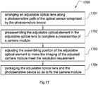
- the present invention provides a manufacturing method of camera module, including the following steps:
- the adjustable optical element is at least an optical lens, wherein in the step (B), at least one optical lens is preassembled in the adjustable optical lens as a preassembled optical lens, wherein by adjusting the assembling position of the preassembled optical lens, the central axis line of the adjustable optical lens and the central axis line of the optical sensor are adjusted to coincide or be within an allowable range of deviation.
- the adjustable optical element is an aperture member, wherein in the step (B), the aperture member is preassembled on the top of the adjustable optical lens, wherein by adjusting the assembling position of the aperture member, the central axis line of the adjustable optical lens and the central axis line of the optical sensor are made to be coincided or be within an allowable range of deviation.
- the adjustable optical element includes an aperture member and at least an optical lens
- the aperture member and the optical lens are preassembled in the adjustable optical lens, wherein by adjusting the assembling positions of the aperture member and the preassembled optical lens, the central axis line of the adjustable optical lens and the central axis line of the optical sensor are made to be coincided or be within an allowable range of deviation.
- a side wall of an optical structural member included by the adjustable optical lens has at least one adjustment channel therein to connect the internal space of the optical structural member to the external environment, wherein the preassembled lens in the internal space of the optical structural member corresponding to the adjustment channel is adaptable to adjust its spatial position inside the optical structural member through the adjustment channel.
- the adjustment channel in the step (D), by an adhesive dispensing process in the adjustment channel, the adjustment channel is sealed, and by conducting a heating process, the adhesive for preassembling the optical lens and for the above adhesive dispensing process is solidified, so that the adjusted lens is affixed, so as to further fix the whole camera module.
- the adjustment channel is sealed, and by conducting a heating process, the adhesive for preassembling the optical lens and aperture member and for the above adhesive dispensing process is solidified, the adjusted lens and the aperture member are fixed, so as to further fix the whole camera module.
- the aperture member has at least an adhesive injection channel thereon, wherein the adhesive injection channel is corresponding to the preassembled optical lens, wherein by injecting adhesive into the adhesive injection channel and conducting heating process to solidify the adhesive for preassembling and the adhesive for adhesive dispensing, the adjusted optical lens is affixed, so as to further fix the whole camera module.
- the aperture member has at least an adhesive injection channel thereon, wherein the adhesive injection channel is corresponding to the preassembled optical lens, wherein by injecting adhesive into the adhesive injection channel and conducting heating process to solidify the adhesive for preassembling and the adhesive for adhesive dispensing, the adjusted optical lens and the aperture member are fixed, so as to further fix the whole camera module.
- assembling position of the adjustable optical element is adjusted through adjusting at least any one direction of the horizontal direction, vertical direction, tilt direction, and peripheral direction of the adjustable optical element.
- the adjustable optical element is preassembled with adhesive
- the adhesive used for preassembling is a mixed adhesive of an UV adhesive and a thermosetting adhesive, which become semi-solidified after ultraviolet exposure to achieve the preassembling of the adjustable optical element in the step (B), wherein in step (D) after the heating process, the adhesive will be completely solidified, to fix the whole camera module.
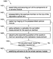
- the step (C) includes the following steps:
- the steps (C1) to (C3) need to be repeated until the imaging of the adjusted camera module meets the resolution requirement.
- the preassembled camera module is powered on and imaging of the camera module is captured, wherein the capturing of the imaging of the camera module is based on shooting MTF testing chart with the camera module, wherein the MTF value is applied to represent the imaging quality of the camera module.
- a greater MTF value indicates a higher imaging quality of the camera module.
- Every time when the imaging of the camera module is captured a MTF value corresponding to the imaging needs to be calculated.
- the MTF value is then checked to determine if it is greater than the standard. If the MTF value is greater than or equal to the standard, the capturing is completed; if the MTF value is lower than the standard, another capturing and adjusting will be required.
- environmental parameters for the shooting of the camera module including the parameter of light and distance between the MTF testing chart and the camera module, are strictly controlled, so as to ensure the accuracy and consistency of imaging capturing for implementing subsequent adjusting steps.
- a software applied to adjust the assembling position of the adjustable optical element is adaptable to be based on research of sensibility of optical design of optical lens.
- the method of applying software to calculate the calibration measurement of assembling position of the adjustable optical element includes: (1) measuring optical characteristics of the camera module, including MTF value, eccentricity of the optic axis, tilt angle of the optic axis, and field curvature, before calibration; and (2) calculating the calibration measurement required by the assembling position of the adjustable optical element based on the sensibility of the eccentricity of the optic axis, tilt angle of the optic axis, and field curvature of the assembling position of the adjustable optical element respectively.
- the step (A) by assembling the adjustable optical lens and the photosensitive device to achieve the fixed assembling for part of the optical elements comprised by the camera module, wherein the photosensitive device further comprises a filter, a lens mount, and a circuit board, wherein the filter is fixedly set on the lens mount, wherein the optical sensor is attached both on the top side of the circuit board and on the bottom side of the filter, wherein all elements of the adjustable optical lens besides of the adjustable optical element are fixed on the top side of the lens mount.
- the assembling tolerances of the above elements are controlled within an allowable range.
- the photosensitive device further comprises a filter and a circuit board, wherein the filter is fixedly set on an optical structural member comprised by the adjustable optical lens and is on the bottom side of the optical lens, wherein the optical sensor is attached both on the top side of the circuit board and on the bottom side of the filter, wherein the optical structural member is affixed correspondingly to the spatial distance between the optical sensor.
- the assembling tolerances of the above elements are controlled within an allowable range.
- the present invention provides an adjustable optical lens, including:
- the affixing channel and the adjustment channel are arranged at the same position on the optical structural member.
- Both the adjustment channel and the affixing channel correspond to the adjustable lens and communicate the internal space of the optical structural member to the external environment, such that the adjustable lens can communicate to the external environment of the optical structural member through the adjustment channel and the affixing channel, so as to be adjusted and affixed.
- the affixing channel and the adjustment channel are arranged at different positions on the optical structural member.
- Both the adjustment channel and the affixing channel correspond to the adjustable lens and communicate the internal space of the optical structural member to the external environment, such that the adjustable lens can communicate to the external environment of the optical structural member through the adjustment channel and the affixing channel, so as to be adjusted and affixed.
- the adjustable lens is the first piece of the optical lenses of the adjustable optical lens arranged on top of the optical structural member.
- the adjustable lens can be any one or more of the optical lenses arranged in the middle of the optical structural member.
- the adjustment channel and the affixing channel are both arranged on top of the optical structural member.
- the adjustment channel and the affixing channel are both arranged on side of the optical structural member.
- the adjustment channel is arranged on a side of the optical structural member and the affixing channel is arranged on top of the optical structural member.
- the adjustment channel is arranged on a top of the optical structural member and the affixing channel is arranged on side of the optical structural member.
- the assembling position of the adjustable lens can be adjusted through inserting an external adjustment device into the adjustment channel to contact the adjustable lens, wherein the assembling position of the adjustable lens is adaptable to be adjusted in at least one direction, such that the optical path of the adjustable optical lens can be calibrated.
- the external adjustment device has automation function, which is adaptable to record the adjusting method and calibration measurement of the adjustable lens or it is adaptable to input the adjusting method and calibration measurement of the adjustable lens into the external adjustment device.
- the adjusted adjustable lens can be affixed through injecting adhesive onto the edge of the adjustable lens with a glue dispensing device and then solidifying the adhesive.
- the adhesive is adaptable to be injected to a top surface of the adjustable lens, so as to affixed the adjustable lens through affixing the top surface of the adjustable lens with the inner wall of the optical structural member.
- the adhesive is adaptable to be injected to a side of the adjustable lens, so as to affixed the adjustable lens through affixing the side of the adjustable lens with the inner wall of the optical structural member.
- the adjustable lens has at least an adjustment groove arranged on the edge of the adjustable lens, wherein it is adaptable to insert an external adjustment device through the adjustment channel into the adjustment groove to adjust the assembling position of the adjustable lens.
- the present invention also provides a camera module, including:
- the affixing channel and the adjustment channel are arranged at the same position on the optical structural member.
- Both the adjustment channel and the affixing channel correspond to the adjustable lens and communicate the internal space of the optical structural member to the external environment, such that the adjustable lens can communicate to the external environment of the optical structural member through the adjustment channel and the affixing channel, so as to be adjusted and affixed.
- the affixing channel and the adjustment channel are arranged at different positions on the optical structural member.
- Both the adjustment channel and the affixing channel correspond to the adjustable lens and communicate the internal space of the optical structural member to the external environment, such that the adjustable lens can communicate to the external environment of the optical structural member through the adjustment channel and the affixing channel, so as to be adjusted and affixed.
- the adjustable lens is the first piece of the optical lenses of the adjustable optical lens arranged on top of the optical structural member.
- the adjustable lens can be any one or more of the optical lenses arranged in the middle of the optical structural member.
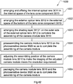
- the present invention also provides a calibration method of camera module, which includes the following steps:
- the step (A) it may either assemble the preassembled adjustable optical lens with a photosensitive device or assemble the optical lenses after the optical structural member is assembled on the photosensitive device.
- the step (B) comprises the following steps: (B1) powering on the preassembled camera module and capturing the imaging of the camera module;(B2) calculating the adjusting method and calibration measurement for the adjustable lens based on the imaging of the camera module; and (B3) adjusting the adjustable lens based on the calibration measurement.
- an external adjustment device is inserted into the adjustment channel to contact the adjustable lens and adjust the assembling position of the adjustable lens in at least one direction, wherein after adjustment, the central axis line of the adjustable optical lens and the central axis line of an optical sensor coincide or are within an allowable range of deviance.
- the external adjustment device has automation function, which is adaptable to record the adjusting method and calibration measurement of the adjustable lens or it is adaptable to input the adjusting method and calibration measurement of the adjustable lens into the external adjustment device to precisely adjust the adjustable lens.
- the external adjustment device adjusts the adjustable lens through machine holding or vacuum suction.
- the adjusted adjustable lens in the step (C), can be affixed through injecting adhesive onto the edge of the adjustable lens with a glue dispensing device and then solidifying the adhesive.
- adhesive is injected to a top surface of the adjustable lens, so as to affix the adjustable lens through affixing the top surface of the adjustable lens with the inner wall of the optical structural member.
- adhesive is injected to a side of the adjustable lens, so as to affix the adjustable lens through affixing the side of the adjustable lens with the inner wall of the optical structural member.
- the present invention also provides a calibration method of camera module, which includes the following steps:
- the step (d) comprises the following steps: (d1) powering on the preassembled camera module and capturing the imaging of the camera module;(d2) calculating the adjusting method and calibration measurement for the adjustable lens based on the imaging of the camera module; and (d3) adjusting the adjustable lens based on the calibration measurement, so as to calibrate the camera module.
- the adjustable lens is contacted by an external adjustment device from the light incident position on the top of the optical structural member, such that the assembling position of the adjustable lens can be adjusted in at least one direction.
- the external adjustment device adjusts the adjustable lens through machine holding or vacuum suction.
- the present invention in the step (e), adhesive is injected from the light incident position on the top of the optical structural member and the adjustable lens is affixed in the internal space of the optical structural member through solidifying the adhesive.
- the present invention also provides a camera module lens, including:
- the internal optical lenses are joined and assembled into a whole to be affixed in the lens cone component.
- the adjacent internal optical lenses are embedded or integrated with each other by means of spacer ring or adhesive.
- At least a piece of the internal optical lenses is preassembled in the lens cone component to serve as an adjustable lens, wherein the assembling position of the adjustable lens is adaptable to be adjusted correspondingly to the spatial position of the lens cone component in at least one direction.
- the lens cone component has at least an adjustment channel arranged along the peripheral direction of the outer side thereof.
- the adjustment channel(s) communicate the internal space of the lens cone component and the external environment and correspond to the adjustable lens(es) respectively, such that it is adaptable to adjust the optical path of the camera module lens by adjusting the assembling position of the adjustable lens through the adjustment channel.
- the adjustable lens is affixed on the inner wall of the lens cone component by adhesive injected through the adjustment channel by a glue dispensing device, which also seals the adjustment channel.
- the top of the lens cone component has at least an affixing channel corresponding to the edge of the adjustable lens to communicate the edge of the adjustable lens with the external environment, so as to make it suitable to affixed the adjustable lens by injecting adhesive through the affixing channel.
- the external optical lens is affixed on the bottom of the lens cone component, wherein the edge of the top surface of the external optical lens and the bottom surface of the lens cone component are connected.
- the external optical lens is preassembled on the bottom of the lens cone component to serve as an adjustable lens.
- the edge of the top surface of the external optical lens and the bottom surface of the lens cone component are connected.
- the assembling position of the external optical lens is adaptable to be adjusted in at least one direction correspondingly to the assembling position of the lens cone component.
- the outer side of each the external optical lens has a shading layer that completely covers the entire side of the external optical lens.
- the shading layer is formed on the outer side of each the external optical lens through painting black glue thereon.
- the present invention also provides a camera module, including:
- the external optical lens is affixed between the lens cone component and the lens mount, wherein the edge of the top surface and the edge of the bottom surface of the external optical lens are respectively affixedly connected with the bottom surface of the lens cone component and the top surface of the lens mount.
- the external optical lens serving as the adjustable lens is preassembled between the lens cone component and the lens mount.
- the edge of the top surface and the edge of the bottom surface of the external optical lens are respectively connected with the bottom surface of the lens cone component and the top surface of the lens mount in a movable manner.
- the assembling positions of the external optical lens and the lens cone component correspondingly to the assembling position of the optical sensor are both adaptable to be adjusted in at least one direction. After adjustment, the central axis line of the camera module lens and the central axis line of the optical sensor coincide or are within an allowable range of deviance.
- the external optical lens is preassembled between the lens cone component and the lens mount.
- the edge of the top surface of the external optical lens is affixedly connected with the bottom surface of the lens cone component, while the edge of the bottom surface of the external optical lens and the bottom surface of the lens cone component are preassembled in a movable manner, such that the assembling position of the camera module lens correspondingly to the assembling position of the optical sensor is adaptable to be adjusted in at least one direction.
- the central axis line of the camera module lens and the central axis line of the optical sensor coincide or are within an allowable range of deviance.
- the external optical lens is preassemble on the lens mount by a gluing after, wherein the adhesive used in the preassembling is a mixed adhesive of an UV adhesive and a thermosetting adhesive, which become semi-solidified after ultraviolet exposure to achieve the preassembling, wherein the adhesive will be completely solidified after adjustment, so as to affix the external optical lens.
- the adhesive used in the preassembling is a mixed adhesive of an UV adhesive and a thermosetting adhesive, which become semi-solidified after ultraviolet exposure to achieve the preassembling, wherein the adhesive will be completely solidified after adjustment, so as to affix the external optical lens.
- the present invention also provides a assembling method of an optical lens of a camera module, which includes the following steps:
- the method further comprises step (D): arranging a shading layer on the outer side of the external optical lens, wherein the arranging of the shading layer is adaptable to be conducted either before or after the assembling of the external optical lens.
- the present invention also provides a assembling method of camera module, which includes the following steps:
- the internal optical lenses are joined and assembled in a predesigned order into a whole, which is then affixed in the internal space of the lens cone component.
- the internal optical lenses are affixed in the internal space of the lens cone component in a predesigned order one after another;
- step (a) at least a piece of internal optical lenses serving as the adjustable lens is preassembled in the internal space of the lens cone component, wherein the assembling position of the adjustable lens is adaptable to be adjusted in at least one direction correspondingly to the internal space of the lens cone component.
- the lens cone component has at least an adjustment channel arranged thereon communicating the internal space of the lens cone component and the external environment and corresponding to the adjustable lens to be adaptable for an external adjustment device to contact the outer side of the adjustable lens through the adjustment channel, so as to adjust the assembling position of the adjustable lens, wherein after the adjustment, the central axis line of the camera module lens and the central axis line of the optical sensor coincide or are within an allowable range of deviance.
- the adjustable lens is affixed on the inner wall of the lens cone component by adhesive injected through the adjustment channel by a glue dispensing device, which also seals the adjustment channel.
- the top of the lens cone component has at least an affixing channel corresponding to the edge of the adjustable lens to communicate the edge of the adjustable lens with the external environment, so as to make it suitable to affixed the adjustable lens by injecting adhesive through the affixing channel.
- the external optical lens is affixed between the lens cone component and a lens mount.
- the external optical lens and the lens cone component are affixedly connected through applying adhesive on the edge of the top surface of the external optical lens and the bottom surface of the lens cone component.
- the external optical lens and the lens mount are affixedly connected through applying adhesive on the edge of the bottom surface of the external optical lens and the top surface of the lens mount.
- the external optical lens is preassembled between the lens cone component and a lens mount to serve as an adjustable lens.
- the external optical lens and the lens cone component are preassembled through applying adhesive between the edge of the top surface of the external optical lens and the bottom surface of the lens cone component.
- the external optical lens and the lens mount are preassembled through applying adhesive on the edge of the bottom surface of the external optical lens and the top surface of the lens mount.
- the assembling positions of the external optical lens and the lens cone component correspondingly to optical sensor are both adaptable to be adjusted in at least one direction.
- the external optical lens is preassembled between the lens cone component and a lens mount to serve as an adjustable lens.
- the external optical lens and the lens cone component are affixedly connected through applying adhesive between the edge of the top surface of the external optical lens and the bottom surface of the lens cone component.
- the external optical lens and the lens mount are preassembled through applying adhesive on the edge of the bottom surface of the external optical lens and the top surface of the lens mount.
- the assembling positions of the external optical lens and the lens cone component correspondingly to optical sensor are both adaptable to be adjusted in at least one direction.
- the external optical lens is preassembled between the lens cone component and a lens mount to serve as an adjustable lens.
- the external optical lens and the lens cone component are preassembled through applying adhesive between the edge of the top surface of the external optical lens and the bottom surface of the lens cone component.
- the external optical lens and the lens mount are affixedly connected through applying adhesive on the edge of the bottom surface of the external optical lens and the top surface of the lens mount.
- the assembling position of the lens cone component correspondingly to optical sensor is adaptable to be adjusted in at least one direction.
- the step (e) comprises the following steps: (e1) powering on the preassembled camera module and capturing the imaging of the camera module; (e2) calculating the adjusting method and calibration measurement for the adjustable lens based on the imaging of the camera module; and (e3) adjusting the adjustable lens based on the calibration measurement, so as to make imaging of the camera module meets a resolution requirement.
- the adjustable lens in the step (f), is affixed through glue dispensing, so as to complete the assembling of the camera module;
- the arranging of the shading layer is adaptable to be conducted either before or after the assembling of the external optical lens.
- the shading layer is formed on the outer side of each the external optical lens through painting black glue thereon, wherein the shading layer completely covers the entire side of the external optical lens.
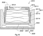
- an adjustable optical lens 1010 according to a preferred embodiment of the present invention is illustrated.
- the central axis line of the adjustable optical lens 1010 is able to be adjusted again after the adjustable optical lens 1010 has been produced, so that when the adjustable optical lens 1010 is subsequently applied to an imaging system, the central axis line of the adjustable optical lens 1010 can be adjusted based on specific parameters of the imaging system.
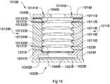
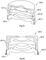
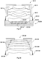
- the adjustable optical lens 1010 comprises an optical structural member 1013 and two or more lens 1011.
- Each lens 1011 is arranged in an internal space of the optical structural member 1013 along an axial direction of the optical structural member 1013, wherein position of at least one lens 1011 in the internal space of the optical structural member 1013 is arranged in an adjustable configuration.
- the central axis line of the adjustable optical lens 1010 is arranged to be adjustable based on the application needs of the imaging system after the adjustable optical lens 1010 is produced.
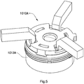
- the optical structural member 1013 of the adjustable optical lens 1010 has at least one adjustment channel 10131 to respectively communicate the internal space of the optical structural member 1013 with the external environment, wherein when the optical lenses 1011 are all overlappingly and spacedly arranged in the internal space of the optical structural member 1013 along the vertical direction of the optical structural member 1013, an outer wall of each lens 1011 is arranged on a position corresponding to the adjustment channels 10131. Therefore, the positions of the optical lenses 1011 in the internal space of the optical structural member 1013 can be adjusted later from the external environment of the optical structural member 1013 through the adjustment channels 10131, which is able to achieve the adjustment of the central axis line of the adjustable optical lens 1010.
- the adjustment channel 10131 is arranged on a side wall of the optical structural member 1013 at the position corresponding to the optical lens 1011 to be adjusted. More specifically, when the optical lens 1011 to be adjusted is arranged in the optical structural member, the edge of the optical lens 1011 will face the adjustment channel 10131 so as for a adjustment element to reach the edge of the optical lens 1011 through the adjustment channel and to engage with the edge of the optical lens 1011 to adjust the optical lens 1011.
- the adjustment channel 10131 may also be arranged at other position of the optical structural member 1013, such as the top wall of the optical structural member 1013, wherein the present invention shall not be limited here.
- position and quantity of the adjustment channel 10131 can be vary based on the need.
- the adjustment channels corresponding to the same optical lens 1011 can be arranged in positions based on the need.
- the two adjustment channels 10131 can be arranged in the same diameter, while if there are three adjustment channels, the three adjustment channels can be arranged in a axial symmetry manner to be spaced with one another in 120°, so as for symmetrically adjusting the optical lens 1011 to make the adjustment more accurate and easy.
- the present invention shall not be limited here.
- the adjustable optical lens 1010 uses an example that the theories of the adjustable optical lens 1010 can be described by adjusting the position of the outermost lens 1011 in the internal space structural member 1013.
- the adjustable optical lens 1010 comprises one the optical structural member 1013 and a plurality of the optical lenses 1011 overlappingly arranged in the internal space of the optical structural member 1013.
- the optical structural member 1013 has at least one the adjustment channel 10131, wherein the outermost optical lens 1011 is located at the position corresponding to the adjustment channel 10131 in the optical structural member 1013.
- the optical lens 1011 does not contact the inner wall of the optical structural member 1013, such that position of the optical lens 1011 in the optical structural member 1013 is adjustable.
- a gap is formed between the outer wall of the optical lens 1011 and the inner wall of the optical structural member 1013, wherein the size of the gap can be greater than or equal to 3 micrometers.
- An end of an adjustment element is applied to insert from outside of the optical structural member 1013 into the adjustment channel 10131 and is extended to the internal space of the optical structural member 1013, so as to push against the outer wall of the optical lens 1011, and then the position of the optical lens 1011 in the internal space of the optical structural member 1013 can be adjusted, and the central axis line of the adjustable optical lens 1010 can be adjusted.
- the position of lens 1011 and optical structural member 1010 are fixed again.
- the positions of lens 1011 and camera lens 1010 can be fixed by a gluing process or a welding process, so as to ensure the reliability of the adjustable optical lens 1010 while in use.
- the distance for the optical lens 1011 to be adjusted in the internal space of the optical structural member 1013 is equal to or smaller than the gap between the outer wall of the optical lens 1011 and the inner wall of the optical structural member 1013.
- FIGs. 1 and 2 of the drawings show that the optical lens 1011 in the internal space of the optical structural member 1013 is able to be adjusted by arranging the adjustment channels 10131 on the optical structural member 1013 of the adjustable optical lens 1010, those skilled in the art should understand that any other possible methods that can be used to adjust the relative position of the optical lens 1011 in the internal space of the optical structural member 1013 can be applied and shall be considered modified implementation according to the adjustable optical lens 1010 of the present invention.
- the present invention also provides a camera module that has the adjustable optical lens 1010, wherein the camera module also comprises an optical sensor 1021.
- the adjustable optical lens 1010 is arranged to the optical sensor 1021 that lights reflected from an object can enter an inside of the camera module of through the optical lens 1010 and be received by the optical sensor 1021 to proceed photoelectric conversion, so that images respective to the object can be generated by the camera module.
- a manufacturing method of the camera module is illustrated.
- the adjustable optical lens 1010 is arranged in the photosensitive path of the optical sensor 1021. Because a certain deviation may exist in the manufacturing method of the camera module, the central axis line of the adjustable optical lens 1010 cannot be accurately controlled. Therefore, after the adjustable optical lens 1010 is arranged in the photosensitive path of the optical sensor 1021, the central axis line of the adjustable optical lens 1010 and the central axis line of the optical sensor 1021 are coincided by adjusting the position of the optical lens 1011 in the internal space of the optical structural member 1013.
- the adjustable optical lens 1010 and the optical sensor 1021 are packaged to complete the manufacturing method of the camera module.
- the central axis line of the adjustable optical lens 1010 and the central axis line of the optical sensor 1021 in the present invention are coincided, wherein a deviation between the central axis line of the adjustable optical lens 1010 and the central axis line of the optical sensor 1021 are controlled within an acceptable range, so that the yield rate of the camera module can be increased and the image quality of the camera module is guaranteed.
- the central axis line of the adjustable optical lens 1010 can be adjusted not only by changing a horizontal position of the optical lens 1011 in the internal space of the optical structural member 1013, but also by changing a tilt position of the optical lens 1011 in the internal space of the optical structural member 1013. Furthermore, in another embodiment of the present invention, a vertical position of the optical lens 1011 in the internal space of the optical structural member 1013 can also be adjusted based on the application needs of the camera module. Therefore, a structure design of the camera module becomes more flexible.
- the present invention also comprises a manufacturing method 400 of a camera module, wherein the manufacturing method 400 comprises the following steps:
- the central axis line of the adjustable optical lens 1010 and the central axis line of the optical sensor 1021 are coincided by adjusting the position of the optical lens 1011 at the outermost of the adjustable optical lens 1010.
- position of the optical lens 1011 of the adjustable optical lens 1010 in the internal space of the optical structural member 1013 is able to be adjusted in at least one direction, for example, a horizontal direction.
- each of the direction of the horizontal direction, vertical direction, and tilt direction of the optical lens 1011 of the adjustable optical lens 1010 in the internal space of the optical structural member 1013 can be adjusted. Therefore, image qualities of the camera module generated from the adjustable optical lens 1010 can be guaranteed.
- at least one of the optical lenses 1011 in the internal space of the optical structural member 1013 can be adjusted to rotate, so as to fulfill the application needs for packaging different types of camera module.
- the step (402) after the position of the optical lens 1011 in the internal space of the optical structural member 1013 is adjusted, the adjusted lens 1011 and optical structural member 1013 are packaged. Therefore, the step for packaging the adjustable optical lens 1010 and the optical sensor 1021 is able to prevent deviation generated between the adjusted optical lenses 1011, so as to guarantee the image quality of the camera module.
- a side portion of the optical structural member 1013 has at least an adjustment channel 10131 formed on positions which is corresponding to at least one the optical lens 1011 arranged in the internal space of the optical structural member 1013, so that the position of the optical lens 1011 in the internal space of the optical structural member 1013 from the external environment of the optical structural member 1013 is able to be adjusted through the adjustment channel 10131.
- an adjustable optical lens 1010A according to a second preferred embodiment of the present invention is illustrated, wherein the adjustable optical lens 1010A comprises an optical structural member 1013A and at least two lens 1011A. At least one of the lenses 1011A is adjustably installed in the optical structural member 1013A. Contrasting to conventional optical lens, the optical structural member 1013A of the adjustable optical lens 1010A of the present invention is separately arranged from at least one of the optical lenses 1011A. Besides, the adjustable optical lens 1010A and an optical sensor 1021A such as a photosensitive chip are packaged to produce a camera module.
- the optical lens 1011A is installed in the optical structural member 1013A based on the corresponding relation between the central axis line of the adjustable optical lens 1010A and the central axis line of the optical sensor 1021A. Accordingly, image qualities of the camera module formed of the adjustable optical lens 1010A can be improved.
- each lens 1011A can be installed in the optical structural member 1013A based on the corresponding relation between the central axis line of the adjustable optical lens 1010A and the central axis line of the optical sensor 1021A, and then the adjustable optical lens 1010A and an optical sensor 1021A are packaged to produce the camera module.
- the optical lens 1011A at the outermost of the adjustable optical lens 1010A can be installed in the optical structural member 1013A based on the corresponding relation between the central axis line of the adjustable optical lens 1010A and the central axis line of the optical sensor 1021A, and then the adjustable optical lens 1010A and the optical sensor 1021A are packaged to produce the camera module.
- the optical lens 1011A is installed in the optical structural member 1013A, the optical lens 1011A and the optical structural member 1013A are solidified. Therefore, image qualities of the manufactured camera module can be improved.
- Figs. 6 and 7 illustrate manufacturing flow of the camera module according to the above preferred embodiment of the present invention, wherein the camera module can not only be a prime lens camera module, but also can be an auto-focus lens camera module.
- the difference between the prime lens camera module and the auto-focus lens camera module is that the adjustable optical lens 1010A of the prime lens camera module is directly packaged on a lens mount for connecting the adjustable optical lens 1010A and a photosensitive device 1020A, wherein the photosensitive device 1020A comprises at least one optical sensor 1021A.
- the photosensitive device 1020A may also comprise a circuit board attached by the optical sensor 1021A.
- the adjustable optical lens 1010A of the auto-focus lens camera module is installed with a driver, such as a voice coil motor, and then the driver is installed on the lens holder, so that when the auto-focus lens camera module is in use, the adjustable optical lens 1010A can be driven by the driver for moving along the photosensitive path of the optical sensor 1021A, which is defined as an offset movement of the optical sensor 1021A.
- a driver such as a voice coil motor
- the optical structural member 1013A can be installed along the photosensitive path of the optical sensor 1021A before that the optical lens 1011A is installed in the optical structural member 1013A. Also, after the position of the optical lens 12A in the internal space of the optical structural member 1013A is adjusted, the central axis line of the adjustable optical lens 10A and the central axis line of the optical sensor 1021A are coincided.
- the optical lens 1011A is arranged in the optical structural member 1013A, the central axis line of the adjustable optical lens 1010A and the central axis line of the optical sensor 1021A are coincided, and then the optical lens 1011 A and the optical structural member 1013A are affixed.
- the optical lens 1011A and the optical structural member 1013A are affixed by an adhesive dispensing process.
- FIG. 8 another manufacturing method 900 of a camera module according to the above preferred embodiment of the present invention is illustrated, wherein the manufacturing method 900 comprises the following steps:
- the optical structural member 1013A is arranged in the photosensitive path of the optical sensor 1021A. Also, in the step (902), the optical lenses are overlappingly and spacedly arranged in the internal space of the optical structural member 1013A along the axial direction of the optical structural member 1013A.
- the semi-finished article of the optical structural member 1013A arranged in the photosensitive path of the optical sensor 1021A, in the step (901), comprises an optical structural member 1013A and at least an optical lens 1011A which are preassembled in the internal space of the optical structural member 1013A, and the rest of the optical lenses 1011A are arranged in the internal of the optical structural member 1013A to form the adjustable optical lens 1010A, in the step (902).
- a camera module of an adjustable optical lens according to a third preferred embodiment of the present invention is illustrated.
- a camera module comprises an adjustable optical lens 10B and a photosensitive device 20B.
- the adjustable optical lens 1010B is installed in a photosensitive path of the photosensitive device 1020B that lights reflected from an object enter the inside of the photosensitive device 1020B from the optical lens 1010B to be photoelectric converted, so that the camera module can subsequently generate images respective to the object.
- the photosensitive device 1020B comprises a filter 1022B, a lens mount 1024B, an optical sensor 1021B, and a circuit board, wherein the filter 1022B is fixed at a first groove 10241B arranged on the upper part of the inner wall of the lens mount 1024B and on the top of a photosensitive path of the optical sensor 1021B.
- the optical sensor 1021B is fixed at a second groove 10242B arranged on the lower part of the inner wall of the lens mount 1024B.
- the optical sensor 1021B is attached on the top side of the circuit board 1023B.
- the circuit board 1023B is installed at the bottom part of the lens mount 1024B.
- the filter 1022B, the optical lens 22B, the optical sensor 1021B, and the circuit board 1023B have finished the assembling and fixing among one another and cannot be adjusted in successive calibration.
- Lights reflected from an object may enter the inside of the camera module from the adjustable optical lens 1010B and then be received by the optical sensor 1021B to proceed photoelectric conversion, so that the camera module can subsequently generate images respective to the object.
- the adjustable optical lens 1010B comprises an optical structural member 1013B and one or more lenses 1011B.
- the optical lenses 1011B are respectively installed in the optical structural member 1013B along an axial direction of the optical structural member 1013B.
- the optical structural member 1013B is connected to the top portion of the lens mount 1024B and the optical lenses 1011B are arranged along a photosensitive path of the optical sensor 1021B.
- At least one of the optical lenses 1011B is preassembled inside of the optical structural member 1013B.
- the optical lens 1011B preassembled inside of the optical structural member 1013B is the adjustable optical element in the present preferred embodiment, which means that it is adaptable to be adjusted in the spatial position inside of the optical structural member 1013B, wherein the optical lens formed thereof is called adjustable optical lens.
- five lenses 12 are comprised, which are respectively a first optical lens 10111B, a second optical lens 10112B, a third optical lens 10113B, a fourth optical lens 10114B and a fifth optical lens 10115B.
- the five lenses 12 are orderly overlappingly installed in the inside of the optical structural member 1013B along the photosensitive path of the optical sensor 1021B, wherein the third optical lens 10113B, the fourth optical lens 10114B and the fifth optical lens 10115B have already been preassembled in the optical structural member 1013B and been fixed.
- the first optical lens 10111B and the second optical lens 10112B are preassembled into the optical structural member 1013B as adjustable optical elements to be adjusted for calibration in the subsequent process, so as to increase imaging quality of the camera module.
- some optical lenses of the five optical lenses are all fixed optical lenses, while the other optical lenses are the adjustable optical element.
- Optical lenses that comprise adjustable optical element are called adjustable optical lens.
- an adhesive 1040B is applied to orderly preassemble the second optical lens 10112B and the first optical lens 10111B into the optical structural member 1013B.
- the adhesive 1040B will not be completely solidified. That is, the adhesive 1040B will be semi-solidified to conduct the preassembling of the first optical lens 10111B and the second optical lens 10112B, which not only prevents them from over moving, but also make successive adjusting easier.
- the adhesive 1040B applied a mixed adhesive of an UV adhesive and a thermosetting adhesive, which become semi-solidified after ultraviolet exposure to achieve the preassembling. After the heating process, the adhesive 1040B will be completely solidified, to fix the first optical lens 10111B and the second optical lens 10112B, so as to fix the whole camera module.
- the adjustable optical lens 1010B further comprises an aperture member 1014B.
- the aperture member 1014B is connected to the top of the optical structural member 1013B for introducing incident light beam and limiting the volume of the incident light beam.
- the aperture member 13 is fixedly installed on the top of the optical structural member 1013B, on top of the first optical lens 10111B, and in the photosensitive path of the optical sensor 1021B.
- the central axis line of the aperture member 1014B and the central axis line of the optical sensor 23B coincide or are kept within an allowable range of deviation, so as to guarantee imaging quality of the camera module.
- the present embodiment applies six adjustment channels 10131B, wherein three of the adjustment channels 10131B are arranged on the sidewall of the optical structural member 10131B along the preassembling position of the first optical lens 10111B and separately arranged from one another at 120 degrees.
- the other three adjustment channels 10131B are arranged on the sidewall of the optical structural member 10131B along the preassembling position of the second optical lens 10112B and separately arranged from one another at 120 degrees.
- an elongated element such as a needle can be inserted into the corresponding adjustment channel 10131B.
- the needle By controlling the needle to poke the first optical lens 10111B and the second optical lens 10112B, horizontal and vertical positions of the first optical lens 10111B and the second optical lens 10112B at the three spots of the corresponding adjustment channels 10131B can be changed, so as to respectively conduct adjustments of the first optical lens 10111B and the second optical lens 10112B in any directions, including horizontal positions, vertical positions, and tilt positions.
- the optical structural member 1013B can be implemented as a lens cone, wherein the inner wall of the optical structural member 1013B has five limit structures 10133B.
- the limit structures 10133B are spacedly and protrudedly formed by extending the inner wall of the optical structural member 1013B toward the direction of the cavity thereof, so as to respectively bear five of the optical lenses 1011B, that is the first limit structure 101331B, the second limit structure 101332B, the third limit structure 101333B, the fourth limit structure 101334B, and the fifth limit structure 101335B which respectively bear the first optical lens 10111B, the second optical lens 10112B, the third optical lens 10113B, the fourth optical lens 10114B, and the fifth optical lens 10115B.
- the optical structural member 1013B can also apply other ways to bear each of the optical lenses 1011B.
- the camera module can also comprise a driver and the optical structural member 1013B can be a component of the driver.
- the camera module can not only be a prime lens camera module, but be an auto-focus lens camera module.
- Fig. 11 is a flow diagram of a manufacturing method 1100 of the camera module of the present preferred embodiment, wherein the manufacturing method 1100 of the camera module includes the steps of:
- the filter 1022B, the lens mount 1024B, the optical sensor 1021B, and the circuit board 1023B are assembled and fixed to form the photosensitive device 1020B.
- the optical structural member 1013B is assembled and fixed on the lens mount 1024B.
- the third optical lens 10113B, the fourth optical lens 10114B, and the fifth optical lens 10115B are fixedly assembled at the corresponding limit structures 10133B of the optical structural member 1013B.
- assembling tolerances among each of the above elements should be controlled to the smallest to be kept within the allowable range of tolerance as long as possible, so as to avoid increases successive adjustment or failure of successive adjusting due to overly high assembling tolerance.
- the second optical lens 10112B and the first optical lens 10111B are orderly preassembled into the optical structural member 1013B.
- An adhesive 1040B is applied in the preassembling.
- the adhesive 1040B is then semi-solidified under ultraviolet exposure to complete the preassembling of the second optical lens 10112B and the first optical lens 10111B.
- the aperture member 1014B is fixedly assembled on the top of the optical structural member 1013B. At this point, the preassembling of the camera module is finished through the partial fixedly assembling, which makes the optical lens of the camera module become the adjustable optical lens 10D.
- the preassembled camera module is powered on and imaging of the camera module is captured. Then the calibration measurements for the assembling positions of the first optical lens 10111B and the second optical lens 10112B are respectively calculated based on the imaging of the camera module.
- Capturing of the imaging of the camera module is based on shooting a MTF (Modulation Transfer Function) testing chart with the camera module.
- the MTF value is applied to represent the imaging quality of the camera module. A greater MTF value indicates a higher imaging quality of the camera module. Every time when the imaging of the camera module is captured, a MTF value corresponding to the imaging needs to be calculated. The MTF value is then checked to determine if it is greater than the standard. If the MTF value is greater than or equal to the standard, the capturing is completed; if the MTF value is lower than the standard, another capturing and adjusting will be required.
- MTF Modulation Transfer Function
- the environmental parameters for the shooting of the camera module should be strictly controlled, so as to ensure the accuracy and consistency of imaging capturing for adjusting the assembling position of the adjustable optical element.
- a method of the software to calculate the calibration measurement of the assembling positions of the first optical lens 10111B and the second optical lens 10112B comprises the steps of: measuring optical characteristics of the camera module, including MTF value, eccentricity of the optic axis, tilt of the optic axis, and field curvature before adjusting based on the imaging of the camera module; and calculating the calibration measurements for the assembling positions of the first optical lens 10111B and the second optical lens 10112B based on the sensibility of the optical characteristics of the assembling positions of the first optical lens 10111B and the second optical lens 10112B.
- preassembling positions of the first optical lens 10111B and the second optical lens 10112B are respectively adjusted through corresponding adjustment channel 10131B, so as to ensure the first optical lens 10111B and the second optical lens 10112B in the optical structural member 1013B to properly turn. That is to say, the first optical lens 10111B and the second optical lens 10112B are properly adjusted in the horizontal position, vertical or axial position, and tilting position thereof, such that after adjusting, the central axis lines of the first optical lens 10111B and the second optical lens 10112B and the central axis line of the optical sensor 1021B are to coincide or within an allowable range of deviation. Meanwhile, imaging of the camera module after adjusting will meet the resolution requirement. If imaging of the camera module still fails to meet the resolution requirement after the adjustment, assembling positions of the first optical lens 10111B and the second optical lens 10112B should then further be adjusted.
- Each adjusting requires a capturing of the imaging of the camera module, which means to repeat the step (1103) to (1105) until the imaging of the camera module meets the requirement.
- the adjustable optical element is adjusted to the target position according to the calculated calibration measurement and the imaging of the camera module meets the resolution requirement, it can be considered that the central axis line of the adjustable optical lens 1010B and the central axis line of the optical sensor 1021B coincide or are within an allowable range of deviation, which means the adjusting satisfies the set requirement.
- step (1107) solidifying the adhesive 1040B through heating process fixes the first optical lens 10111B and the second optical lens 10112B in the optical structural member 1013B. Then the adjustment channel 10131B is sealed.
- the present embodiment preferably seals the adjustment channel 10131B by injecting adhesive or glue dispensing into the adjustment channel 10131B and then conducting heating process, or waiting to be heated with the adhesive 1040B to solidify the adhesive for sealing the adjustment channel 10131B and the adhesive 1040B at the same time, which seals the adjustment channel 111B and fixes the first optical lens 10111B and the second optical lens 10112B simultaneously, so as to package the adjustable optical lens 1010B and the photosensitive device 1020B and then to fix the whole camera module.
- the present invention may set at least one adhesive injection channel 10141B on the aperture member 1014B for injecting adhesive to further fixed the adjusted first optical lens 10111B.
- An implementation can have two adhesive injection channels 10141B that, after the first optical lens 10111B alone is adjusted or both the first optical lens 10111B and the second optical lens 10112B are adjusted, thermosetting adhesive is injected into the adhesive injection channels 10141B. After the heating process of the camera module, the first optical lens 10111B is further to be completely fixed. Meanwhile, the injected adhesive can also seal the injection channels 10141B after solidification.
- a camera module includes an adjustable optical lens 1010C and a photosensitive device 1020C.
- the adjustable optical lens comprises an optical structural member 1013C, three lenses 1011C (which are a first optical lens 10111C, a second optical lens122C and a third optical lens 10113C), and an aperture member 1014C, wherein the three lenses 1011C are installed inside the optical structural member 1013C along an axial direction of the optical structural member 1013C.
- the aperture member 1014C is preassembled on the top of the optical structural member 1013C, which is also on top of the first optical lens 10111C, while keeping a certain spacing therewith.
- the assembling position of the aperture member 1014C is able to be adjusted in at least one direction, such as X, Y, or Z direction, relative to the spatial position of the optical structural member 1013C.
- the aperture member 1014C is to be an adjustable optical element that an optical lens formed thereof becomes an adjustable optical lens.
- the photosensitive device 1020C comprises a filter 1022C, an optical sensor 1021C and a circuit board 1023C, wherein the optical structural member 1013C is also a lens mount of the photosensitive device 1020C.
- the filter 1022C is fixedly installed in the optical structural member 1013C and is under the bottom of the third optical lens 10113C.
- the optical sensor 1021C is fixedly installed in the optical structural member 1013C and attached on top of the circuit board 1023C under the bottom of the filter 1022C.
- the optical lenses 12C, the aperture member 1014C, and the filter 1022C are in a photosensitive path of the optical sensor 1021C, so lights reflected from an object may enter the inside of the camera module from the adjustable optical lens 1010C and then be received by the optical sensor 1021C to proceed photoelectric conversion, so that the camera module can subsequently generate images respective to the object.
- the inner wall of the optical structural member 1013C forms a first groove 10241C, a second groove 10242C and a third groove 223C, which are sequentially and spacedly set in the top, middle, and bottom of the optical structural member 1013C.
- the filter 1022C is installed in the second groove 10242C.
- the optical sensor 1021C is held in the third groove 223C and attached on the circuit board 1023C on top of the circuit board 1023C.
- the circuit board 1023C is installed in the bottom portion of the optical structural member 1013C.
- the first optical lens 10111C is fixedly installed at a first limit structure 101331C arranged on the inner wall of the optical structural member 1013C.
- the second optical lens 10112C is fixedly installed at a second limit structure 101332C arranged on the inner wall of the optical structural member 1013C.
- the third optical lens is installed at a third limit structure 101333C arranged on the inner wall of the optical structural member 1013C.
- the first limit structure 101331C, the second limit structure 101332C and the third limit structure 101333C are protrudedly formed by extending the inner wall of the optical structural member 1013C toward the direction of the cavity thereof, so as to respectively bear the first optical lens 10111C, the second optical lens 10112C and the third optical lens 10113C.
- a manufacturing method 1400 of the camera module of the present preferred embodiment comprises the steps of:
- part of the module components of the camera module are assembled and fixed. That is, the filter 1022C, the optical sensor 1021C and the circuit board 1023C are installed and fixed at the designated positions of the optical structural member 1013C. Also, the third optical lens 10113C, the second optical lens 10112C and the first optical lens 10111C are orderly installed and fixed at the designated positions in the optical structural member 1013C, so that the three lenses 12C are in a photosensitive path of the optical sensor 1021C, and that the central axis lines of the three lenses 1011C and the central axis line of the optical sensor 1021C coincide or are within an allowable range of deviation. Besides, assembling tolerances among each of the above components are strictly controlled to guarantee the imaging quality of the camera module and to reduce the workload of future adjusting.
- the aperture member 1014C is preassembled on the top of the optical structural member 1013C through the way of semi-solidifying the adhesive 1040C, so as to have the aperture member 1014C in the photosensitive path of the optical sensor 1021C and allow the aperture member 13 to be adjusted in at least one direction relative to the spatial position of the optical sensor 1021C or the optical structural member 1013C.
- the adhesive 1040C is preferably thermosetting adhesive that can be semi-solidified under ultraviolet exposure for preassembling.
- the preassembled camera module is powered on and imaging of the camera module is captured. Then the calibration measurement for the aperture member 1014C is calculated by the software based on the imaging of the camera module. Proper adjusting of the assembling position of the aperture member 1014C is conducted according to the calculated calibration measurement, so as to make the central axis line thereof and the central axis line of the optical sensor 1021C coincide or be within an allowable range of deviation, which is to also make the central axis line of the adjustable optical lens 1010C and the central axis line of the optical sensor 1021C coincide or be within an allowable range of deviation. At this point, the imaging of the camera module meets the resolution requirement. If imaging of the camera module still fails to meet the resolution requirement after the aperture member 1014C has been adjusted, further capturing of the imaging of the camera module and new adjusting of the aperture member 1014C are needed until it is adjusted to an eligible position and then fixed.
- the camera module will be heated, so as to completely solidify the adhesive 1040C that attaches the aperture member 1014C to the optical structural member 1013C, to then fix the whole camera module.
- the optical lens and aperture member may also directly be completely solidified after their positions are determined, which skips the semi-solidifying process.
- a camera module comprises an adjustable optical lens 1010D and a photosensitive device 1020D.
- the adjustable optical lens 1010D is installed in a photosensitive path of the photosensitive device 1020D that lights reflected from an object enter the inside of the photosensitive device 1020D from the optical lens 1010D to be photoelectric converted, so that the camera module can then generate images respective to the object.
- the photosensitive device 1020D comprises a filter 1022D, a lens mount 1024D, an optical sensor 1021D, and a circuit board, wherein the filter 1022D is fixed at a first groove 10241D arranged on an upper part of an inner wall of the lens mount 1024D and aligned in a top position of the photosensitive path of the optical sensor 1021D.
- the optical sensor 1021D is fixed at a second groove 10242D arranged on a lower part of the inner wall of the lens mount 1024D.
- the optical sensor 1021D is attached on the top side of the circuit board 1023D.
- the circuit board 1023D is fixed at the bottom part of the lens mount 1024D.
- the filter 1022D, the optical lens 22D, the optical sensor 1021D, and the circuit board 1023D have finished the assembling and fixing among one another and cannot be adjusted in successive calibration.
- Lights reflected from an object may enter the inside of the camera module from the adjustable optical lens 1010D and then be received by the optical sensor 1021D to proceed photoelectric conversion, so that the camera module can subsequently generate images respective to the object.
- the adjustable optical lens 1010D comprises an optical structural member 1013D and one or more lenses 1011D.
- the optical lenses 1011D are overlappedly and spacedly installed inside of the optical structural member 1013D along an axial direction of the optical structural member 1013D.
- the optical structural member 1013D is installed on a top portion of the lens mount 1024D and the optical lenses 1011D are aligned along the photosensitive path of the optical sensor 1021D.
- At least one of the optical lenses 1011D is preassembled inside of the optical structural member 1013D.
- the optical lens 12 preassembled inside of the optical structural member 1013D is an adjustable optical element, which means that it is adaptable to be adjust in at least one direction in the optical structural member 11D, wherein the optical lens formed thereof is called adjustable optical lens.
- the present preferred embodiment there are five lenses 12, which are a first optical lens 10111D, a second optical lens 10112D, a third optical lens 10113D, a fourth optical lens 10114D, and a fifth optical lens 10115D.
- Five lenses 12 are orderly, overlappingly and spacedly installed inside the optical structural member 1013D along the photosensitive path of the optical sensor 1021D, wherein the second optical lens 10112D, the third optical lens 10113D and the fourth optical lens 10114D have been preassembled in the optical structural member 1013D and been fixed that their positions are not adjustable.
- the first optical lens 10111D and the fifth optical lens 10115D are preassembled in the optical structural member 1013D as adjustable optical elements to be adjusted for calibration in the subsequent process, so as to increase imaging quality of the camera module.
- some optical lenses of the five optical lenses are all fixed optical lenses, while the other optical lenses are the adjustable optical element.
- Optical lenses that comprise adjustable optical element are called adjustable optical lens.
- an adhesive 1040D is applied to orderly preassemble the first optical lens 10111D and the fifth optical lens 10115D in the optical structural member 1013D.
- the adhesive 1040D will not be completely solidified. That is, the adhesive 1040 will be semi-solidified to conduct the preassembling of the first optical lens 10111D and the fifth optical lens 10115D, which not only prevents them from over moving, but also make successive adjusting easier.
- the adjustable optical lens 1010D further comprises an aperture member 1014D.
- the adhesive 1040D is applied to preassemble the aperture member 1014D on the top of the optical structural member 1013D for introducing incident light beam and limiting the volume of the incident light beam, wherein the assembling position of the aperture member 1014D is adaptable to be adjusted in at least one direction relative to the optical sensor 1021D, which is mainly adjusting in horizontal direction, but adjusting in vertical direction and tilt direction are also possible.
- the fifth optical lens 10115D is preassembled, and then the fourth optical lens 10114D, the third optical lens 10113D and the second optical lens 10112D are fixedly assembled.
- the first optical lens 10111D is preassembled in the optical structural member 1013D, and then the aperture member 1014D is preassembled on the top of the optical structural member 1013D.
- the aperture member 1014D is on top of the first optical lens 10111D and also positioned in the photosensitive path of the optical sensor 1021D.
- the first optical lens 10111D, the fifth optical lens 10115D and the aperture member 13D are adjustable optical elements that the assembling positions thereof are adaptable to be adjusted in at least one direction in the successive process of calibration or adjusting wherein the adjustable directions comprise horizontal direction, vertical direction, tilt direction, and peripheral direction.
- the central axis line of the adjustable optical lens and the central axis line of the optical sensor 1021D are made to coincide or be within an allowable range of deviation, so as to have the imaging of the camera module achieve the resolution requirement and to guarantee imaging quality of the camera module.
- the adhesive 1040D applied is a mixed adhesive of an UV adhesive and a thermosetting adhesive, which become semi-solidified after ultraviolet exposure to achieve the preassembling. After the heating process, the adhesive 1040D will be completely solidified to fix the whole camera module.
- the adjustment channels 10131D are respectively arranged in the sidewalls of the optical structural member 1013D corresponding to the first optical lens 10111D and the fifth optical lens 10115D, so as to adjust the spatial positions of the first optical lens 10111D and the fifth optical lens 10115D in the internal space of the optical structural member 1013D through the adjustment channels 10131D.
- the present embodiment applies six adjustment channels 10131D, wherein three of the adjustment channels 10131D are arranged on the sidewall of the optical structural member 10131D along the preassembling position of the first optical lens 10111D and separately arranged from one another at 120 degrees.
- the other three adjustment channels 10131D are arranged on the sidewall of the optical structural member 10131D along the preassembling position of the second optical lens 10112D and separately arranged from one another at 120 degrees.
- an elongated element such as a needle can be inserted into the corresponding adjustment channel 10131D.
- the needle By controlling the needle to poke the first optical lens 10111D and the fifth optical lens 10115D, horizontal and vertical positions of the first optical lens 10111D and the fifth optical lens 10115D at the three spots of the corresponding adjustment channels 10131D can be changed, so as to respectively conduct adjustment of the first optical lens 10111D and the fifth optical lens 10115D in directions including horizontal positions, vertical positions, and tilt positions.
- the aperture member 1014D is preassembled on the top of the adjustable optical lens 1010D, assembling position of the aperture member 13D can be adjusted through any practicable ways.
- the optical structural member 1013D can be implemented as a lens cone, wherein the inner wall of the optical structural member 1013D has five limit structures 10133D.
- the limit structures 10133D are spacedly and protrudedly formed by extending the inner wall of the optical structural member 1013D toward the direction of the cavity thereof, so as to respectively bear five of the optical lenses 1011D, that is the first limit structure 101331D, the second limit structure 101332D, the third limit structure 101333D, the fourth limit structure 101334D, and the fifth limit structure 101335D which respectively bear the first optical lens 10111D, the second optical lens 10112D, the third optical lens 10113D, the fourth optical lens 10114D, and the fifth optical lens 10115D.
- the optical structural member 1013D can also apply other ways to bear each of the optical lenses 1011D.
- the camera module can also comprise a driver and the optical structural member 1013D can be a component of the driver.
- the camera module can not only be a prime lens camera module, but be an auto-focus lens camera module.
- Fig. 17 is a flow diagram of a manufacturing method 1700 of the camera module of the present preferred embodiment, wherein the manufacturing method 1700 of the camera module includes the following steps:
- the filter 1022D, the lens mount 1024D, the optical sensor 1021D, and the circuit board 1023D are fixedly assembled to form the photosensitive device 1020D.
- the optical structural member 1013D is fixedly assembled on the lens mount 1024D.
- the second optical lens 10112D, the third optical lens 10113D and the fourth optical lens 10114D are fixedly assembled at the corresponding limit structures 10133D of the optical structural member 1013D.
- adjustable optical lens 1010D is set in the photosensitive path of the optical sensor 1021D to complete the fixing assembling of part of the components of the camera module.
- assembling tolerances among each of the above elements should be controlled to the smallest to be kept within the allowable range of tolerance as long as possible, so as to avoid increases of successive adjustment or failure of successive adjusting due to overly high assembling tolerance among each of the above elements
- the first optical lens 10111D and the fifth optical lens 10115D are preassembled in the optical structural member 1013D and the aperture member 1014D is preassembled on top of the optical structural member 1013D.
- An adhesive 1040D is used to conduct the preassembling of the first optical lens 10111D, the fifth optical lens 10115D and the aperture member 1014D.
- the adhesive 1040D is then semi-solidified by ultraviolet exposure to finish the preassembling of the first optical lens 10111D, the fifth optical lens 10115D and the aperture member 1014D.
- the first optical lens 10111D, the fifth optical lens 10115D and the aperture member 1014D in the present preferred embodiment are the adjustable optical elements to make the optical lens of the camera module that comprises the adjustable optical elements become the adjustable optical lens 1010D.
- the step (1703) comprises the steps of:
- step (1703) if the resolution requirement of the camera module fails to meet the request after the adjustable optical element was adjusted, the steps (17031) to (17033) need to be repeated until the resolution of the adjusted camera module meets the requirement.
- the calibration measurements for the assembling positions of the first optical lens 10111D, the fifth optical lens 10112D and the aperture member 1014D are respectively calculated based on the imaging of the camera module. Then according to each of the calibration measurements to respectively adjust the assembling positions of the first optical lens 10111D, the fifth optical lens 10115D and the aperture member 1014D.
- capturing of the imaging of the camera module is based on shooting a MTF (Modulation Transfer Function) testing chart with the camera module.
- the MTF value is applied to represent the imaging quality of the camera module. A greater MTF value indicates a higher imaging quality of the camera module. Every time when the imaging of the camera module is captured, a MTF value corresponding to the imaging needs to be calculated.
- the MTF value is then checked to determine if it is greater than the standard. If the MTF value is greater than or equal to the standard, the capturing is completed; if the MTF value is lower than the standard, another capturing and adjusting will be required.
- the environmental parameters for the shooting of the camera module should be strictly controlled, so as to ensure the accuracy and consistency of imaging capturing for adjusting the assembling position of the adjustable optical element.
- a method of the software to calculate the calibration measurement of the assembling positions of the first optical lens 121D, the fifth optical lens 125D and the aperture member 1014D comprises the steps of: measuring optical characteristics of the camera module, including MTF value, eccentricity of the optic axis, tilt of the optic axis, and field curvature before adjusting based on the imaging of the camera module; and calculating the calibration measurements for the assembling positions of the first optical lens 10111D, the fifth optical lens 10115D, and the aperture member 1014D based on the sensibility of the optical characteristics of the assembling positions of the first optical lens 10111D, the fifth optical lens 10115D and the aperture member 1014D.
- preassembling positions of the first optical lens 10111D, the fifth optical lens 10115D and the aperture member 1014D are respectively adjusted, so as to ensure the first optical lens 10111D and the fifth optical lens 10115D in the optical structural member 1013D to properly turn. That is to say, the first optical lens 10111D and the fifth optical lens 10115D are properly adjusted in the horizontal position, vertical or axial position, or tilting position thereof. Also, the horizontal position, vertical or axial position, or tilting position of the aperture member 1014D can also be properly adjusted accordingly.
- the central axis line of the adjustable optical lens 1010D and the central axis line of the optical sensor 1021D are to coincide or within an allowable range of deviation. Imaging of the camera module after adjusting also meets the resolution requirement. If imaging of the camera module still fails to meet the resolution requirement after the adjustment, assembling position of the adjustable optical element should then further be adjusted.
- the adjustable optical element is adjusted to the target position according to the calculated calibration measurement, it can be considered that the central axis line of the adjustable optical lens 1010D and the central axis line of the optical sensor 1021D coincide or are within an allowable range of deviation, which meets the target requirement that the imaging of the adjusted camera module meet the resolution requirement.
- step (1704) solidifying the adhesive 1040D through the heating process fixedly attaches the first optical lens 10111D, the fifth optical lens 10115D and the aperture member 1014D to the optical structural member 1013D. Then the adjustment channel 10131D is sealed.
- the present embodiment preferably conducts the sealing by injecting adhesive into the adjustment channel 10131D, which seals and further fixes the first optical lens 10111D and the second optical lens 10112D, so as to package the adjustable optical lens 1010D and the photosensitive device 1020D.
- the present invention may set at least one adhesive injection channel 10141D on the aperture member 1014D for injecting adhesive (e.g. thermosetting adhesive) to further fixed the adjusted first optical lens 10111D and fifth optical lens 10115D.
- adhesive e.g. thermosetting adhesive
- Another implementation can have two adhesive injection channels 10141D that, after the first optical lens 10111D and the fifth optical lens 10115D are adjusted, thermosetting adhesive is injected into the adhesive injection channels 10141D. After the heating process of the camera module, the first optical lens 10111D and the fifth optical lens 10115D are turned to be completely fixed. Meanwhile the adhesive injection channels 10141D can be sealed.
- a camera module comprises an adjustable optical lens 2010 and an photosensitive device 2020, wherein the photosensitive device 2020 comprises a optical sensor 2021.
- the adjustable optical lens 2010 is arranged along a photosensitive path of the optical sensor 2021 that lights reflected from an object can enter an inside of the camera module through the optical lens 2010 and be received by the optical sensor 2021 to proceed photoelectric conversion, so that images respective to the object can be subsequently captured by the camera module.
- the photosensitive device 2020 further comprises a filter 2022, a circuit board 2023, and a lens mount 2024.
- the filter 2022 is mounted in the lens mount 2024 and arranged above the optical sensor 2021.
- the optical sensor 2021 is attached on the circuit board 2023.
- the circuit board 2023 is mounted on the bottom of the lens mount 2024 so as to have the optical sensor 2021 located in the cavity defined in the internal of the lens mount 2024.
- the optical sensor 2021 keeps a distance from the lens mount 2024.
- the photosensitive device 2020 is manufactured with chip on board (COB) technology. Besides, according to the present invention, the photosensitive device 2020 can also be made with flip chip technology or other manufacture methods according to actual situation.
- COB chip on board
- the adjustable optical lens 2010 comprises at least an optical lens 2011 and an optical structural member 2013, wherein the optical lenses 2011 are arranged in the internal space of the optical structural member 2013 along the vertical direction of the optical structural member 2013, wherein at least one of the optical lenses 2011 is utilized as the adjustable lens that the assembling position thereof in the optical structural member 2013 is adaptable to be adjusted, such that the optical path of the adjustable optical lens 2010 can be adjusted. Therefore, the central axis line of the adjustable optical lens 2010 and the central axis line of the optical sensor 2021 can coincide or be within an allowable range of deviance after the adjustment, such that the imaging quality of the camera module can be ensured.
- the optical structural member 2013 can be a regular lens cone component or an integral module of lens cone component and lens mount, wherein the camera module can be a product with auto-focus device or an integral structure of a lens cone component with an auto-focus carrier.
- optical lenses 2011, which are respectively a first optical lens 20111, a second optical lens 20112, a third optical lens 20113, and a fourth optical lens 20114.
- the four optical lenses 2011 are orderly overlappingly arranged in the internal space of the optical structural member 2013, wherein the first optical lens 20111 is arranged on the top of the optical structural member 2013 and selected to be the adjustable lens.
- the adjustable lens (which means the first optical lens 20111 in the present embodiment) is preassembled in the optical structural member 2013 with the assembling position adaptable to be adjusted in at least one direction, such as one or more directions of the horizontal direction, vertical direction, tilt direction, and peripheral direction.
- the optical structural member 2013 has at least an adjustment channel 20131 arranged on the top thereof, which communicates the internal space of the optical structural member 2013 with external environment and corresponds to the adjustable optical lens 2011, so as to allow the adjustable lens be purposefully adjusted from the outside of the optical structural member 2013.
- an external adjustment device 2030 can be utilized to insert into the adjustment channels 20131. Because there is a gap left between the side of the adjustable lens and the interior of the optical structural member 2013, the external adjustment device 2030 can adjust the assembling position of the adjustable lens through contacting the side of the adjustable lens.
- the external adjustment device 2030 can be embodied as a probe according to the present preferred embodiment. The probe is then inserted into the adjustment channel 20131 to contact the side of the first optical lens 20111 and to be controlled to move the first optical lens 20111 and adjust the assembling position thereof.
- the probe may also be embodied to have electronic components and automation functions to automatically record the adjusting method and calibration measurement of the adjustable lens, so as to quantitatively determine if the adjustment is accurate or to precisely adjust the adjustable lens by inputting the adjusting method and calibration measurement of the adjustable lens into the probe, such that the adjustment.
- the adjusting method and calibration measurement of the adjustable lens are calculated with software based on the imaging of the camera module captured when powering on the preassembled camera module.
- the adjusting method and calibration measurement help the adjustable lens to be purposefully adjusted.
- the camera module can meet the expected requirement after at least one adjustment. Namely, the calibration becomes faster, which saves time for the adjustment and increases the efficiency and yield rate of the production.
- the adjustable lens After the adjustable lens is adjusted, it then has to be affixed so as to complete the calibration and assembling of the camera module.
- it can utilize an external affixing device to affix the adjustable lens.
- a glue dispensing device is utilized in the preferred embodiment to affix the first optical lens 20111 through glue dispensing.
- the glue dispensing device injects the adhesive 2040 into the adjustment channel 20131 and the adhesive is solidified so as to affixed the first optical lens 20111, wherein the adhesive 2040 can selectively be a thermosetting adhesive.
- the adhesive 2040 can be injected to a side of the first optical lens 20111, which means the adhesive 2040 is injected between the side of the first optical lens 20111 and the corresponding inner wall of the optical structural member 2013, so as to affix the first optical lens 20111 through affixing the side of the first optical lens 20111 with the inner wall of the optical structural member 2013.
- the adhesive 2040 may also be injected onto the top surface of the adjustable lens when the side of the adjustable lens is extended to the inner wall of the optical structural member 2013, such that the adjustable lens can be affixed through affixing the top surface of the adjustable lens on the inner wall of the optical structural member 2013.
- an adjustable optical lens 2010A according to an alternative mode of the above mentioned adjustable optical lens 2010 is illustrated in Fig. 20 .
- the adjustable optical lens 2010A comprises at least an optical lens 2011A and an optical structural member 2013A.
- the four optical lenses 2011A are respectively a first optical lens 20111A, a second optical lens 20112A, a third optical lens 20113A, and a fourth optical lens 20114A, which are respectively orderly and overlappingly arranged in the internal space of the optical structural member 2013 along the vertical direction of the optical structural member 2013A.
- the first optical lens 20111A (as the adjustable lens) being preassembled can be adjusted through at least an adjustment channel 20131A arranged on the top of the optical structural member 2013.
- the external adjustment device 2030 can be utilized to contact the top surface of the first optical lens 20111A to adjust the first optical lens 20111A as well. After the adjustment, the adjustment channel 20131A will also serve as affixing channel.
- the adjustment channel 20131A will also be utilized for adhesive 2040A injection to affix the first optical lens 20111A.
- the adhesive 2040A will be injected onto the top surface of the first optical lens 20111A and in the adjustment channel 20131A, so as to affixedly connected the top surface of the first optical lens 20111A and the inner wall of the optical structural member 2013A through the adhesive 2040A. It is suitable to fill the adhesive 2040A in the adjustment channel 20131 A in the injection process of the adhesive 2040A, such that the adjustment channel 20131A can also be sealed when the adjustable lens is affixed, which helps to prevent dust from entering, reduce on the working procedure, save time, and increase efficiency.
- a seventh embodiment of the camera module provided by the present invention will be illustrated.
- a camera module comprises an adjustable optical lens 2010B and a photosensitive device 2020, wherein the adjustable optical lens 2010B is arranged and affixed on the top of the photosensitive device 2020 based on the imaging need and the optical path of the camera module, wherein the photosensitive device 2020 is embodied the same as the above mentioned preferred embodiment, which will not be repeatedly described.
- the adjustable optical lens 2010B comprises at least an optical lens 2011B and an optical structural member 2013B.
- the optical lens 2011B comprises a first optical lens 20111B, a second optical lens 20112B, a third optical lens 20113B, and a fourth optical lens 20114B.
- the four optical lenses 2011B are arranged in the internal space of the optical structural member 2013B sequentially along the vertical direction of the optical structural member 2013B and along the photosensitive path of the optical sensor 2021.
- the first optical lens 20111B is arranged and preassembled on the top of the optical structural member 2013B to serve as the adjustable lens in the present preferred embodiment and its assembling position is adaptable to be adjusted in at least one direction.
- the optical structural member 2013B comprises at least an adjustment channel 20131B arranged on a side thereof.
- the adjustment channel 20131B is corresponding to the adjustable lens and communicating the internal space of the optical structural member 2013B to the external environment, so as for adjusting the adjustable lens.
- an external adjustment device 2030B can be utilized to insert into the adjustment channels 20131B. Because the edge of the first optical lens 20111B directly communicates to the outside through the adjustment channels 20131B, the external adjustment device can be utilized to adjust the assembling position of the first optical lens 20111B through contacting the edge of the first optical lens 20111B.
- the optical structural member 2013B has three of the affixing channels 122B arranged along a peripheral direction on the top thereof communicating the internal space of the optical structural member 2013B with the external environment, such that the adjustable lens can be affixed by injecting adhesive through the adjustment channels 20131B to have the adhesive contact the adjustable lens and the optical structural member 2013B.
- the adjustable lens is affixed on the optical structural member 2013B by injecting adhesive 2040B on the surface of the adjustable lens and solidifying it.
- the affixing channels 122B are separated from one another at 120 degrees and spaced with the adjustment channels 20131B, such that the adjustable lens can be affixed from multiple places, so as to ensure the reliability of affixing and functioning of the camera module.
- a camera module comprises an adjustable optical lens 2010C and a photosensitive device 2020, wherein the photosensitive device 2020 is embodied the same as the above mentioned preferred embodiment, which will not be repeatedly described.
- the adjustable optical lens 2010C comprises at least an optical lens 2011C and an optical structural member 2013C.
- the optical lens 2011C comprises a first optical lens 20111C, a second optical lens 20112C, a third optical lens 20113C, and a fourth optical lens 20114C.
- the four optical lenses 2011C are arranged in the internal space of the optical structural member 2013C sequentially along the vertical direction of the optical structural member 2013C and along the photosensitive path of the optical sensor 2021.
- the first optical lens 20111C is arranged and preassembled on the top of the optical structural member 2013C to serve as the adjustable lens in the present preferred embodiment and its assembling position is adaptable to be adjusted in at least one direction.
- the optical structural member 2013C comprises at least an adjustment channel 20131C arranged on a side thereof.
- the adjustment channel 20131C is corresponding to the adjustable lens and communicating the internal space of the optical structural member 2013C to the external environment, so as for adjusting the adjustable lens.
- an external adjustment device 2030C can be utilized to insert into the adjustment channels 20131C. Because the side of the first optical lens 20111C directly communicates to the outside through the adjustment channels 20131C, the external adjustment device 2030C can be utilized to adjust the assembling position of the first optical lens 20111C through contacting the side of the first optical lens 20111C.
- the part of the optical structural member 2013C that has the adjustment channel 20131C arranged thereon is taller than the lens mount 2024. That is to say, the adjustment channel 20131C on the side is arranged on a part of the optical structural member 2013C that protrudes from the lens mount 2024, which helps the adjustment of the adjustable lens from the outside of the optical structural member 2013C and avoids the lens mount 2024 from blocking the adjustment.
- adhesive is injected into the adjustment channel 20131C through a glue dispensing device, which has the adhesive contacts the first optical lens 20111C to affix the first optical lens 20111C on the optical structural member 2013C.
- more adhesive can be injected so as to affix the first optical lens 20111C and seal the adjustment channel 20131C at the same time.
- Figure 24 is an alternative mode of the above eighth preferred embodiment.
- the first optical lens 20111C is affixed through an affixing channel 122C arranged on the top of the optical structural member 2013C, wherein adhesive 2040C is injected through the affixing channel 122C.
- the top surface of the first optical lens 20111C is connected with external environment of the optical structural member 2013C, so as for injecting the adhesive 2040C into the affixing channel 122C.
- the first optical lens 20111C can be affixed when the adhesive is solidified on the surface of the first optical lens 20111C. Meanwhile, the solidified adhesive can seal the affixing channel 122C.
- the first optical lens 20111C can be affixed both through the adjustment channel 20131C and the affixing channel 122C.
- FIG. 25 is another alternative mode of the above eighth preferred embodiment.
- a camera module comprises an adjustable optical lens 2010D and a photosensitive device 2020, wherein the photosensitive device 2020 is embodied the same as the above mentioned preferred embodiment, which will not be repeatedly described.
- the adjustable optical lens 2010D is arranged in the photosensitive path of the photosensitive device 2020.
- the adjustable optical lens 2010D comprises at least an optical lens 2011D and an optical structural member 2013D.
- the optical lenses are arranged in the internal space of the optical structural member 2013D along the vertical direction of the optical structural member 2013D.
- there are four optical lenses 2011D which are respectively a first optical lens 20111D, a second optical lens 20112D, a third optical lens 20113D, and a fourth optical lens 20114D, wherein the first optical lens 20111D and the fourth optical lens 20114D are affixed in the optical structural member 2013D, while the second optical lens 20112D and the third optical lens 20113D are preassembled in the optical structural member 2013D to serve as adjustable lenses being arranging in the middle of the optical structural member 2013D, which assembling positions are suitable to be adjusted in at least one direction.
- the middle mentioned here means place other than the positions where the first optical lens 20111D and the fourth optical lens 20114D are arranged, which includes any position besides the top and bottom of the optical structural member 2013D.
- At least one adjustment channel 20131D each is arranged at the positions on the optical structural member 2013D respectively corresponding to the second optical lens 20112D and the third optical lens 20113D.
- the adjustment channels 20131D communicate the internal space of the optical structural member 2013D with external environment, so as for an external adjustment device 2030D to be inserted into the adjustment channels 20131D to respectively contact the edges of the second optical lens 20112D and the third optical lens 20113D to respectively adjust the assembling positions of the second optical lens 20112D and the third optical lens 20113D.
- the external adjustment device 2030D can be embodied as a probe with electronic components and automation function to automatically record the adjusting method and calibration measurement of the adjustable lens, so as to quantitatively determine if the adjustment of the adjustable lens is accurate or to precisely adjust the adjustable lens by inputting the adjusting method and calibration measurement of the adjustable lens on the external adjustment device 2030D, such that the adjustment can be more efficient.
- the adjustment channels 20131D may optionally have a plurality of the adjustment channels 20131D arranged along the outer side of the optical structural member 2013D.
- the adjustment channels 20131D surround around are corresponding to the corresponded adjustable lenses so as for adjusting the adjustable lenses from various directions to ensure the accuracy of the adjustment.
- it may have three of the adjustment channels 20131D arranged along the peripheral direction of the second optical lens 20112D and another three of the adjustment channels 20131D arranged along the peripheral direction of the third optical lens 20113D.
- the second optical lens 20112D and the third optical lens 20113D are adjusted, they are affixed through the adjustment channel 20131D.
- a glue dispensing device is utilized to dispense glue through the adjustment channels 20131D, so as to have the adhesive contact the edge of the second optical lens 20112D and the edge of the third optical lens 20113D, such that the second optical lens 20112D and the third optical lens 20113D can be respectively affixed on the inner wall of the optical structural member 2013D.
- the adhesive can also seal the adjustment channel 12D.
- the adhesive is preferably a thermosetting adhesive, so as to affix the second optical lens 20112D and the third optical lens 20113D and seal the adjustment channel 12D after a heating process.
- the adjustable lens if it is preassembled through semi-solidifying the adhesive, it will have to completely solidify the adhesive used in the preassembling in the subsequent affixing process. After the solidification, the adjustable lens will be affixed. Then it may further seal the adjustment channel 20131D through external glue dispensing or further affix the adjustable lens through another glue dispensing so as to guarantee the reliability of the affixing.
- the position for adjusting the adjustable lens and the position for affixing the adjustable lens may be the same position or different positions.
- it may have a plurality of the affixing channels arranged on the outer side of the optical structural member 2013D corresponding to the adjustable lens, wherein the affixing channels and the adjustment channels 20131E are spacedly arranged on the side of the optical structural member, such that the adjustable lens can both be adjusted and affixed from various directions.
- the adjustment channels 20131D arranged on part of the optical structural member 2013D, while the affixing channels arranged on the other part that the adjustment channels 20131D and the affixing channels are not spacedly arranged.
- a camera module comprises a adjustable optical lens 2010E and a photosensitive device 2020, wherein the photosensitive device 2020 is embodied the same to the above mentioned preferred embodiment, which will not be repeatedly described.
- the adjustable optical lens 2010E is arranged in the photosensitive path of the photosensitive device 2020 so as for shooting and imaging.
- the adjustable optical lens 2010E comprises at least one optical lens 2011E and an optical structural member 2013E, wherein each the optical lenses 2011E is set and affixed in the internal space of the optical structural member 2013E along the vertical direction of the optical structural member 2013E in the photosensitive path of the optical sensor 2021.
- the optical lenses 2011E there are four of the optical lenses 2011E, which are respectively a first optical lens 20111E, a second optical lens 20112E, a third optical lens 20113E, and a fourth optical lens 20114E, respectively arranged in the internal space of the optical structural member 2013E sequentially from top to bottom. That is, the first optical lens 20111E is arranged and preassembled in the top of the optical structural member 2013E.
- the assembling position of the first optical lens 20111E, as the adjustable lens of present preferred embodiment, is adaptable to be adjusted in at least one direction, so as for adjusting the optical path of the adjustable optical lens 2010E.
- the central axis line of the adjustable optical lens 2010E and the central axis line of the optical sensor 2021 coincide or are within an allowable range of deviance.
- the optical structural member 2013E has at least an adjustment channel 20131E arranged on the top thereof. According to the present embodiment, there are two adjustment channels 20131E communicating the internal space of the optical structural member 2013E with external environment, such that the surface of the first optical lens 20111E can communicate with the outside through adjustment channel 20131E and the assembling position thereof can therefore be adjusted.
- the first optical lens 20111E has at least two adjustment grooves 201111E arranged on the top surface thereof.
- the top opening of the adjustment grooves 201111E are respectively corresponding to the adjustment channels 20131E to be communicated with the external environment of the optical structural member 2013E through the adjustment channels 20131E.
- the adjustment grooves 201111E are preferably arranged at the positions near by the edge of the first optical lens 20111E, such that they will not affect the light path of the first optical lens 20111E, which ensures the imaging of the camera module.
- an external adjustment device 2030E is inserted into the adjustment channel 20131E to contact the first optical lens 20111E.
- the external adjustment device 2030E is inserted into the adjustment groove 201111E to grab the first optical lens 20111E through the adjustment groove 201111E and to adjust at least one of the horizontal position, vertical position, tilt position, and peripheral position of the first optical lens 20111E, such that the optical path of the adjustable optical lens 2010E can be adjusted to make the camera module meet the resolution requirement.
- the affixing position and the adjustment position are the same position, which are both at the adjustment channel 20131E.
- adhesive can be injected into the adjustment channel 20131E through a glue dispensing device.
- the adhesive in a liquid state or semi-solid state can flow onto the side or top surface of the first optical lens 20111E through the adjustment channel 20131E.
- the first optical lens 20111E can be affixed in the optical structural member 2013E after the adhesive is solidified.
- more adhesive can be injected so as to affix the first optical lens 20111E and seal the adjustment channel 20131E at the same time.
- Extra affixing channel may also be arranged for affixing the adjustable lens, wherein the position of the affixing channel may also be different from the position of the adjustment channel 20131E.
- a calibration method of the camera module according to the above four preferred embodiments of the present invention is illustrated, wherein the calibration method 1400 of the camera module includes the following steps:
- the step (1401) it may arrange at least one or more optical lens to be the adjustable lens, wherein the adjustable lens will not be affixed so as to be adjusted in the subsequent process.
- the adjustable lens is adjusted by utilizing external adjustment device through the adjustment channel of the optical structural member, wherein the adjustment channel may be arranged on the top or side of the optical structural member, which may refer to the above four preferred embodiments and the alternative modes thereof for specific information.
- the adjustable lens may be affixed through the affixing channel arranged on the optical structural member or the adjustment channel.
- the positions for affixing and adjusting the adjustable lens can be the same or different.
- the adhesive for affixing may function through contacting the side or top surface of the adjustable lens, which embodiments may refer to the above four preferred embodiments and the alternative modes thereof for specific information.
- a camera module comprises a adjustable optical lens 2010F and a photosensitive device 2020, wherein the photosensitive device 2020 is embodied the same to the above mentioned preferred embodiment, which will not be repeatedly described.
- the adjustable optical lens 2010F is arranged in the photosensitive path of the photosensitive device 2020 so as for shooting and imaging.
- the adjustable optical lens 2010F comprises at least one optical lens 2011F and an optical structural member 2013F, wherein each the optical lenses 2011F is set and affixed in the internal space of the optical structural member 2013F along the vertical direction of the optical structural member 2013F in the photosensitive path of the optical sensor 2021.
- the optical lenses 2011F there are four of the optical lenses 2011F, which are respectively a first optical lens 20111F, a second optical lens 20112F, a third optical lens 20113F, and a fourth optical lens 20114F, respectively arranged in the internal space of the optical structural member 2013F sequentially from top to bottom. That is, the first optical lens 20111F is arranged and preassembled in the top of the optical structural member 2013F.
- the assembling position of the first optical lens 20111F, as the adjustable lens of present preferred embodiment, is adaptable to be adjusted in at least one direction, so as for adjusting the optical path of the adjustable optical lens 2010F.
- the central axis line of the adjustable optical lens 2010F and the central axis line of the optical sensor 2021 coincide or are within an allowable range of deviance.
- the assembling of the adjustable optical lens 2010F will be completed when the first optical lens 20111F is affixed.
- a calibration method 1500 of the camera module comprises the following steps:
- the second optical lens 20112F, the third optical lenses 20113F, and the fourth optical lens 20114F can either be assembled in the optical structural member 2013F one by one or be integrated into a whole to be assembled in the optical structural member 2013F;
- the first optical lens 20111F is arranged in the internal space on the top of the optical structural member 2013F, positioned above the second optical lens 20112F, and preassembled as an adjustable lens, such that the assembling position thereof can be adjusted in the subsequent process.
- the adjustment of the adjustable lens is adaptable to be conducted from the top of the optical structural member 2013F, which does not require an adjustment channel that is particularly arranged. Hence, the working procedure becomes simpler.
- the adjustable lens can be directly contacted and adjusted via the position of the light incident channel 2015F on the top of the optical structural member 2013F. It is adaptable to utilize a device to enter from the top of the optical structural member 2013F to contact the adjustable lens during the adjustment. Then the adjustable lens can be adjusted by means of tool clamping or vacuum suction.
- the adhesive 2040F is injected into the light incident channel 2015F on the top of the optical structural member 2013F after the adjustment.
- the first optical lens 20111F will then be affixed after the adhesive 2040F is solidified. It does not require having an affixing channel particularly arranged, such that the structure can become simpler.
- the adjustable lens can be affixed on the inner wall of the optical structural member 2013F through dispensing adhesive on the edge of the adjustable lens and solidifying the adhesive.
- the adjustable lens can directly be preassembled in the optical structural member 2013F through being placed on a loading portion arranged in the optical structural member 2013F or through the adhesive being semi-solidified, which can prevent the adjustable lens from offset much and allow it to be adjusted in the subsequent process, such that the adjustment extent can be reduced, the adjustment frequency can be decreased, and the calibration efficiency can be increased.
- a camera module lens 3010 comprises at least one internal optical lenses 3011, at least an external optical lens 3012, and a lens cone component 3013.
- the internal optical lenses 3011 are arranged in an interior of the lens cone component 3013 along the vertical direction of the lens cone component 3013.
- the external optical lenses 3012 are arranging in the exterior of the lens cone component 3013, such as the external space of the top or bottom of the lens cone component 3013, along the vertical direction of the lens cone component.
- the internal optical lens 3012 and the internal optical lens 3011 are arranged in the same optical path of the camera module lens 3010, but the external optical lens 3012 is not contained in the interior of the lens cone component 3013.
- the preferred embodiment there are three internal optical lenses 3011 embedded and integrated with one another to be then affixed in an accommodating cavity 30131 of the lens cone component 3013, wherein adjacent internal optical lenses 3011 are connected with each other through spacer ring. It may also have the edge of the internal optical lenses 3011 be processed, such as painted with glue, so as to orderly bind and integrate the internal optical lenses 3011 through the painted glue without using structural elements like spacer ring or the like.
- a lens unit is formed by assembling the internal optical lenses 3011. Then the internal optical lenses 3011 are treated as a whole to be installed in the lens cone component 3013 and affixed.
- the external optical lens 3012 there is only one piece of the external optical lens 3012, wherein the external optical lens 3012 is installed on the bottom of the lens cone component 3013, wherein the edge of the external optical lens 3012 and the bottom of the lens cone component 3013 are connected.
- adhesive is applied on the edge of the top surface of the external optical lens 3012 and the bottom surface of the lens cone component 3013 so as to affixedly connect them and have the external optical lens 3012 correspond to the internal optical lenses 3011 and be in the optical path of the camera module lens 3010 together.
- the lens cone component 3013 is a conventional black lens barrel, it can both block external light from entering the internal of the camera module lens 3010 from positions besides light incident channel and avoid light entered via the light incident channel from leaking from the internal of the camera module lens 3010.
- the external optical lens 3012 is not arranged in the lens cone component 3013. Therefore, the present invention further provides a shading layer 30121 arranged on the outer side of the external optical lens 3012.
- the shading layer 30121 has to completely cover the entire side of the external optical lens 3012 so as to avoid light leakage of the camera module lens 3010 and prevent external stray light from entering the camera module lens 3010, such that the imaging quality of the camera module lens 3010 can be ensured.
- the camera module lens 3010 there may not be the shading layer 30121 arranged on the outer side of the external optical lens 3012.
- the camera module lens 3010 comprises the external optical lens 3012 without shading layer. Nonetheless, because the shading layer 30121 may still be arranged in the subsequent process, the shading layer 30121 is not necessary for the camera module lens 3010.
- the shading layer 30121 is arranged on the external optical lens 3012 assembled in the camera module. It may also arrange the shading layer 30121 on the outer side of the external optical lens 3012 of the camera module lens 3010 during the assembling of the camera module and have the camera module lens 3010 with the shading layer 30121 arranged be assembled with the photosensitive device to make the camera module.
- the camera module lens 3010 may or may not include the shading layer 30121.
- the options of the arrangement moment of the shading layer 30121 may include the following three: (1) arranging the shading layer 30121 on the outer side of the external optical lens 3012 beforehand and assembling the external optical lens 3012 on the camera module lens 3010; (2) arranging the shading layer 30121 after the external optical lens 3012 was assembled on the camera module lens 3010; (3) arranging the shading layer 30121 on the outer side of the external optical lens 3012 after the photosensitive device and the camera module lens 3010 without the shading layer 30121 were assembled into the camera module.
- the shading layer 30121 is arranged by applying black glue on the outer side of the external optical lens 3012, wherein the black glue can be a thermosetting adhesive that becomes the shading layer 30121 after solidified.
- a camera module comprising the above mentioned camera module lens 3010 will be illustrated.
- a camera module comprises the camera module lens 3010 and an photosensitive device 3020, wherein the photosensitive device 3020 comprises a optical sensor 3021.
- the camera module lens 3010 is arranged along a photosensitive path of the optical sensor 3021 that lights reflected from an object can enter an inside of the camera module through the camera module lens 3010 and be received by the optical sensor 3021 to proceed photoelectric conversion, so that images respective to the object can be subsequently captured by the camera module.
- the photosensitive device 3020 further comprises a filter 3022, a circuit board 3023, and a lens mount 3024.
- the filter 3022 is mounted in the lens mount 3024 and arranged above the optical sensor 3021.
- the optical sensor 3021 is attached on the circuit board 3023.
- the circuit board 3023 is mounted on the bottom of the lens mount 3024 so as to have the optical sensor 3021 located in the cavity defined in the internal of the lens mount 3024.
- the optical sensor 3021 keeps a distance from the lens mount 3024. In other word, they do not contact with each other.
- the photosensitive device 3020 is manufactured with chip on board (COB) technology.
- the external optical lens 3012 is arranged between the lens cone component 3013 and the lens mount 3024. Namely, the edge of the top surface of the external optical lens 3012 is connected with the bottom surface of the lens cone component 3013 and the edge of the bottom surface of the external optical lens 3012 is connected with the top surface of the lens mount 3024, leant on the lens mount 3024, and supported by the lens mount 3024. Meanwhile, the internal optical lenses 3011 and the external optical lenses 3012 are all arranged in the photosensitive path of the optical sensor 3021.
- the external optical lens 3012 is arranged on the outside of the lens cone component 3013 and leant on the lens mount 3024, such that the distance between the camera module lens 3010 and the optical sensor 3021 can be decreased and a shorter back focal length of the camera lens can be achieved. Camera module made with such camera lens will have better imaging quality and significantly lower cost.
- the assembling method 1000 of the camera module comprises the following steps:
- step (1001) to step (1003) are the assembling steps of the camera module lens 3010.
- the internal optical lenses 3011 can be affixed in the internal space of the lens cone component 3013 one by one or be embedded and integrated into a whole lens unit to then be affixed in the internal space of the lens cone component 3013.
- black glue is also painted on the juncture of the lens cone component 3013 and the external optical lens 3012 when it is painted on the outer side of the external optical lens 3012 for making the shading layer 30121, such that it is able to not only form the shading layer 30121, but also connect the external optical lens 3012 and the lens cone component 3013, which reduces on assembling steps, saves time, increases product yield efficiency, and lowers the cost.
- the shading layer 30121 can also be arranged by painting black glue on the outer side of the external optical lens 3012 after the external optical lens 3012 and the lens cone component 3013 are connected. Depending on the actual situation, the shading layer 30121 can selectively be arranged on the external optical lens 3012 before or after it was assembled.
- the external optical lens 3012 and the lens cone component 3013 can either be affixingly connected or not when they are preassembled, such that the assembling positions of the lens cone component 3013 and the external optical lens 3012 are adaptable to be adjusted place at least one direction in the subsequent process.
- adhesive is applied on the edge of the bottom surface of the external optical lens 3012 or the top surface of the lens mount 3024, so as to affixedly connect the external optical lens 3012 and the lens mount 3024 with adhesive 3040.
- the adhesive 3040 is preferably a thermosetting adhesive.
- the external optical lens 3012 and the optical sensor 3021 can also be preassembled, so that their relative assembling positions are adaptable to be adjusted in at least one direction.
- the adhesive for preassembling is suitably a mixed adhesive of a UV adhesive and a thermosetting adhesive.
- the adhesive is turned into a semi-solidified condition after ultraviolet exposure to implement the preassembling. Then it will be completely solidified through a heating process, such that the external optical lens 3012 can be affixed on the lens mount 3024 and the lens cone component 3013.
- the adjustment of the camera module lens 3010 can be conducted through adjusting the external optical lens 3012 and/or the lens cone component 3013, which means the optical path of the camera module lens 3010 can be adjusted so as to make the central axis line of the camera module lens 3010 and the central axis line of the optical sensor 3021 coincide or are within an allowable range of deviance, such that imaging of the camera module can meet the expected resolution requirement.
- the camera module can be calibrated according to the following three ways through the preassembling of the external optical lens 3012 in the above assembling method: (1) calibrating the camera module by adjusting the assembling position of the lens cone component 3013, which means to adjust the internal optical lenses 3011 affixed in the internal space of the lens cone component 3013 through adjust the lens cone component 3013.
- the external optical lenses 3012 are affixedly connected with the lens mount 3024, but preassembled with the lens cone component 3013 under this condition.
- the external optical lens 3012 and the lens cone component 3013 are both preassembled with the lens mount 3024 under this condition.
- the external optical lens 3012 is affixedly connected affixedly connected with the lens cone component 3013, but preassembled with the lens mount 3024 under this condition.
- the step (1005) comprises the following steps: step (10051) powering on the preassembled camera module and capturing the imaging of the camera module; step (10052) calculating the adjusting method and calibration measurement of the camera module lens 3010, including the adjusting method and calibration measurement for the external optical lens 3012 and/or the adjusting method and calibration measurement for the lens cone component 3013, by software and photology based on the imaging of the camera module; step (10053) precisely adjusting the assembling position of the camera module lens 3010 according to the calibration measurement.
- adhesive such as thermosetting adhesive
- step (1006) after the preassembled camera module is adjusted, adhesive, such as thermosetting adhesive, is dispensed between the external optical lens 3012 and the lens cone component 3013 and between the external optical lens 3012 and the lens mount 3024 and solidified, so as to fix the preassembled external optical lens 3012 and complete the assembling of the camera module.
- the external optical lens 3012 may directly be affixed between the lens cone component 3013 and the lens mount 3024. That is, the camera module lens 3010 is affixed on the photosensitive device 3020. After it was affixed, assembling of the camera module will be completed, which does not allow further adjustment. Nevertheless, there will be tolerance on the optical back focal length of the prime lens module under this assembling way, which will cause unstable quality on the module. As a result, the optical back focal length has to be adjusted again for every module.
- a camera module comprises the camera module lens 3010 and an photosensitive device 3020A, wherein the photosensitive device 3020A comprises a optical sensor 3021A.
- the camera module lens 3010 is arranged along a photosensitive path of the optical sensor 3021A that lights reflected from an object can enter an inside of the camera module through the camera module lens 3010 and be received by the optical sensor 3021A to proceed photoelectric conversion, so that images respective to the object can be subsequently captured by the camera module.
- the photosensitive device 3020A further comprises a filter 3022A, a circuit board 3023A, and a lens mount 3024A.
- the photosensitive device 3020A is made with flip chip technology and located on the bottom of the lens mount 3024A to be connected with the lens mount 3024A directly.
- the optical sensor 3021A and the filter 3022A are respectively located on the top and bottom of the inner wall of the lens mount 3024A that has a protruded platform.
- the optical sensor 23A is spaced from the circuit board 3023A.
- the lens mount 3024A has electronic functions to ensure imaging of the camera module.
- the height of the photosensitive device 3020A is shorter according to the present alternative mode, which not only satisfies the assembling requirement of the short back focal length module, but further shorten the assembling tolerance chain, such that the tolerance of the relative assembling positions of the optical sensor 3021A and the camera module lens 3010 can be minimized and the assembling accuracy can therefore be increased. It also helps to reduce the limitation on the back focal length of the camera module and allows the height of the module to be further decreased, which is helpful for developing compact camera module. In addition, because the optical sensor 3021A is directly arranged on the lens mount 3024A without attaching on the circuit board 3023A, it can eliminate the influence of uneven circuit board to the optical sensor, so as to further guarantee the imaging quality of the camera module.
- a camera module lens 3010B comprises four internal optical lenses 3011B, an external optical lens 3012B, and a lens cone component 3013B.
- the internal optical lenses 3011B are arranged in an accommodating cavity 30131B of the lens cone component 3013B along the vertical direction of the lens cone component 3013B.
- the external optical lens 3012B is affixed on the bottom of the lens cone component 3013B.
- the internal optical lenses 3011B and the external optical lens 3012B are in the optical path of the camera module lens 3010B.
- the internal optical lenses 3011B are orderly and successively affixed in the internal space of the lens cone component 3013B, wherein it utilizes spacer ring to connect and fasten among the internal optical lenses 3011B and the lens cone component 3013B.
- the external optical lens 3012B has a shading layer 30121B arranged on the edge thereof.
- the shading layer 30121B is formed by painting black glue on the outer side of the external optical lens 3012B.
- the black glue is preferably a thermosetting adhesive.
- the shading layer 30121B completely covers the entire side of the external optical lens 3012B so as to avoid light leakage of the camera module lens 3010B.
- a camera module lens 3010C comprises at least an internal optical lens 3011C, at least an external optical lens 3012C, at least a lens cone component 3013C.
- the internal optical lens 3011C is arranged in an accommodating cavity 30131C of the lens cone component 3013C.
- the external optical lens 3012C is arranged on the bottom of the lens cone component 3013C and in the outside of the lens cone component 3013C.
- the internal optical lens 3011C and the external optical lens 3012C are in the optical path of the camera module lens 3010C.
- the internal optical lenses 3011C there are three of the internal optical lenses 3011C, which are respectively a first internal optical lens 30111C, a second internal optical lens 30112C, and a third internal optical lens 30113C, wherein the first internal optical lens 30111C is preassembled in the internal space on the top of the lens cone component 3013C to serve as the adjustable lens, wherein the assembling position thereof is adaptable to be adjusted in at least one direction correspondingly to the spatial position of the lens cone component 3013C.
- the adjustable directions include one or more of the horizontal, vertical, tilt, and peripheral directions.
- the first internal optical lens 30111C is preassembled with adhesive, wherein the adhesive is preferably a mixed adhesive of UV adhesive and thermosetting adhesive, such that the first internal optical lens 30111C can be preassembled in the lens cone component 3013C after the adhesive is semi-solidified through ultraviolet exposure. After the adjustment, the first internal optical lens 30111C can then be completely affixed by the adhesive that is completely solidified through a heating process. Person skilled in the art may also choose other way to preassemble the adjustable lens.
- the adhesive is preferably a mixed adhesive of UV adhesive and thermosetting adhesive, such that the first internal optical lens 30111C can be preassembled in the lens cone component 3013C after the adhesive is semi-solidified through ultraviolet exposure. After the adjustment, the first internal optical lens 30111C can then be completely affixed by the adhesive that is completely solidified through a heating process.
- Person skilled in the art may also choose other way to preassemble the adjustable lens.
- the second internal optical lens 30112C and the third internal optical lens 30113C are embedded and integrated into a whole lens unit.
- the embedment and integration of the two can selectively by utilizing spacer ring or glue connection.
- the lens unit is then affixed in the internal space of the middle and bottom of the lens cone component 3013C selectively through welding or glue connection.
- the second internal optical lens 30112C and the third internal optical lens 30113C can also be affixed in the lens cone component 3013C one by one.
- the internal optical lenses 3011C may optionally make one or more of the internal optical lenses 3011C to serve as the adjustable lens(es) and it may also have the assembling position of the external optical lens 3012C adjustable by preassembling the external optical lens 3012C on the bottom of the lens cone component 3013C, so as to make the external optical lens 3012C an adjustable lens and adjust it in the subsequent process. Then the optical center of the camera module lens 3010C can be calibrated through adjusting the assembling positions of the adjustable lenses. The adjustable lenses will be affixed after calibration, so as to increase the yield rate of the camera module lens.
- the lens cone component 3013C has at least an adjustment channel 30131C arranged at the position where the adjustable lens is installed on the lens cone component 3013C.
- the arranging position of the adjustment channel 30131C is corresponding to the assembling position of the first internal optical lens 30111C.
- the adjustment channel 30131C communicates the internal space of the lens cone component 3013C with the external environment, so as for an external adjustment device to reach and contact the first internal optical lens 30111C through the adjustment channel 30131C from the outside of the lens cone component 3013C to adjust the assembling position of the first internal optical lens 30111C.
- the adjustment channels 30131C there are four of the adjustment channels 30131C arranged along a peripheral direction on the outer side of the lens cone component 3013C, wherein the adjustment channels 30131C are evenly distributed on the top of the lens cone component 3013C and corresponding to the first internal optical lens 30111C.
- the adjustment channels 30131C are spaced with one another at 90 degrees, so as to allow the first internal optical lens 30111C to be adjusted from various directions, such that the adjustment accuracy can be ensured.
- the lens cone component 3013C has at least an affixing channel 30132C arranged on the top of the lens cone component 3013C corresponding to the first internal optical lens 30111C.
- the first internal optical lens 30111C is affixed by utilizing a glue dispensing device to dispensing adhesive through the affixing channel 30132C.
- the affixing channels 30132C When it is dispensing adhesive to affix the first internal optical lens 30111C, it may more adhesive injected into the affixing channels 30132C so as to seal the affixing channels 30132C at the same time to avoid dusts from entering and to prevent light leakage of the camera lens.
- the first internal optical lens 30111C can also be affixed by injecting adhesive through the adjustment channel 30131C, especially when the internal optical lens arranged in the internal space of the middle or bottom of the lens cone component 3013C serves as the adjustable lens. It usually utilizes the adjustment channel corresponding to the adjustable lens to affix the adjustable lens. Beside, more adhesive can be injected to seal the adjustment channel at the same time.
- the external optical lens 3012C serves as the adjustable lens, it can be adjusted through other device and affixed through dispensing or completely solidifying the adhesive.
- a shading layer 30121C is arranged on the edge of the external optical lens 3012C.
- the shading layer 30121C has to completely cover the entire side of the external optical lens 3012C so as to avoid light leakage of the camera module lens 3010C and prevent external stray light from entering the camera module lens 3010C, such that the imaging quality of the camera module lens 3010C can be ensured.
- the shading layer 30121 is arranged by applying black glue on the outer side of the external optical lens 3012, wherein the black glue can be a thermosetting adhesive that becomes the shading layer 30121C after solidified.
- a camera module comprising the above mentioned camera module lens 3010C will be illustrated.
- a camera module comprises the camera module lens 3010C and an photosensitive device 3020C, wherein the photosensitive device 3020C comprises a optical sensor 3021C.
- the camera module lens 3010C is arranged along a photosensitive path of the optical sensor 3021C that lights reflected from an object can enter an inside of the camera module through the camera module lens 3010C and be received by the optical sensor 3021C to proceed photoelectric conversion, so that images respective to the object can be subsequently captured by the camera module.
- the photosensitive device further comprises a filter 3022C, a circuit board 3023C, and a lens mount 3024C.
- the filter 3022C is mounted in the lens mount 3024C and arranged above the optical sensor 3021C.
- the optical sensor 3021C is attached on the circuit board 3023C.
- the circuit board 3023C is mounted on the bottom of the lens mount 3024C so as to have the optical sensor 3021 located in the cavity defined in the internal of the lens mount 3024C.
- the optical sensor 3021C keeps a distance from the lens mount 3024C. In other word, they do not contact with each other.
- the photosensitive device 3020C is manufactured with chip on board (COB) technology.
- the external optical lens 3012C is arranged between the lens cone component 3013C and the lens mount 3024C. That is, the top of the external optical lens 3012C is connected with the bottom of the lens cone component 3013C. The bottom of the external optical lens 3012C is connected with top of the lens mount 3024C and leant on the lens mount 3024C to be supported by the lens mount 3024C.
- the internal optical lenses 3011C and the external optical lens 3012C are all arranged along the photosensitive path of the optical sensor 3021C.
- the assembling position of first internal optical lens 30111C serving as the adjustable lens of the camera module is adjustable relatively with the assembling position of the optical sensor 3021C. After the adjustment, the central axis line of the camera module lens 3010C and the central axis line of the optical sensor 3021C will coincide or be within an allowable range of deviance, so as to ensure the imaging quality of the camera module.
- the rest internal optical lenses 3011C and the external optical lens 3012C in the camera module may also be chosen to serve as the adjustable lens for adjusting the central axis line of the camera module lens 3010C.
- the external optical lens 3012C serves as the adjustable lens, it has to preassemble the external optical lens 3012C and the lens mount 3024C, which means that the external optical lens 3012C may not be affixed on the lens mount 3024C and the assembling position of the external optical lens 3012C should be adjustable correspondingly to the lens mount 3024C.
- the assembling method 1100 of the camera module comprises the following steps:
- step (1101) to step (1103) are the assembling steps of the camera module lens 3010C.
- the internal optical lenses 3011C besides the adjustable lens may also be affixed in the internal space of the lens cone component 3013C one by one or be embedded and integrated to form a whole lens unit to be affixed in the internal space of the lens cone component 3013C, wherein the first internal optical lens 30111C is serving as the adjustable lens and preassembled with adhesive, such that the assembling position thereof can be adjusted in the subsequent process.
- black glue is also painted on the juncture of the lens cone component 3013C and the external optical lens 3012C when it is painted on the outer side of the external optical lens 3012C for making the shading layer 30121C, such that it is able to not only form the shading layer 30121C, but also connect the external optical lens 3012C and the lens cone component 3013C, which reduces on assembling steps, saves time, increases product yield efficiency, and lowers the cost.
- the shading layer 30121C can also be arranged by painting black glue on the outer side of the external optical lens 3012C after the external optical lens 3012C and the lens cone component 3013C are connected. Depending on the actual situation, the shading layer 30121C can selectively be arranged on the external optical lens 3012C before or after it was assembled.
- the external optical lens 3012C and the lens cone component 3013C can either be affixingly connected or not when they are preassembled, wherein the external optical lens 3012C serves as adjustable lens, such that the assembling positions of the lens cone component 3013C and the external optical lens 3012C are adaptable to be adjusted place at least one direction in the subsequent process.
- adhesive is applied on the edge of the bottom surface of the external optical lens 3012C or the top surface of the lens mount 3024C, so as to affixedly connect the external optical lens 3012C and the lens mount 3024C with adhesive.
- the adhesive is preferably a thermosetting adhesive.
- the external optical lens 3012C and the optical sensor 3021C can also be preassembled, so that their relative assembling positions are adaptable to be adjusted in at least one direction.
- the adhesive for preassembling is suitably a mixed adhesive of a UV adhesive and a thermosetting adhesive.
- the adhesive is turned into a semi-solidified condition after ultraviolet exposure to implement the preassembling. Then it will be completely solidified through a heating process, such that the external optical lens 3012C can be affixed on the lens mount 3024C and the lens cone component 3013C.
- the adjustment of the camera module lens 3010C can be conducted through adjusting the external optical lens 3012C, the internal optical lens serving as the adjustable lens, and/or the lens cone component 3013C, which means the optical path of the camera module lens 3010C can be adjusted so as to make the central axis line of the camera module lens 3010C and the central axis line of the optical sensor 3021C coincide or are within an allowable range of deviance, such that imaging of the camera module can meet the expected resolution requirement.
- the camera module lens can be adjusted according to the following ways through the preassembling of the adjustable lens in the above assembling method: (1) calibrating the camera module by adjusting the assembling position of the lens cone component 3013C, which means to adjust the preassembled adjustable lens and the internal optical lenses 3011C affixed in the internal space of the lens cone component 3013C through adjust the lens cone component 3013C.
- the external optical lenses 3012C are affixedly connected with the lens mount 3024C, but preassembled with the lens cone component 3013C under this condition.
- calibrating the camera module respectively through adjusting the lens cone component 3013C and the external optical lens 3012C.
- the external optical lens 3012C and the lens cone component 3013C are both preassembled the lens mount 3024C under this condition.
- the external optical lens 3012C is affixedly connected affixedly connected with the lens cone component 3013, but preassembled with the lens mount 3024C under this condition.
- the step (1105) comprises the following steps: step (11051) powering on the preassembled camera module and capturing the imaging of the camera module; step (11052) calculating the adjusting method and calibration measurement of the camera module lens 3010C by software and photology based on the imaging of the camera module; step (11053) precisely adjusting the assembling position of the camera module lens 3010C according to the calibration measurement.
- adhesive such as thermosetting adhesive
- the external optical lens 3012C and the lens cone component 3013C and between the external optical lens 3012C and the lens mount 3024C and solidified so as to fix the preassembled external optical lens 3012C.
- the internal optical lens 3011C which serves as the adjustable lens, is affixed through the adjustment channel 30131C and/or the affixing channel 30132C, so as to complete the assembling of the camera module.
- the external optical lens 3012C may also be directly affixed between the lens cone component 3013C and the lens mount 3024C without adjustment afterwards. Rather, the imaging of the camera module is calibrated through adjusting and affixing the assembling position of the internal optical lens 3011C serving as the adjustable lens. Then the assembling of the camera module can be completed.
Landscapes
- Physics & Mathematics (AREA)
- General Physics & Mathematics (AREA)
- Optics & Photonics (AREA)
- Engineering & Computer Science (AREA)
- Multimedia (AREA)
- Signal Processing (AREA)
- Lens Barrels (AREA)
- Studio Devices (AREA)
- Blocking Light For Cameras (AREA)
Priority Applications (1)
| Application Number | Priority Date | Filing Date | Title |
|---|---|---|---|
| EP22205684.8A EP4180852A1 (de) | 2015-10-30 | 2016-10-25 | Einstellbare optische linse und kameramodul sowie herstellungsverfahren und anwendungen davon |
Applications Claiming Priority (5)
| Application Number | Priority Date | Filing Date | Title |
|---|---|---|---|
| CN201510726575 | 2015-10-30 | ||
| CN201510873537.3A CN105445885B (zh) | 2015-10-30 | 2015-12-02 | 可调光学镜头和摄像模组及其制造方法 |
| CN201510968893.3A CN105445888B (zh) | 2015-12-21 | 2015-12-21 | 可调光学镜头和摄像模组及其校准方法 |
| CN201511009093.5A CN105487191B (zh) | 2015-12-29 | 2015-12-29 | 摄像模组镜头和摄像模组及其组装方法 |
| PCT/CN2016/103253 WO2017071561A1 (zh) | 2015-10-30 | 2016-10-25 | 可调光学镜头和摄像模组及其制造方法和应用 |
Related Child Applications (2)
| Application Number | Title | Priority Date | Filing Date |
|---|---|---|---|
| EP22205684.8A Division-Into EP4180852A1 (de) | 2015-10-30 | 2016-10-25 | Einstellbare optische linse und kameramodul sowie herstellungsverfahren und anwendungen davon |
| EP22205684.8A Division EP4180852A1 (de) | 2015-10-30 | 2016-10-25 | Einstellbare optische linse und kameramodul sowie herstellungsverfahren und anwendungen davon |
Publications (3)
| Publication Number | Publication Date |
|---|---|
| EP3370098A1 true EP3370098A1 (de) | 2018-09-05 |
| EP3370098A4 EP3370098A4 (de) | 2019-06-26 |
| EP3370098B1 EP3370098B1 (de) | 2022-12-14 |
Family
ID=58631289
Family Applications (2)
| Application Number | Title | Priority Date | Filing Date |
|---|---|---|---|
| EP16858996.8A Active EP3370098B1 (de) | 2015-10-30 | 2016-10-25 | Herstellungsverfahren für kameramodul |
| EP22205684.8A Pending EP4180852A1 (de) | 2015-10-30 | 2016-10-25 | Einstellbare optische linse und kameramodul sowie herstellungsverfahren und anwendungen davon |
Family Applications After (1)
| Application Number | Title | Priority Date | Filing Date |
|---|---|---|---|
| EP22205684.8A Pending EP4180852A1 (de) | 2015-10-30 | 2016-10-25 | Einstellbare optische linse und kameramodul sowie herstellungsverfahren und anwendungen davon |
Country Status (5)
| Country | Link |
|---|---|
| US (1) | US11099353B2 (de) |
| EP (2) | EP3370098B1 (de) |
| JP (1) | JP7084305B2 (de) |
| KR (3) | KR102202780B1 (de) |
| WO (1) | WO2017071561A1 (de) |
Cited By (7)
| Publication number | Priority date | Publication date | Assignee | Title |
|---|---|---|---|---|
| CN111131582A (zh) * | 2019-12-26 | 2020-05-08 | Oppo广东移动通信有限公司 | 电子设备及其壳体组件 |
| EP3761098A4 (de) * | 2018-03-29 | 2021-09-29 | Ningbo Sunny Opotech Co., Ltd. | Objektiv und kameramodul sowie montageverfahren dafür |
| TWI748624B (zh) * | 2020-08-28 | 2021-12-01 | 大立光電股份有限公司 | 成像鏡頭、取像裝置與電子裝置 |
| TWI766103B (zh) * | 2018-09-21 | 2022-06-01 | 先進光電科技股份有限公司 | 光學成像模組 |
| TWI769319B (zh) * | 2018-09-21 | 2022-07-01 | 先進光電科技股份有限公司 | 光學成像模組 |
| SE2230373A1 (en) * | 2022-11-17 | 2024-05-18 | Topgolf Sweden Ab | Method and arrangement for adjusting a camera lens in relation to a camera sensor |
| US12105350B2 (en) | 2015-10-30 | 2024-10-01 | Ningbo Sunny Opotech Co., Ltd. | Adjustable optical lens and camera module and manufacturing method and applications thereof |
Families Citing this family (12)
| Publication number | Priority date | Publication date | Assignee | Title |
|---|---|---|---|---|
| TWM553425U (zh) * | 2017-07-12 | 2017-12-21 | 先進光電科技股份有限公司 | 窄邊框光學成像系統 |
| CN107888812A (zh) | 2017-11-27 | 2018-04-06 | 维沃移动通信有限公司 | 一种电子设备及电子设备的摄像模组 |
| WO2019206255A1 (zh) | 2018-04-28 | 2019-10-31 | 宁波舜宇光电信息有限公司 | 光学镜头、摄像模组及其组装方法 |
| CN112649933B (zh) * | 2018-04-28 | 2023-06-09 | 宁波舜宇光电信息有限公司 | 光学镜头、摄像模组及其组装方法 |
| US12055786B2 (en) | 2018-08-14 | 2024-08-06 | Ningbo Sunny Opotech Co., Ltd. | Lens group assembly, optical lens, camera module and lens group assembling method |
| KR20200127756A (ko) * | 2019-05-03 | 2020-11-11 | 삼성전자주식회사 | 광학 렌즈 시스템 및 그를 포함하는 전자 장치 |
| KR102303144B1 (ko) | 2019-12-10 | 2021-09-16 | 오필름코리아(주) | 렌즈조립체 및 이것이 포함된 촬상 광학계 |
| KR102303145B1 (ko) | 2019-12-10 | 2021-09-16 | 오필름코리아(주) | 렌즈조립체 및 이것이 포함된 촬상 광학계 |
| US11460713B2 (en) * | 2020-05-13 | 2022-10-04 | Asm Technology Singapore Pte Ltd | System and method for aligning multiple lens elements |
| KR20220153219A (ko) | 2021-05-11 | 2022-11-18 | 오필름코리아(주) | 렌즈조립체와 렌즈조립체용 스페이서의 제조방법과 그리고 벤딩된 스페이서가 포함된 촬상광학계 |
| US12541073B2 (en) * | 2022-06-17 | 2026-02-03 | Canon Kabushiki Kaisha | Lens unit |
| KR102675471B1 (ko) * | 2023-01-09 | 2024-06-14 | 주식회사 파워로직스 | 카메라모듈 교정장치 및 교정 방법 |
Family Cites Families (36)
| Publication number | Priority date | Publication date | Assignee | Title |
|---|---|---|---|---|
| JPH03129307A (ja) * | 1989-10-14 | 1991-06-03 | Mitsubishi Electric Corp | 赤外光学系の光軸調整方法 |
| JP2002251769A (ja) | 2001-02-26 | 2002-09-06 | Asahi Optical Co Ltd | 光記録用レンズ組立体及びその製造方法 |
| JP2003195138A (ja) | 2001-12-26 | 2003-07-09 | Canon Inc | 光学素子保持装置及びそれを有する光学機器 |
| US7071966B2 (en) * | 2003-06-13 | 2006-07-04 | Benq Corporation | Method of aligning lens and sensor of camera |
| JP4533602B2 (ja) * | 2003-07-04 | 2010-09-01 | 日本電産コパル株式会社 | レンズ調芯装置及び方法 |
| JP4468719B2 (ja) | 2004-03-11 | 2010-05-26 | シチズンファインテックミヨタ株式会社 | 固体撮像装置 |
| KR100539259B1 (ko) * | 2004-04-26 | 2005-12-27 | 삼성전자주식회사 | 자동으로 정렬되는 렌즈를 포함하는 이미지 센서 모듈, 그제조방법 및 렌즈의 자동 초점 조절방법 |
| JP3766835B2 (ja) * | 2004-09-10 | 2006-04-19 | シャープ株式会社 | レンズ系調整装置およびそれを用いたレンズ系調整方法 |
| JP2007065017A (ja) * | 2005-08-29 | 2007-03-15 | Fujinon Corp | レンズ保持鏡筒 |
| TW200727501A (en) * | 2006-01-11 | 2007-07-16 | Advanced Semiconductor Eng | Image sensor module and method for manufacturing the same |
| JP2007187776A (ja) * | 2006-01-12 | 2007-07-26 | Fujinon Corp | レンズ装置及びレンズ保持方法 |
| JP4248586B2 (ja) * | 2007-05-24 | 2009-04-02 | シャープ株式会社 | 撮像装置及びその製造方法、並びに該撮像装置を搭載した携帯情報端末及び撮像機器 |
| WO2008146644A1 (ja) * | 2007-05-24 | 2008-12-04 | Sharp Kabushiki Kaisha | 撮像装置及びその製造方法、並びに該撮像装置を搭載した携帯情報端末及び撮像機器 |
| TW200930042A (en) * | 2007-12-26 | 2009-07-01 | Altek Corp | Method for capturing image |
| CN101634737A (zh) * | 2008-07-23 | 2010-01-27 | 鸿富锦精密工业(深圳)有限公司 | 镜头模组 |
| US7965454B2 (en) * | 2008-08-28 | 2011-06-21 | Konica Minolta Opto, Inc. | Imaging lens and small-size image pickup apparatus using the same |
| CN201373936Y (zh) * | 2009-03-20 | 2009-12-30 | 亚洲光学股份有限公司 | 可调芯的光学镜头 |
| WO2013063014A2 (en) | 2011-10-24 | 2013-05-02 | Magna Electronics, Inc. | Vehicular camera and lens assembly and method of manufacturing same |
| JP5322722B2 (ja) * | 2009-03-26 | 2013-10-23 | 株式会社Suwaオプトロニクス | レンズ調芯装置およびレンズ調芯装置の制御方法 |
| CN102016678A (zh) * | 2009-04-06 | 2011-04-13 | 松下电器产业株式会社 | 透镜单元 |
| CN101930109A (zh) * | 2009-06-25 | 2010-12-29 | 鸿富锦精密工业(深圳)有限公司 | 镜头模组及其组装方法 |
| CN101937122A (zh) * | 2009-07-02 | 2011-01-05 | 鸿富锦精密工业(深圳)有限公司 | 镜头模组及其组装方法 |
| US8760571B2 (en) * | 2009-09-21 | 2014-06-24 | Microsoft Corporation | Alignment of lens and image sensor |
| JP2011221243A (ja) * | 2010-04-08 | 2011-11-04 | Kantatsu Co Ltd | 光学系レンズ及びその製造方法 |
| JP2012002979A (ja) * | 2010-06-16 | 2012-01-05 | Panasonic Corp | レンズ鏡筒、撮像装置および携帯端末装置 |
| CN102959447B (zh) * | 2010-07-07 | 2015-05-20 | 松下电器(美国)知识产权公司 | 透镜单元 |
| JP5560149B2 (ja) * | 2010-09-14 | 2014-07-23 | 富士フイルム株式会社 | レンズ装置 |
| JP5758178B2 (ja) * | 2011-04-12 | 2015-08-05 | 富士機械製造株式会社 | 撮像装置 |
| CN202472093U (zh) * | 2012-01-09 | 2012-10-03 | 上海微电子装备有限公司 | 镜头 |
| KR101446397B1 (ko) * | 2012-11-30 | 2014-10-01 | 엘지이노텍 주식회사 | 카메라 모듈 |
| KR20140076761A (ko) | 2012-12-13 | 2014-06-23 | 삼성전기주식회사 | 렌즈 모듈 |
| CN204666932U (zh) * | 2015-06-11 | 2015-09-23 | 深圳市莫廷影像技术有限公司 | 一种光学透镜微调装置 |
| CN105445888B (zh) * | 2015-12-21 | 2020-04-03 | 宁波舜宇光电信息有限公司 | 可调光学镜头和摄像模组及其校准方法 |
| CN105445885B (zh) * | 2015-10-30 | 2019-06-18 | 宁波舜宇光电信息有限公司 | 可调光学镜头和摄像模组及其制造方法 |
| CN105487191B (zh) * | 2015-12-29 | 2019-10-18 | 宁波舜宇光电信息有限公司 | 摄像模组镜头和摄像模组及其组装方法 |
| CN105467550B (zh) * | 2015-12-16 | 2019-03-12 | 宁波舜宇光电信息有限公司 | 集成对焦机构的可调光学镜头和摄像模组及其组装方法 |
-
2016
- 2016-10-25 EP EP16858996.8A patent/EP3370098B1/de active Active
- 2016-10-25 KR KR1020207002497A patent/KR102202780B1/ko active Active
- 2016-10-25 EP EP22205684.8A patent/EP4180852A1/de active Pending
- 2016-10-25 WO PCT/CN2016/103253 patent/WO2017071561A1/zh not_active Ceased
- 2016-10-25 US US15/772,512 patent/US11099353B2/en active Active
- 2016-10-25 KR KR1020217000570A patent/KR20210006025A/ko not_active Ceased
- 2016-10-25 KR KR1020187015325A patent/KR102111869B1/ko active Active
- 2016-10-25 JP JP2018522693A patent/JP7084305B2/ja active Active
Cited By (8)
| Publication number | Priority date | Publication date | Assignee | Title |
|---|---|---|---|---|
| US12105350B2 (en) | 2015-10-30 | 2024-10-01 | Ningbo Sunny Opotech Co., Ltd. | Adjustable optical lens and camera module and manufacturing method and applications thereof |
| EP3761098A4 (de) * | 2018-03-29 | 2021-09-29 | Ningbo Sunny Opotech Co., Ltd. | Objektiv und kameramodul sowie montageverfahren dafür |
| TWI766103B (zh) * | 2018-09-21 | 2022-06-01 | 先進光電科技股份有限公司 | 光學成像模組 |
| TWI769319B (zh) * | 2018-09-21 | 2022-07-01 | 先進光電科技股份有限公司 | 光學成像模組 |
| CN111131582A (zh) * | 2019-12-26 | 2020-05-08 | Oppo广东移动通信有限公司 | 电子设备及其壳体组件 |
| TWI748624B (zh) * | 2020-08-28 | 2021-12-01 | 大立光電股份有限公司 | 成像鏡頭、取像裝置與電子裝置 |
| SE2230373A1 (en) * | 2022-11-17 | 2024-05-18 | Topgolf Sweden Ab | Method and arrangement for adjusting a camera lens in relation to a camera sensor |
| SE546247C2 (en) * | 2022-11-17 | 2024-09-10 | Topgolf Sweden Ab | Method and arrangement for adjusting a camera lens in relation to a camera sensor |
Also Published As
| Publication number | Publication date |
|---|---|
| US20190079262A1 (en) | 2019-03-14 |
| EP3370098B1 (de) | 2022-12-14 |
| US11099353B2 (en) | 2021-08-24 |
| KR102202780B1 (ko) | 2021-01-13 |
| KR20210006025A (ko) | 2021-01-15 |
| WO2017071561A1 (zh) | 2017-05-04 |
| KR102111869B1 (ko) | 2020-05-15 |
| EP3370098A4 (de) | 2019-06-26 |
| EP4180852A1 (de) | 2023-05-17 |
| KR20200011615A (ko) | 2020-02-03 |
| JP7084305B2 (ja) | 2022-06-14 |
| KR20180087272A (ko) | 2018-08-01 |
| JP2018533074A (ja) | 2018-11-08 |
Similar Documents
| Publication | Publication Date | Title |
|---|---|---|
| EP3370098A1 (de) | Anpassbare optische linse und kameramodul, herstellungsverfahren und anwendungen davon | |
| US11867965B2 (en) | Adjustable optical lens and camera module and manufacturing method thereof | |
| US11703654B2 (en) | Camera lens module and manufacturing method thereof | |
| US11835784B2 (en) | Adjustable optical lens and camera module and aligning method thereof | |
| TWI788403B (zh) | 採用分體式鏡頭的攝像模組及其組裝方法 | |
| US12105350B2 (en) | Adjustable optical lens and camera module and manufacturing method and applications thereof |
Legal Events
| Date | Code | Title | Description |
|---|---|---|---|
| STAA | Information on the status of an ep patent application or granted ep patent |
Free format text: STATUS: THE INTERNATIONAL PUBLICATION HAS BEEN MADE |
|
| PUAI | Public reference made under article 153(3) epc to a published international application that has entered the european phase |
Free format text: ORIGINAL CODE: 0009012 |
|
| STAA | Information on the status of an ep patent application or granted ep patent |
Free format text: STATUS: REQUEST FOR EXAMINATION WAS MADE |
|
| 17P | Request for examination filed |
Effective date: 20180530 |
|
| AK | Designated contracting states |
Kind code of ref document: A1 Designated state(s): AL AT BE BG CH CY CZ DE DK EE ES FI FR GB GR HR HU IE IS IT LI LT LU LV MC MK MT NL NO PL PT RO RS SE SI SK SM TR |
|
| AX | Request for extension of the european patent |
Extension state: BA ME |
|
| DAV | Request for validation of the european patent (deleted) | ||
| DAX | Request for extension of the european patent (deleted) | ||
| A4 | Supplementary search report drawn up and despatched |
Effective date: 20190524 |
|
| RIC1 | Information provided on ipc code assigned before grant |
Ipc: G02B 7/02 20060101AFI20190520BHEP Ipc: G02B 7/00 20060101ALI20190520BHEP |
|
| STAA | Information on the status of an ep patent application or granted ep patent |
Free format text: STATUS: EXAMINATION IS IN PROGRESS |
|
| 17Q | First examination report despatched |
Effective date: 20210217 |
|
| GRAP | Despatch of communication of intention to grant a patent |
Free format text: ORIGINAL CODE: EPIDOSNIGR1 |
|
| STAA | Information on the status of an ep patent application or granted ep patent |
Free format text: STATUS: GRANT OF PATENT IS INTENDED |
|
| INTG | Intention to grant announced |
Effective date: 20220711 |
|
| GRAS | Grant fee paid |
Free format text: ORIGINAL CODE: EPIDOSNIGR3 |
|
| GRAA | (expected) grant |
Free format text: ORIGINAL CODE: 0009210 |
|
| STAA | Information on the status of an ep patent application or granted ep patent |
Free format text: STATUS: THE PATENT HAS BEEN GRANTED |
|
| AK | Designated contracting states |
Kind code of ref document: B1 Designated state(s): AL AT BE BG CH CY CZ DE DK EE ES FI FR GB GR HR HU IE IS IT LI LT LU LV MC MK MT NL NO PL PT RO RS SE SI SK SM TR |
|
| REG | Reference to a national code |
Ref country code: GB Ref legal event code: FG4D |
|
| REG | Reference to a national code |
Ref country code: CH Ref legal event code: EP |
|
| REG | Reference to a national code |
Ref country code: DE Ref legal event code: R096 Ref document number: 602016076941 Country of ref document: DE |
|
| REG | Reference to a national code |
Ref country code: IE Ref legal event code: FG4D |
|
| REG | Reference to a national code |
Ref country code: AT Ref legal event code: REF Ref document number: 1538027 Country of ref document: AT Kind code of ref document: T Effective date: 20230115 |
|
| REG | Reference to a national code |
Ref country code: LT Ref legal event code: MG9D |
|
| REG | Reference to a national code |
Ref country code: NL Ref legal event code: MP Effective date: 20221214 |
|
| PG25 | Lapsed in a contracting state [announced via postgrant information from national office to epo] |
Ref country code: SE Free format text: LAPSE BECAUSE OF FAILURE TO SUBMIT A TRANSLATION OF THE DESCRIPTION OR TO PAY THE FEE WITHIN THE PRESCRIBED TIME-LIMIT Effective date: 20221214 Ref country code: NO Free format text: LAPSE BECAUSE OF FAILURE TO SUBMIT A TRANSLATION OF THE DESCRIPTION OR TO PAY THE FEE WITHIN THE PRESCRIBED TIME-LIMIT Effective date: 20230314 Ref country code: LT Free format text: LAPSE BECAUSE OF FAILURE TO SUBMIT A TRANSLATION OF THE DESCRIPTION OR TO PAY THE FEE WITHIN THE PRESCRIBED TIME-LIMIT Effective date: 20221214 Ref country code: FI Free format text: LAPSE BECAUSE OF FAILURE TO SUBMIT A TRANSLATION OF THE DESCRIPTION OR TO PAY THE FEE WITHIN THE PRESCRIBED TIME-LIMIT Effective date: 20221214 |
|
| REG | Reference to a national code |
Ref country code: AT Ref legal event code: MK05 Ref document number: 1538027 Country of ref document: AT Kind code of ref document: T Effective date: 20221214 |
|
| PG25 | Lapsed in a contracting state [announced via postgrant information from national office to epo] |
Ref country code: RS Free format text: LAPSE BECAUSE OF FAILURE TO SUBMIT A TRANSLATION OF THE DESCRIPTION OR TO PAY THE FEE WITHIN THE PRESCRIBED TIME-LIMIT Effective date: 20221214 Ref country code: LV Free format text: LAPSE BECAUSE OF FAILURE TO SUBMIT A TRANSLATION OF THE DESCRIPTION OR TO PAY THE FEE WITHIN THE PRESCRIBED TIME-LIMIT Effective date: 20221214 Ref country code: HR Free format text: LAPSE BECAUSE OF FAILURE TO SUBMIT A TRANSLATION OF THE DESCRIPTION OR TO PAY THE FEE WITHIN THE PRESCRIBED TIME-LIMIT Effective date: 20221214 Ref country code: GR Free format text: LAPSE BECAUSE OF FAILURE TO SUBMIT A TRANSLATION OF THE DESCRIPTION OR TO PAY THE FEE WITHIN THE PRESCRIBED TIME-LIMIT Effective date: 20230315 |
|
| P01 | Opt-out of the competence of the unified patent court (upc) registered |
Effective date: 20230523 |
|
| PG25 | Lapsed in a contracting state [announced via postgrant information from national office to epo] |
Ref country code: NL Free format text: LAPSE BECAUSE OF FAILURE TO SUBMIT A TRANSLATION OF THE DESCRIPTION OR TO PAY THE FEE WITHIN THE PRESCRIBED TIME-LIMIT Effective date: 20221214 |
|
| PG25 | Lapsed in a contracting state [announced via postgrant information from national office to epo] |
Ref country code: SM Free format text: LAPSE BECAUSE OF FAILURE TO SUBMIT A TRANSLATION OF THE DESCRIPTION OR TO PAY THE FEE WITHIN THE PRESCRIBED TIME-LIMIT Effective date: 20221214 Ref country code: RO Free format text: LAPSE BECAUSE OF FAILURE TO SUBMIT A TRANSLATION OF THE DESCRIPTION OR TO PAY THE FEE WITHIN THE PRESCRIBED TIME-LIMIT Effective date: 20221214 Ref country code: PT Free format text: LAPSE BECAUSE OF FAILURE TO SUBMIT A TRANSLATION OF THE DESCRIPTION OR TO PAY THE FEE WITHIN THE PRESCRIBED TIME-LIMIT Effective date: 20230414 Ref country code: ES Free format text: LAPSE BECAUSE OF FAILURE TO SUBMIT A TRANSLATION OF THE DESCRIPTION OR TO PAY THE FEE WITHIN THE PRESCRIBED TIME-LIMIT Effective date: 20221214 Ref country code: EE Free format text: LAPSE BECAUSE OF FAILURE TO SUBMIT A TRANSLATION OF THE DESCRIPTION OR TO PAY THE FEE WITHIN THE PRESCRIBED TIME-LIMIT Effective date: 20221214 Ref country code: CZ Free format text: LAPSE BECAUSE OF FAILURE TO SUBMIT A TRANSLATION OF THE DESCRIPTION OR TO PAY THE FEE WITHIN THE PRESCRIBED TIME-LIMIT Effective date: 20221214 Ref country code: AT Free format text: LAPSE BECAUSE OF FAILURE TO SUBMIT A TRANSLATION OF THE DESCRIPTION OR TO PAY THE FEE WITHIN THE PRESCRIBED TIME-LIMIT Effective date: 20221214 |
|
| PG25 | Lapsed in a contracting state [announced via postgrant information from national office to epo] |
Ref country code: SK Free format text: LAPSE BECAUSE OF FAILURE TO SUBMIT A TRANSLATION OF THE DESCRIPTION OR TO PAY THE FEE WITHIN THE PRESCRIBED TIME-LIMIT Effective date: 20221214 Ref country code: PL Free format text: LAPSE BECAUSE OF FAILURE TO SUBMIT A TRANSLATION OF THE DESCRIPTION OR TO PAY THE FEE WITHIN THE PRESCRIBED TIME-LIMIT Effective date: 20221214 Ref country code: IS Free format text: LAPSE BECAUSE OF FAILURE TO SUBMIT A TRANSLATION OF THE DESCRIPTION OR TO PAY THE FEE WITHIN THE PRESCRIBED TIME-LIMIT Effective date: 20230414 Ref country code: AL Free format text: LAPSE BECAUSE OF FAILURE TO SUBMIT A TRANSLATION OF THE DESCRIPTION OR TO PAY THE FEE WITHIN THE PRESCRIBED TIME-LIMIT Effective date: 20221214 |
|
| REG | Reference to a national code |
Ref country code: DE Ref legal event code: R097 Ref document number: 602016076941 Country of ref document: DE |
|
| PLBE | No opposition filed within time limit |
Free format text: ORIGINAL CODE: 0009261 |
|
| STAA | Information on the status of an ep patent application or granted ep patent |
Free format text: STATUS: NO OPPOSITION FILED WITHIN TIME LIMIT |
|
| PG25 | Lapsed in a contracting state [announced via postgrant information from national office to epo] |
Ref country code: DK Free format text: LAPSE BECAUSE OF FAILURE TO SUBMIT A TRANSLATION OF THE DESCRIPTION OR TO PAY THE FEE WITHIN THE PRESCRIBED TIME-LIMIT Effective date: 20221214 |
|
| 26N | No opposition filed |
Effective date: 20230915 |
|
| PG25 | Lapsed in a contracting state [announced via postgrant information from national office to epo] |
Ref country code: SI Free format text: LAPSE BECAUSE OF FAILURE TO SUBMIT A TRANSLATION OF THE DESCRIPTION OR TO PAY THE FEE WITHIN THE PRESCRIBED TIME-LIMIT Effective date: 20221214 |
|
| PG25 | Lapsed in a contracting state [announced via postgrant information from national office to epo] |
Ref country code: IT Free format text: LAPSE BECAUSE OF FAILURE TO SUBMIT A TRANSLATION OF THE DESCRIPTION OR TO PAY THE FEE WITHIN THE PRESCRIBED TIME-LIMIT Effective date: 20221214 Ref country code: MC Free format text: LAPSE BECAUSE OF FAILURE TO SUBMIT A TRANSLATION OF THE DESCRIPTION OR TO PAY THE FEE WITHIN THE PRESCRIBED TIME-LIMIT Effective date: 20221214 |
|
| REG | Reference to a national code |
Ref country code: CH Ref legal event code: PL |
|
| REG | Reference to a national code |
Ref country code: BE Ref legal event code: MM Effective date: 20231031 |
|
| PG25 | Lapsed in a contracting state [announced via postgrant information from national office to epo] |
Ref country code: LU Free format text: LAPSE BECAUSE OF NON-PAYMENT OF DUE FEES Effective date: 20231025 |
|
| PG25 | Lapsed in a contracting state [announced via postgrant information from national office to epo] |
Ref country code: LU Free format text: LAPSE BECAUSE OF NON-PAYMENT OF DUE FEES Effective date: 20231025 |
|
| PG25 | Lapsed in a contracting state [announced via postgrant information from national office to epo] |
Ref country code: CH Free format text: LAPSE BECAUSE OF NON-PAYMENT OF DUE FEES Effective date: 20231031 |
|
| PG25 | Lapsed in a contracting state [announced via postgrant information from national office to epo] |
Ref country code: CH Free format text: LAPSE BECAUSE OF NON-PAYMENT OF DUE FEES Effective date: 20231031 |
|
| PG25 | Lapsed in a contracting state [announced via postgrant information from national office to epo] |
Ref country code: BE Free format text: LAPSE BECAUSE OF NON-PAYMENT OF DUE FEES Effective date: 20231031 |
|
| PG25 | Lapsed in a contracting state [announced via postgrant information from national office to epo] |
Ref country code: IE Free format text: LAPSE BECAUSE OF NON-PAYMENT OF DUE FEES Effective date: 20231025 |
|
| PG25 | Lapsed in a contracting state [announced via postgrant information from national office to epo] |
Ref country code: IE Free format text: LAPSE BECAUSE OF NON-PAYMENT OF DUE FEES Effective date: 20231025 |
|
| PG25 | Lapsed in a contracting state [announced via postgrant information from national office to epo] |
Ref country code: BG Free format text: LAPSE BECAUSE OF FAILURE TO SUBMIT A TRANSLATION OF THE DESCRIPTION OR TO PAY THE FEE WITHIN THE PRESCRIBED TIME-LIMIT Effective date: 20221214 |
|
| PG25 | Lapsed in a contracting state [announced via postgrant information from national office to epo] |
Ref country code: BG Free format text: LAPSE BECAUSE OF FAILURE TO SUBMIT A TRANSLATION OF THE DESCRIPTION OR TO PAY THE FEE WITHIN THE PRESCRIBED TIME-LIMIT Effective date: 20221214 |
|
| PG25 | Lapsed in a contracting state [announced via postgrant information from national office to epo] |
Ref country code: CY Free format text: LAPSE BECAUSE OF FAILURE TO SUBMIT A TRANSLATION OF THE DESCRIPTION OR TO PAY THE FEE WITHIN THE PRESCRIBED TIME-LIMIT; INVALID AB INITIO Effective date: 20161025 |
|
| PG25 | Lapsed in a contracting state [announced via postgrant information from national office to epo] |
Ref country code: HU Free format text: LAPSE BECAUSE OF FAILURE TO SUBMIT A TRANSLATION OF THE DESCRIPTION OR TO PAY THE FEE WITHIN THE PRESCRIBED TIME-LIMIT; INVALID AB INITIO Effective date: 20161025 |
|
| PGFP | Annual fee paid to national office [announced via postgrant information from national office to epo] |
Ref country code: GB Payment date: 20250904 Year of fee payment: 10 |
|
| PGFP | Annual fee paid to national office [announced via postgrant information from national office to epo] |
Ref country code: FR Payment date: 20250908 Year of fee payment: 10 |
|
| PG25 | Lapsed in a contracting state [announced via postgrant information from national office to epo] |
Ref country code: TR Free format text: LAPSE BECAUSE OF FAILURE TO SUBMIT A TRANSLATION OF THE DESCRIPTION OR TO PAY THE FEE WITHIN THE PRESCRIBED TIME-LIMIT Effective date: 20221214 |
|
| PGFP | Annual fee paid to national office [announced via postgrant information from national office to epo] |
Ref country code: DE Payment date: 20250902 Year of fee payment: 10 |