EP3370103A1 - Dispositif d'affichage et appareil - Google Patents
Dispositif d'affichage et appareil Download PDFInfo
- Publication number
- EP3370103A1 EP3370103A1 EP18153278.9A EP18153278A EP3370103A1 EP 3370103 A1 EP3370103 A1 EP 3370103A1 EP 18153278 A EP18153278 A EP 18153278A EP 3370103 A1 EP3370103 A1 EP 3370103A1
- Authority
- EP
- European Patent Office
- Prior art keywords
- mirror
- reflective area
- light
- display device
- screen
- Prior art date
- Legal status (The legal status is an assumption and is not a legal conclusion. Google has not performed a legal analysis and makes no representation as to the accuracy of the status listed.)
- Withdrawn
Links
- 230000005540 biological transmission Effects 0.000 claims description 5
- 230000003287 optical effect Effects 0.000 description 23
- 230000000052 comparative effect Effects 0.000 description 6
- 230000006870 function Effects 0.000 description 6
- 230000007246 mechanism Effects 0.000 description 6
- WYTGDNHDOZPMIW-RCBQFDQVSA-N alstonine Natural products C1=CC2=C3C=CC=CC3=NC2=C2N1C[C@H]1[C@H](C)OC=C(C(=O)OC)[C@H]1C2 WYTGDNHDOZPMIW-RCBQFDQVSA-N 0.000 description 5
- 239000000470 constituent Substances 0.000 description 4
- 238000010586 diagram Methods 0.000 description 4
- 239000004973 liquid crystal related substance Substances 0.000 description 3
- 238000012986 modification Methods 0.000 description 3
- 230000004048 modification Effects 0.000 description 3
- 230000004075 alteration Effects 0.000 description 2
- 230000008901 benefit Effects 0.000 description 2
- 239000003086 colorant Substances 0.000 description 2
- 230000006835 compression Effects 0.000 description 2
- 238000007906 compression Methods 0.000 description 2
- 230000008878 coupling Effects 0.000 description 2
- 238000010168 coupling process Methods 0.000 description 2
- 238000005859 coupling reaction Methods 0.000 description 2
- 230000007423 decrease Effects 0.000 description 2
- 239000004065 semiconductor Substances 0.000 description 2
- 238000006467 substitution reaction Methods 0.000 description 2
- 238000009825 accumulation Methods 0.000 description 1
- 238000004378 air conditioning Methods 0.000 description 1
- 238000005452 bending Methods 0.000 description 1
- 230000008859 change Effects 0.000 description 1
- 230000006866 deterioration Effects 0.000 description 1
- 238000003384 imaging method Methods 0.000 description 1
- 238000000034 method Methods 0.000 description 1
- 230000008569 process Effects 0.000 description 1
- 230000035945 sensitivity Effects 0.000 description 1
- 238000004088 simulation Methods 0.000 description 1
- 238000004513 sizing Methods 0.000 description 1
Images



Classifications
-
- G—PHYSICS
- G02—OPTICS
- G02B—OPTICAL ELEMENTS, SYSTEMS OR APPARATUS
- G02B27/00—Optical systems or apparatus not provided for by any of the groups G02B1/00 - G02B26/00, G02B30/00
- G02B27/01—Head-up displays
- G02B27/0101—Head-up displays characterised by optical features
-
- G—PHYSICS
- G02—OPTICS
- G02B—OPTICAL ELEMENTS, SYSTEMS OR APPARATUS
- G02B27/00—Optical systems or apparatus not provided for by any of the groups G02B1/00 - G02B26/00, G02B30/00
- G02B27/01—Head-up displays
- G02B27/0149—Head-up displays characterised by mechanical features
-
- G—PHYSICS
- G02—OPTICS
- G02B—OPTICAL ELEMENTS, SYSTEMS OR APPARATUS
- G02B27/00—Optical systems or apparatus not provided for by any of the groups G02B1/00 - G02B26/00, G02B30/00
- G02B27/01—Head-up displays
- G02B27/0101—Head-up displays characterised by optical features
- G02B2027/011—Head-up displays characterised by optical features comprising device for correcting geometrical aberrations, distortion
-
- G—PHYSICS
- G02—OPTICS
- G02B—OPTICAL ELEMENTS, SYSTEMS OR APPARATUS
- G02B27/00—Optical systems or apparatus not provided for by any of the groups G02B1/00 - G02B26/00, G02B30/00
- G02B27/01—Head-up displays
- G02B27/0101—Head-up displays characterised by optical features
- G02B2027/014—Head-up displays characterised by optical features comprising information/image processing systems
-
- G—PHYSICS
- G02—OPTICS
- G02B—OPTICAL ELEMENTS, SYSTEMS OR APPARATUS
- G02B27/00—Optical systems or apparatus not provided for by any of the groups G02B1/00 - G02B26/00, G02B30/00
- G02B27/01—Head-up displays
- G02B27/0179—Display position adjusting means not related to the information to be displayed
- G02B2027/0181—Adaptation to the pilot/driver
-
- G—PHYSICS
- G02—OPTICS
- G02B—OPTICAL ELEMENTS, SYSTEMS OR APPARATUS
- G02B27/00—Optical systems or apparatus not provided for by any of the groups G02B1/00 - G02B26/00, G02B30/00
- G02B27/01—Head-up displays
- G02B27/0179—Display position adjusting means not related to the information to be displayed
- G02B2027/0183—Adaptation to parameters characterising the motion of the vehicle
Definitions
- Embodiments of the present disclosure relate to a display device and an apparatus.
- a heads-up display is used as an application that allows a driver (an observer) to recognize various kinds of information (for example, vehicle information, navigation information, and warning information) with reduced movement of line of sight in a mobile object such as a vehicle.
- a display device that projects display light (intermediate image) having image information, onto a windshield to thereby display a virtual image has a configuration in which a mirror is provided between a liquid crystal panel for generating an intermediate image and a concave mirror for enlarging an intermediate image.
- a mirror is provided between a liquid crystal panel for generating an intermediate image and a concave mirror for enlarging an intermediate image.
- light that is output from the liquid crystal panel and is directed toward and enters the concave mirror and light that is output from the concave mirror and is directed toward and enters the windshield are reflected by the flat mirror ( JP-2009-115908-A ).
- This configuration reduces the aberration of light that is output from the concave mirror and is directed toward (enters) the windshield, which enhances image quality of a virtual image.
- Such a display device includes a space for providing a first reflective area and a second reflective area in the flat mirror.
- the first reflective area is an area to reflect light emitted from a screen (liquid crystal panel) that forms an intermediate image, toward the concave mirror.
- the second reflective area is an area to reflect light emitted from the concave mirror toward the windshield. That is, in the configuration according to a comparative example illustrated in FIG. 12 , the first reflective area and the second reflective area are separately disposed on the flat mirror. This configuration employs a large flat mirror, which hampers downsizing of the display device.
- an improved a display device including a screen to form an intermediate image with light; a concave mirror, and a first mirror disposed between the screen and the concave mirror.
- the first mirror includes a first reflective area to reflect the light emitted from the screen to the concave mirror and a second reflective area to reflect the light emitted from the concave mirror to an area where a virtual image is formed.
- the first reflective area and the second reflective area at least partly overlap on each other to form a common reflective area.
- an improved apparatus including the above-described display device and a transmission and reflection member to form a virtual image with the light forming the intermediate image.
- the configuration according to the embodiments of the present disclosure enhances image quality of a virtual image without increasing the size of the display device.
- the present disclosure is not limited to the following embodiments, and the constituent elements of the embodiments includes those which can be easily conceived by those skilled in the art, substantially the same ones, and those in the following embodiments include those which can be easily conceived by those skilled in the art, substantially the same, and within equivalent ranges. Furthermore, various omissions, substitutions, changes and combinations of constituent elements can be made without departing from the gist of the following embodiments.
- FIG. 1 is an illustration of a configuration of the display device 1 according to an embodiment of the present disclosure.
- the display device 1 according to the present embodiment is a heads-up display (HUD) mounted on the apparatus 1000.
- HUD heads-up display
- Examples of the apparatus 1000 include a mobile object such as a vehicle, an aircraft, and a ship, and a non-mobile body such as a steering simulation system, or a home theater system.
- the following describes a HUD mounted on an automobile as an example of the display device 1.
- the display device 1 includes a light source section 11, a scanning mirror 12, a screen 13, a first flat mirror 14 (a first mirror), a second flat mirror 15 (a second mirror), and a concave mirror 16.
- the windshield 17 is a transmission and reflection member that allows some of light rays to transmit therethrough and reflects the remaining light rays (having partial reflection function).
- the windshield 17 serves as a semitransparent mirror that allows an observer (driver) 10 to visually recognize the real space in front and a virtual image 25 providing prescribed information to the observer 10.
- the windshield 17 includes a curved surface.
- the virtual image 25 provides, for example, vehicle information (e.g., speed and travel distance), navigation information (e.g., route guidance and traffic information), and warning information (e.g., collision warning) to the observer 10.
- the display device 1 displays the virtual image 25 to overlap the real space in front of the windshield 17.
- a semitransparent mirror (combiner) is used as a separate transmission and reflection member having the same function (partial reflection function) as that of the windshield 17.
- the light source section 11 emits laser light.
- the light source section 11 emits laser light in which three laser beams of three colors, red R, green G, and blue B are combined.
- the laser light emitted from the light source section 11 is directed to the reflecting surface of the scanning mirror 12.
- the scanning mirror 12 is a device that changes the traveling direction of laser light using, e.g., micro-electromechanical systems (MEMS).
- MEMS micro-electromechanical systems
- the scanning mirror 12 constitutes, for example, a mirror system that includes one micro-mirror that swings with respect to two orthogonal axes and two mirrors that swing with respect to or rotate about one axis.
- the laser beam emitted from the scanning mirror 12 scans the screen 13 to form an intermediate image that is a two-dimensional image on the screen 13.
- the screen 13 that includes, for example, a microlens array is operable to diverge the laser beam at a predetermined divergence angle.
- the second flat mirror 15 reflects light emitted from the screen 13 to the first flat mirror 14.
- the light emitted from the screen 13 is directly directed to the first flat mirror 14 without using the second flat mirror 15.
- the second flat mirror 15 is disposed as appropriate according to design necessity. As illustrated in FIG. 1 for example, the second flat mirror 15 is disposed so that the light emitted from the screen 13 travels indirectly to the first flat mirror 14 in the case in which the light emitted from the screen 13 has difficulty in directly traveling to the first flat mirror 14 due to the restriction of the storage space of the display device 1.
- the first flat mirror 14 reflects the light emitted from the screen 13 to the concave mirror 16.
- the "light emitted from the screen 13" refers to light that has been emitted from the screen 13 and reflected by the second flat mirror 15.
- the "light emitted from the screen 13" is light that has been emitted from, e.g., the screen 13 and has directly traveled to the first flat mirror 14.
- the "light emitted from the screen 13” is light that has been emitted from the screen 13 and has passed through one or more optical members (including the second flat mirror 15) disposed in an optical path between the screen 13 and the first flat mirror, traveling to the first flat mirror 14.
- the first flat mirror 14 reflects the light emitted from the concave mirror 16 to the windshield 17.
- the light emitted from the screen 13 is reflected by a first reflective area, which is described later, on the first flat mirror 14.
- the light emitted from the concave mirror 16 is reflected by a second reflective area, which is described later, on the first flat mirror 14.
- the concave mirror 16 reflects the light reflected from the first reflective area of the first flat mirror 14 to the second reflective area of the first flat mirror 14.
- the concave mirror 16 is designed and arranged to correct image distortion due to the curved shape of the windshield 17.
- the light emitted from the concave mirror 16 is reflected by the first flat mirror 14 to the windshield 17.
- the light constituting an intermediate image formed by the screen 13 is projected toward the windshield 17, which allows the observer 10 to visually recognize the virtual image 25 with the light reflected by the windshield 17.
- an X axis indicates an axis in the lateral direction of the apparatus 1000 (the automobile in the present embodiment) mounted with the display device 1
- a Y axis indicates an axis in the vertical direction of the apparatus 1000.
- a Z axis indicates an axis in the depth direction of the apparatus 1000.
- FIG. 2 is a block diagram of a hardware configuration of the display device of FIG. 1 according to an embodiment of the present disclosure.
- the display device 1 includes a field-programmable gate array (FPGA) 101, a central processing unit (CPU) 102, a read only memory (ROM) 103, a random access memory (RAM) 104, an interface (I/F) 105, a bus line 106, a laser diode (LD) 109, an LD driver 110, a MEMS 111, and a MEMS controller 112.
- FPGA field-programmable gate array
- CPU central processing unit
- ROM read only memory
- RAM random access memory
- I/F interface
- bus line 106 a bus line 106
- LD laser diode
- MEMS 111 MEMS 111
- MEMS controller 112 MEMS controller
- the LD 109 is a semiconductor light emitting element constituting a part of the light source section 11.
- the LD driver 110 is a circuit that generates a drive signal for driving the LD 109.
- the MEMS 111 constitutes a part of the scanning mirror 12 and displaces a mirror.
- the MEMS controller 112 is a circuit that generates a drive signal for driving the MEMS 111.
- the FPGA 101 is an integrated circuit that is changeable in setting by a designer of the display device 1.
- the LD driver 110 and the MEMS controller 112 generate a drive signal according to a control signal from the FPGA 101.
- the CPU 102 is an integrated circuit that performs processing for controlling the display apparatus 1 as a whole.
- the ROM 103 is a storage device that stores a program for controlling the CPU 102.
- the RAM 104 is a storage device that functions as a work area of the CPU 102.
- the I/F 105 is an interface for communicating with an external device, and is connected to, for example, a controller area network (CAN) of a car.
- CAN controller area network
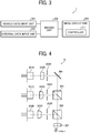
- FIG. 3 is a block diagram of a functional configuration of the display device 1 according to an embodiment of the present disclosure.
- the display device 1 according to the present disclosure includes a vehicle information input unit 201, an external information input unit 202, an image generator 203, and an image display unit 204.
- the vehicle information input unit 201 is a functional unit that obtains information (speed, traveling distance, and other information) of a car from, for example, the CAN.
- the vehicle information input unit 201 is implemented by, e.g., the I/F 105, the CPU 102, and a program stored in the ROM 103.
- the external information input unit 202 receives external information (for example, positional information from global positioning system (GPS), route information from a navigation system, and traffic information) of a car from external network.
- the external information input unit 202 is implemented by, e.g., the I/F 105, the CPU 102, and a program stored in the ROM 103.
- the image generator 203 is a function unit that determines a configuration of a virtual image 25 and generates display information for displaying the virtual image 25, based on the information obtained from the vehicle information input unit 201 and the external information input unit 202.
- the image generator 203 is implemented by, e.g., the I/F 105, the CPU 102, and a program stored in the ROM 103.
- the image display unit 204 is a functional unit that displays a virtual image 25 on a predetermined screen (the windshield 17 in the present embodiment) based on the display information generated by the image generator 203.
- the image display unit 204 is implemented by, for example, the CPU 102, the FPGA 101, the LD 109, the LD driver 110, the MEMS 111, and a MEMS controller 112.
- the image display unit 204 includes a controller 211 that is a functional unit that performs processing for adjusting, for example, the position and brightness of the virtual image 25.
- the controller 211 generates a signal for controlling, for example, the FPGA 101, the LD driver 110, and the MEMS controller 112.
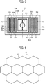
- FIG. 4 is an illustration of a specific configuration of the light source section 11 according to at least one embodiment.
- the light source section 11 according to the present embodiment includes light source elements 301R, 301G, 301B, coupling lenses 302R, 302G, 302B, apertures 303R, 303G, 303B, combining elements 304, 305, 306, and a lens 307.
- the light source elements 301R, 301G, 301B of three colors are LDs each having one or more light emitting points, and emits light beams having different wavelengths ⁇ R, ⁇ G, ⁇ B (for example, ⁇ R is 640 nanometers (nm), ⁇ G is 530 nm, ⁇ B is 445 nm).
- the emitted light beams are coupled by the coupling lenses 302R, 302G, and 302B, respectively.
- the coupled light beams are shaped by the apertures 303R, 303G, and 303B, respectively.
- Each of the apertures 303R, 303G, 303B has a shape (for example, a circle, an ellipse, a rectangle, or a square) according to prescribed conditions of, for example, the divergence angle of the light beam.
- the light beams shaped by the apertures 303R, 303G, 303B are combined by the three combining elements 304, 305, and 306, respectively.
- Each of the combining elements 304, 305, and 306 is a plate-like or prismatic dichroic mirror to reflect or transmit the corresponding light beam therethrough according to the wavelength of the light beam, and thus combine the light beams into one light beam that travels along one optical path.
- the combined light beam passes through the lens 307 and is directed to the scanning mirror 12.
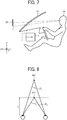
- FIG. 5 is an illustration of a specific configuration of the scanning mirror 12 according to an embodiment of the present disclosure.
- the scanning mirror 12 according to the present embodiment is a MEMS mirror manufactured by a semiconductor process and includes a mirror 351, a serpentine beam 352, a frame member 353, and a piezoelectric member 354.
- the mirror 351 has a reflecting surface that reflects a laser beam emitted from the light source section 11 toward the screen 13.
- a pair of serpentine beams 352 is formed with the mirror 351 interposed therebetween.
- the serpentine beam 352 includes a plurality of turning portions, each constituted by a first beam 352a and a second beam 352b that are alternately disposed in the serpentine beam 352.
- the serpentine beam 352 is supported by the frame member 353.
- the piezoelectric member 354 is disposed to connect the adjacent first beam 352a with the second beam 352b.
- the piezoelectric member 354 applies different voltages to the first beam 352a and the second beam 352b to warp each of the beams 352a and 352b.
- the adjacent beams 352a and 352b are bent in different directions.
- the mirror 351 rotates in the vertical direction about the horizontal axis. This configuration allows an optical scanning in the vertical direction with a low voltage.
- An optical scanning in the horizontal direction, on the axis in the vertical direction, is performed with resonance using, for example, a torsion bar connected to the mirror 351.
- FIG. 6 is an illustration of a specific configuration of the screen 13 according to an embodiment of the present disclosure.
- the screen 13 according to the present embodiment has a microlens-array structure in which a plurality of microlenses 371 is arranged without gap, each microlens having a hexagon shape.
- the screen 13 diverges the laser beam emitted from the scanning mirror 12 at a predetermined divergence angle.
- the width of each microlens 371 (the distance between two opposed sides) is approximately 200 micrometer ( ⁇ m).
- Such a configuration that each microlens 371 has a hexagon shape allows the arrangement of the plurality of microlenses 371 with high density. Note that the shape of each microlens 371 is not limited to the hexagon shape.
- each microlens 371 has, for example, a rectangular shape, or a triangle shape.
- the configuration in which the plurality of microlenses 371 is regularly arranged is illustrated.
- the center of each microlens 371 is decentered, and the plurality of microlenses 371 is irregularly arranged.
- each microlens 371 has a different shape.
- Such a configuration allows enlarging and projecting an intermediate image formed on the screen 13, onto the windshield 17, thus to display a virtual image 25 in the real space.
- the geometric shape of the display information in the virtual image 25 is adjusted to match the real space. This allows the observer 10 to perceive the display information to be superimposed on the real space.
- FIG. 7 is an illustration for explaining the difficulties in assembling when the virtual image 25 is superimposed on the real space.
- the solid line indicates the positions of the virtual image 25 and the display device 1 when the virtual image 25 is superimposed on the real space
- the dot-dash line indicates the positions of the virtual image 25 and the display device 1 when the virtual image 25 is not superimposed on the real space.
- the angle (depression angle) at which the observer 10 looks down at the virtual image 25 is increased. This allows setting the display device 1 at a position relatively far from the observer 10 in the Z-axis direction.
- the display device 1 is to be set at a position relatively near the observer in the Z-axis direction.
- a meter mechanism, a pedal mechanism, an air conditioning mechanism, and a handle mechanism are disposed in an area on the side closer to the observer 10 in the dashboard. Accordingly, there is a limited space to install the display device 1 in this area. In view of such circumstances, there is a demand for downsizing of the display device 1, particularly in the Z-axis direction, so as to set the display device 1 near the observer 10.
- the display device 1 allows the observer 10 to perceive the display information in the virtual image 25 with the display information superimposed on the real space.
- the observer 10 visually recognizes the display information near the windshield 17, which causes disparity between the display information and the observation target, on which the display information is superimposed, in the real space.
- FIG. 8 is an illustration of a relation between a convergence angle ⁇ 1 corresponding to an image-forming position of an observation target 401 and a convergence angle ⁇ 2 corresponding to an image-forming position of display information 411.
- the convergence angle ⁇ 1 corresponding to the image-forming position of the observation target 401 in the real space refers to an angle formed by the lines of sight of both eyes of the observer 10 when the observer 10 visually observes the observation target 401.
- the convergence angle ⁇ 2 corresponding to the image-forming position of the display information 411 of the virtual image 25 refers to the lines of sight of both eyes of the observer 10 when the observer 10 visually observes the display information 411.
- the disparity angle ⁇ para is defined as
- the display device 1 is designed to obtain the disparity angle ⁇ para of 1 deg or less.
- the disparity angle ⁇ para is 1 deg or less.
- FIG. 9 is a graph of a relation between the distance (the distance to the target) from the viewpoint position to a target (including the observation target 401 and the display information 411) and the convergence angle. As illustrated by a curve 421, the convergence angle changes with the distance from the viewpoint position of the observer to the target. As illustrated in FIG. 9 , when the distance to the target (hereinafter, sometimes referred to as the target distance) is approximately 3800 mm, the convergence angle is approximately 1 deg. When the target distance (the distance from the viewpoint position to the imaging position of the observation target 401) falls within the range of the convergence angle of ⁇ 1 deg represented by the dotted chain line, the display information 411 is allowed to be displayed at any position in the real space that is viewable through the windshield 17 by the observer 10.
- the distance from the viewpoint position to the observation target 401 is 2000 mm or more, so as to satisfy the above-described conditions.
- the distance from the viewpoint position to the observation target 401 on which the display information 411 is desired to be superimposed is less than 2000 mm.
- the optical path length in the display device 1 is kept constant and the distance L is increased, the magnification of the optical system in the display device 1 increases.
- the optical path length is the length of the path of light that travels from the screen 13 on which the intermediate image is formed to the windshield 17 onto which the virtual image 25 is projected.
- the magnification of the optical system is the magnification with respect to the intermediate image of the virtual image 25.
- the magnification is a value ⁇ obtained by dividing the length of the virtual image 25 in the vertical direction by the length of the intermediate image or the screen 13 in the vertical direction, or a value ⁇ obtained by dividing the length of the virtual image 25 in the horizontal direction by the length of the intermediate image or the screen 13 in the horizontal direction.
- the display device 1 includes a first flat mirror 14 to increase the optical path length without the up-sizing of the display device 1.
- FIG. 10 is an illustration of an example configuration of a first flat mirror 14 according to an embodiment of the present disclosure.
- the first flat mirror 14 has a first reflective area 31, a second reflective area 32, and a common reflective area 33.
- the Z axis indicates the depth direction of the apparatus 1000 (a car in the present embodiment), and the direction parallel to the reflection direction of the light.
- the X axis indicates the lateral (vertical) direction of the apparatus 1000, and the direction perpendicular to the reflection direction of light.
- the reflection direction of light refers to a direction (travel direction) in which light reflected by the first flat mirror 14 travels, that is, a travel direction in which light emitted from the second flat mirror 15 is reflected by the first flat mirror 14 and is directed to the concave mirror 16 or light emitted from the concave mirror 16 is reflected by the first flat mirror 14 and is directed to the windshield 17.
- the first reflective area 31 is an area to reflect light emitted from the screen 13 to the concave mirror 16.
- the "light emitted from the screen 13" refers to light that has been emitted from the screen 13 and reflected by the second flat mirror 15.
- the light emitted from the screen 13 is directly delivered to the first flat mirror 14 without striking on the second flat mirror 15 (without the use of the second flat mirror 15).
- a mirror other than the second flat mirror 15 is disposed in the optical path from the screen 13 to the first flat mirror 14, and the light emitted from the screen 13 is reflected by the plurality of mirrors and is delivered to the first reflective area 31.
- the first reflective area 31 allows enlarging the virtual image 25 to a maximum size to be displayed.
- the second reflective area 32 is an area to reflect the light emitted from the concave mirror 16 to the windshield 17.
- the second reflective area 32 allows enlarging the virtual image 25 to a maximum size to be displayed.
- the common reflective area 33 is an area in which the first reflective area 31 overlaps with the second reflective area 32.
- the common reflective area 33 serves as an area (the first reflective area 31) to reflect the light emitted from the screen 13 to the concave mirror 16 and also as an area (the second reflective area 32) to reflect the light emitted from the concave mirror 16 to the windshield 17.
- the ratio of the common reflective area 33 to the entire reflecting surface of the first flat mirror 14 increases, the first flat mirror 14 decreases in size.
- the optical path length from the screen 13 that forms an intermediate image to the windshield 17 that displays the virtual image 25 advantageously increases. Further, with the configuration that includes the common reflective area 33, the first flat mirror 14 is advantageously downsized.
- FIG. 11 is an illustration of an example of incident angles ⁇ 1 and ⁇ 2 of light reflected by the first flat mirror 14 according to an embodiment of the present disclosure.
- the broken line indicates an optical path through which the central ray of the virtual image 25 propagates to the reference viewpoint of the observer 10.
- the light reflected by the second flat mirror 15 enters the first reflective area 31 on the first flat mirror 14 at the incident angle ⁇ 1.
- the incident angle ⁇ 1 is an incident angle obtained when observed from the YZ plane to the optical system (for example, the first flat mirror 14).
- the "light reflected by the second flat mirror 15" is an example of light emitted from the screen 13.
- the light emitted from the screen 13 is directly delivered to the first flat mirror 14, instead of the light emitted from the second flat mirror 15.
- a mirror other than the second flat mirror 15 is disposed in the optical path from the screen 13 to the first flat mirror 14, and the light emitted from the screen 13 is reflected by the plurality of mirrors and is delivered to the first reflective area 31.
- the incident angle ⁇ 2 is the incident angle obtained when observed from the YZ plane to the optical system (for example, the first 14).
- the display device 1 is designed to satisfy the relation of ⁇ 1> ⁇ 2.
- the space to mount the display device 1 in the apparatus 1000 such as a car is limited according to the arrangement of various devices as described above. Accordingly, in some cases, it is difficult to dispose the second flat mirror 15 (light source section 11) and the concave mirror 16 on the same side with respect to the position of the first flat mirror 14 in the Z-axis direction.
- the display device 1 is designed to satisfy the relation of ⁇ 1 > ⁇ 2, which allows the second flat mirror 15 (light source section 11) and the concave mirror 16 to be installed on different sides with respect to the first flat mirror 14, thus reducing the size of the display device 1.
- the incident angle ⁇ 1 is approximately 1.6 times as great as the incident angle ⁇ 2.
- the virtual image 25 increases in the size in the vertical direction as much as possible.
- the above-described advantage is substantially obtained.
- ⁇ 1 is less than 1.2 ⁇ ⁇ 2
- the lower area of the virtual image 25 is limited by an opening (an opening to guide the light emitted from the concave mirror 16 to the windshield 17) above the concave mirror 16 or the bonnet.
- ⁇ 1 is greater than 2.0 ⁇ ⁇ 2
- the upper area of the virtual image 25 is limited by an opening above the second flat mirror 15 (the light source section 11) or the bonnet.
- the diameter of the first reflective area 31 in the Z-axis direction (the direction parallel to the reflection direction of light) is Z1
- the diameter of the first reflective area 31 in the X-axis direction (the direction perpendicular to the reflection direction of light)
- the diameter of the second reflective area 32 in the X-axis direction is Z2
- the diameter of the second reflective area 32 in the X-axis direction is X2
- the relation of Z1 > Z2 Z1 is greater than Z2)
- the relation of X1 ⁇ X2 (X1 is less than X2) is satisfied.
- the relation of Z1 > Z2 and the relation of X1 ⁇ X2 are satisfied.
- the configuration that satisfies such relations allows the first reflective area 31 and the second reflective area 32 to overlap with each other, thereby forming the common reflective area 33.
- Z1/X1 (the ratio of Z1 to X1) is A1
- Z2/X2 (the ratio of Z2 to X2) is A2
- the relation of (A1/A2) ⁇ 2 is preferably satisfied.
- A1 is a value indicating the degree of compression of the first reflective area 31 in the Z axis direction
- A2 is a value indicating the degree of compression of the second reflective area in the Z axis direction.
- the incident angle ⁇ 2 at which light emitted from the concave mirror 16 enters the second reflective area 32 is made smaller than the incident angle ⁇ 1 at which light emitted from the second flat mirror 15 (the screen 13 when the second flat mirror 15 is not provided) enters the first reflective area 31.
- This configuration reduces the aberration of light emitted from the concave mirror 16, and increases the image quality of the virtual image 25.
- FIG. 12 is an illustration of an example in which the first flat mirror 14 according to an embodiment of the present disclosure (shown in right) is compared with a first flat mirror 515 according to a comparative example (shown in left).
- the first flat mirror 515 according to the comparative example there is no area where the first reflective area 31 and the second reflective area 32 overlap with each other.
- the first flat mirror 14 according to the embodiments of the present disclosure has the common reflective area 33 in which the first reflective area 31 and the second reflective area 32 overlap with each other.
- the Z-axis directional length of the first flat mirror 14 according to the embodiments of the present disclosure is shorter than the first flat mirror 515 according to the comparative example does.
- the sizes and shapes of the first reflective area 31 and the second reflective area 32 according to the comparative example are the same as those of the first reflective area 31 and the second reflective area 32 according to the embodiments of the present disclosure.
- the configuration according to the embodiments of the present disclosure allows downsizing of the first flat mirror 14 and the display device 1 as a whole.
- the optical path length from the screen 13 that forms an intermediate image to the windshield 17 that displays the virtual image 25 advantageously increases.
- the configuration that includes the common reflective area 33 the first flat mirror 14 is advantageously downsized.
- the embodiments of the present disclosure increase the image quality of the virtual image 25 without an increase in size of the display device 1.
Landscapes
- Physics & Mathematics (AREA)
- General Physics & Mathematics (AREA)
- Optics & Photonics (AREA)
- Instrument Panels (AREA)
Applications Claiming Priority (2)
| Application Number | Priority Date | Filing Date | Title |
|---|---|---|---|
| JP2017039256 | 2017-03-02 | ||
| JP2017234180A JP2018146950A (ja) | 2017-03-02 | 2017-12-06 | 表示装置及び機器 |
Publications (1)
| Publication Number | Publication Date |
|---|---|
| EP3370103A1 true EP3370103A1 (fr) | 2018-09-05 |
Family
ID=61024690
Family Applications (1)
| Application Number | Title | Priority Date | Filing Date |
|---|---|---|---|
| EP18153278.9A Withdrawn EP3370103A1 (fr) | 2017-03-02 | 2018-01-24 | Dispositif d'affichage et appareil |
Country Status (2)
| Country | Link |
|---|---|
| US (1) | US10831021B2 (fr) |
| EP (1) | EP3370103A1 (fr) |
Families Citing this family (18)
| Publication number | Priority date | Publication date | Assignee | Title |
|---|---|---|---|---|
| JP2018156062A (ja) | 2017-03-15 | 2018-10-04 | 株式会社リコー | 表示装置、物体装置及び表示方法 |
| US10303045B1 (en) | 2017-12-20 | 2019-05-28 | Micron Technology, Inc. | Control of display device for autonomous vehicle |
| JP2019158991A (ja) | 2018-03-09 | 2019-09-19 | 株式会社リコー | 表示装置、表示システムおよび移動体 |
| JP7047491B2 (ja) | 2018-03-12 | 2022-04-05 | 株式会社リコー | 投射装置、移動体および投射装置の設置方法 |
| JP2019159100A (ja) | 2018-03-13 | 2019-09-19 | 株式会社リコー | 光走査装置、画像表示装置、ヘッドアップディスプレイ、及び移動体 |
| JP7037760B2 (ja) | 2018-03-16 | 2022-03-17 | 株式会社リコー | 画像投写装置及び移動体 |
| JP7015475B2 (ja) | 2018-03-16 | 2022-02-15 | 株式会社リコー | 光走査装置、画像投写装置及び移動体 |
| JP7000937B2 (ja) | 2018-03-16 | 2022-01-19 | 株式会社リコー | 表示装置及び機器 |
| JP7101341B2 (ja) | 2018-03-19 | 2022-07-15 | 株式会社リコー | 画像投写装置及び移動体 |
| JP7202539B2 (ja) | 2018-03-19 | 2023-01-12 | 株式会社リコー | 画像表示装置、画像投写装置及び移動体 |
| JP2019164239A (ja) | 2018-03-19 | 2019-09-26 | 株式会社リコー | 表示装置及び機器 |
| JP2019164180A (ja) | 2018-03-19 | 2019-09-26 | 株式会社リコー | 光走査装置、画像表示装置、ヘッドアップディスプレイ、及び移動体 |
| JP6866875B2 (ja) * | 2018-05-29 | 2021-04-28 | 株式会社デンソー | 表示制御装置、及び表示制御プログラム |
| EP3657232B1 (fr) | 2018-11-08 | 2023-01-04 | Ricoh Company, Ltd. | Dispositif d'affichage, système d'affichage et objet mobile |
| JP7180557B2 (ja) | 2019-07-04 | 2022-11-30 | 株式会社デンソー | 虚像表示装置 |
| US11953816B2 (en) | 2021-08-06 | 2024-04-09 | Ricoh Company, Ltd. | Wavelength conversion plate, light source device, and image projection apparatus |
| DE102021131756A1 (de) * | 2021-12-02 | 2023-06-07 | Ford Global Technologies Llc | Baugruppe für ein Kraftfahrzeug |
| US20230393396A1 (en) * | 2022-06-02 | 2023-12-07 | Harman International Industries, Incorporated | Automatic eye height adjustment |
Citations (3)
| Publication number | Priority date | Publication date | Assignee | Title |
|---|---|---|---|---|
| FR2844061A1 (fr) * | 2002-09-02 | 2004-03-05 | Valeo Vision | "dispositif de restitution d'image de type vision tete haute, en particulier pour vehicule automobile". |
| JP2009115908A (ja) | 2007-11-02 | 2009-05-28 | Fujinon Corp | ミラー光学系及びヘッドアップディスプレイ装置 |
| US20160266383A1 (en) * | 2013-11-06 | 2016-09-15 | Denso Corporation | Head-up display device |
Family Cites Families (12)
| Publication number | Priority date | Publication date | Assignee | Title |
|---|---|---|---|---|
| US5357372A (en) * | 1992-04-07 | 1994-10-18 | Hughes Aircraft Company | Ultra-compact, wide field of view virtual image display optical system |
| US5734506A (en) * | 1996-08-19 | 1998-03-31 | Delco Electronics Corporation | Head up display projection system having a double reflecting primary mirror |
| JP5842419B2 (ja) * | 2011-07-06 | 2016-01-13 | 日本精機株式会社 | ヘッドアップディスプレイ装置 |
| US9158124B2 (en) | 2012-12-21 | 2015-10-13 | Ricoh Company, Ltd. | Image display device and vehicle incorporating the same |
| JP5682692B2 (ja) | 2012-12-21 | 2015-03-11 | 株式会社リコー | 画像表示装置 |
| JP6315240B2 (ja) | 2014-02-03 | 2018-04-25 | 株式会社リコー | 画像表示装置、移動体及びレンズアレイ |
| JP6340807B2 (ja) | 2014-02-05 | 2018-06-13 | 株式会社リコー | 画像表示装置及び移動体 |
| JP6555507B2 (ja) | 2014-05-12 | 2019-08-07 | 株式会社リコー | 画像表示装置及び移動体 |
| JP6504353B2 (ja) | 2015-04-28 | 2019-04-24 | 株式会社リコー | 画像表示装置及び物体装置 |
| JP2017097268A (ja) | 2015-11-27 | 2017-06-01 | 株式会社リコー | 画像表示装置および車両 |
| US9958677B2 (en) * | 2015-12-25 | 2018-05-01 | Panasonic Intellectual Property Management Co., Ltd. | Head-up display and mobile object equipped with head-up display |
| JP6521879B2 (ja) * | 2016-01-26 | 2019-05-29 | 富士フイルム株式会社 | ヘッドアップディスプレイ装置 |
-
2018
- 2018-01-24 EP EP18153278.9A patent/EP3370103A1/fr not_active Withdrawn
- 2018-02-01 US US15/886,401 patent/US10831021B2/en active Active
Patent Citations (3)
| Publication number | Priority date | Publication date | Assignee | Title |
|---|---|---|---|---|
| FR2844061A1 (fr) * | 2002-09-02 | 2004-03-05 | Valeo Vision | "dispositif de restitution d'image de type vision tete haute, en particulier pour vehicule automobile". |
| JP2009115908A (ja) | 2007-11-02 | 2009-05-28 | Fujinon Corp | ミラー光学系及びヘッドアップディスプレイ装置 |
| US20160266383A1 (en) * | 2013-11-06 | 2016-09-15 | Denso Corporation | Head-up display device |
Also Published As
| Publication number | Publication date |
|---|---|
| US10831021B2 (en) | 2020-11-10 |
| US20180252916A1 (en) | 2018-09-06 |
Similar Documents
| Publication | Publication Date | Title |
|---|---|---|
| EP3370103A1 (fr) | Dispositif d'affichage et appareil | |
| JP7027856B2 (ja) | 表示装置及び機器 | |
| EP2945001B1 (fr) | Dispositif d'affichage tête haute avec déformation en cisaillement introduite dans une image intermédiare | |
| EP2944986B1 (fr) | Appareil et système d'affichage d'images | |
| CN104685405B (zh) | 用于车辆的视野显示装置 | |
| JP7715889B2 (ja) | ヘッドアップディスプレイ | |
| JP6638198B2 (ja) | 画像表示装置及び移動体 | |
| EP3835848B1 (fr) | Affichage " tête haute | |
| EP3605191B1 (fr) | Dispositif d'affichage d'image virtuelle | |
| EP3684054B1 (fr) | Appareil de projection et objet mobile | |
| JP6735023B2 (ja) | 表示画像作成装置および画像表示装置 | |
| WO2018066675A1 (fr) | Système optique de projection à grossissement variable et dispositif d'affichage d'image | |
| US20240151955A1 (en) | Image projection device | |
| JP2021015132A (ja) | ヘッドアップディスプレイ装置 | |
| EP3006988B1 (fr) | Appareil d'affichage d'images | |
| JP6710017B2 (ja) | 画像表示装置 | |
| US20190219820A1 (en) | Image display apparatus and mobile apparatus | |
| JP2018146950A (ja) | 表示装置及び機器 | |
| EP3964882B1 (fr) | Afficheur de véhicule | |
| WO2018186149A1 (fr) | Système d'affichage tête haute, et objet mobile équipé du système d'affichage tête haute | |
| US20200132983A1 (en) | Display device, display system, and mobile object | |
| US11231582B2 (en) | Display device, display system, and mobile object | |
| EP3534202B1 (fr) | Dispositif d'affichage d'image virtuelle | |
| CN109154719B (zh) | 投影光学系统、抬头显示器装置以及汽车 | |
| WO2018155138A1 (fr) | Appareil d'affichage et équipement |
Legal Events
| Date | Code | Title | Description |
|---|---|---|---|
| PUAI | Public reference made under article 153(3) epc to a published international application that has entered the european phase |
Free format text: ORIGINAL CODE: 0009012 |
|
| STAA | Information on the status of an ep patent application or granted ep patent |
Free format text: STATUS: REQUEST FOR EXAMINATION WAS MADE |
|
| 17P | Request for examination filed |
Effective date: 20180124 |
|
| AK | Designated contracting states |
Kind code of ref document: A1 Designated state(s): AL AT BE BG CH CY CZ DE DK EE ES FI FR GB GR HR HU IE IS IT LI LT LU LV MC MK MT NL NO PL PT RO RS SE SI SK SM TR |
|
| AX | Request for extension of the european patent |
Extension state: BA ME |
|
| RAP1 | Party data changed (applicant data changed or rights of an application transferred) |
Owner name: RICOH COMPANY, LTD. |
|
| STAA | Information on the status of an ep patent application or granted ep patent |
Free format text: STATUS: THE APPLICATION HAS BEEN WITHDRAWN |
|
| 18W | Application withdrawn |
Effective date: 20210111 |