EP3370638B1 - Appareil orthodontique à mémoire de forme continue - Google Patents
Appareil orthodontique à mémoire de forme continue Download PDFInfo
- Publication number
- EP3370638B1 EP3370638B1 EP16862796.6A EP16862796A EP3370638B1 EP 3370638 B1 EP3370638 B1 EP 3370638B1 EP 16862796 A EP16862796 A EP 16862796A EP 3370638 B1 EP3370638 B1 EP 3370638B1
- Authority
- EP
- European Patent Office
- Prior art keywords
- appliance
- teeth
- arrangement
- patient
- model
- Prior art date
- Legal status (The legal status is an assumption and is not a legal conclusion. Google has not performed a legal analysis and makes no representation as to the accuracy of the status listed.)
- Active
Links
- 238000000034 method Methods 0.000 claims description 78
- 238000000465 moulding Methods 0.000 claims description 57
- 239000000463 material Substances 0.000 claims description 39
- 229920000642 polymer Polymers 0.000 claims description 32
- 210000002455 dental arch Anatomy 0.000 claims description 28
- 238000002425 crystallisation Methods 0.000 claims description 26
- 230000008025 crystallization Effects 0.000 claims description 26
- 230000007704 transition Effects 0.000 claims description 25
- 238000004519 manufacturing process Methods 0.000 claims description 19
- 229920000431 shape-memory polymer Polymers 0.000 claims description 17
- 238000010438 heat treatment Methods 0.000 claims description 16
- 238000004132 cross linking Methods 0.000 claims description 7
- 230000002829 reductive effect Effects 0.000 claims description 6
- 239000000126 substance Substances 0.000 claims description 6
- 238000001816 cooling Methods 0.000 claims description 4
- 210000004513 dentition Anatomy 0.000 claims description 4
- 230000036346 tooth eruption Effects 0.000 claims description 4
- 238000011084 recovery Methods 0.000 claims description 3
- 239000012781 shape memory material Substances 0.000 claims description 3
- 238000003825 pressing Methods 0.000 claims 1
- 230000008569 process Effects 0.000 description 28
- 230000033001 locomotion Effects 0.000 description 19
- 238000003860 storage Methods 0.000 description 10
- 239000013078 crystal Substances 0.000 description 6
- 230000006870 function Effects 0.000 description 6
- -1 polyethylene Polymers 0.000 description 6
- 239000000523 sample Substances 0.000 description 6
- 210000001519 tissue Anatomy 0.000 description 6
- 238000005266 casting Methods 0.000 description 5
- 230000003247 decreasing effect Effects 0.000 description 5
- 238000003384 imaging method Methods 0.000 description 5
- 239000004698 Polyethylene Substances 0.000 description 4
- 230000007246 mechanism Effects 0.000 description 4
- 238000002844 melting Methods 0.000 description 4
- 230000008018 melting Effects 0.000 description 4
- 229920000573 polyethylene Polymers 0.000 description 4
- 230000005855 radiation Effects 0.000 description 4
- 230000015572 biosynthetic process Effects 0.000 description 3
- 238000004590 computer program Methods 0.000 description 3
- 230000001419 dependent effect Effects 0.000 description 3
- 229920001971 elastomer Polymers 0.000 description 3
- 239000000806 elastomer Substances 0.000 description 3
- 230000003993 interaction Effects 0.000 description 3
- 150000002978 peroxides Chemical class 0.000 description 3
- 230000009467 reduction Effects 0.000 description 3
- 239000002904 solvent Substances 0.000 description 3
- CSCPPACGZOOCGX-UHFFFAOYSA-N Acetone Chemical compound CC(C)=O CSCPPACGZOOCGX-UHFFFAOYSA-N 0.000 description 2
- IJGRMHOSHXDMSA-UHFFFAOYSA-N Atomic nitrogen Chemical compound N#N IJGRMHOSHXDMSA-UHFFFAOYSA-N 0.000 description 2
- 206010061274 Malocclusion Diseases 0.000 description 2
- 238000013459 approach Methods 0.000 description 2
- 230000008901 benefit Effects 0.000 description 2
- 230000036760 body temperature Effects 0.000 description 2
- 230000008859 change Effects 0.000 description 2
- 238000002591 computed tomography Methods 0.000 description 2
- 230000006378 damage Effects 0.000 description 2
- 238000013500 data storage Methods 0.000 description 2
- 238000000151 deposition Methods 0.000 description 2
- 230000008021 deposition Effects 0.000 description 2
- 238000013461 design Methods 0.000 description 2
- 238000010894 electron beam technology Methods 0.000 description 2
- 230000001815 facial effect Effects 0.000 description 2
- 230000009477 glass transition Effects 0.000 description 2
- 230000005865 ionizing radiation Effects 0.000 description 2
- 230000001678 irradiating effect Effects 0.000 description 2
- 238000005259 measurement Methods 0.000 description 2
- 230000001483 mobilizing effect Effects 0.000 description 2
- 230000037361 pathway Effects 0.000 description 2
- 229920003023 plastic Polymers 0.000 description 2
- 239000004033 plastic Substances 0.000 description 2
- 230000000750 progressive effect Effects 0.000 description 2
- 230000000717 retained effect Effects 0.000 description 2
- 238000000110 selective laser sintering Methods 0.000 description 2
- 229920006126 semicrystalline polymer Polymers 0.000 description 2
- 238000000547 structure data Methods 0.000 description 2
- 230000010512 thermal transition Effects 0.000 description 2
- 229920001169 thermoplastic Polymers 0.000 description 2
- 239000004416 thermosoftening plastic Substances 0.000 description 2
- 230000001960 triggered effect Effects 0.000 description 2
- FHVDTGUDJYJELY-UHFFFAOYSA-N 6-{[2-carboxy-4,5-dihydroxy-6-(phosphanyloxy)oxan-3-yl]oxy}-4,5-dihydroxy-3-phosphanyloxane-2-carboxylic acid Chemical compound O1C(C(O)=O)C(P)C(O)C(O)C1OC1C(C(O)=O)OC(OP)C(O)C1O FHVDTGUDJYJELY-UHFFFAOYSA-N 0.000 description 1
- 239000004677 Nylon Substances 0.000 description 1
- 239000004743 Polypropylene Substances 0.000 description 1
- 102100022432 Sclerostin domain-containing protein 1 Human genes 0.000 description 1
- BLRPTPMANUNPDV-UHFFFAOYSA-N Silane Chemical compound [SiH4] BLRPTPMANUNPDV-UHFFFAOYSA-N 0.000 description 1
- 241001024096 Uleiota Species 0.000 description 1
- 239000004699 Ultra-high molecular weight polyethylene Substances 0.000 description 1
- 208000027418 Wounds and injury Diseases 0.000 description 1
- 238000005299 abrasion Methods 0.000 description 1
- 230000004308 accommodation Effects 0.000 description 1
- 229940072056 alginate Drugs 0.000 description 1
- 229920000615 alginic acid Polymers 0.000 description 1
- 235000010443 alginic acid Nutrition 0.000 description 1
- 125000005233 alkylalcohol group Chemical group 0.000 description 1
- 230000006399 behavior Effects 0.000 description 1
- 230000009286 beneficial effect Effects 0.000 description 1
- 238000004422 calculation algorithm Methods 0.000 description 1
- 238000004364 calculation method Methods 0.000 description 1
- 238000004891 communication Methods 0.000 description 1
- 238000005094 computer simulation Methods 0.000 description 1
- 239000000470 constituent Substances 0.000 description 1
- 238000012937 correction Methods 0.000 description 1
- 238000010168 coupling process Methods 0.000 description 1
- 238000003745 diagnosis Methods 0.000 description 1
- 230000000694 effects Effects 0.000 description 1
- 238000001652 electrophoretic deposition Methods 0.000 description 1
- 238000005516 engineering process Methods 0.000 description 1
- 239000003822 epoxy resin Substances 0.000 description 1
- 239000005038 ethylene vinyl acetate Substances 0.000 description 1
- 238000011156 evaluation Methods 0.000 description 1
- 239000012530 fluid Substances 0.000 description 1
- 230000008570 general process Effects 0.000 description 1
- 210000004195 gingiva Anatomy 0.000 description 1
- 238000010348 incorporation Methods 0.000 description 1
- 239000011261 inert gas Substances 0.000 description 1
- 208000014674 injury Diseases 0.000 description 1
- 230000009878 intermolecular interaction Effects 0.000 description 1
- 210000001847 jaw Anatomy 0.000 description 1
- 239000007788 liquid Substances 0.000 description 1
- 238000002595 magnetic resonance imaging Methods 0.000 description 1
- 230000014759 maintenance of location Effects 0.000 description 1
- 239000000155 melt Substances 0.000 description 1
- 239000000203 mixture Substances 0.000 description 1
- 238000012986 modification Methods 0.000 description 1
- 230000004048 modification Effects 0.000 description 1
- 239000003607 modifier Substances 0.000 description 1
- 229910052757 nitrogen Inorganic materials 0.000 description 1
- 229910052756 noble gas Inorganic materials 0.000 description 1
- 150000002835 noble gases Chemical class 0.000 description 1
- 229920001778 nylon Polymers 0.000 description 1
- 230000003287 optical effect Effects 0.000 description 1
- 239000005022 packaging material Substances 0.000 description 1
- 230000036961 partial effect Effects 0.000 description 1
- 230000000704 physical effect Effects 0.000 description 1
- 229920000647 polyepoxide Polymers 0.000 description 1
- 229920005638 polyethylene monopolymer Polymers 0.000 description 1
- 229920001155 polypropylene Polymers 0.000 description 1
- 238000012805 post-processing Methods 0.000 description 1
- 238000002360 preparation method Methods 0.000 description 1
- 238000007639 printing Methods 0.000 description 1
- 238000012545 processing Methods 0.000 description 1
- 230000002250 progressing effect Effects 0.000 description 1
- 238000002601 radiography Methods 0.000 description 1
- 230000008707 rearrangement Effects 0.000 description 1
- 230000001373 regressive effect Effects 0.000 description 1
- 229920005989 resin Polymers 0.000 description 1
- 239000011347 resin Substances 0.000 description 1
- 238000005070 sampling Methods 0.000 description 1
- 238000000926 separation method Methods 0.000 description 1
- 229910000077 silane Inorganic materials 0.000 description 1
- 150000004756 silanes Chemical class 0.000 description 1
- 230000003068 static effect Effects 0.000 description 1
- 239000004575 stone Substances 0.000 description 1
- 230000001360 synchronised effect Effects 0.000 description 1
- 230000001225 therapeutic effect Effects 0.000 description 1
- 238000002560 therapeutic procedure Methods 0.000 description 1
- 229920001187 thermosetting polymer Polymers 0.000 description 1
- 210000000332 tooth crown Anatomy 0.000 description 1
- 238000013519 translation Methods 0.000 description 1
- 229920000785 ultra high molecular weight polyethylene Polymers 0.000 description 1
- 238000012285 ultrasound imaging Methods 0.000 description 1
- 230000000007 visual effect Effects 0.000 description 1
- XLYOFNOQVPJJNP-UHFFFAOYSA-N water Substances O XLYOFNOQVPJJNP-UHFFFAOYSA-N 0.000 description 1
Images


Classifications
-
- A—HUMAN NECESSITIES
- A61—MEDICAL OR VETERINARY SCIENCE; HYGIENE
- A61C—DENTISTRY; APPARATUS OR METHODS FOR ORAL OR DENTAL HYGIENE
- A61C7/00—Orthodontics, i.e. obtaining or maintaining the desired position of teeth, e.g. by straightening, evening, regulating, separating, or by correcting malocclusions
- A61C7/08—Mouthpiece-type retainers or positioners, e.g. for both the lower and upper arch
-
- A—HUMAN NECESSITIES
- A61—MEDICAL OR VETERINARY SCIENCE; HYGIENE
- A61C—DENTISTRY; APPARATUS OR METHODS FOR ORAL OR DENTAL HYGIENE
- A61C7/00—Orthodontics, i.e. obtaining or maintaining the desired position of teeth, e.g. by straightening, evening, regulating, separating, or by correcting malocclusions
- A61C7/002—Orthodontic computer assisted systems
-
- A—HUMAN NECESSITIES
- A61—MEDICAL OR VETERINARY SCIENCE; HYGIENE
- A61C—DENTISTRY; APPARATUS OR METHODS FOR ORAL OR DENTAL HYGIENE
- A61C9/00—Impression cups, i.e. impression trays; Impression methods
- A61C9/0006—Impression trays
-
- A—HUMAN NECESSITIES
- A61—MEDICAL OR VETERINARY SCIENCE; HYGIENE
- A61C—DENTISTRY; APPARATUS OR METHODS FOR ORAL OR DENTAL HYGIENE
- A61C9/00—Impression cups, i.e. impression trays; Impression methods
- A61C9/004—Means or methods for taking digitized impressions
- A61C9/0046—Data acquisition means or methods
- A61C9/0053—Optical means or methods, e.g. scanning the teeth by a laser or light beam
-
- B—PERFORMING OPERATIONS; TRANSPORTING
- B29—WORKING OF PLASTICS; WORKING OF SUBSTANCES IN A PLASTIC STATE IN GENERAL
- B29C—SHAPING OR JOINING OF PLASTICS; SHAPING OF MATERIAL IN A PLASTIC STATE, NOT OTHERWISE PROVIDED FOR; AFTER-TREATMENT OF THE SHAPED PRODUCTS, e.g. REPAIRING
- B29C51/00—Shaping by thermoforming, i.e. shaping sheets or sheet like preforms after heating, e.g. shaping sheets in matched moulds or by deep-drawing; Apparatus therefor
- B29C51/10—Forming by pressure difference, e.g. vacuum
-
- B—PERFORMING OPERATIONS; TRANSPORTING
- B29—WORKING OF PLASTICS; WORKING OF SUBSTANCES IN A PLASTIC STATE IN GENERAL
- B29C—SHAPING OR JOINING OF PLASTICS; SHAPING OF MATERIAL IN A PLASTIC STATE, NOT OTHERWISE PROVIDED FOR; AFTER-TREATMENT OF THE SHAPED PRODUCTS, e.g. REPAIRING
- B29C51/00—Shaping by thermoforming, i.e. shaping sheets or sheet like preforms after heating, e.g. shaping sheets in matched moulds or by deep-drawing; Apparatus therefor
- B29C51/26—Component parts, details or accessories; Auxiliary operations
- B29C51/42—Heating or cooling
- B29C51/421—Heating or cooling of preforms, specially adapted for thermoforming
-
- A—HUMAN NECESSITIES
- A61—MEDICAL OR VETERINARY SCIENCE; HYGIENE
- A61C—DENTISTRY; APPARATUS OR METHODS FOR ORAL OR DENTAL HYGIENE
- A61C19/00—Dental auxiliary appliances
- A61C19/003—Apparatus for curing resins by radiation
-
- A—HUMAN NECESSITIES
- A61—MEDICAL OR VETERINARY SCIENCE; HYGIENE
- A61C—DENTISTRY; APPARATUS OR METHODS FOR ORAL OR DENTAL HYGIENE
- A61C2201/00—Material properties
- A61C2201/007—Material properties using shape memory effect
-
- A—HUMAN NECESSITIES
- A61—MEDICAL OR VETERINARY SCIENCE; HYGIENE
- A61C—DENTISTRY; APPARATUS OR METHODS FOR ORAL OR DENTAL HYGIENE
- A61C9/00—Impression cups, i.e. impression trays; Impression methods
- A61C9/002—Means or methods for correctly replacing a dental model, e.g. dowel pins; Dowel pin positioning means or methods
-
- B—PERFORMING OPERATIONS; TRANSPORTING
- B29—WORKING OF PLASTICS; WORKING OF SUBSTANCES IN A PLASTIC STATE IN GENERAL
- B29C—SHAPING OR JOINING OF PLASTICS; SHAPING OF MATERIAL IN A PLASTIC STATE, NOT OTHERWISE PROVIDED FOR; AFTER-TREATMENT OF THE SHAPED PRODUCTS, e.g. REPAIRING
- B29C2791/00—Shaping characteristics in general
- B29C2791/001—Shaping in several steps
-
- B—PERFORMING OPERATIONS; TRANSPORTING
- B29—WORKING OF PLASTICS; WORKING OF SUBSTANCES IN A PLASTIC STATE IN GENERAL
- B29C—SHAPING OR JOINING OF PLASTICS; SHAPING OF MATERIAL IN A PLASTIC STATE, NOT OTHERWISE PROVIDED FOR; AFTER-TREATMENT OF THE SHAPED PRODUCTS, e.g. REPAIRING
- B29C51/00—Shaping by thermoforming, i.e. shaping sheets or sheet like preforms after heating, e.g. shaping sheets in matched moulds or by deep-drawing; Apparatus therefor
- B29C51/26—Component parts, details or accessories; Auxiliary operations
- B29C51/42—Heating or cooling
- B29C51/426—Producing specific thermal regimes during thermoforming to obtain particular properties
-
- B—PERFORMING OPERATIONS; TRANSPORTING
- B29—WORKING OF PLASTICS; WORKING OF SUBSTANCES IN A PLASTIC STATE IN GENERAL
- B29L—INDEXING SCHEME ASSOCIATED WITH SUBCLASS B29C, RELATING TO PARTICULAR ARTICLES
- B29L2031/00—Other particular articles
- B29L2031/753—Medical equipment; Accessories therefor
Definitions
- Orthodontics is a specialized area of dentistry concerned with the diagnosis and treatment of dental malocclusions to improve bite function, hygiene, and facial aesthetics.
- Orthodontic therapy commonly uses appliances called brackets and molar tubes which are bonded to a patient's teeth. Brackets and molar tubes contain slots and passageways, respectively, to accommodate a resilient "U"-shaped wire called an orthodontic archwire.
- the archwire is secured within the slots and passageways of the brackets and molar tubes. While the archwire is initially distorted, it gradually returns to its original shape over the course of treatment, thereby applying therapeutic forces to urge the malpositioned teeth to proper locations.
- Another type of orthodontic treatment involves the use of resilient polymeric trays that fit over the teeth of the patient's dental arches.
- These trays also known as aligners, alignment shells and polymeric appliances, are provided in a series and are intended to be worn in succession in order to gradually move the teeth in incremental steps toward a desired target arrangement.
- Some types of polymeric appliances have a row of tooth-shaped cavities for receiving each tooth of the patient's dental arch, and the cavities are oriented in slightly different positions from one appliance to the next in order to incrementally urge each tooth toward its desired target position by virtue of the resilient properties of the polymeric material.
- a digital data file is obtained that represents the patient's upper and lower dental arches at the beginning of treatment. This data file is then analyzed to identify subsets of data, each of which represents one of the patient's teeth.
- a technician uses a computer input device (such as a mouse or keyboard) to virtually reposition the maloccluded teeth and move individual teeth on a computer screen relative to each other into desired target positions. The target positions are then reviewed and approved by a treating professional, such as an orthodontist that is located remotely from the technician.
- Document WO00/32131 shows a polymeric shell dental appliance with a concave trough having a first state, wherein the concave trough comprises a memory polymer configured to convert the concave trough to a second state on application of an external energy stimulus.
- the data representing the initial tooth positions and the data representing the target tooth positions are then used to determine intended intermediate positions of the teeth as the teeth move from initial to target positions.
- data representing the differences in tooth positions between the initial tooth arrangement and the target tooth arrangement may be interpolated in order to obtain a series of twenty intermediate positions of the teeth.
- the data representing those intermediate tooth positions is then stored in memory and subsequently used to make models of the dental arches for each intermediate tooth arrangement.
- a data set representing the teeth in a desired target arrangement and twenty data sets representing the teeth in twenty different intermediate arrangements may be used to manufacture a series of twenty-one physical, positive dental arch models for each dental arch using rapid prototyping methods such as stereolithography.
- a sheet of polymeric material is placed over each of the arch models and formed under heat, pressure and/or vacuum to conform to the model teeth of each model arch.
- the formed sheet is cleaned and trimmed as needed and the resulting arch-shaped appliance is shipped along with the remaining appliances to the treating professional.
- the patient is then instructed to wear each appliance over its intended dental arch in sequence for a period of, for example, two or four weeks, after which the used appliances are discarded and the next two appliances in the series for the upper and lower dental arches are to be worn.
- Typical polymeric appliances are configured to store one or two shapes corresponding to different arrangements of the patient's teeth. This requires the patient to continually replace the worn appliance with a subsequent appliance to ensure the application of continued, clinically effective force on the relevant teeth. Such limited shape storage also requires that any given appliance only move the teeth a limited amount (e.g., 0.2 mm), and particularly complicated malocclusion may require an excess number of appliances to treat.
- the present disclosure provides continuous adjustment appliances that can store a large number of geometries that can be successively accessed throughout treatment. Each geometry can correspond to an arrangement of the patient's teeth.
- An appliance according to the present disclosure can be stimulated to transition among myriad geometries, which can include changes to the overall shape of the appliance as well as the position and geometry of the cavities corresponding to a patient's teeth. This variability allows the patient or practitioner to vary the differences between given successive tooth arrangements to expand or contract the length of time the patient wears a given configuration before needing to transition to the next appliance configuration.
- the appliance can be manufactured to store at least 4, at least 6, at least 10, at least 20, and at least 30 distinct appliance geometries.
- the ability to store multiple geometries in a single appliance is a distinct advantage, as it allows for more iterations of movement between any given tooth orientation. This can have the effect of both making treatment more efficient, in certain implementations, as well as improving comfort for the patient.
- Appliances of the present disclosure can also be formed from materials that are softer than typically used to create polymeric appliances, which can also lead to an increase in patient comfort and compliance. Furthermore, by requiring fewer appliances to perform the same treatment goals, the continuous adjustment appliances of the present disclosure can reduce the material and manufacturing cost associated with any given treatment.
- the present invention provides a polymeric shell dental appliance for placement on a dental arch comprising a concave trough having cavities configured to be positioned on a plurality of teeth in the dental arch and having a first approximate shape, wherein the concave trough comprises a crosslinked shape memory polymer, and wherein the crosslinked shape memory polymer is a semicrystalline, non-segmented polymer configured to restore the concave trough to (a) a second approximate shape on application of a first external energy stimulus; and (b) a third approximate shape on application of a second external energy stimulus of a greater magnitude than the first energy stimulus.
- the present invention provides a method for manufacturing polymeric dental appliances configured to conform to one or more teeth of a patient.
- the method comprises providing a first positive model of the patient's dentition, the model representing a repositioned arrangement of the patient's teeth and forming over the model at a first molding temperature a sheet of crosslinkable, crystallizable polymeric material having a crystallization temperature range having an upper limit and a lower limit.
- the method next involves crosslinking the polymer to create an appliance having a first stored geometry.
- a second model representing a first intermediate arrangement of the patient's teeth is provided, with the arrangement including one or more teeth in different orientations than the first model.
- the appliance is subjected to a second molding temperature within the crystallization temperature range to create an appliance having a second stored geometry.
- the method next includes the steps of providing a third model representing a second intermediate arrangement of the patient's teeth, the second arrangement including one or more teeth in different orientations than the first intermediate arrangement, subjecting the appliance to a third molding temperature within the crystallization temperature range to create a third stored geometry, the third molding temperature being less than either the first or second molding temperatures; and cooling the appliance below the lower limit of transition temperature range.
- the present disclosure provides a method of moving a patient's teeth of a target arrangement.
- the method includes placing a polymeric dental appliance having a first configuration on a dental arch, the polymeric appliance comprising a crosslinked, semicrystalline shape memory polymer having a number of crosslinks and crystalline structures; heating the appliance to a first transition temperature so as to modify the shape of the appliance to a second configuration. Once the appliance reaches the second configuration, it is placed on the dental arch. Subsequently, the appliance is heated to a second transition temperature so as to modify the shape of the shell to a third configuration. The polymeric appliance in the third configuration is placed on the dental arch, with the third configuration shaped to reposition the patient's teeth to the target arrangement.
- cross-linking polymeric material means a polymer, for example polyethylene, that can be cross-linked by a variety of approaches, including those employing cross-linking chemicals (such as peroxides and/or silane) and/or irradiation. Preferred approaches for cross-linking employ irradiation.
- the term "generally”, unless otherwise specifically defined, means that the property or attribute would be readily recognizable by a person of ordinary skill but without requiring absolute precision or a perfect match (e.g., within +/- 20 % for quantifiable properties).
- the term “substantially”, unless otherwise specifically defined, means to a high degree of approximation (e.g., within +/- 10% for quantifiable properties) but again without requiring absolute precision or a perfect match. Terms such as same, equal, uniform, constant, strictly, and the like, are understood to be within the usual tolerances or measuring error applicable to the particular circumstance rather than requiring absolute precision or a perfect match.
- the present disclosure provides continuous adjustment appliances that can store a large number of geometries that can be successively accessed throughout treatment.
- Each geometry can correspond to an arrangement of the patient's teeth.
- each arrangement of teeth requires the use of a new appliance.
- an appliance according to the present disclosure can be stimulated to transition among myriad geometries, which can include changes to the overall shape of the appliance as well as the position and geometry of the cavities corresponding to a patient's teeth.
- the continuous adjustment appliance 100 is removable and replaceable over the teeth.
- appliance 100 is one of a plurality of incremental adjustment appliances.
- the continuous adjustment appliance 100 may comprise a polymeric concave trough having an inner cavity.
- the inner cavity is shaped to receive and resiliently reposition teeth from one tooth arrangement to a successive tooth arrangement.
- the inner cavity may include a plurality of receptacles, each of which is adapted to connect to and receive a respective tooth of the patient's dental arch.
- the receptacles are spaced apart from each other along the length of the cavity, although adjoining regions of adjacent receptacles can be in communication with each other.
- the polymeric concave trough fits over all teeth present in the upper jaw or lower jaw. Typically, only certain one(s) of the teeth will be repositioned while others of the teeth will provide a base or anchor region for holding the dental appliance in place as it applies the resilient repositioning force against the tooth or teeth to be repositioned.
- the continuous adjustment appliances of the present disclosure can also take the form of other polymeric orthodontic appliances typically worn in series, including, for example, the spring aligners and other appliances described in International Publication No. WO2016/109660 (Raby et al. ), as well as those described in WO2016/149007 (Oda et al. ) and WO2016/148960 (Cinader et al. ).
- the continuous adjustment appliances can rely on certain shape memory polymer concepts to transition between stages.
- Shape memory polymers are known to have the unique ability to be set in a pre-set shape, deformed to an altered shape, and then revert back to the pre-set shape when exposed to the appropriate stimuli (e.g., changes in temperature, application of solvent, etc.).
- orthodontic appliances comprising shape memory polymers can revert back to a plurality of pre-set shapes upon exposure to staged external stimuli.
- the orthodontic appliance may include a shape memory polymer surface that has been cast or otherwise shaped to have a permanent shape or configuration.
- an entire appliance may consist of shape memory polymer storing a plurality of geometries.
- This surface can be deformed to an altered or deformed shape and then be shifted back or recovered to the permanent shape when appropriately triggered. Triggering the shift from the deformed shape to the permanent shape can vary depending on the particular polymer used or other parameters. However, at least some of the shape memory polymers disclosed herein can be shifted by exposure to elevated temperatures and/or to an appropriate solvent.
- Shape memory polymers can be classified as elastomers. On the molecular level they represent polymer networks that include segment chains that are connected by netpoints. The netpoints can be formed by entanglements of the polymer chains or intermolecular interaction of certain polymer blocks. These cross-links are called physical netpoints. Crosslinks in the form of covalent bonds form chemical netpoints.
- An elastomer exhibits a shape-memory functionality if the material can be stabilized in the deformed state in a temperature range that is relevant for the particular application. This can be achieved by using the network chains as a kind of molecular switch. For this purpose, it should be possible to limit the flexibility of the segments as a function of temperature.
- T trans of the network chains in the temperature range of interest for the particular application.
- T trans the chain segments are flexible, whereas the flexibility of the chains below this thermal transition is at least partially limited.
- the flexibility of the entire segment is limited.
- SMPs have a defined melting point (T m ) or glass transition temperature (T g ). Collectively, the melting point (T m ) or glass transition temperature (T g ) will be referred to as the transition temperature or T trans . Above the T trans the polymers are elastomeric in nature, and are capable of being deformed with high strain. The elastomeric behavior of the polymers results from either chemical crosslinks or physical crosslinks (often resulting from microphase separation). Therefore, SMPs can be glassy or crystalline and can be either thermosets or thermoplastics. SMPs particularly useful in the present disclosure are semicrystalline and contain chemical crosslinks.
- the crystalline domains hold or constrain molecular mobility, so the polymer maintains a deformed shape. Shifting from a deformed shape to the original or permanent shape generally includes mobilizing at least a portion of the crystalline domains of the shape memory polymer in order to allow the polymer to elastically "spring back" or otherwise shift to the original permanent shape.
- mobilizing is understood to be the mobilization of the crystalline phase through the application of the appropriate external stimuli. Not all of the crystalline domains needs to be mobilized at one time, and progressive increases in temperature can yield multiple intermediate shapes as the polymer transitions from first deformed state to the original or permanent shape. Such selective mobilization provides for the retention of a plurality of shapes in single structure.
- the crystallization temperature range refers to a range of temperatures below the T trans in which the SMP exhibits significant crystal growth.
- the crystallization temperature range is dependent upon, among other factors, the processing and thermal history of the SMP.
- polyethylene can have a crystallization temperature range of about 60°C to about 120°C.
- the crystallization range can also be influenced by the molecular architecture of the polymer. For example, branchpoints in the SMP polymer backbone and comonomer incorporation can decrease the crystallinity overall and depress the crystallization temperature range relative to pure, linear polymer.
- the crystallization temperature range has a lower bound substantially above body temperature (37°C). In such implementations, the polymer is unlikely to undergo a change in configuration once the appliance is placed on the dental arch.
- the lower limit of the crystallization temperature range is at least 55°C, at least 60°C, or at least 65°C.
- the upper boundary of the crystallization temperature range is substantially below the temperature necessary to disrupt crosslinks formed in the SMP. In some or all embodiments, the upper limit of the crystallization temperature range is no greater than 135°C, no greater than 130°C, or no greater than 125°C.
- the crystallization temperature range of a polymer suitable for use in present disclosure generally overlaps with the melting temperature range of that polymer. In such circumstances, there may be some differences depending on whether crystals are being formed or destroyed according to the methods described herein, but the two ranges are generally interchangeable.
- Crystalline structures formed at a plurality of different mold temperatures are useful for storing a plurality of geometries in an appliance of the present disclosure. Crystalline structures formed at the lower bound of the crystallization temperature range can be disrupted when heated above the formation (i.e., molding) temperature reached in creating the crystals, while crystalline structures formed at the higher temperature remain essentially in place. Upon cooling, the remaining crystalline structures can define a new geometry for the appliance.
- the permanent, original shape of the SMP is established when the requisite crosslinks are formed during or after an initial molding process.
- the SMP can then be deformed from the original shape to a plurality of temporary shapes.
- the temporary shapes are often set by heating the polymer at a temperature within its crystallization temperature range and deforming the sample, and then holding the deformation in place while the SMP cools.
- the formation of crystalline structures at the corresponding molding temperature holds one temporary shape.
- the next and subsequent successive temporary shapes are stored by heating the polymer at progressively lower temperature within the SMP's crystallization temperature range and again deforming the sample into a new geometry, and then holding the deformation in place while the SMP cools. Subsequently, the original shape is recovered by heating the material above the highest molding temperature.
- the shape memory polymer is a cross-linking semi-crystalline elastomer.
- Many suitable semi-crystalline polymers for use in the present invention are initially non-crosslinked long chain molecules, including polyethylene (low and high density), ultra-high molecular weight polyethylene, polypropylene, nylon, and ethylene vinyl acetate (EVA) among others.
- polyethylene homopolymer may be preferred due to its appropriate crystallization temperature range and its ability to be readily crosslinked by irradiation.
- the shape memory polymer composition may be cast into a permanent shape and deformed to a plurality of temporary shapes at a plurality of temperatures below the T trans so that each deformed temporary shape is retained or locked in despite other configurations formed at higher temperatures. When the deformed article is heated above a preset molding temperature, the deformed article will elastically recover a successive shape or permanent shape. The process may be repeated, as described below, at multiple temperatures.
- the appliance can be molded and crosslinked to form a permanent shape.
- the appliance is subsequently deformed into two or more temporary shapes by molding and heating the appliance at a series of temperatures below the T trans in a plurality of modified geometries relative to the original shape.
- the disparate molding temperatures define a step wise sequence of transitions, creating a crystalline region with a plurality of melt temperatures.
- the appliance can be returned to any shape in the sequence and ultimately its original permanent shape by heating the object above the molding temperature of the preceding appliance geometry in the sequence or T trans .
- a solvent such as alkyl alcohol, acetone, etc. can partially dissolve or plasticize the crystalline phase of thermoplastic SMPs and cause the same recovery.
- a method 200 of creating a continuous memory appliance includes generating a treatment plan for repositioning a patient's teeth.
- a treatment plan will include obtaining data comprising an initial arrangement of the patient's teeth (Step 202), which typically includes obtaining an impression or scan of the patient's teeth prior to the onset of treatment.
- the treatment plan will also include identifying a final or target arrangement of the patient's teeth that is desired (Step 204), as well as a plurality of planned successive or intermediary tooth arrangements for moving the teeth along a treatment path from the initial arrangement toward the selected final or target arrangement (206).
- a series of physical model representations of the successive tooth arrangements are then created based on the treatment plan (Step 208).
- An appliance can be generated based on three or more of the positive dental model representations and administered to the patient (Step 210).
- a continuous adjustment appliance can be designed and/or provided as a single appliance or as part of a set or plurality of appliances.
- Each appliance or appliance configuration may be configured so a tooth-receiving cavity has a geometry corresponding to an intermediate or final tooth arrangement intended for the appliance.
- the patient's teeth can be progressively repositioned from an initial tooth arrangement to a target tooth arrangement by modifying the geometry of the continuous adjustment appliance (e.g., the tooth-receiving cavity geometry) over the patient's teeth.
- a target tooth arrangement can be a planned final tooth arrangement selected for the patient's teeth at the end of all planned orthodontic treatment. Alternatively, a target arrangement can be one of many intermediate arrangements for the patient's teeth during the course of orthodontic treatment.
- a target tooth arrangement can be any planned resulting arrangement for the patient's teeth that follows one or more incremental repositioning stages.
- an initial tooth arrangement can be any initial arrangement for the patient's teeth that is followed by one or more incremental repositioning stages.
- the appliances can be generated all at the same time or in sets or batches. The patient wears each appliance for a fixed length of time as instructed by their prescribing doctor. A plurality of different appliance configurations can be designed and fabricated prior to the patient wearing the appliance or any appliance of the series of appliances according to methods further specified below. After wearing an appliance configuration for an appropriate period of time, the patient replaces the current appliance configuration with the next appliance configuration or next appliance in the series until the prescribed or desired number of appliances in the series have been worn. Additional series of appliances may be fabricated and worn until a satisfactory treatment outcome is achieved.
- An adjustment appliance can generated at the beginning of the treatment as an individual appliance or part a series of appliances, and the patient wears the appliance until the pressure of the appliance on the teeth can generally no longer be felt. At that point, the patient replaces the current adjustment appliance with the next appliance configuration (e.g., the successive stored geometry in the current appliance or a new appliance) in the series until no more appliance configurations remain.
- the next appliance configuration e.g., the successive stored geometry in the current appliance or a new appliance
- the final appliance or several appliances in the series may have a geometry or geometries selected to overcorrect the tooth arrangement, i.e., have a geometry which would (if fully achieved) move individual teeth beyond the tooth arrangement which has been selected as the "final.”
- Such overcorrection may be desirable in order to offset potential relapse after the repositioning method has been terminated, i.e., to permit some movement of individual teeth back toward their precorrected positions.
- Overcorrection may also be beneficial to speed the rate of correction, i.e., by having an appliance with a geometry that is positioned beyond a desired intermediate or final position, the individual teeth will be shifted toward the position at a greater rate. In such cases, the use of an appliance can be terminated before the teeth reach the positions defined by the appliance.
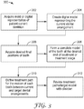
- FIG. 3 illustrates the general flow of an exemplary process 300 for defining and generating a treatment plan, including repositioning appliances for orthodontic treatment of a patient.
- the steps of the process can be implemented as computer program modules for execution on one or more computer systems.
- Systems and methods for generating a treatment plan can be found, for example, in U.S. Patent Nos. US 7,435,083 (Chisti et al. ), US 7,134,874 (Chisti et al. ), U.S. Patent Publication Nos. 2009/0286196 (Wen et al. ); 2010/0260405 (Cinader ) and U.S. Patent 9,259,295 (Christoff et al. ).
- a mold or a scan of patient's teeth or mouth tissue is acquired (Step 302). This generally involves taking casts of the patient's teeth and gums, and may in addition or alternately involve taking wax bites, direct contact scanning, x-ray imaging, tomographic imaging, sonographic imaging, and other techniques for obtaining information about the position and structure of the teeth, jaws, gums and other orthodontically relevant tissue.
- a digital data set is derived from this data that represents an initial (e.g., pretreatment) arrangement of the patient's teeth and other tissues.
- a computer model of the arch may then be re-constructed based on the scan data.
- a virtual dental model representing the patient's dental structure can be captured using a digital intraoral scan or by digitally scanning an impression or dental model.
- the digital images may be provided using a hand-held intra-oral scanner such as the intra-oral scanner using active wavefront sampling developed by Brontes Technologies, Inc. (Lexington, MA) and described, e.g., in PCT Publication No. WO 2007/084727 (Boerjes et al. ).
- other intra-oral scanners or intra-oral contact probes may be used.
- the digital structure data may be provided by scanning a negative impression of the patient's teeth.
- the digital structure data may be provided by imaging a positive physical model of the patient's teeth or by using a contact probe on a model of the patient's teeth.
- the model used for scanning may be made, for example, by casting an impression of a patient's dentition from a suitable impression material such as alginate or polyvinylsiloxane (PVS), pouring a casting material (such as orthodontic stone or epoxy resin) into the impression, and allowing the casting material to cure.
- a suitable scanning technique may be used for scanning the model, including X-ray radiography, laser scanning, computed tomography (CT), magnetic resonance imaging (MRI), and ultrasound imaging. Other possible scanning methods are described, e.g., in U.S. Patent Application Publication No. 2007/0031791 (Cinader, et al. ).
- the initial digital data set which may include both raw data from scanning operations and data representing surface models derived from the raw data, can be processed to segment the tissue constituents from each other (Step 304), including defining discrete dental objects. For example, data structures that digitally represent individual tooth crowns can be produced. In some embodiments, digital models of entire teeth are produced, including measured or extrapolated hidden surfaces and root structures.
- Desired final positions of the teeth, or tooth positions that are desired and/or intended end result of orthodontic treatment can be received, e.g., from a practitioner in the form of a descriptive prescription, can be calculated using basic orthodontic prescriptions, or can be extrapolated computationally from a clinical prescription (Step 306).
- the final position and surface geometry of each tooth can be specified (Step 308) to form a complete model of the teeth at the desired end of treatment or treatment stage.
- the result of this step is a set of digital data structures that represents a desired and/or orthodontically correct repositioning of the modeled teeth relative to presumed-stable tissue.
- the teeth and surrounding tissue can both be represented as digital data.
- Step 310 the process next defines a treatment path or tooth path for the motion of each tooth. This includes defining a plurality of planned successive tooth arrangements for moving teeth along a treatment path from an initial arrangement to a selected final arrangement.
- the tooth paths are optimized in the aggregate so that the teeth are moved in the most efficient and clinically acceptable fashion to bring the teeth from their initial positions to their desired final positions.
- a movement pathway for each tooth between a beginning position and a desired final position may be calculated based on a number of parameters, including the total distance of tooth movement, the difficulty in moving the teeth (e.g., based on the surrounding structures, the types and locations of teeth being moved, etc.) and other patient-specific data that may be provided.
- a user or a computer program may generate an appropriate number of intermediary steps (corresponding to a number of treatment steps).
- the user may specify a number of steps, and the software can map different appliance configurations accordingly.
- the movement pathway may be guided by (or set by) the user.
- the movement path may be divided up into multiple steps, where each step corresponds to a separate target arrangement.
- the predetermined amount is generally the amount that an appliance or appliance configuration can move a tooth in a particular direction in the time required for each treatment step.
- Each appliance configuration corresponds to a planned successive arrangement of the teeth, and represents a step along the treatment path for the patient.
- the steps can be defined and calculated so that each discrete position can follow by straight-line tooth movement or simple rotation from the tooth positions achieved by the preceding discrete step and so that the amount of repositioning required at each step involves an orthodontically optimal amount of force on the patient's dentition.
- this calculation step can include interactions with the practitioner (Step 312).
- the process can include interaction with a practitioner responsible for the treatment of the patient (Step 312).
- Practitioner interaction can be implemented using a client process programmed to receive tooth positions and models, as well as path information from a server computer or process in which other steps of process 300 are implemented.
- the treatment planning described with respect to FIG. 3 may be embodied within a computer-readable storage medium, such as a computer-readable storage medium of clinician's computing device and/or manufacturer's computer, or both.
- the computer-readable storage medium stores computer-executable instructions that, when executed, configure a processor to perform the model preparation and treatment planning techniques described above.
- a completed treatment plan for use in manufacturing the appliances of the present includes a plurality of successive arrangements between an initial arrangement and the desired final arrangement.
- the plurality of successive dental arrangements may be incorporated into a single appliance or apportioned between multiple appliances to be worn in series.
- a suitable treatment plan identifies a number of appliances in an acceptable series, as well as a target arrangement and a commencing arrangement for each appliance in the series.
- a plurality of planned, successive arrangements may be stored between the target and the commencing arrangements.
- the "target arrangement” may be a desired final dental arrangement or a planned successive dental arrangement the patient should reach after treatment with the appliance.
- the "commencing arrangement” is the dental arrangement the appliance is configured to represent when the appliance is first placed in the patient's mouth. As such, it is closest in orientation to the initial or current arrangement of the patient's teeth, and in some embodiments represents the current arrangement.
- Continuous memory appliances can be formed by incorporating a plurality of planned successive tooth arrangements into a single appliance structure. While typical appliances are formed in stages progressing from the patient's current arrangement to a target arrangement, the continuous memory appliances of the present disclosure are initially formed to approximate the target tooth arrangement. Additional shapes are added to the appliance in regressive fashion, working backward from the target arrangement to the commencing arrangement of the treatment plan. By manufacturing the appliances in this way, the patient or practitioner may unlock the next phase of treatment by triggering a change in the shape of the appliance from the commencing arrangement to the next successive arrangement until the target arrangement is reached.
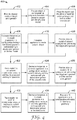
- a general process 400 for creating a continuous memory appliance is illustrated in FIG. 4 .
- One, some, or all of the steps of method 400 may be performed in a temperature and pressure controlled chamber.
- a physical, dental model of the patient's teeth in a target arrangement is provided (Step 402).
- a sheet of semicrystalline polymeric material is provided and placed over the dental model. (Step 404).
- the semicrystalline, polymeric material is substantially non-crosslinked.
- the model and the sheet of material are placed under a first pressure and heated to a first temperature near, but preferably below, the melt temperature of the polymer (Step 406).
- the combination of heat and pressure/or vacuum causes the material to soften.
- the model and sheet are maintained at the first temperature and pressure until such time as the sheet has conformed to the shape and orientation of the dental model and crystalline structures in the polymer have melted.
- the temperature is subsequently decreased (preferably isobarically) to create a shell appliance in a configuration having a first stored geometry corresponding to the dental arrangement of the first model (Step 408).
- the shell appliance is subsequently crosslinked, in presently preferred circumstances using ionizing radiation. (Step 410).
- the crosslinked shell in a configuration having the first stored geometry now represents the original shape of the appliance.
- the polymeric material is heated to a temperature above the upper range of its crystallization temperature and potentially above the T trans , for example, about 120°C, about 130°C, about 140°C, during the forming process of Step 406.
- the first temperature is below the melting temperature of the semicrystalline polymeric material, typically about 25°C below to about 0.5°C below.
- various temperatures and times may be utilized.
- the pressure applied is greater than 10kPa, e.g., greater than 50 kPa, 75 kPa, 100 kPa, 125 kPa, or greater than 150 kPa. In some embodiments, the pressure is maintained for greater than 30 seconds, e.g., greaterthan 45 seconds, 60 seconds, 2.5 minutes, 5.0 minutes, 10 minutes, 20 minutes, 30 minutes, 60 minutes, greater than 90 minutes, or even greater than 120 minutes, before release of pressure back to nominal atmospheric pressure. The pressure may be applied by direct force on the polymeric material and/or vacuum.
- a first plurality of crystalline structures are formed in the polymeric material as the temperature is reduced from first molding temperature to a subsequent temperature (e.g., room temperature) in step 408.
- the crystalline structures formed hold the appliance in the first stored geometry prior to irradiation or other suitable method of creating crosslinks in the polymeric material.
- the temperature is gradually reduced.
- appliance may be quenched by rapid reduction in temperature.
- the parameters selected remain consistent for each relevant step in the process.
- the rate of temperature reduction could be in the range of about 0.5°C to about 10°C per minute, but is typically held at the same rate within the range for each temperature reduction step in the process 400.
- Irradiation if used to crosslink the material, can be done at room temperature or at elevated temperatures typically below the first molding temperature. Irradiation can be performed in air, in vacuum, or in oxygen-free environment, including inert gases such as nitrogen or noble gases. Irradiation can be performed by using electron-beam, gamma irradiation, or x-ray irradiation. In some embodiments, an ionizing radiation (e.g., an electron beam, x-ray radiation or gamma radiation) is employed to crosslink the non-segmented, polymeric material. In specific embodiments, gamma radiation is employed to crosslink the substantially non-crosslinked polymeric material.
- an ionizing radiation e.g., an electron beam, x-ray radiation or gamma radiation
- gamma radiation is employed to crosslink the substantially non-crosslinked polymeric material.
- the irradiating (with any radiation source) is performed until the sample receives a dose of at least 0.25 Mrad (2.5 kGy), e.g., at least 1.0 Mrad (10 kGy), at least 2.5 Mrad (25 kGy), at least 5.0 Mrad (50 kGy), or at least 10.0 Mrad (100 kGy). In some embodiments, the irradiating is performed until the sample receives a dose of between 1.0 Mrad and 6.0 Mrad, e.g., between 1.5 Mrad and 4.0 Mrad.
- the appliance is treated to create chemical crosslinks using methods known in the art.
- peroxides can be added to the polymer, and the polymer can be maintained at an elevated temperature after forming into the first stored geometry to allow the peroxides to react.
- silanes can be grafted to a polymer backbone, such as polyethylene, and the polymer can be crosslinked upon exposure to a hot, humid environment.
- the thickness of the semicrystalline polymer sheet is chosen to provide a clinically appropriate thickness of the material in the resultant appliance.
- the thickness of the material should typically be selected such that the memory appliance is stiff enough to apply sufficient force to the teeth, but remains thin enough to be comfortably worn.
- the thickness of the walls of the appliance may be between 0.05 mm and 2 mm, or between 0.1 mm and 1 mm.
- a second physical, dental model of the patient's teeth in a least one successive arrangement from the patient's treatment plan is provided (Step 420).
- the second arrangement includes a least one tooth in a different position or orientation than the same tooth in the first model.
- the second dental model is a second storable geometry representing an arrangement of the patient's teeth between the initial arrangement and the first arrangement, and includes teeth in positions or orientations between the target arrangement and initial arrangement. Starting from the initial arrangement of the patient's teeth, the second dental model actually precedes the first dental model in that the patient's teeth, during treatment with the appliance, will reach the second arrangement prior to arriving at the first arrangement.
- the appliance still reflecting the first model arrangement, is secured on the second dental model, and the model and the appliance are placed under pressure and heated to a second molding temperature (Step 422).
- the model and appliance are maintained at the second molding temperature and pressure for a period of time.
- the temperature is decreased (preferably isobarically) to create an appliance having a second stored geometry corresponding generally to the dental arrangement represented by the second model (Step 424).
- the second molding temperature is selected so that the appropriate number of these crystallites are destroyed.
- the second molding temperature can be the same or different (i.e., cooler or hotter) than the first molding temperature.
- the second molding temperature is cooler than the first molding temperature.
- the second molding temperature is at least 1, at least 2, at least 3, at least 4, at least 5°C less than the first molding temperature.
- the second molding temperature is no more than 10, no more than 5, and no more than 2°C warmer than the first molding temperature.
- the second molding temperature is between 100 and 120°C.
- a second plurality of crystalline structures are formed in the polymeric material as the temperature is reduced from second molding temperature to a subsequent temperature (e.g., room temperature).
- the crystalline structures formed hold the appliance in the second stored geometry.
- a third stored geometry is created in the appliance.
- a third physical, dental model of the patient's teeth in a preceding successive arrangement from the patient's treatment plan is provided (Step 430).
- the third arrangement includes a least one tooth in a different position or orientation than the same tooth in the second model.
- the third dental model provides a third storable geometry representing an arrangement of the patient's teeth between the initial arrangement and the second arrangement.
- the third dental model actually precedes the second dental model in that the patient's teeth, during treatment with the appliance, will reach the third arrangement prior to arriving at the second arrangement.
- the appliance now reflecting the second model arrangement, is secured on the third dental model, and the model and the appliance are placed under pressure and heated to a third molding temperature cooler than the second molding temperature (Step 432).
- the model and appliance are maintained at the third molding temperature and pressure for a period of time.
- the temperature is decreased (preferably isobarically) to room temperature to create an appliance having a third stored geometry corresponding to the shapes and orientations of teeth in the third dental model (Step 434).
- the third molding temperature is at least 4, at least 6, at least 7, at least 8, at least 9, and at least 10°C, at least 15°C less than the second molding temperature. In certain embodiments, the third molding temperature is between 90 and 100°C.
- a third plurality of crystallites are formed in the polymeric material as the temperature is reduced from third molding temperature to a subsequent temperature (e.g., room temperature). The crystalline structures formed hold the appliance in the third stored geometry until triggered according to methods discussed below.
- An insufficiently large gap in second and third molding temperatures can have two consequences for continuous memory appliances: 1) a user or practitioner may inadvertently transition the appliance to a subsequent geometry by heating above the requisite molding temperature and 2) the desired arrangement may not be adequately stored in the appliance, as an adequate portion of crystallites are not retained during the corresponding formation.
- the molding process may be finished (Step 440). If not, the process 400 of storing geometries corresponding to different dental arrangements in an appliance can be repeated as many times as desired until the commencing arrangement is stored in the appliance.
- the appliance can be manufactured to store at least 4, at least 6, at least 10, at least 20, and at least 30 distinct appliance geometries.
- Dental models representing the target and successive dental arrangements can be fabricated by manually forming, sectioning, and re-assembling a physical dental casting. If the target dental arrangement is defined as an intermediate or final arrangement, then this casting may be sectioned into individual model tooth elements, and the tooth elements can be rearranged to form the desired dental arrangement. Further, the tooth elements can be waxed back together to provide the dental model.
- a final dental arrangement can be determined using a computer algorithm or input from a treating professional in a treatment plan as described above, and one or more intermediate dental arrangements derived by sub-dividing the treatment into a series of discrete steps can be created.
- one or more of the dental arrangements can include a reduced image as is described, e.g., in U.S. Patent Publication No. 2010/0260405 (Cinader ).
- respective dental models may be directly fabricated using rapid prototyping methods.
- Examples of rapid prototyping techniques include, but are not limited to, three-dimensional (3D) printing, selective area laser deposition or selective laser sintering (SLS), electrophoretic deposition, robocasting, fused deposition modeling (FDM), laminated object manufacturing (LOM), stereolithography (SLA) and photostereolithography.
- SLS selective area laser deposition or selective laser sintering
- FDM fused deposition modeling
- LOM laminated object manufacturing
- SLA stereolithography
- photostereolithography photostereolithography
- the dental model can also be a reconfigurable dental model, thereby allowing individual teeth models to be rearranged without sectioning.
- reconfigurable dental models are described, e.g., in U.S. Patent Nos. 6,227,851 (Chishti et al. ), 6,394,801 (Chishti et al. ), and 9,259,295 (Christoff et al. ).
- the reconfigurable dental model may be manually controlled (e.g., relying on a technician or other user to reposition individual teeth) or computer controlled.
- Use of a computer controlled reconfigurable dental model can be particularly advantageous in certain circumstances, as the individual teeth can be moved at a deliberate rate during the forming process as described in more detail below.
- a single dental model system is manipulated and reconfigured to model different tooth configurations by controlling the movement of at least some of the individual tooth members, or groups of members, with manipulation mechanisms.
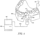
- FIG. 5 a simplified illustration of such a reconfigurable dental mold 500 for the fabrication of dental appliances is shown.
- the mold 500 is a positive representation of the tooth configuration and dental arch of the lower jaw.
- the tooth configuration is created by the placement and alignment of tooth members 501.
- the individual tooth members 501 are typically produced to resemble the individual shape of each of the patient's teeth.
- the tooth members 501 are supported by a frame 502, which can house manipulation mechanisms for controlling the position and orientation of the tooth members within the arch.
- the tooth members 501 and frame 502 of the dental model system may be produced manually or with the use of digital imaging and computer controlled molding systems.
- the frame houses one or more manipulation devices 511 which manipulate the tooth members 501. Once coupled to the manipulation devices 511, the tooth members 501 can be actuated and repositioned.
- the manipulation device 511 can be a single mechanism, linked simultaneously to each individual tooth member 501 or group of members using, for example, a series of mechanical linkages.
- the tooth members 501 can be actuated by a combination of manipulation devices each providing some degree of manipulation within a given coordinate system.
- the manipulation devices 511 which create the actual six degree of freedom movement of the tooth members 501, may be controlled manually and/or with the use of a microprocessor.
- the repositioning of the individual tooth members 501 involves at least some of the components of manipulation device 511 being manually operated.
- the practitioner will manually actuate each control mechanism, usually with finger pressure, which will in turn actuate the inner components of the manipulation device until a desired tooth arrangement is produced.
- manual operation may be assisted with the visual aide of computer graphics or with instructions provided by software code.
- manipulation of manipulation devices 511 can be performed using a computer 600 or a workstation having a suitable graphical user interface (GUI) 601.
- GUI graphical user interface
- computer 600 is electrically coupled to manipulation device 511 to enable computer generated instructions to be sent to manipulation devices 511 via appropriate computer coupling methods, represented as line 602.
- the manipulation of tooth members 501 is driven using software appropriate for viewing and modifying the images (see above) on the GUI 601, as well as directing and controlling the tooth movements according to the treatment plan.
- the mold 500 may be manipulated through a series of tooth configurations representing a planned successive arrangement and a corresponding stage in orthodontic treatment.
- the initial tooth configuration is represented by digital information and is introduced to computer 600 for manipulation of the mold 500.
- the final tooth arrangement is incorporated into a final digital data set.
- a plurality of intermediate, successive digital data sets are generated to correspond to successive intermediate tooth arrangements and stored in medium accessible to computer 600.
- the user of the reconfigurable mold may then direct the software to send an instruction to a manipulation device 611 to direct a tooth member 601 to move to a position which corresponds to a position digitally represented in a planned successive data set or target data set.
- the dental model system can be used to fabricate the continuous memory appliance.
- the dental models are provided in discrete stages.
- the appliance may be removed from the corresponding dental model after each cooling step.
- the dental model of arrangement (n) is then replaced with a distinct dental model of a preceding intermediate arrangement of the treatment plan (n-1), or the tooth members in a reconfigurable dental model are manipulated and arranged to correspond to the preceding, planned successive arrangement (n-1).
- the appliance is placed over the new arrangement and a new plurality of crystallites are formed.
- the appliance structure is kept in contact with a reconfigurable dental mold throughout the duration of the process for storing treatment geometries, as set out as process 700 in Fig. 6 .
- the polymeric material is kept under pressure as the dental mold is reconfigured to each desired dental arrangement.
- the appliance is first configured to represent the target arrangement and crosslinked to set the original shape before storing the desired series of successive arrangements (Step 702). This initial configuration can be done on the reconfigurable dental mold or a static mold (e.g., as used in process 400 above).
- a reconfigurable dental mold of a planned preceding arrangement (a second arrangement relative to the original shape) is provided (Step 704).
- the reconfigurable model in the second arrangement and the crosslinked appliance in the original shape are placed under pressure and heated to a first molding temperature (Step 706).
- the model and appliance are maintained at the first temperature until such time as the sheet has conformed to the shape and orientation of the dental model in the second arrangement (Step 708).
- the temperature is decreased (preferably isobarically) to a second molding temperature (Step 710).
- the mold is then reconfigured to a planned preceding arrangement (a third arrangement), causing a deformation of the crosslinked appliance (Step 712).
- a processor operating suitable software sends instructions or otherwise directs the individual teeth of the reconfigurable mold to move to the relevant arrangement.
- the movement may be prompted by a user operating a computer or be programmed to occur at least semiautomatically.
- the mold and appliance are maintained at the second temperature until such time as the sheet has conformed to the shape and orientation of the dental mold in the third arrangement, creating an appliance in a configuration having a third stored geometry corresponding to the third arrangement (Step 714).
- the appliance structure and reconfigurable dental mold are maintained in each planned arrangement at the requisite molding temperature for a period of time sufficient to allow for a steady state of crystallization. This period may be dependent on the polymeric material in the appliance and the first molding temperature.
- the pressure is decreased subsequently to the rearrangement of the dental mold, or at slower rate than the movement of individual tooth members of the mold in reaching the second arrangement.
- the tooth members in the reconfigurable mold can be moved between arrangements at any desired rate (e.g., 0.5 mm/min), so long as the velocity does not irreversibly degrade the polymeric material.
- the process 700 is repeated until the appliance has a configuration representing the desired commencing arrangement and has stored all planned successive arrangements between the commencing arrangement and the target arrangement (Step 716).
- the method of manufacturing 700 allows the appliance to accommodate the entire movement path of each tooth moved between the commencing arrangement and the target arrangement.
- Accommodation of the full path of movement can, in certain circumstances, ensure the force applied to reposition the tooth remains relatively constant between stages, even as the appliance deforms while worn on the patient's dental arch.
- the use of a single mold with continuous movement reduces manufacturing time and cost, as individual models representing each planned successive arrangement do not have to be created and swapped out at each storage stage.
- a complete sequence of appliances can be made using only a sufficient amount of polymeric material to form a single tray.
- the reconfigurable dental mold can also be reused during the course of treatment if the orthodontic practitioner determines that one or more additional intermediate appliances would be best for additional treatment.
- Appliances may also be fabricated with special features requested by the practitioner, such as buttons and windows to assist certain teeth movement.
- buttons and windows may be used to help secure the appliances to the patient's dental arch, and may be used to direct force to move the teeth of the dental arch.
- small buttons can be installed on the model teeth in the manufacturing process.
- a template plastics tray will be made to assist the doctors to place the buttons in a subject's teeth.
- Appliances can then be fabricated with windows (e.g., small cut-outs) at the location of each prescribed button.
- windows e.g., small cut-outs
- the elastic recovery force of the shape memory material can be designed to be sufficient to deform the other material at the temperatures of interest, and the relative thicknesses of the two layers can be chosen achieve this balance.
- the second, non-memory layer can have a transition temperature between use temperature and the transition temperature range of the shape memory polymer to allow it to be deformed by the shape memory material. Suitable methods for design and manufacture of multilayer shell appliances can be found, for example, in US Patent No. 8,758,009 (Chen et al. ).
- Manufacturing may include post-processing to remove uncured resin and remove support structures, or to assemble various components, which may also be necessary and could also be performed in a clinical setting.
- a method of treatment 800 using an appliance (particularly a shell appliance) of the present disclosure is depicted.
- An adjustment appliance having an original shape and at least three stored successive geometries is provided to the patient in the commencing arrangement (Step 802). It should be appreciated that an appliance could be provided having 2 or fewer stored geometries in addition to the original shape, and such embodiments may include one less heating and wear step. Similarly, an adjustment appliance may be provided with more, even considerably more, than three or four stored geometries, in which case the treatment process may include additional heating and wear steps commensurate with the number of stored geometries.
- the patient (or practitioner) first places the appliance on his or her dental arch and the appliance is worn for prescribed period of time to define a first wear period (Step 804).
- the patient (or practitioner) removes the appliance from the mouth and heats appliance to a temperature above the molding temperature used to create the commencing arrangement in the appliance (Step 806).
- the heating destroys a portion of the formed crystal structures to unlock or transition to a second stored appliance geometry representing a successive intermediate arrangement in the patient's treatment plan.
- the appliance is then cooled, typically back to room temperature.
- the appliance is heated to no greater than 6°C above the corresponding molding temperature, in some embodiment no greater than 5, in some embodiments no greater than 3, and in some embodiments not greater than 1°C above the corresponding molding temperature. In certain typical implementations, the appliance is heated to a temperature of 80°C to 95°C to transition to the second stored geometry.
- Patient (or practitioner) subsequently places the appliance, now representing the second geometry, on the dental arch and wears the shell for a prescribed period of time (Step 808).
- the patient (or practitioner) again heats the appliance to a temperature above the molding temperature used to form the appliance in the first successive intermediate arrangement (i.e., the second stored geometry) (Step 810).
- the heating destroys an additional portion of the formed crystal structures to unlock or otherwise transition to a third stored appliance geometry representing a successive intermediate arrangement in the patient's treatment plan.
- the appliance is heated to a temperature of 95°C to 110°C to transition to the third stored geometry.
- the patient (or practitioner) subsequently places the appliance, now representing the third geometry, on the dental arch and wears the shell for prescribed period of time (Step 812).
- the patient (or practitioner) again heats appliance to a temperature above the molding temperature used to form the appliance in the second successive intermediate arrangement (i.e., the third stored geometry) (Step 814).
- the heating destroys an additional portion of the formed crystal structures to unlock or otherwise transition to a fourth stored appliance geometry representing the original shape.
- the appliance is heated to a temperature of 110°C to 120°C to transition to the original shape.
- Each stored geometry in the appliance can be recovered using heat sources such as a hot air gun, hot plate, steam, conventional oven, infrared heater, radiofrequency (R f) sources or microwave sources.
- the appliance can be immersed in a heated bath containing a suitable inert liquid (for example, water or a fluorochemical fluid) that will not dissolve or swell the appliance in either its cool or warm states.
- a suitable inert liquid for example, water or a fluorochemical fluid
- the appliance can be encased in a plastic pouch or other container which is in turn heated (e.g., electrically), or subjected to one or more of the above-mentioned heating methods.
- the appliance is preferably cooled to body temperature (37°C) or below to lock in the intended configuration and to avoid discomfort or injury.
- the patient After wearing the appliance having the fourth stored geometry for a prescribed period of time (Step 816), the patient may return to the practitioner who may evaluate the result of the first iteration of treatment (Step 818). In the event that the first iteration of treatment has resulted in satisfactory final placement of the patient's teeth, the treatment may be ended. However, if the first iteration of treatment did not complete the desired movement of the patient's teeth, one or more additional iterations of treatment may be performed. To begin the next iteration of treatment, the practitioner may taking another scan of the patient's teeth are taken to facilitate the design of the ordered set of removable dental appliances.
- evaluation of the result of the first iteration of treatment may include taking another scan of the patient's teeth, in which case beginning the next iteration of treatment may simply involve forwarding the digital model of the patients teeth to a manufacturing facility so that another adjustment appliance or series of adjustment appliance may be manufactured for the patient based on the new positions of the patient's teeth.
- the newly acquired scan may be used to create one or more iterations of adjustment appliances in the practitioner's facility.
- second, third, or more intermediate scans of the teeth can be performed using any suitable technique or combination of techniques.
- the practitioner or manufacturer can then utilize these intermediate scans to provide one or more additional appliances that are adapted to provide one or more corrective forces to the teeth such that one or more teeth are repositioned to either a subsequent intermediate arrangement or a final target arrangement.
- Any suitable technique or combination of techniques can be utilized to provide these intermediate scans, models, and arch members, e.g., the techniques described in U.S. Patent Application Publication No. 2010/0260405 (Cinader ) and International Publication WO2016/109660 (Raby et al. ).
- Various techniques of this disclosure may be implemented in a wide variety of computer devices, such as servers (including the Cloud), laptop computers, desktop computers, notebook computers, tablet computers, hand-held computers, smart phones, and the like. Any components, modules or units have been described to emphasize functional aspects and does not necessarily require realization by different hardware units.
- the techniques described herein may also be implemented in hardware, software, firmware, or any combination thereof. Any features described as modules, units or components may be implemented together in an integrated logic device or separately as discrete but interoperable logic devices. In some cases, various features may be implemented as an integrated circuit device, such as an integrated circuit chip or chipset.
- modules have been described throughout this description, many of which perform unique functions, all the functions of all of the modules may be combined into a single module, or even split into further additional modules.
- the modules described herein are only exemplary and have been described as such for better ease of understanding.
- the techniques may be realized at least in part by a non-transitory computer-readable medium comprising instructions that, when executed in a processor, performs one or more of the methods described above.
- the computer-readable medium may comprise a tangible computer-readable storage medium and may form part of a computer program product, which may include packaging materials.
- the computer-readable storage medium may comprise random access memory (RAM) such as synchronous dynamic random access memory (SDRAM), read-only memory (ROM), non-volatile random access memory (NVRAM), electrically erasable programmable read-only memory (EEPROM), FLASH memory, magnetic or optical data storage media, and the like.
- RAM random access memory
- SDRAM synchronous dynamic random access memory
- ROM read-only memory
- NVRAM non-volatile random access memory
- EEPROM electrically erasable programmable read-only memory
- FLASH memory magnetic or optical data storage media, and the like.
- the computer-readable storage medium may also comprise a non-volatile storage device, such as a hard-disk, magnetic tape, a compact disk (CD), digital versatile disk (DVD), Blu-ray disk, holographic data storage media, or other non-volatile storage device.
- a non-volatile storage device such as a hard-disk, magnetic tape, a compact disk (CD), digital versatile disk (DVD), Blu-ray disk, holographic data storage media, or other non-volatile storage device.
- the term "processor,” as used herein may refer to any of the foregoing structure or any other structure suitable for implementation of the techniques described herein.
- the functionality described herein may be provided within dedicated software modules or hardware modules configured for performing the techniques of this disclosure. Even if implemented in software, the techniques may use hardware such as a processor to execute the software, and a memory to store the software. In any such cases, the computers described herein may define a specific machine that is capable of executing the specific functions described herein. Also, the techniques could be
Landscapes
- Health & Medical Sciences (AREA)
- Life Sciences & Earth Sciences (AREA)
- General Health & Medical Sciences (AREA)
- Oral & Maxillofacial Surgery (AREA)
- Dentistry (AREA)
- Epidemiology (AREA)
- Veterinary Medicine (AREA)
- Animal Behavior & Ethology (AREA)
- Public Health (AREA)
- Engineering & Computer Science (AREA)
- Mechanical Engineering (AREA)
- General Engineering & Computer Science (AREA)
- Physics & Mathematics (AREA)
- Optics & Photonics (AREA)
- Dental Tools And Instruments Or Auxiliary Dental Instruments (AREA)
Claims (15)
- Appareil dentaire à coque polymère (100) destiné à être placé sur une arcade dentaire, comprenant
un creux concave ayant une cavité configurée pour être positionnée sur une pluralité de dents dans l'arcade dentaire et ayant une première forme approximative, dans lequel le creux concave comprend un polymère à mémoire de forme réticulé, et dans lequel le polymère à mémoire de forme réticulé est un polymère semi-cristallin, non segmenté, configuré pour restituer au creux concave(a) une deuxième forme approximative lors de l'application d'un premier stimulus d'énergie externe ; et
caractérisé en ce que(b) une troisième forme approximative est restituée lors de l'application d'un deuxième stimulus d'énergie externe d'une amplitude supérieure à celle du premier stimulus d'énergie. - Appareil dentaire à coque polymère selon la revendication 1, dans lequel la troisième forme approximative représente un agencement final prescrit des dents dans l'arcade dentaire.
- Appareil dentaire à coque polymère selon la revendication 1, dans lequel la deuxième forme approximative représente un agencement intermédiaire des dents dans l'arcade dentaire.
- Appareil dentaire à coque polymère selon la revendication 1, dans lequel chaque stimulus d'énergie externe est une augmentation de la température.
- Appareil dentaire à coque polymère selon la revendication 4, dans lequel chaque stimulus d'énergie externe représente une température de transition, et dans lequel chaque température de transition est supérieure à 37 °C.
- Appareil dentaire à coque polymère selon la revendication 1, dans lequel le polymère à mémoire de forme réticulé est en outre configuré pour restituer au creux concave une quatrième forme approximative lors de l'application d'un troisième stimulus d'énergie externe d'une amplitude supérieure aux premier ou deuxième stimuli d'énergie.
- Coque polymère selon la revendication 1, dans laquelle le polymère contient des réticulations chimiques.
- Appareil à coque polymère selon la revendication 1, dans lequel le matériau polymère semi-cristallin comprend un certain nombre de structures cristallines, et dans lequel une partie des structures cristallines est interrompue de manière irréversible lors de l'application du premier stimulus d'énergie externe pour faire passer la coque à la deuxième forme approximative.
- Appareil à coque polymère selon la revendication 8, dans lequel la partie restante de structures cristallines est interrompue de manière irréversible lors de l'application du troisième stimulus d'énergie externe.
- Appareil à coque polymère selon la revendication 1, dans lequel le polymère comprend une plage de températures de cristallisation, et dans lequel la récupération des deuxième et troisième formes approximatives se produit lorsque la température de la coque est augmentée jusqu'à une température correspondante dans la plage de températures de cristallisation.
- Procédé de fabrication d'appareils dentaires à coque polymère, configurés pour se conformer à une ou plusieurs dents d'un patient, le procédé comprenant :la fourniture d'un premier modèle positif (402) de la dentition du patient, le modèle représentant un agencement repositionné des dents du patient ;le moulage (406, 408) sur le modèle à une première température de moulage d'une feuille de matériau polymère cristallisable réticulable ayant une plage de températures de cristallisation ayant une limite supérieure et une limite inférieure ;la réticulation (410) du polymère pour créer un appareil ayant une première géométrie enregistrée ;la fourniture d'un deuxième modèle (420) représentant un premier agencement intermédiaire des dents du patient, l'agencement comprenant une ou plusieurs dents dans des orientations différentes par rapport au premier modèle ;le fait de soumettre (422, 424) l'appareil à une deuxième température de moulage au sein de la plage de températures de cristallisation et qui est inférieure à la première température de moulage pour créer une coque ayant une deuxième géométrie enregistrée ;la fourniture d'un troisième modèle (430) représentant un deuxième agencement intermédiaire des dents du patient, le deuxième agencement comprenant une ou plusieurs dents dans des orientations différentes par rapport au premier agencement intermédiaire ;le fait de soumettre (432) l'appareil à une troisième température de moulage au sein de la plage de températures de cristallisation pour créer une troisième géométrie enregistrée, la troisième température de moulage étant inférieure à la première ou à la deuxième température de moulage ; etle refroidissement (434) de la coque en dessous de la limite inférieure de la plage de températures de transition.
- Procédé selon la revendication 11, dans lequel le chauffage de la feuille comprend le chauffage pendant une période de temps suffisante pour faire fondre sélectivement au moins une partie des structures cristallines dans le matériau à mémoire de forme.
- Procédé selon la revendication 11, dans lequel le premier modèle comprend une pluralité de modèles de dents reconfigurables agencés par rapport à une arcade physique, et dans lequel la fourniture du deuxième modèle comprend le déplacement d'au moins un des objets dent pour créer le deuxième agencement.
- Procédé selon la revendication 13, dans lequel le moulage d'une feuille de matériau polymère réticulable sur le modèle comprend l'action d'appliquer une pression sur le modèle, et dans lequel le modèle de dent est déplacé le long d'un segment de chemin de traitement pendant que la pression est appliquée au modèle.
- Procédé selon la revendication 11, dans lequel le matériau polymère forme un nombre croissant de structures cristallines lorsque la température est réduite de la limite supérieure de la plage de températures de cristallisation à la limite inférieure.
Applications Claiming Priority (2)
| Application Number | Priority Date | Filing Date | Title |
|---|---|---|---|
| US201562249749P | 2015-11-02 | 2015-11-02 | |
| PCT/US2016/059909 WO2017079157A1 (fr) | 2015-11-02 | 2016-11-01 | Appareil orthodontique à mémoire de forme continue |
Publications (3)
| Publication Number | Publication Date |
|---|---|
| EP3370638A1 EP3370638A1 (fr) | 2018-09-12 |
| EP3370638A4 EP3370638A4 (fr) | 2019-06-19 |
| EP3370638B1 true EP3370638B1 (fr) | 2020-08-19 |
Family
ID=58662667
Family Applications (1)
| Application Number | Title | Priority Date | Filing Date |
|---|---|---|---|
| EP16862796.6A Active EP3370638B1 (fr) | 2015-11-02 | 2016-11-01 | Appareil orthodontique à mémoire de forme continue |
Country Status (6)
| Country | Link |
|---|---|
| US (2) | US20180250099A1 (fr) |
| EP (1) | EP3370638B1 (fr) |
| JP (1) | JP6417076B1 (fr) |
| CN (1) | CN108348306B (fr) |
| BR (1) | BR112018008915A2 (fr) |
| WO (1) | WO2017079157A1 (fr) |
Cited By (1)
| Publication number | Priority date | Publication date | Assignee | Title |
|---|---|---|---|---|
| DE102020214587A1 (de) | 2020-11-19 | 2022-05-19 | Dirk Wiechmann | Verfahren zum Programmieren eines kieferorthopädischen Bauteils aus einem Formgedächtnismaterial |
Families Citing this family (32)
| Publication number | Priority date | Publication date | Assignee | Title |
|---|---|---|---|---|
| ES2874777T3 (es) | 2012-10-30 | 2021-11-05 | Univ Southern California | Aparato de ortodoncia con arco de alambre encajado a presión, antideslizante |
| US10874485B2 (en) * | 2016-02-24 | 2020-12-29 | 3Shape A/S | Comparing a current dental setup with a series of preset dental setups |
| CN117695035A (zh) | 2016-04-18 | 2024-03-15 | 斯威夫特健康系统有限公司 | 具有非滑动的绑扎弓丝的牙齿正畸矫正器 |
| FR3051352B1 (fr) * | 2016-05-18 | 2021-08-27 | D & D | Ruban a memoire de forme |
| CN115024842B (zh) | 2017-01-31 | 2025-01-28 | 斯威夫特健康系统有限公司 | 混合正畸弓丝 |
| CN110740704B (zh) | 2017-04-21 | 2021-10-29 | 斯威夫特健康系统有限公司 | 间接粘接托盘、非滑动正畸矫正器和使用其的配准系统 |
| DE102017009287B4 (de) | 2017-10-06 | 2019-07-11 | Fraunhofer-Gesellschaft zur Förderung der angewandten Forschung e.V. | Kieferorthopädisches Zahnregulierungsmittel und Verfahren zu seiner Herstellung |
| GB201802402D0 (en) * | 2018-02-14 | 2018-03-28 | Littlejohn Alexander | Apparatus and method for prosthodontics |
| US20200275996A1 (en) | 2019-03-01 | 2020-09-03 | Swift Health Systems Inc. | Indirect bonding trays with bite turbo and orthodontic auxiliary integration |
| DE102019109807A1 (de) * | 2019-04-12 | 2020-10-15 | K Line Europe Gmbh | Verfahren zum wiederholten Aktivieren einer kieferorthopädischen Korrekturvorrichtung |
| CN110123467A (zh) * | 2019-05-21 | 2019-08-16 | 尤美医疗科技(大连)有限公司 | 具有形状记忆功能的齿科正畸隐形牙套及其使用方法 |
| DE102019114593B4 (de) * | 2019-05-30 | 2022-08-04 | K Line Europe Gmbh | Verfahren und Satz von Korrekturvorrichtungen zum Durchführen einer kieferorthopädischen Maßnahme |
| DE102019124364B4 (de) * | 2019-09-11 | 2021-11-18 | K Line Europe Gmbh | Verfahren und Steuereinheit zum Berechnen eines Stimulus für die Formänderung eines medizinischen Hilfsmittels |
| CN114727853B (zh) | 2019-10-31 | 2024-10-01 | 斯威夫特健康系统有限公司 | 间接正畸粘合系统和方法 |
| EP4082475A4 (fr) * | 2019-12-23 | 2024-02-07 | Ortho Solutions, LC dba Dynaflex | Embout buccal et son procédé de fabrication |
| EP3888585B1 (fr) * | 2020-03-30 | 2022-11-23 | DENTSPLY SIRONA Inc. | Outil à main de séparation d'un appareil dentaire d'écartement de mâchoire à emboutissage profond de film thermoformé et procédé d'utilisation |
| US11273013B2 (en) | 2020-05-05 | 2022-03-15 | Ortho Solutions, LC | Twist-lock orthodontic post |
| CN116075279A (zh) | 2020-06-11 | 2023-05-05 | 斯威夫特健康系统公司 | 具有非滑动弓形件的正畸矫正器 |
| JP7742371B2 (ja) | 2020-06-30 | 2025-09-19 | ソルベンタム インテレクチュアル プロパティズ カンパニー | 歯再配置システム |
| US20220241054A1 (en) * | 2021-02-02 | 2022-08-04 | Jeffrey Seymour | Orthodontic appliance |
| US12268571B2 (en) | 2021-03-12 | 2025-04-08 | Swift Health Systems Inc. | Indirect orthodontic bonding systems and methods |
| CN117412727A (zh) * | 2021-06-01 | 2024-01-16 | 阿莱恩技术有限公司 | 使用三维控件对治疗计划的临床修改的自动化管理 |
| WO2023033870A1 (fr) | 2021-09-03 | 2023-03-09 | Swift Health Systems Inc. | Procédé d'administration d'adhésif pour collage de verrous orthodontiques |
| US12193908B2 (en) | 2021-09-03 | 2025-01-14 | Swift Health Systems, Inc. | Orthodontic appliance with non-sliding archform |
| JP7202729B1 (ja) | 2021-10-18 | 2023-01-12 | 株式会社Oh my teeth | 歯列矯正アドバイスシステム、歯列矯正アドバイス方法およびそのプログラム |
| USD1043994S1 (en) | 2022-01-06 | 2024-09-24 | Swift Health Systems Inc. | Archwire |
| CN114681077A (zh) * | 2022-03-04 | 2022-07-01 | 杭州隐捷适生物科技有限公司 | 基于形状记忆材料的双稳态隐形矫治方法及矫治器 |
| CN115204001B (zh) * | 2022-06-08 | 2026-04-14 | 北京大学口腔医学院 | 无托槽隐形矫治器模型的设计、验证分析、优化方法 |
| DE102022125583A1 (de) | 2022-10-05 | 2024-04-11 | Fraunhofer-Gesellschaft zur Förderung der angewandten Forschung eingetragener Verein | Kieferorthopädisches Zahnregulierungsmittel aus Formgedächtnispolymeren und Verfahren zu seiner Herstellung |
| KR102624482B1 (ko) * | 2022-11-10 | 2024-01-16 | 주식회사 월드바이오텍 | 비트리머 기반 형상 기억 고분자 및 이를 이용한 치아 교정 장치 |
| EP4509091A1 (fr) * | 2023-08-17 | 2025-02-19 | K Line Europe GmbH | Procédé de fabrication d'un aligneur dentaire et ligne de fabrication associée |
| EP4623858A1 (fr) * | 2024-03-28 | 2025-10-01 | K Line Europe GmbH | Procédé et appareil pour conférer au moins une forme alternative à un aligneur orthodontique |
Family Cites Families (57)
| Publication number | Priority date | Publication date | Assignee | Title |
|---|---|---|---|---|
| JPS6311148A (ja) * | 1986-07-01 | 1988-01-18 | 大作 武彦 | 歯列矯正具 |
| JPH039712U (fr) * | 1989-06-20 | 1991-01-30 | ||
| JP2863100B2 (ja) * | 1993-12-07 | 1999-03-03 | チカミミルテック株式会社 | 歯列保定装置およびその製法 |
| AU744385B2 (en) | 1997-06-20 | 2002-02-21 | Align Technology, Inc. | Method and system for incrementally moving teeth |
| US6183248B1 (en) | 1998-11-30 | 2001-02-06 | Muhammad Chishti | System and method for releasing tooth positioning appliances |
| US5975893A (en) | 1997-06-20 | 1999-11-02 | Align Technology, Inc. | Method and system for incrementally moving teeth |
| US6450807B1 (en) | 1997-06-20 | 2002-09-17 | Align Technology, Inc. | System and method for positioning teeth |
| JP3732404B2 (ja) | 1998-02-23 | 2006-01-05 | ニーモサイエンス ゲーエムベーハー | 形状記憶ポリマー組成物、形状記憶製品を形成する方法、および形状を記憶する組成物を形成する方法 |
| WO2000019929A1 (fr) | 1998-10-08 | 2000-04-13 | Align Technology, Inc. | Developpement informatique automatise d'un plan de traitement orthodontique et d'un appareil prevu a cet effet |
| AU2164100A (en) * | 1998-12-04 | 2000-06-26 | Align Technology, Inc. | Reconfigurable dental model system for fabrication of dental appliances |
| US7404403B2 (en) * | 1998-12-16 | 2008-07-29 | Christopher John Farrell | Oral appliance |
| US6318994B1 (en) * | 1999-05-13 | 2001-11-20 | Align Technology, Inc | Tooth path treatment plan |
| US7092784B1 (en) | 2000-07-28 | 2006-08-15 | Align Technology | Systems and methods for forming an object |
| AU2002243678B2 (en) | 2001-01-24 | 2006-03-30 | Johnson & Johnson Vision Care, Inc. | Shape memory styrene copolymer |
| WO2003003935A1 (fr) * | 2001-07-02 | 2003-01-16 | Young-Kyu Choi | Appareil orthodontique a base de polymere a memoire de forme |
| US6739870B2 (en) | 2001-09-26 | 2004-05-25 | 3M Innovative Properties Company | Use of finite element analysis for orthodontic mechanics and appliance selection |
| JP4159035B2 (ja) | 2003-03-14 | 2008-10-01 | ニチアス株式会社 | 感熱膨張材及びその製造方法 |
| DE10349047B3 (de) * | 2003-10-17 | 2005-02-24 | Kettenbach Gmbh & Co. Kg | Verfahren und Abdrucklöffel zur Herstellung einer Dentalschiene |
| EP3111895B1 (fr) | 2004-02-03 | 2019-09-04 | The General Hospital Corporation | Polyethylene reticule hautement cristallin resistant a l'oxydation |
| US8194067B2 (en) | 2004-02-04 | 2012-06-05 | 3M Innovative Properties Company | Planar guides to visually aid orthodontic appliance placement within a three-dimensional (3D) environment |
| US7895917B2 (en) * | 2004-06-04 | 2011-03-01 | Gm Global Technology Operations, Inc. | Conformal grasp handle |
| US7563388B2 (en) * | 2004-08-27 | 2009-07-21 | The University Of Connecticut | Crosslinked liquid crystalline polymer, method for the preparation thereof, and articles derived therefrom |
| US7291011B2 (en) | 2004-10-06 | 2007-11-06 | 3M Innovative Properties Company | Placing orthodontic objects along an archwire within a three-dimensional (3D) environment |
| US7354268B2 (en) | 2004-10-06 | 2008-04-08 | 3M Innovative Properties Company | Movement of orthodontic objects along a virtual archwire within a three-dimensional (3D) environment |
| US7234936B2 (en) * | 2004-11-08 | 2007-06-26 | 3M Innovative Properties Company | Orthodontic systems with resilient appliances |
| US7869983B2 (en) | 2004-11-17 | 2011-01-11 | 3M Innovative Properties Company | Computing final occlusion with respect to torque loss in a three-dimensional virtual orthodontic system |
| AU2005322398A1 (en) * | 2004-12-10 | 2006-07-06 | University Of Connecticut | Shape memory polymer orthodontic appliances, and methods of making and using the same |
| US20060275731A1 (en) | 2005-04-29 | 2006-12-07 | Orthoclear Holdings, Inc. | Treatment of teeth by aligners |
| US20070031791A1 (en) | 2005-08-03 | 2007-02-08 | 3M Innovative Properties Company | Scanning models for digital orthodontics |
| EP2441781A1 (fr) | 2005-08-22 | 2012-04-18 | The General Hospital Corporation d/b/a Massachusetts General Hospital | Polyéthylène hautement cristallin |
| US7813591B2 (en) | 2006-01-20 | 2010-10-12 | 3M Innovative Properties Company | Visual feedback of 3D scan parameters |
| US8034046B2 (en) * | 2006-04-13 | 2011-10-11 | Boston Scientific Scimed, Inc. | Medical devices including shape memory materials |
| CN1887364A (zh) * | 2006-07-20 | 2007-01-03 | 中国科学院长春应用化学研究所 | 一种具有形状记忆的可生物降解的医用体外固定材料 |
| US20080044786A1 (en) * | 2006-08-21 | 2008-02-21 | Tom Kalili | Orthodontic repositioning appliance |
| US8871131B2 (en) | 2006-10-30 | 2014-10-28 | Smith And Nephew Orthopaedics Ag | Processes comprising crosslinking polyethylene or using crosslinked polyethylene |
| US7726968B2 (en) | 2007-03-22 | 2010-06-01 | 3M Innovative Properties Company | Methods and assemblies for making an orthodontic bonding tray using rapid prototyping |
| JP5209725B2 (ja) | 2007-09-27 | 2013-06-12 | スリーエム イノベイティブ プロパティズ カンパニー | 歯科矯正技工器具を製造するための歯科模型のデジタル形成方法 |
| EP2240115B1 (fr) | 2007-12-21 | 2019-05-29 | 3M Innovative Properties Company | Surveillance d'un traitement orthodontique à partir d'images réduites |
| EP2075279A1 (fr) * | 2007-12-28 | 2009-07-01 | Mnemoscience GmbH | Production d'articles polymères à mémoire de forme par des procédés de moulage |
| US8439672B2 (en) | 2008-01-29 | 2013-05-14 | Align Technology, Inc. | Method and system for optimizing dental aligner geometry |
| US8758009B2 (en) * | 2008-03-25 | 2014-06-24 | Align Technology, Inc. | Restorative dental appliances |
| US8123739B2 (en) * | 2008-08-19 | 2012-02-28 | Cook Medical Technologies Llc | Drainage catheter and method for catheterizing a patient |
| US8152518B2 (en) * | 2008-10-08 | 2012-04-10 | Align Technology, Inc. | Dental positioning appliance having metallic portion |
| US20100155998A1 (en) | 2008-12-19 | 2010-06-24 | 3M Innovative Properties Company | Shape memory polymer |
| US20100311861A1 (en) * | 2009-06-03 | 2010-12-09 | 3M Innovative Properties Company | Thiol-yne shape memory polymer |
| US8765031B2 (en) | 2009-08-13 | 2014-07-01 | Align Technology, Inc. | Method of forming a dental appliance |
| US8361368B2 (en) * | 2009-09-23 | 2013-01-29 | GM Global Technology Operations LLC | Smart devices based on a dynamic shape memory effect for polymers |
| WO2011066224A2 (fr) | 2009-11-24 | 2011-06-03 | 3M Innovative Properties Company | Articles et procédés utilisant des polymères à mémoire de forme |
| US9259295B2 (en) | 2010-09-09 | 2016-02-16 | 3M Innovative Properties Company | Methods and apparatus for making a polymeric orthodontic appliance |
| US20130240092A1 (en) * | 2012-03-15 | 2013-09-19 | Dentsply International Inc. | Medical instrument made of monocrystalline shape memory alloys and manufacturing methods |
| WO2013159102A1 (fr) * | 2012-04-20 | 2013-10-24 | Case Western Reserve University | Matériaux composites à mémoire de forme |
| KR101349356B1 (ko) * | 2013-07-22 | 2014-01-14 | 윤형의 | 3d 프린터를 이용한 치아 교정기 제조 장치 |
| WO2015095790A1 (fr) | 2013-12-20 | 2015-06-25 | The Brigham And Women's Hospital, Inc. | Polymères réticulés ductiles et procédés pour les fabriquer |
| BR112017014209A2 (pt) | 2014-12-30 | 2018-03-06 | 3M Innovative Properties Company | design de aparelhos dentários auxiliado por sistema de computador |
| WO2016148960A1 (fr) | 2015-03-13 | 2016-09-22 | 3M Innovative Properties Company | Appareil orthodontique comprenant un élément d'arc |
| US11337486B2 (en) | 2015-03-13 | 2022-05-24 | 3M Innovative Properties Company | Orthodontic appliance including arch member |
| CN106073912B (zh) * | 2015-04-27 | 2019-06-25 | 洪澄祥 | 咀嚼式齿列矫正装置 |
-
2016
- 2016-11-01 BR BR112018008915A patent/BR112018008915A2/pt not_active Application Discontinuation
- 2016-11-01 WO PCT/US2016/059909 patent/WO2017079157A1/fr not_active Ceased
- 2016-11-01 CN CN201680063805.8A patent/CN108348306B/zh active Active
- 2016-11-01 EP EP16862796.6A patent/EP3370638B1/fr active Active
- 2016-11-01 JP JP2018522533A patent/JP6417076B1/ja active Active
- 2016-11-01 US US15/756,635 patent/US20180250099A1/en not_active Abandoned
-
2020
- 2020-06-22 US US16/907,877 patent/US11478335B2/en active Active
Non-Patent Citations (1)
| Title |
|---|
| None * |
Cited By (3)
| Publication number | Priority date | Publication date | Assignee | Title |
|---|---|---|---|---|
| DE102020214587A1 (de) | 2020-11-19 | 2022-05-19 | Dirk Wiechmann | Verfahren zum Programmieren eines kieferorthopädischen Bauteils aus einem Formgedächtnismaterial |
| EP4008290A1 (fr) | 2020-11-19 | 2022-06-08 | Dirk Wiechmann | Procédé de programmation d'un composant d'orthopédie maxillaire à partir d'une matière à mémoire de forme |
| US11813137B2 (en) | 2020-11-19 | 2023-11-14 | Dirk Wiechmann | Process to program an orthodontic component from a shape memory material |
Also Published As
| Publication number | Publication date |
|---|---|
| CN108348306B (zh) | 2021-01-15 |
| JP6417076B1 (ja) | 2018-10-31 |
| CN108348306A (zh) | 2018-07-31 |
| EP3370638A4 (fr) | 2019-06-19 |
| US11478335B2 (en) | 2022-10-25 |
| US20200315747A1 (en) | 2020-10-08 |
| BR112018008915A2 (pt) | 2018-11-27 |
| EP3370638A1 (fr) | 2018-09-12 |
| WO2017079157A1 (fr) | 2017-05-11 |
| US20180250099A1 (en) | 2018-09-06 |
| JP2018534062A (ja) | 2018-11-22 |
Similar Documents
| Publication | Publication Date | Title |
|---|---|---|
| US11478335B2 (en) | Orthodontic appliance having continuous shape memory | |
| US12064310B2 (en) | Systems, methods, and apparatus for correcting malocclusions of teeth | |
| US12251287B2 (en) | Aligners with enhanced gable bends | |
| US20240099816A1 (en) | Treatment of temperomandibular joint dysfunction with aligner therapy | |
| CN112890995B (zh) | 聚合物壳式矫治器及其制造方法 | |
| CN107847299B (zh) | 用于腭部及牙弓扩张的矫正器的直接制造 | |
| CN109069227B (zh) | 促进牙齿协调移动的正畸器具 | |
| US20090087808A1 (en) | Methods And Systems For Moving Teeth | |
| US20190274787A1 (en) | Methods and systems for moving teeth | |
| Jahng | Forces and Moments Generated by Pressure Points in 3D-Printed Aligners During Rotation of a Maxillary Lateral Incisor: An In Vitro Study | |
| US20200121424A1 (en) | Methods and systems for moving teeth |
Legal Events
| Date | Code | Title | Description |
|---|---|---|---|
| STAA | Information on the status of an ep patent application or granted ep patent |
Free format text: STATUS: THE INTERNATIONAL PUBLICATION HAS BEEN MADE |
|
| PUAI | Public reference made under article 153(3) epc to a published international application that has entered the european phase |
Free format text: ORIGINAL CODE: 0009012 |
|
| STAA | Information on the status of an ep patent application or granted ep patent |
Free format text: STATUS: REQUEST FOR EXAMINATION WAS MADE |
|
| 17P | Request for examination filed |
Effective date: 20180515 |
|
| AK | Designated contracting states |
Kind code of ref document: A1 Designated state(s): AL AT BE BG CH CY CZ DE DK EE ES FI FR GB GR HR HU IE IS IT LI LT LU LV MC MK MT NL NO PL PT RO RS SE SI SK SM TR |
|
| AX | Request for extension of the european patent |
Extension state: BA ME |
|
| DAV | Request for validation of the european patent (deleted) | ||
| DAX | Request for extension of the european patent (deleted) | ||
| A4 | Supplementary search report drawn up and despatched |
Effective date: 20190521 |
|
| RIC1 | Information provided on ipc code assigned before grant |
Ipc: A61C 7/00 20060101ALI20190515BHEP Ipc: A61C 7/36 20060101ALI20190515BHEP Ipc: A61C 7/02 20060101ALI20190515BHEP Ipc: A61C 7/08 20060101AFI20190515BHEP |
|
| GRAP | Despatch of communication of intention to grant a patent |
Free format text: ORIGINAL CODE: EPIDOSNIGR1 |
|
| STAA | Information on the status of an ep patent application or granted ep patent |
Free format text: STATUS: GRANT OF PATENT IS INTENDED |
|
| INTG | Intention to grant announced |
Effective date: 20200227 |
|
| GRAS | Grant fee paid |
Free format text: ORIGINAL CODE: EPIDOSNIGR3 |
|
| GRAA | (expected) grant |
Free format text: ORIGINAL CODE: 0009210 |
|
| STAA | Information on the status of an ep patent application or granted ep patent |
Free format text: STATUS: THE PATENT HAS BEEN GRANTED |
|
| AK | Designated contracting states |
Kind code of ref document: B1 Designated state(s): AL AT BE BG CH CY CZ DE DK EE ES FI FR GB GR HR HU IE IS IT LI LT LU LV MC MK MT NL NO PL PT RO RS SE SI SK SM TR |
|
| REG | Reference to a national code |
Ref country code: CH Ref legal event code: EP |
|
| REG | Reference to a national code |
Ref country code: DE Ref legal event code: R096 Ref document number: 602016042501 Country of ref document: DE |
|
| REG | Reference to a national code |
Ref country code: AT Ref legal event code: REF Ref document number: 1303080 Country of ref document: AT Kind code of ref document: T Effective date: 20200915 |
|
| REG | Reference to a national code |
Ref country code: IE Ref legal event code: FG4D |
|
| REG | Reference to a national code |
Ref country code: LT Ref legal event code: MG4D |
|
| REG | Reference to a national code |
Ref country code: NL Ref legal event code: MP Effective date: 20200819 |
|
| PG25 | Lapsed in a contracting state [announced via postgrant information from national office to epo] |
Ref country code: PT Free format text: LAPSE BECAUSE OF FAILURE TO SUBMIT A TRANSLATION OF THE DESCRIPTION OR TO PAY THE FEE WITHIN THE PRESCRIBED TIME-LIMIT Effective date: 20201221 Ref country code: FI Free format text: LAPSE BECAUSE OF FAILURE TO SUBMIT A TRANSLATION OF THE DESCRIPTION OR TO PAY THE FEE WITHIN THE PRESCRIBED TIME-LIMIT Effective date: 20200819 Ref country code: BG Free format text: LAPSE BECAUSE OF FAILURE TO SUBMIT A TRANSLATION OF THE DESCRIPTION OR TO PAY THE FEE WITHIN THE PRESCRIBED TIME-LIMIT Effective date: 20201119 Ref country code: SE Free format text: LAPSE BECAUSE OF FAILURE TO SUBMIT A TRANSLATION OF THE DESCRIPTION OR TO PAY THE FEE WITHIN THE PRESCRIBED TIME-LIMIT Effective date: 20200819 Ref country code: HR Free format text: LAPSE BECAUSE OF FAILURE TO SUBMIT A TRANSLATION OF THE DESCRIPTION OR TO PAY THE FEE WITHIN THE PRESCRIBED TIME-LIMIT Effective date: 20200819 Ref country code: NO Free format text: LAPSE BECAUSE OF FAILURE TO SUBMIT A TRANSLATION OF THE DESCRIPTION OR TO PAY THE FEE WITHIN THE PRESCRIBED TIME-LIMIT Effective date: 20201119 Ref country code: LT Free format text: LAPSE BECAUSE OF FAILURE TO SUBMIT A TRANSLATION OF THE DESCRIPTION OR TO PAY THE FEE WITHIN THE PRESCRIBED TIME-LIMIT Effective date: 20200819 Ref country code: GR Free format text: LAPSE BECAUSE OF FAILURE TO SUBMIT A TRANSLATION OF THE DESCRIPTION OR TO PAY THE FEE WITHIN THE PRESCRIBED TIME-LIMIT Effective date: 20201120 |
|
| REG | Reference to a national code |
Ref country code: AT Ref legal event code: MK05 Ref document number: 1303080 Country of ref document: AT Kind code of ref document: T Effective date: 20200819 |
|
| PG25 | Lapsed in a contracting state [announced via postgrant information from national office to epo] |
Ref country code: PL Free format text: LAPSE BECAUSE OF FAILURE TO SUBMIT A TRANSLATION OF THE DESCRIPTION OR TO PAY THE FEE WITHIN THE PRESCRIBED TIME-LIMIT Effective date: 20200819 Ref country code: NL Free format text: LAPSE BECAUSE OF FAILURE TO SUBMIT A TRANSLATION OF THE DESCRIPTION OR TO PAY THE FEE WITHIN THE PRESCRIBED TIME-LIMIT Effective date: 20200819 Ref country code: LV Free format text: LAPSE BECAUSE OF FAILURE TO SUBMIT A TRANSLATION OF THE DESCRIPTION OR TO PAY THE FEE WITHIN THE PRESCRIBED TIME-LIMIT Effective date: 20200819 Ref country code: RS Free format text: LAPSE BECAUSE OF FAILURE TO SUBMIT A TRANSLATION OF THE DESCRIPTION OR TO PAY THE FEE WITHIN THE PRESCRIBED TIME-LIMIT Effective date: 20200819 Ref country code: IS Free format text: LAPSE BECAUSE OF FAILURE TO SUBMIT A TRANSLATION OF THE DESCRIPTION OR TO PAY THE FEE WITHIN THE PRESCRIBED TIME-LIMIT Effective date: 20201219 |
|
| PG25 | Lapsed in a contracting state [announced via postgrant information from national office to epo] |
Ref country code: SM Free format text: LAPSE BECAUSE OF FAILURE TO SUBMIT A TRANSLATION OF THE DESCRIPTION OR TO PAY THE FEE WITHIN THE PRESCRIBED TIME-LIMIT Effective date: 20200819 Ref country code: EE Free format text: LAPSE BECAUSE OF FAILURE TO SUBMIT A TRANSLATION OF THE DESCRIPTION OR TO PAY THE FEE WITHIN THE PRESCRIBED TIME-LIMIT Effective date: 20200819 Ref country code: CZ Free format text: LAPSE BECAUSE OF FAILURE TO SUBMIT A TRANSLATION OF THE DESCRIPTION OR TO PAY THE FEE WITHIN THE PRESCRIBED TIME-LIMIT Effective date: 20200819 Ref country code: DK Free format text: LAPSE BECAUSE OF FAILURE TO SUBMIT A TRANSLATION OF THE DESCRIPTION OR TO PAY THE FEE WITHIN THE PRESCRIBED TIME-LIMIT Effective date: 20200819 Ref country code: RO Free format text: LAPSE BECAUSE OF FAILURE TO SUBMIT A TRANSLATION OF THE DESCRIPTION OR TO PAY THE FEE WITHIN THE PRESCRIBED TIME-LIMIT Effective date: 20200819 |
|
| REG | Reference to a national code |
Ref country code: DE Ref legal event code: R097 Ref document number: 602016042501 Country of ref document: DE |
|
| PG25 | Lapsed in a contracting state [announced via postgrant information from national office to epo] |
Ref country code: AL Free format text: LAPSE BECAUSE OF FAILURE TO SUBMIT A TRANSLATION OF THE DESCRIPTION OR TO PAY THE FEE WITHIN THE PRESCRIBED TIME-LIMIT Effective date: 20200819 Ref country code: AT Free format text: LAPSE BECAUSE OF FAILURE TO SUBMIT A TRANSLATION OF THE DESCRIPTION OR TO PAY THE FEE WITHIN THE PRESCRIBED TIME-LIMIT Effective date: 20200819 Ref country code: ES Free format text: LAPSE BECAUSE OF FAILURE TO SUBMIT A TRANSLATION OF THE DESCRIPTION OR TO PAY THE FEE WITHIN THE PRESCRIBED TIME-LIMIT Effective date: 20200819 |
|
| PLBE | No opposition filed within time limit |
Free format text: ORIGINAL CODE: 0009261 |
|
| STAA | Information on the status of an ep patent application or granted ep patent |
Free format text: STATUS: NO OPPOSITION FILED WITHIN TIME LIMIT |
|
| PG25 | Lapsed in a contracting state [announced via postgrant information from national office to epo] |
Ref country code: SK Free format text: LAPSE BECAUSE OF FAILURE TO SUBMIT A TRANSLATION OF THE DESCRIPTION OR TO PAY THE FEE WITHIN THE PRESCRIBED TIME-LIMIT Effective date: 20200819 Ref country code: MC Free format text: LAPSE BECAUSE OF FAILURE TO SUBMIT A TRANSLATION OF THE DESCRIPTION OR TO PAY THE FEE WITHIN THE PRESCRIBED TIME-LIMIT Effective date: 20200819 |
|
| REG | Reference to a national code |
Ref country code: CH Ref legal event code: PL |
|
| 26N | No opposition filed |
Effective date: 20210520 |
|
| GBPC | Gb: european patent ceased through non-payment of renewal fee |
Effective date: 20201119 |
|
| PG25 | Lapsed in a contracting state [announced via postgrant information from national office to epo] |
Ref country code: LU Free format text: LAPSE BECAUSE OF NON-PAYMENT OF DUE FEES Effective date: 20201101 Ref country code: IT Free format text: LAPSE BECAUSE OF FAILURE TO SUBMIT A TRANSLATION OF THE DESCRIPTION OR TO PAY THE FEE WITHIN THE PRESCRIBED TIME-LIMIT Effective date: 20200819 |
|
| REG | Reference to a national code |
Ref country code: BE Ref legal event code: MM Effective date: 20201130 |
|
| PG25 | Lapsed in a contracting state [announced via postgrant information from national office to epo] |
Ref country code: LI Free format text: LAPSE BECAUSE OF NON-PAYMENT OF DUE FEES Effective date: 20201130 Ref country code: SI Free format text: LAPSE BECAUSE OF FAILURE TO SUBMIT A TRANSLATION OF THE DESCRIPTION OR TO PAY THE FEE WITHIN THE PRESCRIBED TIME-LIMIT Effective date: 20200819 Ref country code: CH Free format text: LAPSE BECAUSE OF NON-PAYMENT OF DUE FEES Effective date: 20201130 |
|
| PG25 | Lapsed in a contracting state [announced via postgrant information from national office to epo] |
Ref country code: IE Free format text: LAPSE BECAUSE OF NON-PAYMENT OF DUE FEES Effective date: 20201101 Ref country code: FR Free format text: LAPSE BECAUSE OF NON-PAYMENT OF DUE FEES Effective date: 20201130 |
|
| PG25 | Lapsed in a contracting state [announced via postgrant information from national office to epo] |
Ref country code: GB Free format text: LAPSE BECAUSE OF NON-PAYMENT OF DUE FEES Effective date: 20201119 |
|
| PG25 | Lapsed in a contracting state [announced via postgrant information from national office to epo] |
Ref country code: IS Free format text: LAPSE BECAUSE OF FAILURE TO SUBMIT A TRANSLATION OF THE DESCRIPTION OR TO PAY THE FEE WITHIN THE PRESCRIBED TIME-LIMIT Effective date: 20201219 Ref country code: TR Free format text: LAPSE BECAUSE OF FAILURE TO SUBMIT A TRANSLATION OF THE DESCRIPTION OR TO PAY THE FEE WITHIN THE PRESCRIBED TIME-LIMIT Effective date: 20200819 Ref country code: MT Free format text: LAPSE BECAUSE OF FAILURE TO SUBMIT A TRANSLATION OF THE DESCRIPTION OR TO PAY THE FEE WITHIN THE PRESCRIBED TIME-LIMIT Effective date: 20200819 Ref country code: CY Free format text: LAPSE BECAUSE OF FAILURE TO SUBMIT A TRANSLATION OF THE DESCRIPTION OR TO PAY THE FEE WITHIN THE PRESCRIBED TIME-LIMIT Effective date: 20200819 |
|
| PG25 | Lapsed in a contracting state [announced via postgrant information from national office to epo] |
Ref country code: MK Free format text: LAPSE BECAUSE OF FAILURE TO SUBMIT A TRANSLATION OF THE DESCRIPTION OR TO PAY THE FEE WITHIN THE PRESCRIBED TIME-LIMIT Effective date: 20200819 |
|
| PG25 | Lapsed in a contracting state [announced via postgrant information from national office to epo] |
Ref country code: BE Free format text: LAPSE BECAUSE OF NON-PAYMENT OF DUE FEES Effective date: 20201130 |
|
| P01 | Opt-out of the competence of the unified patent court (upc) registered |
Effective date: 20230530 |
|
| REG | Reference to a national code |
Ref country code: DE Ref legal event code: R081 Ref document number: 602016042501 Country of ref document: DE Owner name: SOLVENTUM INTELLECTUAL PROPERTIES CO. (N.D.GES, US Free format text: FORMER OWNER: 3M INNOVATIVE PROPERTIES COMPANY, ST. PAUL, MN, US |
|
| PGFP | Annual fee paid to national office [announced via postgrant information from national office to epo] |
Ref country code: DE Payment date: 20241022 Year of fee payment: 9 |