EP3371047B1 - Flugzeugnotausgangstür mit integriertem mechanismus sowie verfahren zum öffnen und schliessen der tür - Google Patents
Flugzeugnotausgangstür mit integriertem mechanismus sowie verfahren zum öffnen und schliessen der tür Download PDFInfo
- Publication number
- EP3371047B1 EP3371047B1 EP16795253.0A EP16795253A EP3371047B1 EP 3371047 B1 EP3371047 B1 EP 3371047B1 EP 16795253 A EP16795253 A EP 16795253A EP 3371047 B1 EP3371047 B1 EP 3371047B1
- Authority
- EP
- European Patent Office
- Prior art keywords
- door
- opening
- flap
- blocking
- aircraft
- Prior art date
- Legal status (The legal status is an assumption and is not a legal conclusion. Google has not performed a legal analysis and makes no representation as to the accuracy of the status listed.)
- Active
Links
Images


Classifications
-
- B—PERFORMING OPERATIONS; TRANSPORTING
- B64—AIRCRAFT; AVIATION; COSMONAUTICS
- B64C—AEROPLANES; HELICOPTERS
- B64C1/00—Fuselages; Constructional features common to fuselages, wings, stabilising surfaces or the like
- B64C1/14—Windows; Doors; Hatch covers or access panels; Surrounding frame structures; Canopies; Windscreens accessories therefor, e.g. pressure sensors, water deflectors, hinges, seals, handles, latches, windscreen wipers
- B64C1/1407—Doors; surrounding frames
- B64C1/1423—Passenger doors
- B64C1/143—Passenger doors of the plug type
-
- B—PERFORMING OPERATIONS; TRANSPORTING
- B64—AIRCRAFT; AVIATION; COSMONAUTICS
- B64C—AEROPLANES; HELICOPTERS
- B64C1/00—Fuselages; Constructional features common to fuselages, wings, stabilising surfaces or the like
- B64C1/14—Windows; Doors; Hatch covers or access panels; Surrounding frame structures; Canopies; Windscreens accessories therefor, e.g. pressure sensors, water deflectors, hinges, seals, handles, latches, windscreen wipers
-
- E—FIXED CONSTRUCTIONS
- E05—LOCKS; KEYS; WINDOW OR DOOR FITTINGS; SAFES
- E05C—BOLTS OR FASTENING DEVICES FOR WINGS, SPECIALLY FOR DOORS OR WINDOWS
- E05C17/00—Devices for holding wings open; Devices for limiting opening of wings or for holding wings open by a movable member extending between frame and wing; Braking devices, stops or buffers, combined therewith
- E05C17/02—Devices for holding wings open; Devices for limiting opening of wings or for holding wings open by a movable member extending between frame and wing; Braking devices, stops or buffers, combined therewith by mechanical means
- E05C17/025—Means acting between hinged edge and frame
-
- E—FIXED CONSTRUCTIONS
- E05—LOCKS; KEYS; WINDOW OR DOOR FITTINGS; SAFES
- E05C—BOLTS OR FASTENING DEVICES FOR WINGS, SPECIALLY FOR DOORS OR WINDOWS
- E05C3/00—Fastening devices with bolts moving pivotally or rotatively
- E05C3/12—Fastening devices with bolts moving pivotally or rotatively with latching action
- E05C3/16—Fastening devices with bolts moving pivotally or rotatively with latching action with operating handle or equivalent member moving otherwise than rigidly with the latch
- E05C3/162—Fastening devices with bolts moving pivotally or rotatively with latching action with operating handle or equivalent member moving otherwise than rigidly with the latch the handle or member moving essentially towards or away of the plane of the wing or frame
-
- E—FIXED CONSTRUCTIONS
- E05—LOCKS; KEYS; WINDOW OR DOOR FITTINGS; SAFES
- E05Y—INDEXING SCHEME ASSOCIATED WITH SUBCLASSES E05D AND E05F, RELATING TO CONSTRUCTION ELEMENTS, ELECTRIC CONTROL, POWER SUPPLY, POWER SIGNAL OR TRANSMISSION, USER INTERFACES, MOUNTING OR COUPLING, DETAILS, ACCESSORIES, AUXILIARY OPERATIONS NOT OTHERWISE PROVIDED FOR, APPLICATION THEREOF
- E05Y2900/00—Application of doors, windows, wings or fittings thereof
- E05Y2900/50—Application of doors, windows, wings or fittings thereof for vehicles
- E05Y2900/502—Application of doors, windows, wings or fittings thereof for vehicles for aircraft or spacecraft
-
- E—FIXED CONSTRUCTIONS
- E05—LOCKS; KEYS; WINDOW OR DOOR FITTINGS; SAFES
- E05Y—INDEXING SCHEME ASSOCIATED WITH SUBCLASSES E05D AND E05F, RELATING TO CONSTRUCTION ELEMENTS, ELECTRIC CONTROL, POWER SUPPLY, POWER SIGNAL OR TRANSMISSION, USER INTERFACES, MOUNTING OR COUPLING, DETAILS, ACCESSORIES, AUXILIARY OPERATIONS NOT OTHERWISE PROVIDED FOR, APPLICATION THEREOF
- E05Y2900/00—Application of doors, windows, wings or fittings thereof
- E05Y2900/50—Application of doors, windows, wings or fittings thereof for vehicles
- E05Y2900/53—Type of wing
- E05Y2900/531—Doors
Definitions
- the invention relates to an airplane emergency exit door with integrated opening mechanisms, that is to say concentrated in a reduced space of the door, as well as to a method of opening / closing. such an emergency exit door.
- An emergency exit door of an airplane is generally located above the airfoil of the airplane called a “wing door” (or “overwing emergency exit door” in English terminology).
- wing door or “overwing emergency exit door” in English terminology.
- an aircraft is equipped with one or two on-wing emergency exit doors located on either side of the fuselage. The function The evacuation of passengers in an emergency situation is the essential function of this door.
- the kinematics of opening an aircraft door can be broken down into several successive stages: unlocking after release of the lock by a safety latch, then release of the door from its frame towards the interior of the cabin by appropriate guidance and then pivoting of the door by actuators in conjunction with a hinge about an axis of rotation. For closing, these movements follow one another in reverse kinematics.
- emergency exit doors on the wing were designed using the architectures of passenger or cabin service doors, and applying downscaling. These passenger cabin type doors, pressurized in the cabin and fitted with hinges, open automatically after activating the internal handle and a hinge arm, the door then remaining open along the fuselage.
- This door does not perform all the functions of a “dangerous” type door according to the regulations: the double securing of the locking / unlocking phases, and the pressurization blocking are not provided for. In addition, this door can only be closed from the inside and the locking mechanism is reduced to a hook at the bottom of the door
- the patent document US 5,931,415 refers to a door of the automatic opening type and recommends an inward opening kinematics coupled with a descent to bypass the stops.
- the guiding is carried out by supports in the ramps to print the kinematics of opening at the top of the door, while the bottom of the door follows a downward movement then outwards.
- the door is held in the open position by a latch which engages automatically when opened.
- the outer handle is linked to the latch shaft while the inner handle is hinged relative to this assembly.
- this door does not include a system preventing pressurization if the door is not completely closed (“non-dangerous” door criterion within the meaning of the regulations).
- the ventilation panel of this mechanism is used as a "pressure lock” to prevent the opening of the door in the event of low pressure flight.
- this door does not have a security system if one of the locks breaks.
- the kinematics of this door are complex and the security functions are not fulfilled.
- the patent document door WO 2013128219 is articulated from above by means of an arm and a set of links raised by a gas actuator.
- the virtual hinge point of articulation is on the outside of the fuselage.
- the door opens after a slight movement inward then upward to bypass the stops.
- the interior handle has a horizontal axis, is located above the window and works from top to bottom. It allows opening in emergency mode (slide armed) and in maintenance mode (slide disarmed).
- this assembly does not meet the safety conditions in terms of double security when locking and unlocking, and of pressurization locking mechanism (because the classification of this door within the meaning of the regulations is "not dangerous”).
- the invention aims to meet the main conditions that the so-called “dangerous" doors must meet in the regulations, namely double locking and unlocking security, as well as secure opening / closing mechanisms, opening aid. emergency and a pressurization blocking mechanism in the event of incorrect closing of the door.
- the present invention aims to provide functional mechanisms grouped together to allow a combination of these functions in a small space - that is to say on an emergency exit door provided with a window of standard size - and facilitate the opening / closing kinematics of the door.
- the invention provides for concentrating the opening mechanisms of a vent flap with a first overwing door opening movement, blocking / locking of this door, with a second opening movement. of the door and then of its rotation using only the manipulation of the internal handle, while developing a kinematics adapted to the concentration of mechanisms thus integrated.
- the present invention relates to an aircraft emergency exit door according to claim 1, with integrated opening mechanisms by grouping.
- This grouping of door opening mechanisms is produced in a grouping strip located on one side of a standard-sized window, that is to say similar to the other windows of this aircraft.
- the grouping comprises an internal door opening handle mounted on a main shaft in connection with a locking shaft on which is mounted a latch and latch door locking / locking mechanism.
- At least one conditional opening mechanism of the door includes a vent flap arranged in the door and having top and bottom edges, arranged a pivot connection E in the door for coupling the vent flap to the inner handle, and return springs of the shutter in the closed position to allow opening of said shutter by exerting a reduced pressure under conditions of pressure variation, that is to say in standard conditions with a variation of residual pressure between the interior and the exterior of the aircraft near zero (eg less than 0.069 bar (1 psi)).
- a locking shaft has, at each end, a pressure lever equipped with first and second rollers for locking and unlocking the shutter, as well as an unlocking cam fixed to the main shaft.
- the cam moves with the internal handle to engage the roller shutter release and push this release roller so as to force the rotation of the locking shaft to release the locking roller from a door stopper and release the vent shutter. Under conditions of overpressure, said cam does not engage the release roller and the locking roller comes into contact with the stopper, thus preventing the opening of said shutter.
- the variation between said internal and airplane pressures is residual, typically less than 0.069 bar (1 psi) and overpressure or pressurization conditions prevail in particular when the airplane reaches a certain altitude, with typically a pressure variation greater than 0.138 bar (2 psi).
- the stopper is fixed to a door fitting. Under the conditions of variation of residual pressure, the pressure levers and the shutter are able to move jointly by actuation of the internal handle and allow the shutter to open. Under overpressure conditions, the shutter remains on the door, and the first rollers then come into contact with the stops to block the shutter.
- the locking shaft is then able to rotate when the internal handle is raised and, with the second rollers rolling under each cam, the first rollers come into contact with the stops to block the shutter.
- the pressure lever mechanism allows the system to prevent the shutter and door from opening, thus securing theft. So when an excess pressure persists (from a certain altitude of the aircraft), the passengers cannot open the emergency exit door.
- the locking / locking mechanism includes a locking latch for each lock.
- Each lock is mounted directly against a hinge for pivoting and holding the door in the open position, such an assembly making it possible to block any movement of the door in relative azimuth of the aircraft.
- This arrangement makes it possible to avoid the conventional positioning of the locks on the edges of the door with a counter-fitting of each lock on the door frame.
- an ice breaking mechanism is also integrated in the band for grouping the mechanisms.
- This ice breaking mechanism comprises at each end of the strip a breaking cam mounted on the main shaft.
- Each cam is guided by a pivoting ramp in conjunction with a return spring to generate, by actuation of the locking shaft by the internal handle, a door opening sequence of minimum amplitude towards the interior of the passenger cabin and breaking a determined thickness of ice, for example a standard thickness of 2.5 mm, on an external skin of the door.
- This first door movement is intended to take off / break the ice in the event that a layer of ice or frost covers the fuselage.
- this ice breaking mechanism is independent of the locking / unlocking mechanisms of the latch and lock assemblies because it is initiated directly by operating the main shaft from the internal handle.
- the grouping strip of the door opening mechanisms extends horizontally above the window, the door being able to open by pivoting about a horizontal axis coinciding substantially with an upper edge of the emergency door.
- the shutter is placed at the level of the strip and / or offset under the window in conjunction with coupling rods connecting the main shaft and the shutter locking shaft.
- the step of translating the door is a lowering step facilitated by its own weight.
- the locating qualifiers “upper”, “lower”, “above” and “under” refer to standard locating configurations of elements of an airplane on the ground or in flight. cruising.
- the qualifier “lateral” refers to a plane perpendicular to the fuselage of an airplane.
- the conditional opening mechanism 100 with vent shutter 110 combines the vent flap arranged in the door 10 and an internal handle 1 articulated on a main shaft 102: the flap 110 to prevent pressurization (in the event of incorrect door closing), manipulation of the handle 1, a door opening limitation under standard pressurized conditions and a door opening under disturbed conditions, in particular by ice or frost.
- This mechanism 100 is also used to prevent the opening of the door from inside the cabin under pressurization conditions above standard.
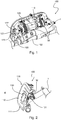
- the conditional opening mechanism 100 illustrated in figure 1 consists of the vent flap 110, coupled to the main shaft 102 of the handle 1 by eccentric connecting rods 103 in opposing mounting of return springs 32, and of a pivot connection 12 (cf. figure 3 ) composed of a locking shaft 120 integral with the shutter 110 and on which pressure levers 121 are mounted.
- Each pressure lever 121 comprises at their two ends a locking roller 122 and an unlocking roller 123.
- the leel opening mechanism 100 performs a locking / unlocking function by the pressure levers 121 and the door does not open.
- a negative pressure variation - the cabin pressure then being lower than the pressure outside the aircraft - the locking rollers 122 of the pressure levers 121 come into abutment and prevent the opening of the vent flap 110.
- this opening mechanism 100 avoids any mechanical interference.
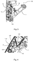
- the delayed movement is illustrated more particularly in the side sectional view of the opening mechanism 100 of the figure 3 .
- the internal handle 1 being directly mounted on the main shaft 102, the vent flap 110 is linked to the handle 1 via the pivot connection 12, and the two return springs 32 which tend to maintain contact.
- the shutter 110 and the handle 1 move together, the contact being provided by the springs 32.
- a delay in movement between the handle 1 and the shutter 110 occurs if a force greater than the return force of the springs 32 is applied to the shutter.
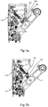
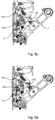
- the release cam 41 fixed to the main shaft 102, moves with the handle 1. Under nominal conditions, when the door is opened from the inside, each locking roller 122 first comes into contact with a stop 42 fixed to a side door fitting 10s (cf. figure 5a ). In a second step, the release cam 41 pushes the release roller 123 and forces the rotation of the locking shaft 120. The locking roller 122 releases from the stopper and the vent flap 110 is released to continue opening. . In other words, the contact of the locking rollers 123 on the stops 42 allows the release rollers 122 to roll under the cams 41 and to be released therefrom, which frees the opening of the shutter 110.
- the shutter 110 cannot open: the locking shaft 120 turns when the internal handle 1 is raised, the rollers release 123 roll under the cam 41 and the shutter 110 remains locked. In fact, before the release rollers 123 are released from the cams, the first locking rollers 122 come into contact with the stops 42 and block the mechanism 100: the shutter 110 cannot open.
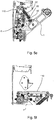
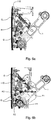
- the side sectional views of the opening mechanism 100 of the figures 5a to 5f relate to the essential opening sequences of the vent shutter 110 under normal (i.e. residual) pressure conditions by lowering the handle 1: the vent shutter 110 is first in the closed position with the locking roller 122 at a distance from the stop 42 ( figure 5a ); then the release roller 123 of the vent flap 110 comes into contact with the cam 41 ( figure 5b ); the locking roller 122 then comes into contact with the stop 42, causing a loss of contact between the handle 1 and the shutter 110 ( figure 5c ); the release of the vent flap 110 is then carried out by advancing the release roller 123 on the release cam 41 ( figure 5d ), followed by a rotation of the vent flap 110 by retraction of the springs 32 after release of the locking roller 122 from the stop 42 and a contact "K" between the handle 1 and the flap 110 ( figure 5e ); and the vent shutter 110 released ends in fully open position when internal handle 1 is fully lowered ( Figure 5f ).
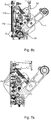
- the side sectional views of the figures 6a to 6c illustrate an opening sequence of the vent shutter 110 when the external face of the door structure 61 is covered with a layer of ice "G" which hinders the opening of said shutter: the vent shutter 110 is first of all in closed position ( figure 6a ); then the shutter 110 rotates with respect to the handle 1 (in rotation R1) with: a loss of contact in the zone K2 between the handle 1 and the shutter 110, a displacement of the shutter (arrow F1) and an induced pull of the shutter 110 (arrow F2) ( figure 6b ).
- the glass “G” is then broken around the periphery of the shutter 110, the breakage of the glass starting at the bottom of the shutter 110 thanks to the induced traction (arrow F2) and having repercussions on the rest of the shutter 110 to release it completely.
- the springs 32 then return the shutter 110 which turns (arrow F3) to come into contact with the handle 1 ( figure 6c ).
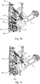
- a sequence of blocking the opening of the vent flap 110 is illustrated by the side views of the figures 7a to 7c in the case of overpressure, 0.138 bar (2 psi) in the example, of the cabin relative to the outside of the aircraft: the vent flap is closed with an overpressure of the cabin symbolized by the arrows F4 ( figure 7a ); then ( figure 7b ) the vent flap 110 is driven in rotation (arrow F5) until it comes into contact in the zone K3 with the rotation shaft 102 of the handle 1 actuated in rotation (arrow R1).
- the vent shutter 110 is maintained by the overpressure (arrows F4) in contact with the door structure 61 in the area K4 of the upper edge of the shutter 110, while a loss of contact K5 occurs between the handle 1 and the flap 110 with a contact between the shaft 102 of rotation of the handle 1 and the vent flap 110 ( figure 7b ).
- the locking roller 122 bears on the stop 42 and the contact is established in the zone K6 between the shaft 102 of the handle 1 and the vent flap 110 ( figure 7c ).
- FIG. 8a shows an exit door sign aircraft emergency according to the invention in partial front view from inside the cabin. Only the upper part 10a located above the window 16 of the door 10 appears in this figure. An example of a door strip 3 extends in the reduced space of this upper part 10a.
- the door opening mechanism comprises two hinges 80, which conventionally have the function of allowing pivoting about an axis X'X in the door frame and the door 10 being held until its open position. It also comprises a so-called locking / locking connection mechanism 8 between each hinge 80 and a lock 81 which comprises means duplicated on each side of the strip 3 on locking shafts 8A, in particular a lock 81 provided with a roller 8g traveling on an 8R guide ramp.
- the objective of these connections is to keep the door locked, in particular in azimuth with an aircraft in flight, whatever the constraints: singular fault in the mechanism, mechanical interference in the environment, loads tending to unlock, etc.
- the locking shaft 8A is mounted in the lower part of each hinge 80 and each lock 81, provided with the roller 8g driven on the guide ramp 8R, is mounted on the locking shaft 8A so that the lock 81 is directly connected to the corresponding hinge 80.
- a movement of the door in "Z plane” azimuth brings the latch 81 into contact with the latch guide ramp 8R and tends not to unlock the mechanism (that is to say the "over-lock” mechanism).
- the locks 81 mounted on the hinges 80 also prevent the door from moving in a Z plane.
- the door opening mechanism can only be activated when the locking / unlocking mechanism allows it.
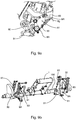
- This locking / unlocking mechanism 8 is more precisely illustrated by the side sectional view of the figure 9a .
- This mechanism comprises, for each hinge 80, a locking latch 91 and counter-latch system 92 combined with the latch 81 on its guide ramp 8R.
- the perspective view of the figure 9b shows, more generally, the mechanisms of door opening and locking / unlocking mounted on the main rotation shaft 102 of handle 1, as well as breaking cams 30 arranged at the ends of shaft 102 and intended for the preliminary opening phase for ice breaking.
- the function of the lock 81 is to keep the door closed whatever the flight conditions (acceleration, turbulence, depression, etc.).
- the function of the locking latch 91 is to keep the door secured by locking if a fault appears in the locking / unlocking mechanism.
- the function of the counter-latch 92 is to keep the latch 81 in place by holding the latch 91 and creating a positive moment which tends to over-lock the system, and therefore to prevent reverse driving of the mechanism.
- the counter-latch 92 and the latch 81 form the same part 90 while each performing the same functions as when the counter-latch and the lock are separated, as in previous architectures.
- the latch 91 and the counter-latch 92 are circular in shape.
- the counter-latch 92 comes into the latch 91 to guarantee a stop inside its internal face as soon as a rupture of the locking mechanism occurs. If the stopper occurs, the latch tends to overlock.
- Locking and locking compression spring rods 83 are present to respectively secure the locks 81 and the latches 91 by the exercise of a return force.
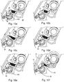
- the side sectional views of the figures 10a to 10f show six successive instants of the preliminary “round trip” movement sequence of the door 10 towards the interior of the car 20 with a minimum amplitude.
- This step is carried out by starting the rotation of the rupture cams 30 mounted on the main shaft 102, each being guided on a rupture lever 31 serving as a pivoting ramp.
- Each breaking lever 31 is mounted at one end 32 of a return spring 33.
- the cams 30, the levers 31 and the springs 32 form an ice breaking mechanism in the event that ice or frost has formed. deposited on the fuselage of the airplane at the level of the external door structure 61 (cf. figures 6a to 6c ).
- Door 10 first moves into the cabin from its initial closed position, causing the glass to break.
- This preliminary step therefore makes it possible to break the ice, typically an ice thickness of 2.5 mm on the external door structure 61.
- This step is carried out after the step of opening the vent flap 110, just after unlocking the hinges 81.
- the present architecture is independent of the latch-lock unlocking sequences and initiated directly by actuating the shaft of the locks from the internal handle 1, unlike previous architectures in which the door movements to break the glass are determined by the movements. and the kinematics of the locks.
- the figure 11 illustrates the fuselage frame guides 200 for the upper rollers 210a of the door 10 when the door is lowered, and the bypassing of the stops 220 of the fuselage frame.
- the rollers 210a coming from the lateral faces of the door 10 circulate in the guide ramps 200 formed in the frame of the fuselage and the door 10 arrives in the low position by bypassing the lower fuselage stops 220.
- the figures 12a and 12b illustrate an overall presentation of the emergency exit door 10, respectively in internal and external perspective views.
- the door 10 in the low position is positioned to pivot by a rotary drive around the axis X'X of rotation of the hinges 80.
- These figures also show the upper door guide rollers 210a, the door stops 13 on the side flanks 11f, a locking / blocking detector 12, a manual grip belt 14, advantageously a door blocking system in flight.
- window lock 15 for weakly secured cases between 0 bar (0 psi) and the pressure used for calibrating the springs, around 0.069 bar (1 psi) in the example
- window 16 from same dimension as the other passenger windows of the aircraft fuselage
- vent flap 110 forming an external handle 17 with the door opening button 130 from the outside.
- the invention relates to a multifunctional combination of opening mechanisms integrated with a connection to the shutter 110.
- This connection can be either direct, if the shutter is placed under the internal handle 1 as illustrated for example by the figures 1 or 2 , or adapted to an offset position of the shutter 110 due to the dimensions of this shutter (depending on the pressurization values) and the available space.
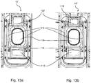
- Such a shutter 110 offset under the window 16, is illustrated by the front view of the emergency exit door 10 'of the figure 13a from inside the cabin.
- coupling rods 310 connect the main shaft 102 and the locking shaft 120 of the shutter 110.
- two shutters 110 can be used at the two locations described above with reference to figures 1 or 2 , namely above and under the window 16.
Landscapes
- Engineering & Computer Science (AREA)
- Mechanical Engineering (AREA)
- Aviation & Aerospace Engineering (AREA)
- Lock And Its Accessories (AREA)
- Special Wing (AREA)
- Pressure Vessels And Lids Thereof (AREA)
- Specific Sealing Or Ventilating Devices For Doors And Windows (AREA)
- Closing And Opening Devices For Wings, And Checks For Wings (AREA)
Claims (13)
- Flugzeugnotausgangstür (10, 10') mit durch Gruppierung integrierten Öffnungsmechanismen, wobei diese Gruppierung von Öffnungsmechanismen der Tür in einer Gruppierungsleiste (3) ausgeführt ist, die sich auf einer Seite einer Luke (16) mit Standardabmessungen befindet, umfassend einen Innengriff (1) zum Öffnen der Tür, der an einer Hauptwelle (102) montiert ist, die mit einer Verriegelungswelle (8A) in Verbindung steht, an der ein Türsperr-/Türverriegelungsmechanismus mit Klinke (91) und Riegel (81) montiert ist, zumindest einen Mechanismus (100) zur bedingten Türöffnung mit einer Lüftungsklappe (110), die in der Tür angeordnet ist und eine Unterkante (111) und eine Oberkante (K4) aufweist, einer Schwenkverbindung (12), die in der Tür angeordnet ist, um die Klappe (110) mit dem Innengriff (1) zu koppeln, und Federn (32) zum Zurückstellen der Klappe (110) in die geschlossene Position, um die Öffnung der Klappe (110) durch Ausüben eines reduzierten Drucks auf die Klappe (110) unter Bedingungen einer Restdruckänderung zwischen dem Flugzeuginneren und -äußeren zu ermöglichen, eine Sperrwelle (120) mit einem Druckhebel (121) an jedem Ende, der mit einer ersten und einer zweiten Rolle zum Sperren (122) bzw. Entsperren (123) der Klappe (110) ausgestattet ist, sowie einem Entsperrnocken (41), der an der Hauptwelle (102) befestigt ist, wobei unter Bedingungen einer Restdruckänderung zwischen dem Flugzeuginneren und- äußeren die Lüftungsklappe (110) sowie die fest mit der Klappe verbundene Sperrwelle (120), die in der Lage sind, sich durch Zurückziehen der Federn (32) um ihre Unterkante (111) zu drehen, es ermöglichen, dass sich der Entsperrnocken (41) mit dem Innengriff (1) bewegt und mit der Entsperrrolle (123) der Klappe (110) in Eingriff kommt und diese Entsperrrolle (123) so drückt, dass die Drehung der Sperrwelle (120) erzwungen wird, um die Sperrrolle (122) von einem Türanschlag (42) zu lösen und die Lüftungsklappe (110) freizugeben, und wobei unter Überdruckbedingungen die Federn (32) so kalibriert sind, dass sie bewirken, dass sich die Lüftungsklappe (110) durch Betätigung des Innengriffs (1) nicht um ihre Unterkante (111) dreht, der Entsperrnocken (41) nicht mit der Entsperrrolle (123) in Eingriff kommt und die Sperrrolle (122) mit dem Anschlag (42) in Kontakt kommt, wodurch das Öffnen der Klappe (110) verhindert wird.
- Notausgangstür (10, 10') nach Anspruch 1, dadurch gekennzeichnet, dass der Anschlag (42) an einem Türbeschlag (10s) befestigt ist, dass unter Bedingungen einer Restdruckänderung die Druckhebel (121) und die Klappe (110) in der Lage sind, sich durch Betätigung des Innengriffs (1) gemeinsam zu bewegen und das Öffnen der Klappe (110) zu ermöglichen, und dass unter Überdruckbedingungen die Klappe (110), die in der Lage ist, sich um ihre Oberkante zu drehen, bis sie mit der durch den Griff (1) betätigten Hauptwelle (102) in Kontakt (F5, R1) kommt, an der Tür (10, 10') bleibt und die Sperrrolle (122) mit dem Anschlag (42) in Kontakt kommt, um die Klappe (110) zu sperren und zu verhindern, dass sich die Entsperrrolle (123) vom Nocken (41) löst.
- Notausgangstür nach einem der Ansprüche 1 oder 2, wobei an einer Außenfläche (112) der Lüftungsklappe (110) ein Klappenknopf (19) vorgesehen ist, um einen Öffnungsnocken (131) zu betätigen, die Druckhebel (121) außer Eingriff zu bringen und so die Öffnung der Tür von außerhalb des Flugzeugs zu ermöglichen.
- Notausgangstür nach einem der vorangehenden Ansprüche, wobei der Sperr-/Verriegelungsmechanismus eine Sperrklinke (91) für jeden Riegel umfasst, die im Wesentlichen an einem Scharnier (80) zum Schwenken und Halten der Tür (10, 10') in der offenen Position montiert ist, wobei eine solche Montage es ermöglicht, dass jede Bewegung der Tür in einem relativen Azimut zum Flugzeug gesperrt wird.
- Notausgangstür nach einem der vorangehenden Ansprüche, wobei der Sperr-/Verriegelungsmechanismus aus einer Baugruppe aus Sperrklinke (91) und Gegensperrklinke (92) ausgebildet ist, der mit jedem Riegel (81) kombiniert ist, wobei die Gegenklinke (92) und der Riegel (81) jeder Baugruppe, die auf derselben Verriegelungswelle (8A) montiert sind, ein einziges Teil ausbilden.
- Notausgangstür nach einem der vorangehenden Ansprüche, wobei die Klinke (91) so konfiguriert ist, dass sie den Riegel (81) umschließt und in Position hält, wenn der Verriegelungsmechanismus bricht, um die Tür in einem sicheren Zustand zu halten.
- Notausgangstür nach einem der vorangehenden Ansprüche, wobei die Gegenklinke (92) so konfiguriert ist, dass sie einen Vorsprung innerhalb der Klinke (91) ausbildet, wodurch ein Anschlag bereitgestellt wird, sobald ein Bruch des Verriegelungsmechanismus auftritt.
- Notausgangstür nach einem der vorangehenden Ansprüche, wobei in die Mechanismengruppierungsleiste (3) auch ein Glasbruchmechanismus (30, 31, 32) integriert ist, wobei dieser Glasbruchmechanismus an jedem Ende der Leiste (3) einen Nocken (30) umfasst, der auf der Hauptwelle (102) montiert ist, wobei jeder Nocken (30) durch eine Schwenkrampe (31) in Verbindung mit einer Rückstellfeder (33) geführt wird, um durch die Betätigung der Verriegelungswelle durch den Innengriff eine Türöffnungssequenz mit minimaler Amplitude in Richtung des Passagierkabineninneren zu ermöglichen und eine bestimmte Glasdicke zu durchbrechen.
- Notausgangstür nach einem der vorangehenden Ansprüche, dadurch gekennzeichnet, dass sich die Leiste (3) zur Gruppierung der Türöffnungsmechanismen horizontal über der Luke (16) erstreckt, wobei sich die Tür (10, 10') durch Schwenken um eine horizontale Achse (X'X), die im Wesentlichen mit einer Oberkante der Nottür (10, 10') zusammenfällt, öffnen kann und wobei die Klappe (110) in Verbindung mit Kopplungsstangen (301), die die Hauptwelle (102) und die Sperrwelle (120) der Klappe (110) verbinden, auf Höhe der Leiste und/oder versetzt unter der Luke (16) angeordnet ist.
- Verfahren zum Öffnen/Schließen einer Flugzeugnotausgangstür nach einem der vorangehenden Ansprüche, wobei diese Tür (10, 10') an einem Flugzeugflügel angeordnet ist, um eine Evakuierung der Passagierkabine zu ermöglichen, wobei die Kinematik zum Schließen der Tür (10, 10') die nachstehenden Öffnungsschritte in umgekehrter Reihenfolge wiederholt, wobei das Verfahren dadurch gekennzeichnet ist, dass es darin besteht, eine Kinematik zum Öffnen einer in einem Rahmen des Flugzeugrumpfs angeordneten Tür ausgehend von einem Ausgangszustand der Tür in geschlossener Position mit einem mit dem Rumpf ausgerichteten Profil gemäß der folgenden Abfolge von Schritten auszuführen, die nacheinander durch eine einzige Einwirkung, die auf einen Innengriff (1) in einer einzigen Schwenksequenz um eine Hauptwelle (102) ausgeübt wird, erzeugt werden:- einen ersten Schritt des Öffnens einer Lüftungsklappe (110) des Mechanismus (100) zur bedingten Öffnung, wenn eine Druckänderung zwischen der Kabine und dem Äußeren des Flugzeugs geringer als ein bestimmter Restwert ist;- einen Schritt des Entsperrens/Entriegelns durch Aktivieren einer Bewegung der Klinken (91) zum Entsperren der Riegel (81) und Zurückziehen dieser entsperrten Riegel, um die Entsperrung durch Freigeben der Hauptwelle (102) abzuschließen;- einen Schritt des Öffnens der Tür durch Drehung der Hauptwelle (102), die eine Kippbewegung der Tür (10, 10') in Richtung des Kabineninneren bewirkt;- einen Schritt der Translation im Wesentlichen parallel zum Rumpf in Verbindung mit einer Führung im Türrahmen (200) und einer Umgehung der Rumpfanschläge (220) und- einen Schritt des Schwenkens der Tür (10, 10'), die um eine Drehachse (X'X) der Scharniere (80) angetrieben und bei dieser Drehung durch seitlich angeordnete Stellglieder (18) unterstützt wird.
- Öffnungsverfahren nach dem vorangehenden Anspruch, wobei ein Überdruckzustand zwischen dem Inneren und dem Äußeren des Flugzeugs, der größer als ein gegebener Schwellenwert ist, den Mechanismus (100) zur bedingten Öffnung während seines Betriebs sperrt, um die Öffnung der Lüftungsklappe (110) im ersten Schritt zu verhindern.
- Öffnungsverfahren nach einem der Ansprüche 10 oder 11, wobei ein vorbereitender Schritt der Öffnung der Tür (10, 10') in Richtung des Kabineninneren mit einer minimalen Amplitude durch Einleitung einer Drehung von Brechernocken (30) erzeugt wird, die auf der Hauptwelle (102) in Verbindung mit einer Führungsrampe (31) montiert sind, die mit einer Rückstellfeder (32) gekoppelt ist, wobei dieser Schritt nach dem Schritt des Öffnens der Lüftungsklappe und vor dem Schritt des Entsperrens/Entriegelns ausgeführt wird.
- Öffnungsverfahren nach einem der Ansprüche 10 bis 12, wobei die Einleitung der vorbereitenden Drehung, die dazu bestimmt ist, das Glas zu brechen, durch eine Hin- und Herdrehung/-gegendrehung gemäß einer geeigneten Konfiguration der Brechernocken (30) erfolgt.
Applications Claiming Priority (3)
| Application Number | Priority Date | Filing Date | Title |
|---|---|---|---|
| FR1560538A FR3043058A1 (fr) | 2015-11-03 | 2015-11-03 | Porte de sortie d'urgence d'avion a mecanismes integres et procede d'ouverture/fermeture d'une telle porte |
| FR1600293A FR3043059B1 (fr) | 2015-11-03 | 2016-02-19 | Porte de sortie d'urgence d'avion a mecanismes integrees et procede d'ouverture/fermeture d'une telle porte |
| PCT/EP2016/076324 WO2017076848A1 (fr) | 2015-11-03 | 2016-11-02 | Porte de sortie d'urgence d'avion à mécanismes integrés et procédé d'ouverture/fermeture d'une telle porte |
Publications (2)
| Publication Number | Publication Date |
|---|---|
| EP3371047A1 EP3371047A1 (de) | 2018-09-12 |
| EP3371047B1 true EP3371047B1 (de) | 2022-01-05 |
Family
ID=56555420
Family Applications (1)
| Application Number | Title | Priority Date | Filing Date |
|---|---|---|---|
| EP16795253.0A Active EP3371047B1 (de) | 2015-11-03 | 2016-11-02 | Flugzeugnotausgangstür mit integriertem mechanismus sowie verfahren zum öffnen und schliessen der tür |
Country Status (9)
| Country | Link |
|---|---|
| US (1) | US10752331B2 (de) |
| EP (1) | EP3371047B1 (de) |
| JP (1) | JP6804529B2 (de) |
| CN (1) | CN108349582B (de) |
| BR (1) | BR112018008872B1 (de) |
| CA (1) | CA3003933C (de) |
| FR (2) | FR3043058A1 (de) |
| RU (1) | RU2684950C1 (de) |
| WO (1) | WO2017076848A1 (de) |
Families Citing this family (15)
| Publication number | Priority date | Publication date | Assignee | Title |
|---|---|---|---|---|
| EP3981685B1 (de) * | 2018-12-07 | 2024-07-03 | Bombardier Inc. | Aussengriffpositionsanzeige für flugzeug-notausstiegsluke |
| FR3093701B1 (fr) | 2019-03-12 | 2021-04-02 | Latecoere | Porte d’aéronef à mécanisme d’ouverture conditionnelle selon deux trajectoires |
| BR102021018231A2 (pt) * | 2020-11-05 | 2022-05-17 | The Boeing Company | Conjunto de travamento de pressão coaxial |
| CN112591071B (zh) * | 2020-12-17 | 2022-03-15 | 中航沈飞民用飞机有限责任公司 | 一种舱门提升开启破冰机构 |
| CN113148223B (zh) * | 2021-05-06 | 2023-11-28 | 中航飞机起落架有限责任公司 | 一种飞行器舱门锁带预紧力安装方法 |
| CN113104193A (zh) * | 2021-05-17 | 2021-07-13 | 中国商用飞机有限责任公司 | 飞机舱门的增压预防机构 |
| US12442230B2 (en) * | 2021-11-09 | 2025-10-14 | Textron Innovations Inc. | Door stop mechanism |
| CN115182655B (zh) * | 2022-07-19 | 2023-10-31 | 中航沈飞民用飞机有限责任公司 | 一种民用飞机翼上无危险应急门 |
| US12515781B2 (en) | 2022-07-29 | 2026-01-06 | Textron Innovations Inc. | Retractable door pins for aircraft door |
| CN115556918B (zh) * | 2022-11-01 | 2025-04-04 | 中国商用飞机有限责任公司 | 飞机舱门增压预防装置 |
| US12168505B2 (en) | 2022-12-22 | 2024-12-17 | The Boeing Company | Separating door venting functions isolating means to prevent pressurization and handle lockout due to high cabin pressure |
| US12297677B2 (en) | 2022-12-22 | 2025-05-13 | The Boeing Company | Reduced volume latch, lock, vent and handle mechanism for an apparatus door |
| USD1066211S1 (en) * | 2023-03-28 | 2025-03-11 | Icarus Aero Inc. | DHC-8 aircraft emergency door |
| FR3159146B1 (fr) * | 2024-02-13 | 2026-02-06 | Latecoere | Mécanisme d’ouverture pour porte d’aéronef à échappement de butées |
| FR3159145A1 (fr) * | 2024-02-13 | 2025-08-15 | Latecoere | Ouvrant d’aéronef à déflecteur perfectionné |
Family Cites Families (11)
| Publication number | Priority date | Publication date | Assignee | Title |
|---|---|---|---|---|
| JP2637251B2 (ja) * | 1989-11-13 | 1997-08-06 | 財団法人日本航空機開発協会 | 緊急避難用扉開閉操作モードの切換装置 |
| US5031863A (en) * | 1989-12-21 | 1991-07-16 | The Boeing Company | Upward/outward opening, plug-type overwing emergency exit hatch |
| US5064147A (en) * | 1990-02-12 | 1991-11-12 | The Boeing Company | Upwardly opening plug-type door for use as an over-wing emergency hatch |
| US5305969A (en) * | 1991-07-16 | 1994-04-26 | The Boeing Company | Aircraft door latch lock mechanism |
| US5337977A (en) * | 1993-01-29 | 1994-08-16 | The Boeing Company | Vent-latch interlock assembly for an aircraft door |
| US5738303A (en) * | 1995-05-15 | 1998-04-14 | The Boeing Company | Mechanism for arming, disarming and activating airplane emergency slide evacuation systems |
| US5931415A (en) * | 1997-05-09 | 1999-08-03 | The Boeing Company | Plug-type overwing emergency exit door assembly |
| RU2301176C1 (ru) * | 2006-03-20 | 2007-06-20 | Открытое акционерное общество "ОКБ Сухого" | Система эксплуатационного и аварийно-спасательного выхода |
| US8403265B2 (en) * | 2009-09-01 | 2013-03-26 | Textron Innovations, Inc. | Aircraft cabin door pressure vent system |
| EP2441666B1 (de) * | 2010-10-06 | 2013-05-22 | AGUSTAWESTLAND S.p.A. | Türanordnung, insbesondere für einen Hubschrauber, mit einer Notfallauslösungsvorrichtung |
| US20150014483A1 (en) | 2012-02-29 | 2015-01-15 | Bombardier Inc. | Connection assembly for aircraft door |
-
2015
- 2015-11-03 FR FR1560538A patent/FR3043058A1/fr active Pending
-
2016
- 2016-02-19 FR FR1600293A patent/FR3043059B1/fr not_active Expired - Fee Related
- 2016-11-02 BR BR112018008872-2A patent/BR112018008872B1/pt active IP Right Grant
- 2016-11-02 CA CA3003933A patent/CA3003933C/fr active Active
- 2016-11-02 US US15/773,221 patent/US10752331B2/en active Active
- 2016-11-02 CN CN201680064201.5A patent/CN108349582B/zh active Active
- 2016-11-02 RU RU2018120381A patent/RU2684950C1/ru active
- 2016-11-02 EP EP16795253.0A patent/EP3371047B1/de active Active
- 2016-11-02 JP JP2018520137A patent/JP6804529B2/ja active Active
- 2016-11-02 WO PCT/EP2016/076324 patent/WO2017076848A1/fr not_active Ceased
Non-Patent Citations (1)
| Title |
|---|
| None * |
Also Published As
| Publication number | Publication date |
|---|---|
| JP2018531836A (ja) | 2018-11-01 |
| BR112018008872B1 (pt) | 2022-01-25 |
| CA3003933A1 (fr) | 2017-05-11 |
| EP3371047A1 (de) | 2018-09-12 |
| CN108349582A (zh) | 2018-07-31 |
| FR3043059A1 (fr) | 2017-05-05 |
| WO2017076848A1 (fr) | 2017-05-11 |
| CA3003933C (fr) | 2024-01-02 |
| BR112018008872A2 (pt) | 2018-11-06 |
| US10752331B2 (en) | 2020-08-25 |
| BR112018008872A8 (pt) | 2019-02-26 |
| FR3043059B1 (fr) | 2018-12-07 |
| CN108349582B (zh) | 2021-05-11 |
| JP6804529B2 (ja) | 2020-12-23 |
| RU2684950C1 (ru) | 2019-04-16 |
| FR3043058A1 (fr) | 2017-05-05 |
| US20180319479A1 (en) | 2018-11-08 |
Similar Documents
| Publication | Publication Date | Title |
|---|---|---|
| EP3371047B1 (de) | Flugzeugnotausgangstür mit integriertem mechanismus sowie verfahren zum öffnen und schliessen der tür | |
| EP2234874B1 (de) | Flugzeugtür mit druckausgleichsöffnung | |
| EP3863921B1 (de) | Verfahren zum öffnen/schliessen einer flugzeugtür und flugzeug mit einem solchen verfahren | |
| EP2497663B1 (de) | Fahrzeugpaneel, das mit einem beweglichen Fenster ausgestattet ist, und entsprechendes Fahrzeug | |
| EP1254834B1 (de) | Schnelle Evakuationseinheit für ein Luftfahrzeug | |
| EP3802315B1 (de) | Notausgangstür für eine flugzeugkabine mit öffnungshilfsmechanismus | |
| EP0834651A1 (de) | Methode und Einrichtung um die Klappen einer Schubumkehrvorrichtung zu schliessen | |
| EP3938278B1 (de) | Flugzeugtür mit mechanismus zum bedingten öffnen entlang zweier trajektorien | |
| EP0592317B1 (de) | Notausstieg mit einer Doppelkonfiguration zur Notevakuierung des Flugzeugs nach der Landung auf dem Bodem oder im Meer | |
| EP3584157B1 (de) | Verfahren zum bewegen von frachtraumtüren des fahrwerks eines luftfahrzeugs | |
| FR2686568A1 (fr) | Porte d'aeronef pressurise, permettant d'evacuer la pression residuelle interne avant son ouverture et de limiter la mise en pression tant qu'elle n'est pas completement fermee. | |
| FR3021626A1 (fr) | Equipement de fuselage formant une porte d'acces et comprenant une vanne de regulation d'echappement d'air de pressurisation | |
| FR3067701B1 (fr) | Procede d'ouverture/fermeture d'un panneau mobile de porte d'aeronef et porte equipee d'un tel panneau mobile | |
| FR3072937B1 (fr) | Hublot largable de vehicule et vehicule. | |
| EP4516679B1 (de) | Überdrucktür für eine heckhaube eines triebwerkstragmastes eines flugzeugs | |
| FR3075165A1 (fr) | Procede d'ouverture/fermeture d'un hublot ouvrant de porte d'aeronef et porte equipee d'un tel hublot |
Legal Events
| Date | Code | Title | Description |
|---|---|---|---|
| STAA | Information on the status of an ep patent application or granted ep patent |
Free format text: STATUS: UNKNOWN |
|
| STAA | Information on the status of an ep patent application or granted ep patent |
Free format text: STATUS: THE INTERNATIONAL PUBLICATION HAS BEEN MADE |
|
| PUAI | Public reference made under article 153(3) epc to a published international application that has entered the european phase |
Free format text: ORIGINAL CODE: 0009012 |
|
| STAA | Information on the status of an ep patent application or granted ep patent |
Free format text: STATUS: REQUEST FOR EXAMINATION WAS MADE |
|
| 17P | Request for examination filed |
Effective date: 20180629 |
|
| AK | Designated contracting states |
Kind code of ref document: A1 Designated state(s): AL AT BE BG CH CY CZ DE DK EE ES FI FR GB GR HR HU IE IS IT LI LT LU LV MC MK MT NL NO PL PT RO RS SE SI SK SM TR |
|
| AX | Request for extension of the european patent |
Extension state: BA ME |
|
| DAV | Request for validation of the european patent (deleted) | ||
| DAX | Request for extension of the european patent (deleted) | ||
| STAA | Information on the status of an ep patent application or granted ep patent |
Free format text: STATUS: EXAMINATION IS IN PROGRESS |
|
| 17Q | First examination report despatched |
Effective date: 20190820 |
|
| GRAP | Despatch of communication of intention to grant a patent |
Free format text: ORIGINAL CODE: EPIDOSNIGR1 |
|
| STAA | Information on the status of an ep patent application or granted ep patent |
Free format text: STATUS: GRANT OF PATENT IS INTENDED |
|
| INTG | Intention to grant announced |
Effective date: 20210628 |
|
| GRAS | Grant fee paid |
Free format text: ORIGINAL CODE: EPIDOSNIGR3 |
|
| GRAA | (expected) grant |
Free format text: ORIGINAL CODE: 0009210 |
|
| STAA | Information on the status of an ep patent application or granted ep patent |
Free format text: STATUS: THE PATENT HAS BEEN GRANTED |
|
| AK | Designated contracting states |
Kind code of ref document: B1 Designated state(s): AL AT BE BG CH CY CZ DE DK EE ES FI FR GB GR HR HU IE IS IT LI LT LU LV MC MK MT NL NO PL PT RO RS SE SI SK SM TR |
|
| REG | Reference to a national code |
Ref country code: GB Ref legal event code: FG4D Free format text: NOT ENGLISH |
|
| REG | Reference to a national code |
Ref country code: CH Ref legal event code: EP |
|
| REG | Reference to a national code |
Ref country code: AT Ref legal event code: REF Ref document number: 1460310 Country of ref document: AT Kind code of ref document: T Effective date: 20220115 |
|
| REG | Reference to a national code |
Ref country code: DE Ref legal event code: R096 Ref document number: 602016068112 Country of ref document: DE |
|
| REG | Reference to a national code |
Ref country code: IE Ref legal event code: FG4D Free format text: LANGUAGE OF EP DOCUMENT: FRENCH |
|
| REG | Reference to a national code |
Ref country code: SE Ref legal event code: TRGR |
|
| REG | Reference to a national code |
Ref country code: LT Ref legal event code: MG9D |
|
| REG | Reference to a national code |
Ref country code: NL Ref legal event code: MP Effective date: 20220105 |
|
| REG | Reference to a national code |
Ref country code: AT Ref legal event code: MK05 Ref document number: 1460310 Country of ref document: AT Kind code of ref document: T Effective date: 20220105 |
|
| PG25 | Lapsed in a contracting state [announced via postgrant information from national office to epo] |
Ref country code: NL Free format text: LAPSE BECAUSE OF FAILURE TO SUBMIT A TRANSLATION OF THE DESCRIPTION OR TO PAY THE FEE WITHIN THE PRESCRIBED TIME-LIMIT Effective date: 20220105 |
|
| PG25 | Lapsed in a contracting state [announced via postgrant information from national office to epo] |
Ref country code: RS Free format text: LAPSE BECAUSE OF FAILURE TO SUBMIT A TRANSLATION OF THE DESCRIPTION OR TO PAY THE FEE WITHIN THE PRESCRIBED TIME-LIMIT Effective date: 20220105 Ref country code: PT Free format text: LAPSE BECAUSE OF FAILURE TO SUBMIT A TRANSLATION OF THE DESCRIPTION OR TO PAY THE FEE WITHIN THE PRESCRIBED TIME-LIMIT Effective date: 20220505 Ref country code: NO Free format text: LAPSE BECAUSE OF FAILURE TO SUBMIT A TRANSLATION OF THE DESCRIPTION OR TO PAY THE FEE WITHIN THE PRESCRIBED TIME-LIMIT Effective date: 20220405 Ref country code: LT Free format text: LAPSE BECAUSE OF FAILURE TO SUBMIT A TRANSLATION OF THE DESCRIPTION OR TO PAY THE FEE WITHIN THE PRESCRIBED TIME-LIMIT Effective date: 20220105 Ref country code: HR Free format text: LAPSE BECAUSE OF FAILURE TO SUBMIT A TRANSLATION OF THE DESCRIPTION OR TO PAY THE FEE WITHIN THE PRESCRIBED TIME-LIMIT Effective date: 20220105 Ref country code: ES Free format text: LAPSE BECAUSE OF FAILURE TO SUBMIT A TRANSLATION OF THE DESCRIPTION OR TO PAY THE FEE WITHIN THE PRESCRIBED TIME-LIMIT Effective date: 20220105 Ref country code: BG Free format text: LAPSE BECAUSE OF FAILURE TO SUBMIT A TRANSLATION OF THE DESCRIPTION OR TO PAY THE FEE WITHIN THE PRESCRIBED TIME-LIMIT Effective date: 20220405 |
|
| PG25 | Lapsed in a contracting state [announced via postgrant information from national office to epo] |
Ref country code: PL Free format text: LAPSE BECAUSE OF FAILURE TO SUBMIT A TRANSLATION OF THE DESCRIPTION OR TO PAY THE FEE WITHIN THE PRESCRIBED TIME-LIMIT Effective date: 20220105 Ref country code: LV Free format text: LAPSE BECAUSE OF FAILURE TO SUBMIT A TRANSLATION OF THE DESCRIPTION OR TO PAY THE FEE WITHIN THE PRESCRIBED TIME-LIMIT Effective date: 20220105 Ref country code: GR Free format text: LAPSE BECAUSE OF FAILURE TO SUBMIT A TRANSLATION OF THE DESCRIPTION OR TO PAY THE FEE WITHIN THE PRESCRIBED TIME-LIMIT Effective date: 20220406 Ref country code: FI Free format text: LAPSE BECAUSE OF FAILURE TO SUBMIT A TRANSLATION OF THE DESCRIPTION OR TO PAY THE FEE WITHIN THE PRESCRIBED TIME-LIMIT Effective date: 20220105 Ref country code: AT Free format text: LAPSE BECAUSE OF FAILURE TO SUBMIT A TRANSLATION OF THE DESCRIPTION OR TO PAY THE FEE WITHIN THE PRESCRIBED TIME-LIMIT Effective date: 20220105 |
|
| PG25 | Lapsed in a contracting state [announced via postgrant information from national office to epo] |
Ref country code: IS Free format text: LAPSE BECAUSE OF FAILURE TO SUBMIT A TRANSLATION OF THE DESCRIPTION OR TO PAY THE FEE WITHIN THE PRESCRIBED TIME-LIMIT Effective date: 20220505 |
|
| REG | Reference to a national code |
Ref country code: DE Ref legal event code: R097 Ref document number: 602016068112 Country of ref document: DE |
|
| PG25 | Lapsed in a contracting state [announced via postgrant information from national office to epo] |
Ref country code: SM Free format text: LAPSE BECAUSE OF FAILURE TO SUBMIT A TRANSLATION OF THE DESCRIPTION OR TO PAY THE FEE WITHIN THE PRESCRIBED TIME-LIMIT Effective date: 20220105 Ref country code: SK Free format text: LAPSE BECAUSE OF FAILURE TO SUBMIT A TRANSLATION OF THE DESCRIPTION OR TO PAY THE FEE WITHIN THE PRESCRIBED TIME-LIMIT Effective date: 20220105 Ref country code: RO Free format text: LAPSE BECAUSE OF FAILURE TO SUBMIT A TRANSLATION OF THE DESCRIPTION OR TO PAY THE FEE WITHIN THE PRESCRIBED TIME-LIMIT Effective date: 20220105 Ref country code: EE Free format text: LAPSE BECAUSE OF FAILURE TO SUBMIT A TRANSLATION OF THE DESCRIPTION OR TO PAY THE FEE WITHIN THE PRESCRIBED TIME-LIMIT Effective date: 20220105 Ref country code: DK Free format text: LAPSE BECAUSE OF FAILURE TO SUBMIT A TRANSLATION OF THE DESCRIPTION OR TO PAY THE FEE WITHIN THE PRESCRIBED TIME-LIMIT Effective date: 20220105 Ref country code: CZ Free format text: LAPSE BECAUSE OF FAILURE TO SUBMIT A TRANSLATION OF THE DESCRIPTION OR TO PAY THE FEE WITHIN THE PRESCRIBED TIME-LIMIT Effective date: 20220105 |
|
| PLBE | No opposition filed within time limit |
Free format text: ORIGINAL CODE: 0009261 |
|
| STAA | Information on the status of an ep patent application or granted ep patent |
Free format text: STATUS: NO OPPOSITION FILED WITHIN TIME LIMIT |
|
| PG25 | Lapsed in a contracting state [announced via postgrant information from national office to epo] |
Ref country code: AL Free format text: LAPSE BECAUSE OF FAILURE TO SUBMIT A TRANSLATION OF THE DESCRIPTION OR TO PAY THE FEE WITHIN THE PRESCRIBED TIME-LIMIT Effective date: 20220105 |
|
| 26N | No opposition filed |
Effective date: 20221006 |
|
| PG25 | Lapsed in a contracting state [announced via postgrant information from national office to epo] |
Ref country code: SI Free format text: LAPSE BECAUSE OF FAILURE TO SUBMIT A TRANSLATION OF THE DESCRIPTION OR TO PAY THE FEE WITHIN THE PRESCRIBED TIME-LIMIT Effective date: 20220105 |
|
| PG25 | Lapsed in a contracting state [announced via postgrant information from national office to epo] |
Ref country code: MC Free format text: LAPSE BECAUSE OF FAILURE TO SUBMIT A TRANSLATION OF THE DESCRIPTION OR TO PAY THE FEE WITHIN THE PRESCRIBED TIME-LIMIT Effective date: 20220105 |
|
| REG | Reference to a national code |
Ref country code: CH Ref legal event code: PL |
|
| GBPC | Gb: european patent ceased through non-payment of renewal fee |
Effective date: 20221102 |
|
| REG | Reference to a national code |
Ref country code: BE Ref legal event code: MM Effective date: 20221130 |
|
| PG25 | Lapsed in a contracting state [announced via postgrant information from national office to epo] |
Ref country code: LI Free format text: LAPSE BECAUSE OF NON-PAYMENT OF DUE FEES Effective date: 20221130 Ref country code: IT Free format text: LAPSE BECAUSE OF FAILURE TO SUBMIT A TRANSLATION OF THE DESCRIPTION OR TO PAY THE FEE WITHIN THE PRESCRIBED TIME-LIMIT Effective date: 20220105 Ref country code: CH Free format text: LAPSE BECAUSE OF NON-PAYMENT OF DUE FEES Effective date: 20221130 |
|
| PG25 | Lapsed in a contracting state [announced via postgrant information from national office to epo] |
Ref country code: LU Free format text: LAPSE BECAUSE OF NON-PAYMENT OF DUE FEES Effective date: 20221102 |
|
| PG25 | Lapsed in a contracting state [announced via postgrant information from national office to epo] |
Ref country code: IE Free format text: LAPSE BECAUSE OF NON-PAYMENT OF DUE FEES Effective date: 20221102 Ref country code: GB Free format text: LAPSE BECAUSE OF NON-PAYMENT OF DUE FEES Effective date: 20221102 |
|
| PG25 | Lapsed in a contracting state [announced via postgrant information from national office to epo] |
Ref country code: BE Free format text: LAPSE BECAUSE OF NON-PAYMENT OF DUE FEES Effective date: 20221130 |
|
| PG25 | Lapsed in a contracting state [announced via postgrant information from national office to epo] |
Ref country code: HU Free format text: LAPSE BECAUSE OF FAILURE TO SUBMIT A TRANSLATION OF THE DESCRIPTION OR TO PAY THE FEE WITHIN THE PRESCRIBED TIME-LIMIT; INVALID AB INITIO Effective date: 20161102 |
|
| PG25 | Lapsed in a contracting state [announced via postgrant information from national office to epo] |
Ref country code: CY Free format text: LAPSE BECAUSE OF FAILURE TO SUBMIT A TRANSLATION OF THE DESCRIPTION OR TO PAY THE FEE WITHIN THE PRESCRIBED TIME-LIMIT Effective date: 20220105 |
|
| PG25 | Lapsed in a contracting state [announced via postgrant information from national office to epo] |
Ref country code: MK Free format text: LAPSE BECAUSE OF FAILURE TO SUBMIT A TRANSLATION OF THE DESCRIPTION OR TO PAY THE FEE WITHIN THE PRESCRIBED TIME-LIMIT Effective date: 20220105 |
|
| PG25 | Lapsed in a contracting state [announced via postgrant information from national office to epo] |
Ref country code: TR Free format text: LAPSE BECAUSE OF FAILURE TO SUBMIT A TRANSLATION OF THE DESCRIPTION OR TO PAY THE FEE WITHIN THE PRESCRIBED TIME-LIMIT Effective date: 20220105 |
|
| PG25 | Lapsed in a contracting state [announced via postgrant information from national office to epo] |
Ref country code: MT Free format text: LAPSE BECAUSE OF FAILURE TO SUBMIT A TRANSLATION OF THE DESCRIPTION OR TO PAY THE FEE WITHIN THE PRESCRIBED TIME-LIMIT Effective date: 20220105 |
|
| PGFP | Annual fee paid to national office [announced via postgrant information from national office to epo] |
Ref country code: DE Payment date: 20251117 Year of fee payment: 10 |
|
| PGFP | Annual fee paid to national office [announced via postgrant information from national office to epo] |
Ref country code: FR Payment date: 20251126 Year of fee payment: 10 |
|
| PGFP | Annual fee paid to national office [announced via postgrant information from national office to epo] |
Ref country code: SE Payment date: 20251121 Year of fee payment: 10 |