EP3371061B1 - Pivot flexible à grand angle - Google Patents
Pivot flexible à grand angle Download PDFInfo
- Publication number
- EP3371061B1 EP3371061B1 EP16810046.9A EP16810046A EP3371061B1 EP 3371061 B1 EP3371061 B1 EP 3371061B1 EP 16810046 A EP16810046 A EP 16810046A EP 3371061 B1 EP3371061 B1 EP 3371061B1
- Authority
- EP
- European Patent Office
- Prior art keywords
- flexible
- cylinder
- spokes
- interface structure
- pivot
- Prior art date
- Legal status (The legal status is an assumption and is not a legal conclusion. Google has not performed a legal analysis and makes no representation as to the accuracy of the status listed.)
- Active
Links
- 230000000063 preceeding effect Effects 0.000 claims 1
- 230000003287 optical effect Effects 0.000 description 6
- 230000007246 mechanism Effects 0.000 description 3
- 239000002245 particle Substances 0.000 description 3
- 238000005461 lubrication Methods 0.000 description 2
- 239000000463 material Substances 0.000 description 2
- 230000007935 neutral effect Effects 0.000 description 2
- 229910000831 Steel Inorganic materials 0.000 description 1
- RTAQQCXQSZGOHL-UHFFFAOYSA-N Titanium Chemical compound [Ti] RTAQQCXQSZGOHL-UHFFFAOYSA-N 0.000 description 1
- 230000004323 axial length Effects 0.000 description 1
- 238000005452 bending Methods 0.000 description 1
- 125000004122 cyclic group Chemical group 0.000 description 1
- 230000001627 detrimental effect Effects 0.000 description 1
- 230000000694 effects Effects 0.000 description 1
- 230000001747 exhibiting effect Effects 0.000 description 1
- 229910052751 metal Inorganic materials 0.000 description 1
- 239000002184 metal Substances 0.000 description 1
- 239000003921 oil Substances 0.000 description 1
- 238000005096 rolling process Methods 0.000 description 1
- 239000010959 steel Substances 0.000 description 1
- 239000010936 titanium Substances 0.000 description 1
- 229910052719 titanium Inorganic materials 0.000 description 1
Images


Classifications
-
- B—PERFORMING OPERATIONS; TRANSPORTING
- B64—AIRCRAFT; AVIATION; COSMONAUTICS
- B64G—COSMONAUTICS; VEHICLES OR EQUIPMENT THEREFOR
- B64G1/00—Cosmonautic vehicles
- B64G1/22—Parts of, or equipment specially adapted for fitting in or to, cosmonautic vehicles
- B64G1/66—Arrangements or adaptations of apparatus or instruments, not otherwise provided for
-
- F—MECHANICAL ENGINEERING; LIGHTING; HEATING; WEAPONS; BLASTING
- F16—ENGINEERING ELEMENTS AND UNITS; GENERAL MEASURES FOR PRODUCING AND MAINTAINING EFFECTIVE FUNCTIONING OF MACHINES OR INSTALLATIONS; THERMAL INSULATION IN GENERAL
- F16C—SHAFTS; FLEXIBLE SHAFTS; ELEMENTS OR CRANKSHAFT MECHANISMS; ROTARY BODIES OTHER THAN GEARING ELEMENTS; BEARINGS
- F16C11/00—Pivots; Pivotal connections
- F16C11/04—Pivotal connections
- F16C11/12—Pivotal connections incorporating flexible connections, e.g. leaf springs
-
- B—PERFORMING OPERATIONS; TRANSPORTING
- B64—AIRCRAFT; AVIATION; COSMONAUTICS
- B64G—COSMONAUTICS; VEHICLES OR EQUIPMENT THEREFOR
- B64G1/00—Cosmonautic vehicles
- B64G1/22—Parts of, or equipment specially adapted for fitting in or to, cosmonautic vehicles
- B64G1/222—Parts of, or equipment specially adapted for fitting in or to, cosmonautic vehicles for deploying structures between a stowed and deployed state
- B64G1/2228—Parts of, or equipment specially adapted for fitting in or to, cosmonautic vehicles for deploying structures between a stowed and deployed state characterised by the hold-down or release mechanisms
-
- G—PHYSICS
- G04—HOROLOGY
- G04B—MECHANICALLY-DRIVEN CLOCKS OR WATCHES; MECHANICAL PARTS OF CLOCKS OR WATCHES IN GENERAL; TIME PIECES USING THE POSITION OF THE SUN, MOON OR STARS
- G04B17/00—Mechanisms for stabilising frequency
- G04B17/04—Oscillators acting by spring tension
- G04B17/045—Oscillators acting by spring tension with oscillating blade springs
-
- G—PHYSICS
- G04—HOROLOGY
- G04B—MECHANICALLY-DRIVEN CLOCKS OR WATCHES; MECHANICAL PARTS OF CLOCKS OR WATCHES IN GENERAL; TIME PIECES USING THE POSITION OF THE SUN, MOON OR STARS
- G04B31/00—Bearings; Point suspensions or counter-point suspensions; Pivot bearings; Single parts therefor
-
- F—MECHANICAL ENGINEERING; LIGHTING; HEATING; WEAPONS; BLASTING
- F16—ENGINEERING ELEMENTS AND UNITS; GENERAL MEASURES FOR PRODUCING AND MAINTAINING EFFECTIVE FUNCTIONING OF MACHINES OR INSTALLATIONS; THERMAL INSULATION IN GENERAL
- F16C—SHAFTS; FLEXIBLE SHAFTS; ELEMENTS OR CRANKSHAFT MECHANISMS; ROTARY BODIES OTHER THAN GEARING ELEMENTS; BEARINGS
- F16C2326/00—Articles relating to transporting
- F16C2326/47—Cosmonautic vehicles, i.e. bearings adapted for use in outer-space
-
- Y—GENERAL TAGGING OF NEW TECHNOLOGICAL DEVELOPMENTS; GENERAL TAGGING OF CROSS-SECTIONAL TECHNOLOGIES SPANNING OVER SEVERAL SECTIONS OF THE IPC; TECHNICAL SUBJECTS COVERED BY FORMER USPC CROSS-REFERENCE ART COLLECTIONS [XRACs] AND DIGESTS
- Y10—TECHNICAL SUBJECTS COVERED BY FORMER USPC
- Y10T—TECHNICAL SUBJECTS COVERED BY FORMER US CLASSIFICATION
- Y10T403/00—Joints and connections
- Y10T403/45—Flexibly connected rigid members
Definitions
- the present invention relates generally to a flexible pivot comprising a first stage comprising a first interface structure and a second stage comprising a second interface structure in axial alignment with the first interface structure, the flexible pivot being arranged to be fixed to a base by one of the interface structures and to carry a load attached to the other interface, the flexible pivot comprising a first cylinder forming part of the first stage, a second cylinder in axial alignment with the first cylinder and forming part of the second stage, and a set of flexible connecting members for connecting the first and the second stages, each flexible connecting member comprising a pair of legs and a cross member joining the legs, each leg extending in a direction transverse to the axis of the cylinders, and the legs being attached to the first and the second cylinders respectively.
- Many space applications require actively controlling the orientation of certain devices on a satellite or a spacecraft.
- One example is controlling the orientation of an antenna in such a way that it remains pointed in the direction of a fixed location on the surface of the Earth.
- Another example is controlling the orientation of a mirror used to scan the surface of a celestial body.
- Such orientation control requires cyclic fine-pointing. Furthermore, this involves a very large number of cycles over the scanning range, on orbit.
- Space mechanisms are also subjected to micro-vibration generated by the surrounding equipment. They therefore require supports that decouple the optical system from the external micro-perturbations in order to maximize the optical performance.
- pivot mountings for space applications have to be made extremely robust and hard-wearing. For example, some pivot mountings have to be capable of withstanding up to 600,000,000 cycles. Other common requirements for pivot mountings are a great mechanical strength (to withstand both external forces and bending moments exerted on the mounted shaft), high transverse stiffness, high-precision zero-tolerance guidance, an amplitude of rotation of several tenths of degrees in both directions, and, a low resistive torque.
- FIG. 1 Flexible pivots are known.
- One such pivot is illustrated in figures 8 and 9 of published patent document EP 2 256 039 .
- Figure 1 of the present application is a duplicate copy of the above-mentioned figure 8 .
- the illustrated prior art flexible pivot meets the definition given in the introductory "field of the invention" paragraph of the present application. Indeed, as can be observed in figure 1 , the pivot comprises a first central cylinder 1 forming part of a first stage and two second cylinders 2a, 2b in axial alignment with the central cylinder and forming part of a second stage.
- the second cylinders are arranged symmetrically on each side of the first cylinder 1.
- the first or central cylinder 1 is arranged to serve as a first interface structure that may for example carry a load, while the two cylinders 2a, 2b are arranged to serve jointly as a second interface structure that may be connected to a fixed base that has not been depicted.
- the first and the second stages are connected by three flexible connecting members causing the pivot to exhibit 3-fold rotational symmetry.
- Each flexible connecting member comprises a pair of legs 7, 8a, 8b and a cross member (3a, 3b and 3c respectively) joining the legs, each leg extending in a direction transverse to the axis of the cylinders, and the legs being attached to the first 1 and the second 2a, 2b cylinders respectively.
- the flexible pivot comprises a first central cylinder 1 forming part of a first stage and two second cylinders 2a, 2b in axial alignment with the central cylinder and forming part of a fourth stage.
- the second cylinders are arranged symmetrically on each side of the first cylinder 1, and two additional cylinders 4a, 4b are further intercalated between the central cylinder and the second cylinders on either side.
- the additional cylinders 4a and 4b bridge the second and the third stages and they each are part of both of these stages.
- Each stage is connected to the following stage by flexible connecting members similar to the ones depicted in figure 1 .
- Each flexible connecting member comprises a pair of legs and a cross member joining the legs.
- the flexible connecting member joining the first and the second stage comprises the cross member 3 arranged to join legs 7, 8a and 8b.
- the prior art flexible pivot that has just been described should in principle provide twice the rotational range of the prior art pivot shown in figure 1 .
- the prior art device that has just been described has certain drawbacks.
- the four-stage pivot is also twice as long in the axial direction as the two-stage flexible pivot of figure 1 .
- the person skilled in the art will have no trouble understanding that increasing the length of the pivot in the axial direction may well be detrimental as far as axial stiffness is concerned.
- the stages in a multistage flexible pivot like the one depicted in figure 2 are separated by gaps and have low radial stiffness when actuated. In case of radial loading, the effect known as "center shift" can happen due to the low radial stiffness at each stage.
- a "direction transverse to an axis” should be understood as meaning a direction in a plane that is perpendicular to the axis in question.
- the first and the second cylinders are connected via flexible connection means to the first and the second interface structures respectively. Therefore, the flexible connection means arranged between each of the two cylinders and the corresponding interface structure contributes to the angular capacity of the flexible pivot. Furthermore, the first cylinder and the first interface structure are concentric and the flexible connection means connecting them together is implemented in the form of a set of spokes that are intercalated between the flexible connecting members. The spokes are arranged substantially in the same plane as the flexible legs of the connecting members that are attached to the first cylinder.
- a first advantage of the invention is therefore that the presence of the spokes brings about an increase of the rotational range of the flexible pivot without increasing the length of the pivot in the axial direction.
- a second advantage of the invention is that it makes it possible to determine independently the radial, axial, and rotational stiffness of the flexible pivot during the design phase.
- a third advantage of the invention is that the presence of the spokes and of the flexible connection means allows one to improve the centering of the axis, and thus to reduce the center shift drastically.
- At least the first stage of the flexible pivot preferably comprises flexible attachment means for attaching the outer end of each of the flexible spokes in the set to either the first interface structure or the first cylinder (whichever one of the two surrounds the other one).
- flexible attachment means is preferably implemented in the form of thin strips forming the outer end of each spoke. Each thin strip is oriented at an angle relative to the rest of the spoke, and at least a distal end of the thin strip is integrally connected to either the first interface structure or the first cylinder.
- the flexible attachment means allows the flexible pivot to accommodate to any change in the curvature of the spokes.
- the use of flexible attachment means also allows for custom tuning of the radial stiffness independently from the other degrees of freedom which permits to decouple the axis of the pivot from the external micro-vibrations on orbit.
- Another application of this tunable radial stiffness is to limit the travel under certain loading in order to keep an encoder head in the reading range for example or to define the clearance and its closing force for a launch lock system.
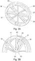
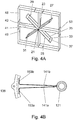
- Figures 3A and 4A show two flexible pivots that correspond respectively to two particular variants of a first exemplary embodiment of the invention.
- the flexible pivots of the invention are preferably formed as an integral structure made from a single piece of material.
- the material could be titanium or steel and the flexible pivot could be made out of a piece of metal by electro-erosion.
- the center of both the illustrated flexible pivots is formed by two hub portions in axial alignment with each other.
- the hub portions illustrated in figure 4A are not exactly cylindrical, all hub portions will be called cylinders in the following discussion.
- Figures 3A and 4A therefore both show a first cylinder 21, a second cylinder 23, and four flexible connecting members (referenced 25, 27, 29 and 31 respectively) for connecting the two cylinders.
- each connecting member comprises a pair of legs (33 and 35 respectively) and a cross member 37.
- the legs of the connecting members are arranged radially around the axis of the flexible pivot along a plane that is perpendicular to said axis, and that the cross member is attached to one end of each leg in such a way as to give the flexible connecting member the general shape of a U. It can further be observed that the other ends of the two legs of each U-shaped connecting member are attached to the first and the second cylinders respectively.
- the connecting members instead of being U-shaped, could be any shape considered to be adequate by a person skilled in the art.
- the flexible connecting members could be M-shaped like the prior art connecting members shown in figure 1 .
- each leg instead of extending along a radial direction, each leg could extend along a direction contained in a plane perpendicular to the axis of the pivot, but slightly inclined relatively to a radial direction.
- Both illustrated pivots further comprise a first interface structure and a second interface structure.
- the first and second interface structures shown are cylindrical and are referenced 38 and 39 respectively.
- the first and second interface structures of the flexible pivot depicted in figure 4A are in the shape of two square frames referenced 48 and 49 respectively.
- the flexible pivot is designed to be fixed to a base (not shown) by one of the interface structures and to carry a load (not shown) attached to the other interface structure.
- the first and the second interface structures are connected via flexible connection means to the first and the second cylinders respectively.
- the flexible connection means connecting the first interface structure and the first cylinder consist in a (first) set of flexible spokes 41 attached to the first cylinder 21 by one end and to the first interface structure 38 by the other end.
- the first and second interface structures are concentric with the first and second cylinders respectively, with the first and second interface structures surrounding the first and second cylinders.
- the flexible connection means that connects the second interface structure with the second cylinder consists in a second set of flexible spokes 43.
- the spokes 41 joining the first interface structure with the first cylinder, and the spokes 43 joining the second interface structure with the second cylinder are each shaped like a T-bar, each T-bar 41 or 43 being made up of an elongated stem, one end of which carries a thin strip 53 forming the crossbar of the T.
- each T-bar could extend along a direction contained in a plane perpendicular to the axis of the pivot, but slightly inclined relatively to a radial direction.
- the T-bars are each oriented with its crossbar at the outer end. Accordingly, the four flexible T-bars forming the first set of spokes 41 have their inner end attached to the first cylinder 21 and have the thin strip 53 forming their outer end attached to the first interface structure 38 or 48. In a similar fashion, the four flexible T-bars forming the second set of spokes 43 have their inner end attached to the second cylinder 23 and have the thin strip 53 forming their outer end attached to the second interface structure 39 or 49.
- first and second interface structures could be arranged concentrically inside the first and second cylinders, in such a way that it would be the first and second cylinders that would surround the first and second interface structures respectively.
- each T-bar would have its inner end attached to the first or the second interface structure, and would have the thin strip 53 forming its outer end attached to the first or second cylinder.
- Figure 3B is partial plane view of the flexible pivot of figure 3A having undergone a 45° rotation. Comparing figures 3A and 3B , it can be noted that, as shown in figure 3B , rotation of the first and second interface structures 38, 39, relatively to each other, has caused both the legs 33, 35 of each of the flexible connecting members 25, 27, 29, 31, as well as the stems of the spokes 41, 43 forming the flexible connection means, to bend substantially.
- the flexibility of the spokes 41, 43 as well as of the legs 33, 35 of the flexible connecting members contributes to the rotational range of the pivot.
- the flexible pivot comprises both first and second flexible attachment means for allowing the effective length of the spokes in the first and the second set of spokes to vary in such a way as to accommodate for any change in the curvature of the spokes.
- first and second flexible attachment means for allowing the effective length of the spokes in the first and the second set of spokes to vary in such a way as to accommodate for any change in the curvature of the spokes.
- the strips 53 are thin enough so they can deform elastically, making it possible for the point of attachment of the stem with the thin strip of each T-bar to move slightly in a radial direction relative to the axis of the flexible pivot.
- the elasticity of the thin strips also allows the orientation of the neutral plane of each one of them, at the point of attachment with the stem of the "T", to tilt slightly in such a way as to accommodate for the curvature of the stem during rotation of the complete pivot. It can further be seen that the thin strips 53 forming the outer end of each of the T-bar-shaped spokes in the second set of spokes 43 are integrally attached to the second interface structure 39 at either end.
- the first flexible attachment means comprise the thin strips 53 of the T-bar-shaped spokes 41 in the first set of spokes
- the second flexible attachment means comprise the thin strips 53 of the T-bar-shaped spokes 43 in the second set of spokes.
- the T-bar structure that has just been described corresponds to one of several possible implementations of the flexible attachment means arranged for allowing the effective length of the spokes to vary in such a way as to accommodate for an increase in the curvature of the spokes when the flexible pivot is turned from its rest position.
- the flexible connection means for connecting the first and second interfaces to the first and second cylinders could consist in two sets of L-bars.
- connection means connecting the first interface structure and the first cylinder consist in a first set of flexible spokes 141a, 141b attached to the first cylinder 121 by one end and to the first interface structure 138 by the other end. Furthermore, each spoke in the first set of spokes is shaped like a L-bar, each L-bar being made up of an elongated stem, one end of which carries a thin strip 153a or 153b forming the base of the L.
- each pair of L-bars 141a, 141b is arranged with the plan of symmetry of the pair oriented radially around the axis of the flexible pivot, the stem of each L-bar actually extending along a direction contained in a plane perpendicular to the axis of the pivot, but slightly inclined relatively to a radial direction.
- each one of the L-bars is oriented with its base at the outer end. Accordingly, the eight flexible L-bars 141a or 141b forming the first set of spokes have their inner end attached to the first cylinder 121 and have the thin strip 153a or 153b forming their outer end attached to the first interface structure 138.
- the first and second interface structures instead of surrounding the first and second cylinders, could be arranged concentrically inside the first and second cylinders, in such a way that it would be the first and second cylinders that would surround the first and second interface structures respectively.
- each L-bar would have its inner end attached to the first or the second interface structure, and would have the thin strip 153a or 153b forming its outer end attached to the first or second cylinder.
- the flexible pivot illustrated in figure 4B comprises flexible attachment means for allowing the effective length of the spokes to vary in such a way as to accommodate for any change in the curvature of the spokes.
- figure 4B shows that the thin strips 153a and 153b forming the outer end of each of the L-bar-shaped spokes 141a and 141b are integrally attached to the first interface structure 138 by their distal end.
- the thin strips 153a, 153b are thin enough so they can deform elastically, making it possible for the point of attachment of the stem with the thin strip of each L-bar to move slightly in a radial direction relative to the axis of the flexible pivot.
- the elasticity of the thin strips also allows the orientation of the neutral plane of each one of them, at the point of attachment with the stem of the "L”, to tilt slightly in such a way as to accommodate for the curvature of the stem during rotation of the complete pivot.
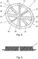
- Figures 5 and 6 are two views (a perspective view and a cross-sectional view) of a second exemplary embodiment of the invention.
- the flexible pivot depicted in figures 5 and 6 has a lot in common with the flexible pivots depicted in figures 3A, 3B and 4A .
- the elements of the flexible pivot of figures 5 and 6 that are identical or very similar to elements of the previous figures are designated by the same reference numbers.
- the flexible pivot according to the second embodiment comprises both a first interface structure and a second interface structure.
- the first interface structure 38 is very similar to that of the first exemplary embodiment.
- the second interface structure (referenced 59 is implemented in the form of a hub that is axially aligned with the first 21 and the second 23 cylinders.
- the flexible pivot comprises flexible connection means arranged to connect the second cylinder 23 and the second interface structure 59.
- the flexible connection means are implemented in the form of a second set of flexible connecting members 57.
- each flexible connecting member 57 comprises a pair of legs and a cross member joining one of the ends of each leg.
- the legs of the connecting members 57 are arranged radially around the axis of the flexible pivot along a plane that is perpendicular to said axis.
- each connecting member 57 is attached to the second cylinder and to the second interface structure 59 respectively.
- the legs of the second connecting members that are attached to the second cylinder are intercalated between the corresponding legs of the first connecting members 25, 27, 29 and 31.
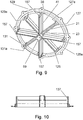
- Figures 7, 8 , 9 and 10 show a third and a fourth embodiment of the flexible pivot according to the invention.
- the first set of flexible connecting members comprises twelve connecting members (25, 25a, 25b, 27, 27a, 27b, 29, 29a, 29b, 31, 31a and 31b respectively) instead of four.
- the flexible connecting members 157 in the second set of flexible connecting members each comprise two pairs of legs, one leg of each pair being attached to the second cylinder 23 and the other leg of each pair being attached to the second interface structure 59, and the legs of both pairs being joined by a cross member (referenced 137 in figures 7, 8 and 10 ).
- the first set of flexible connecting members comprises eight connecting members (125, 125a, 127, 127a, 129, 129a, 131 and 131a respectively) instead of four or twelve.
- the flexible connecting members of the first set of flexible connecting members are grouped two by two.
- any embodiment of the flexible pivot of the invention can be equipped with flexible attachment means in the form of T-bars, L-bars or any other form that will seem appropriate to the person skilled in the art.
- the spokes in the set of flexible spokes would not be shaped either like T-bars or like L-bars, but would preferably be shaped like simple blades or bars.
Landscapes
- Engineering & Computer Science (AREA)
- Remote Sensing (AREA)
- Aviation & Aerospace Engineering (AREA)
- General Engineering & Computer Science (AREA)
- Physics & Mathematics (AREA)
- General Physics & Mathematics (AREA)
- Mechanical Engineering (AREA)
- Pivots And Pivotal Connections (AREA)
Claims (15)
- Pivot flexible comportant un premier étage comprenant une première structure d'interface (38 ; 48 ; 138) et un deuxième étage comprenant une seconde structure d'interface (39 ; 49 ; 59) alignée coaxialement avec la première structure d'interface, le pivot flexible étant agencé pour être fixé à une base par l'une des structures d'interface et pour porter une charge fixée sur l'autre structure d'interface, le pivot flexible comportant un premier cylindre (21 ; 121) faisant partie du premier étage, un deuxième cylindre (23) aligné coaxialement avec le premier cylindre et faisant partie du deuxième étage, et un jeu d'éléments de liaison flexibles (25, 25a, 25b, 27, 27a, 27b, 29, 29a, 29b, 31, 31a, 31b) agencés pour relier le premier et le deuxième étage, chaque élément de liaison flexible comprenant une paire de pieds (33, 35) et une traverse (37) reliant les pieds, chaque pied étant orienté transversalement à l'axe des cylindres, et les pieds étant respectivement fixés au premier (21 ; 121) et au deuxième cylindre (23), dans lequel le premier cylindre (21 ; 121) et la première structure d'interface (38 ; 138) sont concentriques, le premier étage comprenant un jeu de rayons flexibles (41 ; 141a, 141b) fixés au premier cylindre (21 ; 121) par une extrémité et à la première structure d'interface (38 ; 138) par l'autre extrémité, chaque rayon étant orienté transversalement à l'axe du pivot, et dans lequel le deuxième étage comprend des moyens de liaison flexibles (43, 57, 157) agencés pour relier le deuxième cylindre (23) et la seconde structure d'interface (39 ; 49, 59) ; caractérisé en ce que les rayons sont intercalés entre des pieds (33) des éléments de liaison flexibles (25, 25a, 25b, 27, 27a, 27b, 29, 29a, 29b, 31, 31a, 31b) qui sont fixés au premier cylindre (21).
- Pivot flexible selon la revendication 1, caractérisé en ce que les rayons (41 ; 141a, 141b) du jeu de rayons flexibles comportent une extrémité intérieure et une extrémité extérieure, l'extrémité extérieure étant plus éloignée de l'axe du pivot que l'extrémité intérieure, et en ce que le premier étage comprend des premiers moyens de fixation flexibles (53, 153a, 153b) pour fixer l'extrémité extérieure de chacun des dits rayons flexibles (41 ; 141a, 141b) à la première structure d'interface (38, ; 48 ; 138) ou au premier cylindre.
- Pivot flexible selon la revendication 2, caractérisé en ce que l'extrémité extérieure de chaque rayon (41 ; 141a, 141b) du jeu de rayons forme une bande fine (53, 153a, 153b) faisant un angle par rapport à l'orientation du reste du rayon, au moins une extrémité distale de la bande fine étant solidaire de la première structure d'interface ou du premier cylindre.
- Pivot flexible selon la revendication 3, caractérisé en ce que chaque rayon (141a, 141b) du jeu de rayons présente la forme d'un L, la base du L étant constituée par la bande fine (153a, 153b), l'extrémité distale de la bande fine étant solidaire de la première structure d'interface ou du premier cylindre.
- Pivot flexible selon la revendication 3, caractérisé en ce que chaque rayon (41) du jeu de rayons présente la forme d'un « T », la barre transversale du « T » étant constituée par la bande fine (53), et en ce que les deux extrémités distales de la bande fine sont solidaires de la première structure d'interface ou du premier cylindre.
- Pivot flexible selon l'une quelconque des revendications précédentes, caractérisé en ce que le deuxième cylindre (23) et la seconde structure d'interface (39 ; 49) sont concentriques, en ce que ledit jeu de rayons flexibles (41 ; 141a, 141b) est un premier jeu de rayons flexibles, et en ce que les moyens de liaison flexibles comprennent un deuxième jeu de rayons flexibles (43) fixés au deuxième cylindre (23) par une extrémité et fixés à la seconde structure d'interface (39 ; 49) par l'autre extrémité, chaque rayon (43) du deuxième jeu de rayons flexibles étant orienté transversalement à l'axe du pivot.
- Pivot flexible selon la revendication 6, caractérisé en ce que les rayons (43) du deuxième jeu de rayons flexibles sont intercalés entre des pieds (35) les éléments de liaison flexibles (25, 25a, 25b, 27, 27a, 27b, 29, 29a, 29b, 31, 31a, 31b) qui sont fixés au deuxième cylindre (23).
- Pivot flexible selon la revendication 6 ou 7, caractérisé en ce que les rayons du deuxième jeu de rayons flexibles comprennent une extrémité intérieure et une extrémité extérieure, l'extrémité extérieure étant plus éloignée de l'axe du pivot que l'extrémité intérieure, et en ce que le deuxième étage comprend des deuxièmes moyens de fixation flexibles pour fixer l'extrémité extérieure de chacun des dits rayons flexibles (43) du deuxième jeu à la seconde structure d'interface (39 ; 49) ou au deuxième cylindre.
- Pivot flexible selon la revendication 8, caractérisé en ce que l'extrémité extérieure de chaque rayon (43) du deuxième jeu de rayons forme une bande fine (53) faisant un angle par rapport à l'orientation du reste du rayon, au moins une extrémité distale de la bande fine étant solidaire de la seconde structure d'interface (39 ; 49) ou du deuxième cylindre.
- Pivot flexible selon la revendication 9, caractérisé en ce que chaque rayon du deuxième jeu de rayons présente la forme d'un « L », la base du « L » étant constituée par la bande fine, l'extrémité distale de la bande fine étant solidaire de la seconde structure d'interface (39 ; 49) ou du deuxième cylindre.
- Pivot flexible selon la revendication 9, caractérisé en ce que chaque rayon (43) du deuxième jeu de rayons présente la forme d'un « T », la barre transversale du « T » étant constituée par la bande fine (53), et en ce que les deux extrémités distales de la bande fine sont solidaires de la seconde structure d'interface ou du deuxième cylindre.
- Pivot flexible selon l'une quelconque des revendications 1 à 5, caractérisé en ce que la seconde structure d'interface est alignée coaxialement avec le premier et le deuxième cylindre, en ce que le jeu d'éléments de liaison flexibles (25, 25a, 25b, 27, 27a, 27b, 29, 29a, 29b, 31, 31a, 31b) agencés pour relier le premier cylindre (21) et le deuxième cylindre (23) est un premier jeu d'éléments de liaison flexibles, et en ce que les moyens de liaison flexibles comprennent un deuxième jeu d'élément de liaison flexibles (57, 157), chaque élément de liaison flexible du deuxième jeu comprenant une paire de pieds et une traverse (137) reliant les pieds, et les pieds de chaque élément de liaison flexible du deuxième jeu étant respectivement fixés au deuxième cylindre (23) et à la seconde structure d'interface (59).
- Pivot flexible selon la revendication 12, caractérisé en ce que les pieds des éléments de liaison flexibles du deuxième jeu, qui sont fixés au deuxième cylindre, sont intercalés entre des pieds (33) des éléments de liaison flexibles du premier jeu (25, 25a, 25b, 27, 27a, 27b, 29, 29a, 29b, 31, 31a, 31b), qui sont fixés au deuxième cylindre.
- Pivot flexible selon la revendication 12 ou 13, caractérisé en ce que chaque élément de liaison flexible (157) du deuxième jeu d'éléments de liaison flexibles comprend deux paires de pieds, un pied de chaque paire étant fixé au deuxième cylindre (23) et l'autre pied de chaque paire étant fixé à la seconde structure d'interface (59), et les pieds des deux paires étant reliés par la traverse (137).
- Pivot flexible selon l'une quelconque des revendications précédentes, caractérisé en ce qu'il possède une symétrie de rotation d'ordre n (« n » étant un entier plus grand ou égal à 2), le nombre d'éléments de liaison flexibles (25, 25a, 25b, 27, 27a, 27b, 29, 29a, 29b, 31, 31a, 31b) du premier jeu d'éléments de liaison flexibles étant égal à n ou à un multiple entier de n.
Applications Claiming Priority (2)
| Application Number | Priority Date | Filing Date | Title |
|---|---|---|---|
| EP15193517.8A EP3165470A1 (fr) | 2015-11-06 | 2015-11-06 | Pivot flexible à grand angle |
| PCT/IB2016/056604 WO2017077469A1 (fr) | 2015-11-06 | 2016-11-03 | Pivot flexible à grand angle |
Publications (2)
| Publication Number | Publication Date |
|---|---|
| EP3371061A1 EP3371061A1 (fr) | 2018-09-12 |
| EP3371061B1 true EP3371061B1 (fr) | 2019-09-11 |
Family
ID=54477911
Family Applications (2)
| Application Number | Title | Priority Date | Filing Date |
|---|---|---|---|
| EP15193517.8A Withdrawn EP3165470A1 (fr) | 2015-11-06 | 2015-11-06 | Pivot flexible à grand angle |
| EP16810046.9A Active EP3371061B1 (fr) | 2015-11-06 | 2016-11-03 | Pivot flexible à grand angle |
Family Applications Before (1)
| Application Number | Title | Priority Date | Filing Date |
|---|---|---|---|
| EP15193517.8A Withdrawn EP3165470A1 (fr) | 2015-11-06 | 2015-11-06 | Pivot flexible à grand angle |
Country Status (5)
| Country | Link |
|---|---|
| US (1) | US11971069B2 (fr) |
| EP (2) | EP3165470A1 (fr) |
| CA (1) | CA3001804C (fr) |
| ES (1) | ES2747781T3 (fr) |
| WO (1) | WO2017077469A1 (fr) |
Families Citing this family (8)
| Publication number | Priority date | Publication date | Assignee | Title |
|---|---|---|---|---|
| EP3476748B1 (fr) | 2017-10-24 | 2020-07-15 | CSEM Centre Suisse d'Electronique et de Microtechnique SA - Recherche et Développement | Mécanisme pivot à éléments flexibles |
| CN110296144B (zh) * | 2019-04-26 | 2020-07-21 | 北京航空航天大学 | 一种零刚度柔性铰链 |
| EP3771840B1 (fr) | 2019-08-02 | 2022-03-09 | Sener Aeroespacial, S.A. | Pivot flexible pour applications spatiales |
| CN111503131B (zh) * | 2020-06-04 | 2024-11-22 | 华东交通大学 | 一种抗轴向拉压大转角柔性铰链 |
| CN112460447A (zh) * | 2020-11-05 | 2021-03-09 | 天津航天机电设备研究所 | 一种大角度柔性支撑装置 |
| EP4009113A1 (fr) | 2020-12-02 | 2022-06-08 | The Swatch Group Research and Development Ltd | Ensemble de guidages flexibles pour mécanisme résonateur rotatif, notamment d'un mouvement d horlogerie |
| EP4276543A1 (fr) | 2022-05-10 | 2023-11-15 | The Swatch Group Research and Development Ltd | Ensemble de guidages flexibles pour mécanisme résonateur rotatif d'horlogerie |
| US20250192429A1 (en) * | 2023-12-07 | 2025-06-12 | Macdonald, Dettwiler And Associates Corporation | Systems and methods for holding and releasing a large antenna reflector |
Family Cites Families (11)
| Publication number | Priority date | Publication date | Assignee | Title |
|---|---|---|---|---|
| US2907563A (en) * | 1957-05-23 | 1959-10-06 | Charles D Verde | Pivot |
| US3575475A (en) * | 1969-06-03 | 1971-04-20 | Singer General Precision | Flexure joint |
| US4499779A (en) * | 1982-06-07 | 1985-02-19 | M-B-W Inc. | Vibratory compactor |
| DE3241373A1 (de) * | 1982-11-09 | 1984-05-10 | Anschütz & Co GmbH, 2300 Kiel | Federgelenk |
| FR2781264B1 (fr) * | 1998-07-20 | 2000-09-01 | Suisse Electronique Microtech | Pivot flexible a axe interieur de pivotement |
| ITMI20061000A1 (it) * | 2006-05-22 | 2007-11-23 | Milano Politecnico | Giunto elastico a cerniera sferica traslante e sensore di forze e momenti perfezionato con tale giunto |
| FR2913078B1 (fr) | 2007-02-27 | 2009-11-20 | Alcatel Lucent | Pivot traversant a lames. |
| FR2945848B1 (fr) | 2009-05-19 | 2012-01-13 | Thales Sa | Pivot traversant a elements flexibles et engin spatial comportant un tel pivot |
| US8899869B2 (en) * | 2010-08-09 | 2014-12-02 | Michael Valois | Rotary flexure bearing |
| US9400378B2 (en) * | 2014-08-08 | 2016-07-26 | University Of Macau | Rotary flexure micropositioning stage with large rotational range |
| US9759263B1 (en) * | 2014-11-13 | 2017-09-12 | National Technology & Engineering Solutions Of Sandia, Llc | Rotation flexure with temperature controlled modal frequency |
-
2015
- 2015-11-06 EP EP15193517.8A patent/EP3165470A1/fr not_active Withdrawn
-
2016
- 2016-11-03 EP EP16810046.9A patent/EP3371061B1/fr active Active
- 2016-11-03 ES ES16810046T patent/ES2747781T3/es active Active
- 2016-11-03 CA CA3001804A patent/CA3001804C/fr active Active
- 2016-11-03 US US15/773,820 patent/US11971069B2/en active Active
- 2016-11-03 WO PCT/IB2016/056604 patent/WO2017077469A1/fr not_active Ceased
Non-Patent Citations (1)
| Title |
|---|
| None * |
Also Published As
| Publication number | Publication date |
|---|---|
| CA3001804A1 (fr) | 2017-05-11 |
| EP3371061A1 (fr) | 2018-09-12 |
| WO2017077469A1 (fr) | 2017-05-11 |
| US11971069B2 (en) | 2024-04-30 |
| EP3165470A1 (fr) | 2017-05-10 |
| CA3001804C (fr) | 2023-10-03 |
| US20180319517A1 (en) | 2018-11-08 |
| ES2747781T3 (es) | 2020-03-11 |
Similar Documents
| Publication | Publication Date | Title |
|---|---|---|
| CA3001804C (fr) | Pivot flexible a grand angle | |
| US9079672B2 (en) | Through-pivot with flexible elements and spacecraft comprising such a pivot | |
| US9212692B2 (en) | Compact flexible cardan joint and spacecraft comprising such a joint | |
| US11572918B2 (en) | Pivot mechanism with flexible elements for large-amplitude rotation guiding and pivot assembly comprising a plurality of said pivot mechanism | |
| IL221990A (en) | Multi-stage bending axis | |
| EP3819618A1 (fr) | Dispositif de support de capteur de couple | |
| CN103221308A (zh) | 隔振系统及其方法 | |
| US8734043B2 (en) | Webbed through pivot | |
| US11898614B2 (en) | Planar torsional spring | |
| JP6053530B2 (ja) | 摩擦ダンパー | |
| JPH0277913A (ja) | 摩擦なし回動シヤフト支持構造 | |
| EP3771840B1 (fr) | Pivot flexible pour applications spatiales | |
| JP6639943B2 (ja) | テン輪及び機械式時計 | |
| US3415479A (en) | Gimbal structure | |
| US12326694B2 (en) | Elastic retaining member for attaching a timepiece component to a support element | |
| JP5795014B2 (ja) | 反射鏡支持機構 | |
| JPH041206B2 (fr) | ||
| CN117382918A (zh) | 一种基于异质材料的承载结构和制造方法 | |
| JP4079933B2 (ja) | 導波管支持構造 |
Legal Events
| Date | Code | Title | Description |
|---|---|---|---|
| STAA | Information on the status of an ep patent application or granted ep patent |
Free format text: STATUS: UNKNOWN |
|
| STAA | Information on the status of an ep patent application or granted ep patent |
Free format text: STATUS: THE INTERNATIONAL PUBLICATION HAS BEEN MADE |
|
| PUAI | Public reference made under article 153(3) epc to a published international application that has entered the european phase |
Free format text: ORIGINAL CODE: 0009012 |
|
| STAA | Information on the status of an ep patent application or granted ep patent |
Free format text: STATUS: REQUEST FOR EXAMINATION WAS MADE |
|
| 17P | Request for examination filed |
Effective date: 20180409 |
|
| AK | Designated contracting states |
Kind code of ref document: A1 Designated state(s): AL AT BE BG CH CY CZ DE DK EE ES FI FR GB GR HR HU IE IS IT LI LT LU LV MC MK MT NL NO PL PT RO RS SE SI SK SM TR |
|
| AX | Request for extension of the european patent |
Extension state: BA ME |
|
| DAV | Request for validation of the european patent (deleted) | ||
| DAX | Request for extension of the european patent (deleted) | ||
| REG | Reference to a national code |
Ref country code: DE Ref legal event code: R079 Ref document number: 602016020572 Country of ref document: DE Free format text: PREVIOUS MAIN CLASS: B64G0001660000 Ipc: B64G0001220000 |
|
| GRAP | Despatch of communication of intention to grant a patent |
Free format text: ORIGINAL CODE: EPIDOSNIGR1 |
|
| STAA | Information on the status of an ep patent application or granted ep patent |
Free format text: STATUS: GRANT OF PATENT IS INTENDED |
|
| RIC1 | Information provided on ipc code assigned before grant |
Ipc: B64G 1/66 20060101ALI20190319BHEP Ipc: F16C 11/12 20060101ALI20190319BHEP Ipc: B64G 1/22 20060101AFI20190319BHEP |
|
| INTG | Intention to grant announced |
Effective date: 20190416 |
|
| GRAS | Grant fee paid |
Free format text: ORIGINAL CODE: EPIDOSNIGR3 |
|
| GRAA | (expected) grant |
Free format text: ORIGINAL CODE: 0009210 |
|
| STAA | Information on the status of an ep patent application or granted ep patent |
Free format text: STATUS: THE PATENT HAS BEEN GRANTED |
|
| AK | Designated contracting states |
Kind code of ref document: B1 Designated state(s): AL AT BE BG CH CY CZ DE DK EE ES FI FR GB GR HR HU IE IS IT LI LT LU LV MC MK MT NL NO PL PT RO RS SE SI SK SM TR |
|
| REG | Reference to a national code |
Ref country code: GB Ref legal event code: FG4D |
|
| REG | Reference to a national code |
Ref country code: CH Ref legal event code: EP |
|
| REG | Reference to a national code |
Ref country code: AT Ref legal event code: REF Ref document number: 1178148 Country of ref document: AT Kind code of ref document: T Effective date: 20190915 |
|
| REG | Reference to a national code |
Ref country code: DE Ref legal event code: R096 Ref document number: 602016020572 Country of ref document: DE Ref country code: IE Ref legal event code: FG4D |
|
| REG | Reference to a national code |
Ref country code: NL Ref legal event code: FP |
|
| REG | Reference to a national code |
Ref country code: LT Ref legal event code: MG4D |
|
| PG25 | Lapsed in a contracting state [announced via postgrant information from national office to epo] |
Ref country code: BG Free format text: LAPSE BECAUSE OF FAILURE TO SUBMIT A TRANSLATION OF THE DESCRIPTION OR TO PAY THE FEE WITHIN THE PRESCRIBED TIME-LIMIT Effective date: 20191211 Ref country code: NO Free format text: LAPSE BECAUSE OF FAILURE TO SUBMIT A TRANSLATION OF THE DESCRIPTION OR TO PAY THE FEE WITHIN THE PRESCRIBED TIME-LIMIT Effective date: 20191211 Ref country code: LT Free format text: LAPSE BECAUSE OF FAILURE TO SUBMIT A TRANSLATION OF THE DESCRIPTION OR TO PAY THE FEE WITHIN THE PRESCRIBED TIME-LIMIT Effective date: 20190911 Ref country code: FI Free format text: LAPSE BECAUSE OF FAILURE TO SUBMIT A TRANSLATION OF THE DESCRIPTION OR TO PAY THE FEE WITHIN THE PRESCRIBED TIME-LIMIT Effective date: 20190911 Ref country code: SE Free format text: LAPSE BECAUSE OF FAILURE TO SUBMIT A TRANSLATION OF THE DESCRIPTION OR TO PAY THE FEE WITHIN THE PRESCRIBED TIME-LIMIT Effective date: 20190911 Ref country code: HR Free format text: LAPSE BECAUSE OF FAILURE TO SUBMIT A TRANSLATION OF THE DESCRIPTION OR TO PAY THE FEE WITHIN THE PRESCRIBED TIME-LIMIT Effective date: 20190911 |
|
| PG25 | Lapsed in a contracting state [announced via postgrant information from national office to epo] |
Ref country code: AL Free format text: LAPSE BECAUSE OF FAILURE TO SUBMIT A TRANSLATION OF THE DESCRIPTION OR TO PAY THE FEE WITHIN THE PRESCRIBED TIME-LIMIT Effective date: 20190911 Ref country code: GR Free format text: LAPSE BECAUSE OF FAILURE TO SUBMIT A TRANSLATION OF THE DESCRIPTION OR TO PAY THE FEE WITHIN THE PRESCRIBED TIME-LIMIT Effective date: 20191212 Ref country code: LV Free format text: LAPSE BECAUSE OF FAILURE TO SUBMIT A TRANSLATION OF THE DESCRIPTION OR TO PAY THE FEE WITHIN THE PRESCRIBED TIME-LIMIT Effective date: 20190911 Ref country code: RS Free format text: LAPSE BECAUSE OF FAILURE TO SUBMIT A TRANSLATION OF THE DESCRIPTION OR TO PAY THE FEE WITHIN THE PRESCRIBED TIME-LIMIT Effective date: 20190911 |
|
| REG | Reference to a national code |
Ref country code: ES Ref legal event code: FG2A Ref document number: 2747781 Country of ref document: ES Kind code of ref document: T3 Effective date: 20200311 |
|
| REG | Reference to a national code |
Ref country code: AT Ref legal event code: MK05 Ref document number: 1178148 Country of ref document: AT Kind code of ref document: T Effective date: 20190911 |
|
| PG25 | Lapsed in a contracting state [announced via postgrant information from national office to epo] |
Ref country code: PT Free format text: LAPSE BECAUSE OF FAILURE TO SUBMIT A TRANSLATION OF THE DESCRIPTION OR TO PAY THE FEE WITHIN THE PRESCRIBED TIME-LIMIT Effective date: 20200113 Ref country code: AT Free format text: LAPSE BECAUSE OF FAILURE TO SUBMIT A TRANSLATION OF THE DESCRIPTION OR TO PAY THE FEE WITHIN THE PRESCRIBED TIME-LIMIT Effective date: 20190911 Ref country code: EE Free format text: LAPSE BECAUSE OF FAILURE TO SUBMIT A TRANSLATION OF THE DESCRIPTION OR TO PAY THE FEE WITHIN THE PRESCRIBED TIME-LIMIT Effective date: 20190911 Ref country code: PL Free format text: LAPSE BECAUSE OF FAILURE TO SUBMIT A TRANSLATION OF THE DESCRIPTION OR TO PAY THE FEE WITHIN THE PRESCRIBED TIME-LIMIT Effective date: 20190911 Ref country code: RO Free format text: LAPSE BECAUSE OF FAILURE TO SUBMIT A TRANSLATION OF THE DESCRIPTION OR TO PAY THE FEE WITHIN THE PRESCRIBED TIME-LIMIT Effective date: 20190911 |
|
| PG25 | Lapsed in a contracting state [announced via postgrant information from national office to epo] |
Ref country code: IS Free format text: LAPSE BECAUSE OF FAILURE TO SUBMIT A TRANSLATION OF THE DESCRIPTION OR TO PAY THE FEE WITHIN THE PRESCRIBED TIME-LIMIT Effective date: 20200224 Ref country code: CZ Free format text: LAPSE BECAUSE OF FAILURE TO SUBMIT A TRANSLATION OF THE DESCRIPTION OR TO PAY THE FEE WITHIN THE PRESCRIBED TIME-LIMIT Effective date: 20190911 Ref country code: SM Free format text: LAPSE BECAUSE OF FAILURE TO SUBMIT A TRANSLATION OF THE DESCRIPTION OR TO PAY THE FEE WITHIN THE PRESCRIBED TIME-LIMIT Effective date: 20190911 Ref country code: SK Free format text: LAPSE BECAUSE OF FAILURE TO SUBMIT A TRANSLATION OF THE DESCRIPTION OR TO PAY THE FEE WITHIN THE PRESCRIBED TIME-LIMIT Effective date: 20190911 |
|
| REG | Reference to a national code |
Ref country code: DE Ref legal event code: R097 Ref document number: 602016020572 Country of ref document: DE |
|
| PLBE | No opposition filed within time limit |
Free format text: ORIGINAL CODE: 0009261 |
|
| STAA | Information on the status of an ep patent application or granted ep patent |
Free format text: STATUS: NO OPPOSITION FILED WITHIN TIME LIMIT |
|
| PG2D | Information on lapse in contracting state deleted |
Ref country code: IS |
|
| PG25 | Lapsed in a contracting state [announced via postgrant information from national office to epo] |
Ref country code: DK Free format text: LAPSE BECAUSE OF FAILURE TO SUBMIT A TRANSLATION OF THE DESCRIPTION OR TO PAY THE FEE WITHIN THE PRESCRIBED TIME-LIMIT Effective date: 20190911 Ref country code: MC Free format text: LAPSE BECAUSE OF FAILURE TO SUBMIT A TRANSLATION OF THE DESCRIPTION OR TO PAY THE FEE WITHIN THE PRESCRIBED TIME-LIMIT Effective date: 20190911 Ref country code: LU Free format text: LAPSE BECAUSE OF NON-PAYMENT OF DUE FEES Effective date: 20191103 Ref country code: IS Free format text: LAPSE BECAUSE OF FAILURE TO SUBMIT A TRANSLATION OF THE DESCRIPTION OR TO PAY THE FEE WITHIN THE PRESCRIBED TIME-LIMIT Effective date: 20200112 |
|
| 26N | No opposition filed |
Effective date: 20200615 |
|
| REG | Reference to a national code |
Ref country code: BE Ref legal event code: MM Effective date: 20191130 |
|
| PG25 | Lapsed in a contracting state [announced via postgrant information from national office to epo] |
Ref country code: SI Free format text: LAPSE BECAUSE OF FAILURE TO SUBMIT A TRANSLATION OF THE DESCRIPTION OR TO PAY THE FEE WITHIN THE PRESCRIBED TIME-LIMIT Effective date: 20190911 |
|
| PG25 | Lapsed in a contracting state [announced via postgrant information from national office to epo] |
Ref country code: IE Free format text: LAPSE BECAUSE OF NON-PAYMENT OF DUE FEES Effective date: 20191103 |
|
| PG25 | Lapsed in a contracting state [announced via postgrant information from national office to epo] |
Ref country code: BE Free format text: LAPSE BECAUSE OF NON-PAYMENT OF DUE FEES Effective date: 20191130 |
|
| PG25 | Lapsed in a contracting state [announced via postgrant information from national office to epo] |
Ref country code: CY Free format text: LAPSE BECAUSE OF FAILURE TO SUBMIT A TRANSLATION OF THE DESCRIPTION OR TO PAY THE FEE WITHIN THE PRESCRIBED TIME-LIMIT Effective date: 20190911 |
|
| PG25 | Lapsed in a contracting state [announced via postgrant information from national office to epo] |
Ref country code: HU Free format text: LAPSE BECAUSE OF FAILURE TO SUBMIT A TRANSLATION OF THE DESCRIPTION OR TO PAY THE FEE WITHIN THE PRESCRIBED TIME-LIMIT; INVALID AB INITIO Effective date: 20161103 Ref country code: MT Free format text: LAPSE BECAUSE OF FAILURE TO SUBMIT A TRANSLATION OF THE DESCRIPTION OR TO PAY THE FEE WITHIN THE PRESCRIBED TIME-LIMIT Effective date: 20190911 |
|
| PG25 | Lapsed in a contracting state [announced via postgrant information from national office to epo] |
Ref country code: TR Free format text: LAPSE BECAUSE OF FAILURE TO SUBMIT A TRANSLATION OF THE DESCRIPTION OR TO PAY THE FEE WITHIN THE PRESCRIBED TIME-LIMIT Effective date: 20190911 |
|
| PG25 | Lapsed in a contracting state [announced via postgrant information from national office to epo] |
Ref country code: MK Free format text: LAPSE BECAUSE OF FAILURE TO SUBMIT A TRANSLATION OF THE DESCRIPTION OR TO PAY THE FEE WITHIN THE PRESCRIBED TIME-LIMIT Effective date: 20190911 |
|
| PGFP | Annual fee paid to national office [announced via postgrant information from national office to epo] |
Ref country code: NL Payment date: 20241120 Year of fee payment: 9 |
|
| PGFP | Annual fee paid to national office [announced via postgrant information from national office to epo] |
Ref country code: DE Payment date: 20241121 Year of fee payment: 9 |
|
| PGFP | Annual fee paid to national office [announced via postgrant information from national office to epo] |
Ref country code: GB Payment date: 20241120 Year of fee payment: 9 |
|
| PGFP | Annual fee paid to national office [announced via postgrant information from national office to epo] |
Ref country code: FR Payment date: 20241128 Year of fee payment: 9 |
|
| PGFP | Annual fee paid to national office [announced via postgrant information from national office to epo] |
Ref country code: IT Payment date: 20241126 Year of fee payment: 9 Ref country code: ES Payment date: 20241230 Year of fee payment: 9 |
|
| PGFP | Annual fee paid to national office [announced via postgrant information from national office to epo] |
Ref country code: CH Payment date: 20241201 Year of fee payment: 9 |