EP3371373B1 - Système de mobilier urbain - Google Patents
Système de mobilier urbain Download PDFInfo
- Publication number
- EP3371373B1 EP3371373B1 EP16809145.2A EP16809145A EP3371373B1 EP 3371373 B1 EP3371373 B1 EP 3371373B1 EP 16809145 A EP16809145 A EP 16809145A EP 3371373 B1 EP3371373 B1 EP 3371373B1
- Authority
- EP
- European Patent Office
- Prior art keywords
- street furniture
- base assembly
- base
- receiving portion
- mounting
- Prior art date
- Legal status (The legal status is an assumption and is not a legal conclusion. Google has not performed a legal analysis and makes no representation as to the accuracy of the status listed.)
- Active
Links
Images


Classifications
-
- E—FIXED CONSTRUCTIONS
- E01—CONSTRUCTION OF ROADS, RAILWAYS, OR BRIDGES
- E01F—ADDITIONAL WORK, SUCH AS EQUIPPING ROADS OR THE CONSTRUCTION OF PLATFORMS, HELICOPTER LANDING STAGES, SIGNS, SNOW FENCES, OR THE LIKE
- E01F9/00—Arrangement of road signs or traffic signals; Arrangements for enforcing caution
- E01F9/60—Upright bodies, e.g. marker posts or bollards; Supports for road signs
- E01F9/658—Upright bodies, e.g. marker posts or bollards; Supports for road signs characterised by means for fixing
- E01F9/673—Upright bodies, e.g. marker posts or bollards; Supports for road signs characterised by means for fixing for holding sign posts or the like
- E01F9/681—Upright bodies, e.g. marker posts or bollards; Supports for road signs characterised by means for fixing for holding sign posts or the like the sign posts being fastened by removable means, e.g. screws or bolts
-
- E—FIXED CONSTRUCTIONS
- E01—CONSTRUCTION OF ROADS, RAILWAYS, OR BRIDGES
- E01F—ADDITIONAL WORK, SUCH AS EQUIPPING ROADS OR THE CONSTRUCTION OF PLATFORMS, HELICOPTER LANDING STAGES, SIGNS, SNOW FENCES, OR THE LIKE
- E01F9/00—Arrangement of road signs or traffic signals; Arrangements for enforcing caution
- E01F9/60—Upright bodies, e.g. marker posts or bollards; Supports for road signs
- E01F9/623—Upright bodies, e.g. marker posts or bollards; Supports for road signs characterised by form or by structural features, e.g. for enabling displacement or deflection
- E01F9/627—Upright bodies, e.g. marker posts or bollards; Supports for road signs characterised by form or by structural features, e.g. for enabling displacement or deflection self-righting after deflection or displacement
-
- E—FIXED CONSTRUCTIONS
- E01—CONSTRUCTION OF ROADS, RAILWAYS, OR BRIDGES
- E01F—ADDITIONAL WORK, SUCH AS EQUIPPING ROADS OR THE CONSTRUCTION OF PLATFORMS, HELICOPTER LANDING STAGES, SIGNS, SNOW FENCES, OR THE LIKE
- E01F9/00—Arrangement of road signs or traffic signals; Arrangements for enforcing caution
- E01F9/60—Upright bodies, e.g. marker posts or bollards; Supports for road signs
- E01F9/658—Upright bodies, e.g. marker posts or bollards; Supports for road signs characterised by means for fixing
- E01F9/673—Upright bodies, e.g. marker posts or bollards; Supports for road signs characterised by means for fixing for holding sign posts or the like
Definitions
- the present invention relates to a street furniture system and in particular to a system that permits multiple discrete items of street furniture to be mounted together upon a common mounting plate.
- a base assembly is considered to be self-righting if it is able to deform in the event of a force being applied to it (e.g. from an impact) and then return or recover to its original or rest configuration when the force is removed.
- a base assembly is considered to be self-fronting if it is biased to a specific orientation and will return to that orientation after a force resulting in a rotational deflection is removed.
- a one-piece (i.e. unitary or monolithic) resiliently deformable base assembly can be provided which is self-supporting, self-righting and is self-fronting.
- the terms "one-piece”, “unitary” and “monolithic” are intended to mean that the base assembly is formed as a single component.
- the single component may include elements, such as reinforcing elements embedded within it.
- a street furniture system comprising a mounting plate, a plurality of self-righting and self-fronting street furniture base assemblies and a plurality of street furniture elements, wherein the mounting plate defines two or more base assembly mounting locations, a base assembly is secured to each base assembly mounting location, and each base assembly supports a respective street furniture element; characterised in that each base assembly is formed as a monolithic component from a polyurethane polymer and defines a base mounting portion, an intermediate portion, and an elongate street furniture receiving portion, wherein the intermediate portion is located between the street furniture receiving portion and the base mounting portion, the street furniture receiving portion projects from the intermediate portion, the intermediate portion has a minimum width which is greater than the corresponding width of the street furniture receiving portion, and the base mounting portion extends outwards from the intermediate portion; wherein a shoulder portion is defined between the street furniture receiving portion and the intermediate portion and the shoulder portion is inclined, curved or defines a step change in the width of the assembly between the street furniture receiving portion and the
- the use of a polyurethane polymer material as the material for the base assembly has been found to provide the necessary resistance to deflection away from an upright configuration (i.e. out of a vertical plane) and also against rotation about a vertical axis without the need for additional components.
- the one-piece or monolithic base assembly according to the invention can be said to be both self-righting and self-fronting.
- a base assembly forming part of the present invention requires only a single mould and a one-stage manufacturing process.
- Known street furniture systems do not include self-righting and self-fronting base assemblies in the form of a unitary component.
- the known base assemblies are either not self-righting and/or self-fronting, or they are not a single component.
- a monolithic polyurethane base assembly as claimed may be provided that is inherently self-righting (i.e. is able to re-orient the street furniture receiving portion to a substantially upstanding configuration following a deflection of this portion out of a vertical plane, e.g. following an impact by a vehicle) and self-fronting (i.e. is able to re-orient the street furniture receiving portion to a specific (rest) angular orientation following the receiving portion being twisted or rotated away from its rest orientation).
- the street furniture receiving portion supports an item of street furniture (i.e. a street furniture element).
- the street furniture receiving portion may be in the form of an elongate post and the respective street furniture element suitably includes (i) one or more complementary brackets via which the street furniture element is secured to the street furniture receiving portion of the base assembly, (ii) an aperture into which the post may be located, or (iii) a channel which is sized and shaped to receive therein the post in order to couple the street furniture element to the base assembly.
- other methods of securing the street furniture element to the street furniture receiving portion of the base assembly are within the scope of the present invention.
- the street furniture element may be secured directly to the street furniture receiving portion of the base assembly in use and thereby the street furniture element may be secured to the mounting plate via the base assembly.
- the street furniture element may be secured to the street furniture receiving portion of the base assembly via an intermediate component.
- the street furniture receiving portion may be an upstanding receiving portion in certain embodiments.
- upstanding is to be construed as meaning “upstanding in use”.
- the base assembly is secured in use to the mounting plate via the fixing element(s) of the base mounting portion.
- the base mounting portion extends outwards (e.g. radially or laterally outwards) from the street furniture receiving portion and may include a flange portion.
- The, some of the, or all of the fixing elements may be apertures defined by the flange portion.
- the polyurethane body of the base assembly may include one or more filler materials conventionally associated with elastomers. Such fillers may include carbon black and silica. Additionally or alternatively, the polyurethane may include one or more reinforcing materials, such as glass fibres, carbon fibres or the like.
- the polyurethane material provides desirable physical properties and demonstrates acceptable resistance to damage from environmental factors, such as liquids (organic and aqueous), light, weather, etc.
- the polyurethane material from which the base assembly is formed suitably has a hardness of from 70 to 100 on the Shore A hardness scale. In certain embodiments of the invention, the polyurethane from which the base assembly is formed has a hardness from 80 to 90 on the Shore A hardness scale.
- the base assembly further includes an intermediate portion located between the street furniture receiving portion and the base mounting portion, wherein the intermediate portion has a width (e.g. a minimum width) which is greater than the corresponding width of the street furniture receiving portion, and the base mounting portion extends outwards (e.g. radially or laterally outwards) from the intermediate portion.
- the intermediate portion may have a substantially constant width/diameter and consequently a substantially constant cross-sectional shape or it may have a variable width, for example a width which increases from the street furniture receiving portion to the base mounting portion.
- the force required to deflect an item secured to the base assembly may be at least in part determined by the physical characteristics of the intermediate portion (e.g. shape, width/diameter, length, etc.).
- the restorative force exerted by the base assembly when in a deflected configuration may also, at least in part, be determined by the physical characteristics of the intermediate portion.
- the respective street furniture element may engage and be at least partially supported by the shoulder portion defined between the street furniture receiving portion and the intermediate portion of the base assembly.
- the shoulder portion defines a step change in the in the width of the base assembly between the street furniture receiving portion and the intermediate portion.
- the shoulder portion may extend radially outwards from the street furniture receiving portion to define a substantially planar annular shoulder surface.
- the plane of the shoulder portion may be substantially parallel to the plane of the mounting plate to which the base assembly is secured (e.g. a horizontal plane).
- the shoulder portion may be sloped or inclined.
- An inclined shoulder portion is advantageous in preventing or minimising the risk of a bottom portion of the item of street furniture becoming trapped between the street furniture receiving portion and the intermediate portion when the base assembly is deflected.
- the sloped or inclined shoulder portion may be linear (i.e. the incline or slope defines a straight line) or it may be curved, such as concave, convex or bell-shaped.
- the or each fixing element carried by the base mounting portion is suitably a hole, i.e. a through hole or bore extending through the base mounting portion.
- Such holes are adapted to receive therethrough a suitable fixing, such as a bolt, which may be used to secure the base assembly to the mounting plate.
- a suitable fixing such as a bolt
- Each base assembly mounting location of the mounting plate may include one or more upstanding bolts corresponding to the holes extending through the respective base mounting portion or it may include through holes corresponding to the holes extending through the respective base mounting portion whereby a bolt or other fixing may pass through the aligned holes of the mounting plate and base mounting portion to secure the base assembly to the respective mounting location of the mounting plate.
- the holes of the base mounting portion are arranged as pairs of opposed holes.
- the holes may be circumferentially spaced around the base mounting portion such that each hole is diametrically opposed to its partner hole.
- the holes are equally spaced circumferentially about the base mounting portion. In this way, the base assembly is better able to withstand deflection forces from any direction.
- the base mounting portion includes an even number of fixing elements in the form of holes defined by a flange extending outwards from an intermediate portion or the street furniture receiving portion (as appropriate) and the holes are arranged about the flange as opposed pairs, and wherein the ratio between the width or diameter of the street furniture receiving portion/intermediate portion to the distance between a pair of opposed holes is from 1:1.1 to 1:25, suitably 1:1.1 to 1:2.
- the ratio between the width or diameter of the street furniture receiving portion/intermediate portion to the distance between a pair of opposed holes is from 1:1.1 to 1:25, suitably 1:1.1 to 1:2.
- the width or diameter of the street furniture receiving portion or, where present, the intermediate portion is measured parallel to a diameter between the opposed holes.
- the diameters are aligned with each other.
- the distance between a pair of opposed holes is considered to be the distance between the centres of the holes.
- the mounting plate may include one or more anchor elements.
- the anchor elements may include one or more ground anchors to help secure the mounting plate to the desired substrate (e.g. a road surface, an island surface or similar) or they may be elements which allow the mounting plate to be secured to a separate ground anchor component.
- the system may include a reinforcing plate secured to and/or embedded within the base assembly.
- a reinforcing plate may be located between the mounting plate and the base assembly, it may be embedded (partially or fully) within the body of the base assembly, and/or it may be located above the base mounting portion of the base assembly such that the base mounting portion is sandwiched between the mounting plate and a reinforcing plate.
- the reinforcing plate may be annular.
- An annular reinforcing plate may be located around the intermediate portion/street furniture receiving portion (i.e. the intermediate portion/street furniture receiving portion is located within the bore defined by the annular reinforcing plate) in order to reinforce the base mounting portion.
- the reinforcing plate may include holes or bores corresponding to the holes which form the fixing elements of the base assembly.
- the street furniture receiving portion of the present invention may be a substantially cylindrical post.
- a street furniture receiving portion comprising a post having a different cross-sectional shape is possible within the scope of the invention, including a post having a triangular, rectangular, pentagonal, hexagonal, heptagonal, octagonal, etc. cross-sectional shape.
- the intermediate portion where present, may have a cross-sectional shape as described above and the cross-sectional shape of the intermediate portion may be the same as or different to the cross-sectional shape of the street furniture receiving portion.
- the street furniture receiving portion may comprise a substantially upstanding post.
- the street furniture receiving portion may include one or more securing elements to secure thereto the respective street furniture element.
- the or each securing element may comprise a hole (i.e. a through hole or a bore) defined through the street furniture receiving portion though which a fixing may be located wherein the fixing retains the street furniture element in a desired orientation relative to the base assembly.
- the respective street furniture elements may be in the form of elongate blades.
- the system may include an intermediate component in the form of an extension member.
- the extension member suitably is received by and is coupled to the street furniture receiving portion of the base assembly and extends upwards beyond the street furniture receiving portion.
- the extension member may be secured to the street furniture receiving portion of the base assembly and the respective street furniture element may be secured to the extension member and optionally also to the base assembly.
- the extension member suitably includes a corresponding shaped lower portion such that it is able to mate with the street furniture receiving portion of the base assembly.
- the upper portion of the extension member may be shaped or configured to conform to a mating surface of the item of street furniture or it may have substantially the same shape and configuration as the lower portion of the extension member.
- the street furniture receiving portion is an upstanding post and the extension member defines a tubular bore which is sized and configured to receive therein the upstanding post.
- the street furniture elements may be in the form of elongate blades. Such blades may have a substantially planar face.
- street furniture is intended to cover items such as traffic signs, traffic bollards, lane delineators, lights and so forth. However, it is not limited to roads and is also intended to cover signs, bollards, delineators, barriers, lights, etc. when used in alternative environments, such as railways and airports.
- "street furniture" in the context of the present invention includes any supported body adapted to be carried by a base assembly, which is typically upstanding, and which is at risk of being hit by a moving vehicle.
- the base assembly may be formed by providing a mould for the base assembly, locating within the mould a polyurethane pre-cursor material, and allowing or causing the polyurethane pre-cursor material to cure in-situ to form a polyurethane polymer.
- Elastomers such as polyurethane
- a precursor material such as one or more monomers or non-vulcanised unsaturated rubber components, which is then reacted, chemically altered or vulcanised to achieve the final elastomeric product.
- the conversion of the precursor material into the final form of the elastomer is referred to herein as "curing".
- the curing step may include the addition of heat, pressure, a catalyst and/or a reactive component.
- the mould suitably defines a street furniture receiving portion, a base mounting portion and, optionally, an intermediate portion as defined herein.
- the polyurethane pre-cursor material is suitably cured by heat. Accordingly, the curing of the polyurethane pre-cursor material may include heating the mould with the polyurethane pre-cursor material located therein.
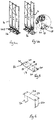
- Figure 1 shows street furniture system 2 comprising an array of three upstanding blades 4, each carried by a respective base assembly 102.
- FIGs 2a and 2b show an individual blade 4 and respective base assembly 102, detailing how the blade 4 is secured to the base assembly 102.
- the blade 4 comprises a substantially planar front surface 6 which may carry thereon indicia representing part of a roadsign system. Side portions 8 of the blade 4 are angled with respect to the front surface to provide the desired overall shape and a lower portion 10 of the blade 4 tapers inwards.
- the blade 4 is formed from HDPE (high density polyethylene).
- the base assembly 102 has an annular reinforcing ring 12 located over a base mounting portion thereof and the street furniture receiving portion receives thereover an extension tube 14 (i.e. the street furniture receiving portion is located in use within a central bore defined by the extension tube 14).
- the extension tube 14 is an extruded HDPE tube which has a length of about 655mm and the annular reinforcing ring 12 is formed from 3mm zinc plated steel.
- the base assembly 102 will be described in more detail hereinbelow with reference to Figure 3 .
- the blade 4 is secured about its midpoint to an upper portion of the extension tube 14 via a pair of bolts which extend through the blade and diametrically opposed holes formed through the extension tube 14.
- the bolts are secured via corresponding nuts and washers.
- the blade 4 is secured to both a lower portion of the extension tube 14 and the street furniture receiving portion of the base assembly 102.
- Diametrically opposed holes are formed in the lower portion of the extension tube 14 which align with corresponding holes formed through the street furniture receiving portion (described in more detail below) and bolts are located through the blade 4 and the aligned holes formed through the extension tube 14 and the street furniture receiving portion of the base assembly 102.
- Figure 3 shows a one-piece resiliently deformable base assembly 102 formed from a three component polyester-based polyurethane pre-cursor material sold under the trade name Diprane 530 and available from Dow Chemicals.
- the pre-cursor material includes a polyol component, an isocyanate component and a chain extending component. The formation of the base assembly 102 is described hereinbelow.
- the base assembly 102 comprises an intermediate portion 104 located between a base mounting portion in the form of a flange 106 which extends radially outwards from the bottom of the intermediate portion 104, and a street furniture receiving portion in the form of an upwardly projecting post 108.
- the base assembly 102 defines an inclined shoulder portion 110 such that the diameter of the base assembly 102 changes smoothly and constantly between the intermediate portion 104 and the narrower post 108.
- the inclined shoulder portion 110 is angled at 45°.
- the change in diameter is constant which results in a linear shoulder portion 110.
- a non-linear change in diameter is also within the scope of the invention, such that the shoulder portion 110 is concave, convex or bell-shaped (i.e. including concave and convex portion).
- the flange 106 defines therein four circumferentially spaced holes 112, which are arranged as opposed pairs.
- the holes 112 are sized and configured to receive therethrough a respective fixing which in turn secures the base assembly 102 to a mounting plate.
- the fixing is suitably a bolt which passes through the flange 106.
- the diameter of the intermediate portion 104 has a diameter of 60mm and the four holes 112 have a PCD (pitch circle diameter) of 86mm. Accordingly, the ratio of the width of the intermediate portion 104 to the distance between the centres of opposed holes 112 is 1:1.43.
- the upwardly projecting post 108 defines two mounting holes 114a, 114b that extend diametrically through the post 108.
- An annular reinforcing plate (not shown) is embedded in the flange 106 of the base assembly 102.
- the reinforcing plate is formed from 5mm thick steel and the holes 112 pass through the reinforcing plate as well as the polyurethane body which forms the flange 106.
- the polyurethane body together with the embedded reinforcing plate forms a one-piece or monolithic body.
- Figures 4a and 4b show the three blade/base assembly arrangements mounted on a mounting plate 16 and Figure 5 shows the mounting plate 16 by itself.
- the mounting plate defines three base assembly mounting locations, wherein each mounting location is defined by an array of four upstanding mounting bolts 18 fixed to the mounting plate 16.
- the bolts 18 are arranged to align with the corresponding holes 112 defined by the flange 106 of the base assembly 102.
- the bolts 18 further align with corresponding holes formed in the annular reinforcing ring 12.
- Each mounting location is spaced from its neighbouring mounting location by a distance which slightly greater than the width of the blade 4. This allows for adjacent blades 4 to be carried by the mounting plate 16 with a small gap between them.
- the mounting plate 16 further includes four slots 20 defined therethrough at respective corner portions of the mounting plate 16.
- FIG 6 shows a ground anchor 22 comprising an anchor plate 24 and a pair of downwardly extending anchor elements 26.
- the downwardly extending anchor elements 26 are conveniently set into a cement foundation to prevent removal of the ground anchor 22 from the foundation.
- each anchor element 26 is secured to the anchor plate 24 via bolts which extend through the plate 24.
- the anchor element bolts align with the slots 20 defined by the mounting plate such that the mounting plate 16 may be arranged to overlie the anchor plate 24 and they may be secured to each other via the anchor element bolts which extend through the anchor plate 24 and through the slots 20 of the mounting plate 16.
- the base assembly 102 To mould the base assembly 102, appropriate quantities of each of the three components of the polyurethane pre-cursor material Diprane 530 (trade mark) are mixed together and poured into a mould (not shown) which has been pre-heated to about 85-90°C. The mould is maintained at about 85-90°C for about 30 -40 minutes after which time the outer surface of the assembly 102 has cured sufficiently that the base assembly 102 can be removed from the mould. After demoulding, the partially cured base assembly 102 is placed in an oven at about 80°C for 12-16 hours to cure fully.
- Diprane 530 trade mark
- the extension tube 14 is located over the upwardly projecting post 108 of the base assembly 102 and a respective blade 4 is secured to the extension tube 14 and the upwardly projecting post 108 via bolts located through the components as described above and secured in place via respective nut/washer arrangements.
- the mounting plate 16 carrying the three base assemblies 102 and associated blades 4 is then located upon an anchor plate 24 of a ground anchor 22 which has been set in a concrete foundation.
- the upwardly projecting bolts of the anchor elements 26 are located within the slots 20 of the mounting plate 16 and the mounting plate is secured to the ground anchor via the bolts.
- the system described in detail herein comprises three blade/base assemblies.
- the mounting plate may define other numbers of mounting locations, such as two, four, five, six or more mounting locations.
- alternative blades may be used with each base assembly.
Landscapes
- Engineering & Computer Science (AREA)
- Architecture (AREA)
- Civil Engineering (AREA)
- Structural Engineering (AREA)
- Assembled Shelves (AREA)
Claims (13)
- Système de mobilier urbain (2) comprenant une plaque de montage (16), une pluralité d'ensembles de base de mobilier urbain à redressement automatique et à façade automatique (102) et une pluralité d'éléments de mobilier urbain (4), dans lequel la plaque de montage (16) définit deux ou plusieurs emplacements de montage d'ensemble de base, un ensemble de base (102) étant fixé à chaque emplacement de montage d'ensemble de base, et chaque ensemble de base supportant un élément de mobilier urbain respectif (4) ; caractérisé en ce que chaque ensemble de base est formé en tant que composant monolithique à partir d'un polymère de polyuréthane et définit une partie de montage de base (106), une partie intermédiaire (104), et une partie de réception de mobilier urbain allongée (108), la partie intermédiaire (104) étant située entre la partie de réception de mobilier urbain (108) et la partie de montage de base (106), la partie de réception du mobilier urbain (108) faisant saillie de la partie intermédiaire (104), la partie intermédiaire (104) ayant une largeur minimale qui est supérieure à la largeur correspondante de la partie de réception du mobilier urbain (108), et la partie de montage de base (106) s'étendant vers l'extérieur à partir de la partie intermédiaire (104) ; une partie d'épaulement (110) étant définie entre la partie de réception de mobilier urbain (108) et la partie intermédiaire (104) et la partie d'épaulement (110) étant inclinée, incurvée ou définissant un changement de pas dans la largeur de l'ensemble entre la partie de réception de mobilier urbain (108) et la partie intermédiaire (104) ; la partie de montage de base (106) comprenant un ou plusieurs éléments de fixation (112) par l'intermédiaire desquels chaque ensemble de base (102) est fixé à son emplacement de montage respectif.
- Système de mobilier urbain selon la revendication 1, dans lequel le polymère de polyuréthane de chaque assemblage de base a une dureté de 70 à 100 sur l'échelle Shore A.
- Système de mobilier urbain selon la revendication 1 ou la revendication 2, dans lequel la partie d'épaulement (110) définit un changement progressif de la largeur depuis la partie de réception du mobilier urbain jusqu'à la partie intermédiaire et est linéaire, concave ou convexe.
- Système de mobilier urbain selon l'une des revendications 1 à 3, dans lequel le ou chaque élément de fixation (112) de l'ensemble de base (102) comprend un trou défini par la partie de montage de base (106).
- Système de mobilier urbain selon la revendication 4, dans lequel l'ensemble de base (102) définit une ou plusieurs paires de trous opposés (112).
- Système de mobilier urbain selon la revendication 4 ou la revendication 5, dans lequel la partie de montage de base (106) comprend une bride et le(s) trou(s) sont définis à travers la bride.
- Système de mobilier urbain selon l'une quelconque des revendications 1 à 6, dans lequel la partie de montage de base (106) comprend un nombre pair d'éléments de fixation (112) sous la forme de trous définis à travers celle-ci, les trous étant disposés autour de la partie de montage de base par paires opposées, et le rapport entre la largeur de la partie intermédiaire et l'espacement entre une paire de trous opposés étant de 1 : 1,1 à 1 : 25.
- Système de mobilier urbain selon l'une des revendications 1 à 7, dans lequel le système comprend en outre une plaque de renforcement (12) fixée et/ou encastrée dans l'ensemble de base.
- Système de mobilier urbain selon l'une quelconque des revendications 1 à 8, dans lequel la partie de réception du mobilier urbain (108) de l'ensemble de base (102) comprend un poteau vertical.
- Système de mobilier urbain selon la revendication 9, dans lequel le poteau vertical a une section transversale sensiblement circulaire.
- Système de mobilier urbain selon la revendication 9 ou la revendication 10, dans lequel le poteau vertical définit une ou plusieurs ouvertures (114a, 114b) à travers celui-ci.
- Système de mobilier urbain selon l'une quelconque des revendications 9 à 11, dans lequel le système comprend un élément d'extension (14) fixé au poteau vertical (108) et l'élément de mobilier urbain (4) est fixé à l'ensemble de base (102) par l'intermédiaire de l'élément d'extension (14).
- Système de mobilier urbain selon l'une quelconque des revendications 1 à 12, dans lequel l'élément de mobilier urbain (4) se présente sous la forme d'une lame qui a une face sensiblement plane.
Applications Claiming Priority (2)
| Application Number | Priority Date | Filing Date | Title |
|---|---|---|---|
| GB1519424.4A GB2544057A (en) | 2015-11-03 | 2015-11-03 | A street furniture system |
| PCT/GB2016/053426 WO2017077314A1 (fr) | 2015-11-03 | 2016-11-03 | Système de mobilier urbain |
Publications (2)
| Publication Number | Publication Date |
|---|---|
| EP3371373A1 EP3371373A1 (fr) | 2018-09-12 |
| EP3371373B1 true EP3371373B1 (fr) | 2021-01-27 |
Family
ID=55130618
Family Applications (1)
| Application Number | Title | Priority Date | Filing Date |
|---|---|---|---|
| EP16809145.2A Active EP3371373B1 (fr) | 2015-11-03 | 2016-11-03 | Système de mobilier urbain |
Country Status (3)
| Country | Link |
|---|---|
| EP (1) | EP3371373B1 (fr) |
| GB (1) | GB2544057A (fr) |
| WO (1) | WO2017077314A1 (fr) |
Family Cites Families (8)
| Publication number | Priority date | Publication date | Assignee | Title |
|---|---|---|---|---|
| US4515499A (en) * | 1983-04-19 | 1985-05-07 | Furiate David L | Traffic lane delineator |
| US5267523A (en) * | 1992-10-02 | 1993-12-07 | Hugron Denis P | Resilient signalling post |
| US7325999B1 (en) * | 2005-03-02 | 2008-02-05 | Qwick Kurb, Inc. | Locking device for traffic beacon |
| CA2569442C (fr) * | 2006-11-30 | 2010-06-01 | Sylvain Audet | Balise souple |
| US7621691B2 (en) * | 2007-08-13 | 2009-11-24 | Impact Recovery Systems, Inc. | Raised, longitudinal, channelizing separator system |
| US20100254761A1 (en) * | 2008-05-12 | 2010-10-07 | Wheeler Jr Dale Owen | Surface mount traffic channelizer |
| GB2489452B (en) * | 2011-03-28 | 2016-03-30 | Glasdon Uk Ltd | Road sign assembly |
| GB2491663B (en) * | 2011-10-21 | 2013-06-12 | Traffic Man Products Ltd | Street furniture base assembly for a post or bollard |
-
2015
- 2015-11-03 GB GB1519424.4A patent/GB2544057A/en not_active Withdrawn
-
2016
- 2016-11-03 EP EP16809145.2A patent/EP3371373B1/fr active Active
- 2016-11-03 WO PCT/GB2016/053426 patent/WO2017077314A1/fr not_active Ceased
Non-Patent Citations (1)
| Title |
|---|
| None * |
Also Published As
| Publication number | Publication date |
|---|---|
| GB201519424D0 (en) | 2015-12-16 |
| GB2544057A (en) | 2017-05-10 |
| EP3371373A1 (fr) | 2018-09-12 |
| WO2017077314A1 (fr) | 2017-05-11 |
Similar Documents
| Publication | Publication Date | Title |
|---|---|---|
| US5199814A (en) | Impact recovery delineation system | |
| EP3194659B1 (fr) | Élément de base monobloc | |
| US20100254761A1 (en) | Surface mount traffic channelizer | |
| US20140255648A1 (en) | Flexible Base Assembly | |
| US7849617B2 (en) | Self-righting post and method for the assembly and use thereof | |
| US11466414B2 (en) | Traffic control marker including a reinforcing member | |
| US6267529B1 (en) | Flexible traffic post | |
| US8202020B2 (en) | Traffic control marker with delineator and ground stake | |
| US20090279951A1 (en) | Surface mount traffic channelizer | |
| EP3371373B1 (fr) | Système de mobilier urbain | |
| US20130174776A1 (en) | Traffic control marker with mesh base | |
| US7473051B2 (en) | Flexible route marker | |
| JP5099625B2 (ja) | 道路標識柱 | |
| US20040076469A1 (en) | Flexible parking post | |
| KR102651159B1 (ko) | 시선유도봉 및 그 제조방법 | |
| JP2019085809A (ja) | 道路標識柱用緩衝材 | |
| EP2354313A1 (fr) | Système de fixation pour poteaux pour éléments de panneaux verticaux de signalisation et similaires | |
| JP6929727B2 (ja) | 多段樹脂製マウントブロック及び車線区分柵 | |
| AU2010257422C1 (en) | Flexible member and method for its manufacture | |
| AU2020201185B2 (en) | An improved wire rope barrier system | |
| WO2023283242A1 (fr) | Système de modération du trafic pouvant être installé de manière opportune | |
| CA2569442C (fr) | Balise souple | |
| AU2016219687A1 (en) | Post Assembly | |
| KR20080086086A (ko) | 차선규제장치 | |
| WO2007062452A1 (fr) | Console pour balise |
Legal Events
| Date | Code | Title | Description |
|---|---|---|---|
| STAA | Information on the status of an ep patent application or granted ep patent |
Free format text: STATUS: UNKNOWN |
|
| STAA | Information on the status of an ep patent application or granted ep patent |
Free format text: STATUS: THE INTERNATIONAL PUBLICATION HAS BEEN MADE |
|
| PUAI | Public reference made under article 153(3) epc to a published international application that has entered the european phase |
Free format text: ORIGINAL CODE: 0009012 |
|
| STAA | Information on the status of an ep patent application or granted ep patent |
Free format text: STATUS: REQUEST FOR EXAMINATION WAS MADE |
|
| 17P | Request for examination filed |
Effective date: 20180509 |
|
| AK | Designated contracting states |
Kind code of ref document: A1 Designated state(s): AL AT BE BG CH CY CZ DE DK EE ES FI FR GB GR HR HU IE IS IT LI LT LU LV MC MK MT NL NO PL PT RO RS SE SI SK SM TR |
|
| AX | Request for extension of the european patent |
Extension state: BA ME |
|
| DAV | Request for validation of the european patent (deleted) | ||
| DAX | Request for extension of the european patent (deleted) | ||
| STAA | Information on the status of an ep patent application or granted ep patent |
Free format text: STATUS: EXAMINATION IS IN PROGRESS |
|
| 17Q | First examination report despatched |
Effective date: 20190424 |
|
| GRAP | Despatch of communication of intention to grant a patent |
Free format text: ORIGINAL CODE: EPIDOSNIGR1 |
|
| STAA | Information on the status of an ep patent application or granted ep patent |
Free format text: STATUS: GRANT OF PATENT IS INTENDED |
|
| INTG | Intention to grant announced |
Effective date: 20200514 |
|
| GRAS | Grant fee paid |
Free format text: ORIGINAL CODE: EPIDOSNIGR3 |
|
| GRAA | (expected) grant |
Free format text: ORIGINAL CODE: 0009210 |
|
| STAA | Information on the status of an ep patent application or granted ep patent |
Free format text: STATUS: THE PATENT HAS BEEN GRANTED |
|
| AK | Designated contracting states |
Kind code of ref document: B1 Designated state(s): AL AT BE BG CH CY CZ DE DK EE ES FI FR GB GR HR HU IE IS IT LI LT LU LV MC MK MT NL NO PL PT RO RS SE SI SK SM TR |
|
| REG | Reference to a national code |
Ref country code: GB Ref legal event code: FG4D |
|
| REG | Reference to a national code |
Ref country code: CH Ref legal event code: EP |
|
| REG | Reference to a national code |
Ref country code: AT Ref legal event code: REF Ref document number: 1358449 Country of ref document: AT Kind code of ref document: T Effective date: 20210215 |
|
| REG | Reference to a national code |
Ref country code: IE Ref legal event code: FG4D |
|
| REG | Reference to a national code |
Ref country code: DE Ref legal event code: R096 Ref document number: 602016052142 Country of ref document: DE |
|
| REG | Reference to a national code |
Ref country code: NL Ref legal event code: MP Effective date: 20210127 |
|
| REG | Reference to a national code |
Ref country code: LT Ref legal event code: MG9D |
|
| REG | Reference to a national code |
Ref country code: AT Ref legal event code: MK05 Ref document number: 1358449 Country of ref document: AT Kind code of ref document: T Effective date: 20210127 |
|
| PG25 | Lapsed in a contracting state [announced via postgrant information from national office to epo] |
Ref country code: GR Free format text: LAPSE BECAUSE OF FAILURE TO SUBMIT A TRANSLATION OF THE DESCRIPTION OR TO PAY THE FEE WITHIN THE PRESCRIBED TIME-LIMIT Effective date: 20210428 Ref country code: HR Free format text: LAPSE BECAUSE OF FAILURE TO SUBMIT A TRANSLATION OF THE DESCRIPTION OR TO PAY THE FEE WITHIN THE PRESCRIBED TIME-LIMIT Effective date: 20210127 Ref country code: FI Free format text: LAPSE BECAUSE OF FAILURE TO SUBMIT A TRANSLATION OF THE DESCRIPTION OR TO PAY THE FEE WITHIN THE PRESCRIBED TIME-LIMIT Effective date: 20210127 Ref country code: NO Free format text: LAPSE BECAUSE OF FAILURE TO SUBMIT A TRANSLATION OF THE DESCRIPTION OR TO PAY THE FEE WITHIN THE PRESCRIBED TIME-LIMIT Effective date: 20210427 Ref country code: PT Free format text: LAPSE BECAUSE OF FAILURE TO SUBMIT A TRANSLATION OF THE DESCRIPTION OR TO PAY THE FEE WITHIN THE PRESCRIBED TIME-LIMIT Effective date: 20210527 Ref country code: BG Free format text: LAPSE BECAUSE OF FAILURE TO SUBMIT A TRANSLATION OF THE DESCRIPTION OR TO PAY THE FEE WITHIN THE PRESCRIBED TIME-LIMIT Effective date: 20210427 Ref country code: LT Free format text: LAPSE BECAUSE OF FAILURE TO SUBMIT A TRANSLATION OF THE DESCRIPTION OR TO PAY THE FEE WITHIN THE PRESCRIBED TIME-LIMIT Effective date: 20210127 |
|
| PG25 | Lapsed in a contracting state [announced via postgrant information from national office to epo] |
Ref country code: LV Free format text: LAPSE BECAUSE OF FAILURE TO SUBMIT A TRANSLATION OF THE DESCRIPTION OR TO PAY THE FEE WITHIN THE PRESCRIBED TIME-LIMIT Effective date: 20210127 Ref country code: RS Free format text: LAPSE BECAUSE OF FAILURE TO SUBMIT A TRANSLATION OF THE DESCRIPTION OR TO PAY THE FEE WITHIN THE PRESCRIBED TIME-LIMIT Effective date: 20210127 Ref country code: PL Free format text: LAPSE BECAUSE OF FAILURE TO SUBMIT A TRANSLATION OF THE DESCRIPTION OR TO PAY THE FEE WITHIN THE PRESCRIBED TIME-LIMIT Effective date: 20210127 Ref country code: AT Free format text: LAPSE BECAUSE OF FAILURE TO SUBMIT A TRANSLATION OF THE DESCRIPTION OR TO PAY THE FEE WITHIN THE PRESCRIBED TIME-LIMIT Effective date: 20210127 Ref country code: SE Free format text: LAPSE BECAUSE OF FAILURE TO SUBMIT A TRANSLATION OF THE DESCRIPTION OR TO PAY THE FEE WITHIN THE PRESCRIBED TIME-LIMIT Effective date: 20210127 |
|
| PG25 | Lapsed in a contracting state [announced via postgrant information from national office to epo] |
Ref country code: IS Free format text: LAPSE BECAUSE OF FAILURE TO SUBMIT A TRANSLATION OF THE DESCRIPTION OR TO PAY THE FEE WITHIN THE PRESCRIBED TIME-LIMIT Effective date: 20210527 |
|
| REG | Reference to a national code |
Ref country code: DE Ref legal event code: R097 Ref document number: 602016052142 Country of ref document: DE |
|
| PG25 | Lapsed in a contracting state [announced via postgrant information from national office to epo] |
Ref country code: CZ Free format text: LAPSE BECAUSE OF FAILURE TO SUBMIT A TRANSLATION OF THE DESCRIPTION OR TO PAY THE FEE WITHIN THE PRESCRIBED TIME-LIMIT Effective date: 20210127 Ref country code: EE Free format text: LAPSE BECAUSE OF FAILURE TO SUBMIT A TRANSLATION OF THE DESCRIPTION OR TO PAY THE FEE WITHIN THE PRESCRIBED TIME-LIMIT Effective date: 20210127 Ref country code: SM Free format text: LAPSE BECAUSE OF FAILURE TO SUBMIT A TRANSLATION OF THE DESCRIPTION OR TO PAY THE FEE WITHIN THE PRESCRIBED TIME-LIMIT Effective date: 20210127 |
|
| PG25 | Lapsed in a contracting state [announced via postgrant information from national office to epo] |
Ref country code: DK Free format text: LAPSE BECAUSE OF FAILURE TO SUBMIT A TRANSLATION OF THE DESCRIPTION OR TO PAY THE FEE WITHIN THE PRESCRIBED TIME-LIMIT Effective date: 20210127 Ref country code: SK Free format text: LAPSE BECAUSE OF FAILURE TO SUBMIT A TRANSLATION OF THE DESCRIPTION OR TO PAY THE FEE WITHIN THE PRESCRIBED TIME-LIMIT Effective date: 20210127 Ref country code: RO Free format text: LAPSE BECAUSE OF FAILURE TO SUBMIT A TRANSLATION OF THE DESCRIPTION OR TO PAY THE FEE WITHIN THE PRESCRIBED TIME-LIMIT Effective date: 20210127 |
|
| PLBE | No opposition filed within time limit |
Free format text: ORIGINAL CODE: 0009261 |
|
| STAA | Information on the status of an ep patent application or granted ep patent |
Free format text: STATUS: NO OPPOSITION FILED WITHIN TIME LIMIT |
|
| 26N | No opposition filed |
Effective date: 20211028 |
|
| PG25 | Lapsed in a contracting state [announced via postgrant information from national office to epo] |
Ref country code: AL Free format text: LAPSE BECAUSE OF FAILURE TO SUBMIT A TRANSLATION OF THE DESCRIPTION OR TO PAY THE FEE WITHIN THE PRESCRIBED TIME-LIMIT Effective date: 20210127 Ref country code: ES Free format text: LAPSE BECAUSE OF FAILURE TO SUBMIT A TRANSLATION OF THE DESCRIPTION OR TO PAY THE FEE WITHIN THE PRESCRIBED TIME-LIMIT Effective date: 20210127 |
|
| PG25 | Lapsed in a contracting state [announced via postgrant information from national office to epo] |
Ref country code: SI Free format text: LAPSE BECAUSE OF FAILURE TO SUBMIT A TRANSLATION OF THE DESCRIPTION OR TO PAY THE FEE WITHIN THE PRESCRIBED TIME-LIMIT Effective date: 20210127 |
|
| PG25 | Lapsed in a contracting state [announced via postgrant information from national office to epo] |
Ref country code: IT Free format text: LAPSE BECAUSE OF FAILURE TO SUBMIT A TRANSLATION OF THE DESCRIPTION OR TO PAY THE FEE WITHIN THE PRESCRIBED TIME-LIMIT Effective date: 20210127 |
|
| PG25 | Lapsed in a contracting state [announced via postgrant information from national office to epo] |
Ref country code: IS Free format text: LAPSE BECAUSE OF FAILURE TO SUBMIT A TRANSLATION OF THE DESCRIPTION OR TO PAY THE FEE WITHIN THE PRESCRIBED TIME-LIMIT Effective date: 20210527 |
|
| PG25 | Lapsed in a contracting state [announced via postgrant information from national office to epo] |
Ref country code: MC Free format text: LAPSE BECAUSE OF FAILURE TO SUBMIT A TRANSLATION OF THE DESCRIPTION OR TO PAY THE FEE WITHIN THE PRESCRIBED TIME-LIMIT Effective date: 20210127 |
|
| REG | Reference to a national code |
Ref country code: CH Ref legal event code: PL |
|
| PG25 | Lapsed in a contracting state [announced via postgrant information from national office to epo] |
Ref country code: LU Free format text: LAPSE BECAUSE OF NON-PAYMENT OF DUE FEES Effective date: 20211103 Ref country code: BE Free format text: LAPSE BECAUSE OF NON-PAYMENT OF DUE FEES Effective date: 20211130 |
|
| REG | Reference to a national code |
Ref country code: BE Ref legal event code: MM Effective date: 20211130 |
|
| PG25 | Lapsed in a contracting state [announced via postgrant information from national office to epo] |
Ref country code: LI Free format text: LAPSE BECAUSE OF NON-PAYMENT OF DUE FEES Effective date: 20211130 Ref country code: CH Free format text: LAPSE BECAUSE OF NON-PAYMENT OF DUE FEES Effective date: 20211130 |
|
| PG25 | Lapsed in a contracting state [announced via postgrant information from national office to epo] |
Ref country code: HU Free format text: LAPSE BECAUSE OF FAILURE TO SUBMIT A TRANSLATION OF THE DESCRIPTION OR TO PAY THE FEE WITHIN THE PRESCRIBED TIME-LIMIT; INVALID AB INITIO Effective date: 20161103 |
|
| PG25 | Lapsed in a contracting state [announced via postgrant information from national office to epo] |
Ref country code: NL Free format text: LAPSE BECAUSE OF NON-PAYMENT OF DUE FEES Effective date: 20210127 Ref country code: CY Free format text: LAPSE BECAUSE OF FAILURE TO SUBMIT A TRANSLATION OF THE DESCRIPTION OR TO PAY THE FEE WITHIN THE PRESCRIBED TIME-LIMIT Effective date: 20210127 |
|
| PG25 | Lapsed in a contracting state [announced via postgrant information from national office to epo] |
Ref country code: MK Free format text: LAPSE BECAUSE OF FAILURE TO SUBMIT A TRANSLATION OF THE DESCRIPTION OR TO PAY THE FEE WITHIN THE PRESCRIBED TIME-LIMIT Effective date: 20210127 |
|
| PG25 | Lapsed in a contracting state [announced via postgrant information from national office to epo] |
Ref country code: MT Free format text: LAPSE BECAUSE OF FAILURE TO SUBMIT A TRANSLATION OF THE DESCRIPTION OR TO PAY THE FEE WITHIN THE PRESCRIBED TIME-LIMIT Effective date: 20210127 |
|
| PG25 | Lapsed in a contracting state [announced via postgrant information from national office to epo] |
Ref country code: TR Free format text: LAPSE BECAUSE OF FAILURE TO SUBMIT A TRANSLATION OF THE DESCRIPTION OR TO PAY THE FEE WITHIN THE PRESCRIBED TIME-LIMIT Effective date: 20210127 |
|
| PGFP | Annual fee paid to national office [announced via postgrant information from national office to epo] |
Ref country code: DE Payment date: 20251126 Year of fee payment: 10 |
|
| PGFP | Annual fee paid to national office [announced via postgrant information from national office to epo] |
Ref country code: GB Payment date: 20251127 Year of fee payment: 10 |
|
| PGFP | Annual fee paid to national office [announced via postgrant information from national office to epo] |
Ref country code: FR Payment date: 20251125 Year of fee payment: 10 |
|
| PGFP | Annual fee paid to national office [announced via postgrant information from national office to epo] |
Ref country code: IE Payment date: 20251029 Year of fee payment: 10 |