EP3371397B1 - Ensemble ferrure - Google Patents
Ensemble ferrure Download PDFInfo
- Publication number
- EP3371397B1 EP3371397B1 EP16805370.0A EP16805370A EP3371397B1 EP 3371397 B1 EP3371397 B1 EP 3371397B1 EP 16805370 A EP16805370 A EP 16805370A EP 3371397 B1 EP3371397 B1 EP 3371397B1
- Authority
- EP
- European Patent Office
- Prior art keywords
- latch element
- fitting arrangement
- accordance
- pivot
- hook
- Prior art date
- Legal status (The legal status is an assumption and is not a legal conclusion. Google has not performed a legal analysis and makes no representation as to the accuracy of the status listed.)
- Active
Links
Images



Classifications
-
- E—FIXED CONSTRUCTIONS
- E05—LOCKS; KEYS; WINDOW OR DOOR FITTINGS; SAFES
- E05C—BOLTS OR FASTENING DEVICES FOR WINGS, SPECIALLY FOR DOORS OR WINDOWS
- E05C9/00—Arrangements of simultaneously actuated bolts or other securing devices at well-separated positions on the same wing
- E05C9/18—Details of fastening means or of fixed retaining means for the ends of bars
- E05C9/1825—Fastening means
- E05C9/1875—Fastening means performing pivoting movements
-
- E—FIXED CONSTRUCTIONS
- E05—LOCKS; KEYS; WINDOW OR DOOR FITTINGS; SAFES
- E05B—LOCKS; ACCESSORIES THEREFOR; HANDCUFFS
- E05B63/00—Locks or fastenings with special structural characteristics
- E05B63/14—Arrangement of several locks or locks with several bolts, e.g. arranged one behind the other
Definitions
- the present invention relates to a fitting assembly for a window, a door or the like, comprising a support portion adapted for direct or indirect attachment to a window sash or sash, door or the like, and a latch member pivotable about a pivot axis is stored at the storage section.
- Such hardware assemblies are commonly referred to as “closures” and are used to selectively lock a movable wing of a window, door or the like to another movable wing of the window, door or the like, or to a stationary member such as a frame or floor sill or release.
- the storage section can in particular be attached to a faceplate or be formed directly on this, which in turn is provided for attachment to a corresponding frame member. So it is not absolutely necessary to attach the storage section itself on the glare or sash.
- the locking element is pivoted such that it comes into engagement with a closing part which is arranged on or in another fitting part, a frame element, a threshold or the like.
- Locking parts which protrude from a fitting part surface or from the floor are generally perceived as disturbing. This is especially true for such closures, which are intended for horizontal mounting on the wing underside.
- the locking members protruding from the floor or from the threshold are also barrier-free opposite.
- Another problem is that common fittings with pivoting locking element define only a single locking position and therefore z. B. hardly suitable for turn-tilt closures.
- the DE 38 22 343 A1 discloses a locking device for a window closure, which has two swing-out lever with associated hook-shaped locking lugs. By turning the window handle both levers can be swung out at the same time.
- the one lever has a second engagement element, wherein in a first pivot position of the locking element designed as a lever, the hook-shaped locking lug is in a pivoted-out locking position, and wherein the second engagement element is in a pivoted-out locking position in a second pivot position of the locking element.
- In a third pivot position of the locking element are both the Verrieglungsnase, and the engagement element in a pivoted-release position.
- the locking element comprises a first and a second hook element for engaging behind a closing part and that the locking element is a double hook with two free hook tips, wherein in a first pivot position of the locking element, the first hook element is in a pivoted-out locking position, wherein in a second pivot position of the locking element, the second hook element is in a pivoted-out locking position, and wherein in a third pivot position of the locking element both hook elements are in a pivoted-release position.
- the term “swinging out” is to be understood in the sense that the relevant hook element is moved in the direction of the associated closing part in the outer space of the fitting assembly.
- the term “pivoting” is to be understood that the relevant hook element of the associated Closing part is moved away in a retracted position. Due to the two hook elements, there is a release arrangement according to the invention both a release position and two mutually independent locking positions.
- z. B a fixed point for a rotational position of the relevant wing and additionally a further fixed point for a tilted position of the wing can be realized.
- the locking element could also comprise more than two hook elements.
- the hook elements can be easily pivoted into respective hook receptacles and engage there behind suitable closing parts, so that no protruding closing parts are required.
- the hook intervention inter alia, a particularly reliable lifting of a window or door leaf is possible.
- first pivot position and the second pivot position define respective end positions of the pivotal range of the latch member and the third pivot position is between the first pivot position and the second pivot position.
- the locking element can be pivoted in one go from one of the locking positions on the release position to the other locking position.
- a closure designed in this way it is possible, in particular, to switch over from a closed position via a release position into a tilted position, the respective wing being secured against being lifted due to the hook engagement both in the closed position and in the tilted position.
- a fitting arrangement according to the invention can be designed in particular as a turn-tilt closure, wherein the first pivot position of the locking element of a closed position of the turn-tilt closure, the second pivot position of the locking element of a tilted position of the tilt and turn closure and the third pivot position of the locking element of an open position corresponds to the turn-tilt closure.
- a shaped closure can be operated in the usual way.
- the hook elements are curved in opposite directions, so that a symmetrical configuration of the locking element is possible.
- the free ends of the hook elements, so the hook tips can point away from each other.
- the free ends of the hook elements face each other, so in a sense opposite.
- the pivoting of the locking element from one to the other engagement position can be kept relatively short, for example at less than 90 °.
- the storage section can be arranged on a face-plate rail which has at least one opening through which the hook elements can be swung out.
- a common opening may be provided for both hook elements, or respective openings may be provided for each of the hook elements.
- the opening can be a rectangular recess in the face-plate rail.
- the storage section can be attached directly or indirectly to the faceplate or be made in one piece with this.
- no portion thereof projects through the at least one opening of the face-plate rail.
- This can be achieved, for example, by the fact that, upon a pivoting movement of the locking element from the first to the second pivot position, the passage of the second hook element through the associated opening only begins after the first hook element has been moved back at least to the front of the face plate, or vice versa.
- the underside of the fitting can thus run in the immediate vicinity of the floor, which, in conjunction with a bottom hook receptacle, enables barrier-free design.
- the pivot axis extends at right angles to a longitudinal axis of the faceplate rail. That is, it is a stulp workedes pivoting in and out of the locking element is preferred.
- a fitting arrangement according to the invention can have a control slide mounted linearly displaceably on the mounting section and a conversion device, wherein the conversion device is designed to convert a displacement movement of the control slide into a pivoting movement of the locking element.
- the control slide can be coupled to a drive rod, for example via suitable positive locking elements.
- the spool may be plate-shaped to allow a particularly simple production.
- the conversion device comprises a link control with a guide slot and a sliding block received in this, wherein the guide slot is formed on the locking element and the sliding block is arranged on the spool, or vice versa.
- the sliding block is spaced from the pivot axis. A movement of the spool is thus always converted into an acting on the locking element torque.
- the locking element can be designed as a one-piece, preferably plate-shaped, component in order to keep the manufacturing costs low.
- the storage portion is designed for insertion into a fitting groove of the window, the door or the like.
- the storage section is formed like a housing and the locking element is housed in the housing-like storage section.
- a box-like design of the storage section facilitates its insertion into a fitting groove and also protects the movable components.
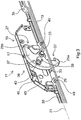
- fitting assembly 11 includes a faceplate 13 and attached to the faceplate 13 storage portion in the form of a closure box 15.
- the closure box 15 is designed specifically for insertion into a recess in a fold of a wing of a window, a door or the like.
- the front housing half 16 of the lock box 15 is omitted in order to illustrate the position of the components located in the lock box 15.
- a locking element 17 is housed in the closure box 15 and mounted by means of a pivot pin 19 about its longitudinal axis 20 pivotally mounted on the closure box 15.
- the longitudinal axis 20 of the pivot pin 19 in this case extends at right angles to the longitudinal axis 21 of the faceplate 13th
- the locking element 17 is executed in the illustrated embodiment of the invention as a plate-shaped component. As shown, it has two hook elements 25a, 25b, which are curved in opposite directions and arranged so that their free ends 27 face each other. In the in Fig. 4 shown pivot position of the locking element 17 are both hook elements 25a, 25b within the lock box 15, wherein no portion of the locking member 17 protrudes beyond the front side 29 of the faceplate 13. Therefore, the hook elements 25a, 25b are both in a release position here.
- each of the hook elements 25a, 25b are pivoted out through a corresponding opening 33 of the faceplate 13 from the closure box 15, as for the left hook member 25a in FIG Fig. 1-3 is shown.
- the hook element 25a an associated closing part (not shown) engage behind, which is arranged on another fitting part, a blend or sash profile or a threshold. That is, the hook element 25a pivoted out of the closure box 15 is in a locking position.
- the right in the image hook element 25b is pivotally in such a locking position and that due to the arrangement of the two hook elements 25a, 25b only one of them can be in the pivoted-out locking position.
- a transfer device 36 is provided with a slide control 37.
- a guide slot in the form of a slot 39 is formed, in which a sliding block 40 is added.
- the sliding block 40 is connected at one of the longitudinal axis 20 of the pivot pin 19 spaced location with a control slide 43 which is mounted along the longitudinal axis 21 of the faceplate 13 slidably in the closure box 15 and coupled to the drive rods 35.
- the spool 43 comprises two parallel control plates 45, between which the locking element 17 is arranged.
- the coupling of the control plates 45 with the drive rods 35 via formed on the end faces of the control plates 45 engagement lugs 47 which engage positively in matching recesses 49 of the drive rods 35.
- the fitting arrangement 11 described above can thus be carried out as a turn-tilt closure, wherein the in Fig. 1-3 shown pivot position of the locking element 17 a closed position of the turn-tilt closure, the in Fig. 4 shown pivot position of the locking element 17 an open position of the turn-tilt closure and that pivot position of the locking element 17, not shown, in which the right hook member 25b is pivoted out of the closure box 15, corresponds to a tilted position of the turn-tilt closure. Both in the closed position and in the tilted position of the corresponding window or door is reliably secured against digging.
Landscapes
- Engineering & Computer Science (AREA)
- Mechanical Engineering (AREA)
- Structural Engineering (AREA)
- Wing Frames And Configurations (AREA)
Claims (14)
- Ensemble de ferrure (11) pour une fenêtre, une porte ou similaire, comportant
une portion de montage (15) réalisée pour la fixation directe ou indirecte sur un cadre dormant ou cadre de vantail de la fenêtre, de la porte ou similaire, et un élément de verrouillage (17) qui est monté sur la portion de montage (15) de façon mobile en pivotement autour d'un axe de pivotement (20), dans lequel
l'élément de verrouillage (17) comprend un premier et un second élément en crochet (25a, 25b) pour engager par l'arrière une partie de fermeture, et l'élément de verrouillage (17) est un crochet double ayant deux pointes de crochet libres (27),
dans une première position de pivotement de l'élément de verrouillage (17), le premier élément en crochet (25a) se situe dans une position de verrouillage pivotée vers l'extérieur,
dans une seconde position de pivotement de l'élément de verrouillage (17), le second élément en crochet (25b) se situe dans une position de verrouillage pivotée vers l'extérieur, et
dans une troisième position de pivotement de l'élément de verrouillage (17), les deux éléments en crochet (25a, 25b) se situent dans une position de libération pivotée vers l'intérieur. - Ensemble de ferrure selon la revendication 1,
caractérisé en ce que
la première position de pivotement et la seconde position de pivotement définissent des positions terminales respectives de la plage de pivotement de l'élément de verrouillage (17), et la troisième position de pivotement se situe entre la première position de pivotement et la seconde position de pivotement. - Ensemble de ferrure selon la revendication 1 ou 2,
caractérisé en ce que
l'ensemble de ferrure (1) est réalisé sous la forme d'une fermeture oscillo-battante, la première position de pivotement de l'élément de verrouillage (17) correspondant à une position fermée de la fermeture oscillo-battante, la seconde position de pivotement de l'élément de verrouillage (17) correspondant à une position basculée de la fermeture oscillo-battante, et la troisième position de pivotement de l'élément de verrouillage (17) correspondant à une position ouverte de la fermeture oscillo-battante. - Ensemble de ferrure selon l'une des revendications précédentes,
caractérisé en ce que
les éléments en crochet (25a, 25b) sont coudés en sens opposés. - Ensemble de ferrure selon l'une des revendications précédentes,
caractérisé en ce que
les extrémités libres (27) des éléments en crochet (25a, 25b) sont dirigées l'une vers l'autre. - Ensemble de ferrure selon l'une des revendications précédentes,
caractérisé en ce que
la portion de montage (15) est agencée sur une têtière (13) qui présente au moins un orifice (33) permettant aux éléments en crochet (25a, 25b) de pivoter vers l'extérieur. - Ensemble de ferrure selon la revendication 6,
caractérisé en ce que
dans la troisième position de pivotement de l'élément de verrouillage (17), aucune portion de celui-ci ne pénètre à travers ledit au moins un orifice (33) de la têtière (13). - Ensemble de ferrure selon la revendication 6 ou 7,
caractérisé en ce que
l'axe de pivotement (20) s'étend à angle droit par rapport à un axe longitudinal (21) de la têtière (13). - Ensemble de ferrure selon l'une des revendications précédentes,
caractérisé par
un poussoir de commande (43) monté de façon mobile en translation linéaire sur la portion de montage (15), et par un moyen de conversion (36) qui est réalisé pour convertir un mouvement de translation du poussoir de commande (43) en un mouvement de pivotement de l'élément de verrouillage (17). - Ensemble de ferrure selon la revendication 9,
caractérisé par
le moyen de conversion (36) comprend une commande à coulisse (37) pourvue d'une coulisse de guidage (39) et d'un coulisseau (40) reçu dans celle-ci, la coulisse de guidage (39) étant réalisée sur l'élément de verrouillage (17) et le coulisseau (40) étant agencé sur le poussoir de commande (43), ou inversement. - Ensemble de ferrure selon la revendication 10,
caractérisé en ce que
le coulisseau (40) est espacé de l'axe de pivotement (20). - Ensemble de ferrure selon l'une des revendications précédentes,
caractérisé en ce que
l'élément de verrouillage (17) est réalisé sous la forme d'une pièce monobloc de préférence en forme de plaque. - Ensemble de ferrure selon l'une des revendications précédentes,
caractérisé en ce que
la portion de montage (15) est réalisée pour être insérée dans une rainure à ferrure de la fenêtre, de la porte ou similaire. - Ensemble de ferrure selon l'une des revendications précédentes,
caractérisé en ce que
la portion de montage (15) est réalisée en forme de boîtier et l'élément de verrouillage (17) est logé dans la portion de montage en forme de boîtier.
Applications Claiming Priority (2)
| Application Number | Priority Date | Filing Date | Title |
|---|---|---|---|
| DE102015120954.3A DE102015120954A1 (de) | 2015-12-02 | 2015-12-02 | Beschlaganordnung |
| PCT/EP2016/079162 WO2017093268A1 (fr) | 2015-12-02 | 2016-11-29 | Ensemble ferrure |
Publications (2)
| Publication Number | Publication Date |
|---|---|
| EP3371397A1 EP3371397A1 (fr) | 2018-09-12 |
| EP3371397B1 true EP3371397B1 (fr) | 2019-11-27 |
Family
ID=57471848
Family Applications (1)
| Application Number | Title | Priority Date | Filing Date |
|---|---|---|---|
| EP16805370.0A Active EP3371397B1 (fr) | 2015-12-02 | 2016-11-29 | Ensemble ferrure |
Country Status (3)
| Country | Link |
|---|---|
| EP (1) | EP3371397B1 (fr) |
| DE (1) | DE102015120954A1 (fr) |
| WO (1) | WO2017093268A1 (fr) |
Families Citing this family (2)
| Publication number | Priority date | Publication date | Assignee | Title |
|---|---|---|---|---|
| DE102017218071A1 (de) | 2017-10-11 | 2019-04-11 | Aug. Winkhaus Gmbh & Co. Kg | Verschluss für einen Treibstangenbeschlag |
| CN109025576A (zh) * | 2018-06-20 | 2018-12-18 | 亚萨合莱国强(山东)五金科技有限公司 | 一种门窗钩形锁点传动器 |
Family Cites Families (5)
| Publication number | Priority date | Publication date | Assignee | Title |
|---|---|---|---|---|
| DE3822343C2 (de) * | 1988-07-01 | 1995-03-16 | Boris Fipke | Zusatz-Sicherheitseinrichtung für Fenster |
| DE10134249A1 (de) * | 2001-07-18 | 2003-01-30 | Roto Frank Ag | Verriegelungsbeschlag mit drehbarer Riegelleiste |
| DE202008009023U1 (de) * | 2008-07-07 | 2009-11-12 | Kfv Karl Fliether Gmbh & Co. Kg | Verschluss für Fenster oder Türen |
| DE102009000746A1 (de) * | 2009-02-10 | 2010-08-12 | Aug. Winkhaus Gmbh & Co. Kg | Verschluss für einen Treibstangenbeschlag |
| DE202011102905U1 (de) * | 2011-07-06 | 2012-10-11 | Maco Technologie Gmbh | Schloss |
-
2015
- 2015-12-02 DE DE102015120954.3A patent/DE102015120954A1/de not_active Withdrawn
-
2016
- 2016-11-29 EP EP16805370.0A patent/EP3371397B1/fr active Active
- 2016-11-29 WO PCT/EP2016/079162 patent/WO2017093268A1/fr not_active Ceased
Non-Patent Citations (1)
| Title |
|---|
| None * |
Also Published As
| Publication number | Publication date |
|---|---|
| WO2017093268A1 (fr) | 2017-06-08 |
| EP3371397A1 (fr) | 2018-09-12 |
| DE102015120954A1 (de) | 2017-06-08 |
Similar Documents
| Publication | Publication Date | Title |
|---|---|---|
| EP0119433B2 (fr) | Ferrure pour un panneau de fenêtre, de porte ou similaire, pouvant au moins basculer et se déplacer d'un plan dans un deuxième plan parallèle | |
| DE102008062950A1 (de) | Beschlag mit ausfahrbarem Verriegelungselement | |
| DE3334298C3 (de) | Verschluß für Fenster, Türen oder dergleichen | |
| WO2017093268A1 (fr) | Ensemble ferrure | |
| EP2143859B1 (fr) | Système de verouillage | |
| DE8711496U1 (de) | Verschluß für zweiflügelige Fenster, Türen od. dgl. | |
| DE102013203488A1 (de) | Öffnungsbegrenzer | |
| EP3215696B1 (fr) | Serrure | |
| EP4174266A1 (fr) | Agencement de battant | |
| DE102014226794A1 (de) | Beschlag zum Einbau zwischen einem Flügel und einem festen Rahmen eines Fensters, einer Tür oder dergleichen sowie Fenster, Tür oder dergleichen mit einem derartigen Beschlag | |
| EP1590548B1 (fr) | Ferrure oscillobattante | |
| DE102004060717B4 (de) | Verschluss zur Verriegelung eines Flügels in einem Rahmen eines Fensters | |
| EP3235988A1 (fr) | Système de fenêtre et/ou système de porte | |
| DE102021115490A1 (de) | Feststellvorrichtung für beidseitig angeschlagene Tür | |
| DE102020112147A1 (de) | Scharnierbaugruppe mit gemeinsamer Betätigung | |
| DE102014117419A1 (de) | Beschlag für Fenster, Türen und dergleichen und Getriebeeinheit für einen solchen Beschlag | |
| EP2320013B1 (fr) | Armature dotée d'une transmission de renvoi | |
| EP3194697B1 (fr) | Ensemble ferrure | |
| DE102014111131A1 (de) | Vorrichtung zur Ver- und Entriegelung eines Fensterflügels, einer Lüftungsklappe oder dergleichen an einem Blendrahmen | |
| EP1790805B1 (fr) | Mécanisme d'actionnement à levier pour une crémone | |
| EP2754795B1 (fr) | Gâche ou serrure à mortaiser | |
| EP2182149B1 (fr) | Dispositif de traction pour ferrure à crémone | |
| DE2457169A1 (de) | Kantenverschluss fuer fenster und tueren | |
| DE102004054979B4 (de) | Fenster, Tür oder dergleichen mit einer flächenhaften Verriegelungseinrichtung | |
| DE69201798T2 (de) | Verriegelungsvorrichtung. |
Legal Events
| Date | Code | Title | Description |
|---|---|---|---|
| STAA | Information on the status of an ep patent application or granted ep patent |
Free format text: STATUS: UNKNOWN |
|
| STAA | Information on the status of an ep patent application or granted ep patent |
Free format text: STATUS: THE INTERNATIONAL PUBLICATION HAS BEEN MADE |
|
| PUAI | Public reference made under article 153(3) epc to a published international application that has entered the european phase |
Free format text: ORIGINAL CODE: 0009012 |
|
| STAA | Information on the status of an ep patent application or granted ep patent |
Free format text: STATUS: REQUEST FOR EXAMINATION WAS MADE |
|
| 17P | Request for examination filed |
Effective date: 20180608 |
|
| AK | Designated contracting states |
Kind code of ref document: A1 Designated state(s): AL AT BE BG CH CY CZ DE DK EE ES FI FR GB GR HR HU IE IS IT LI LT LU LV MC MK MT NL NO PL PT RO RS SE SI SK SM TR |
|
| AX | Request for extension of the european patent |
Extension state: BA ME |
|
| DAV | Request for validation of the european patent (deleted) | ||
| DAX | Request for extension of the european patent (deleted) | ||
| GRAP | Despatch of communication of intention to grant a patent |
Free format text: ORIGINAL CODE: EPIDOSNIGR1 |
|
| STAA | Information on the status of an ep patent application or granted ep patent |
Free format text: STATUS: GRANT OF PATENT IS INTENDED |
|
| GRAJ | Information related to disapproval of communication of intention to grant by the applicant or resumption of examination proceedings by the epo deleted |
Free format text: ORIGINAL CODE: EPIDOSDIGR1 |
|
| STAA | Information on the status of an ep patent application or granted ep patent |
Free format text: STATUS: REQUEST FOR EXAMINATION WAS MADE |
|
| INTG | Intention to grant announced |
Effective date: 20190507 |
|
| GRAP | Despatch of communication of intention to grant a patent |
Free format text: ORIGINAL CODE: EPIDOSNIGR1 |
|
| STAA | Information on the status of an ep patent application or granted ep patent |
Free format text: STATUS: GRANT OF PATENT IS INTENDED |
|
| INTG | Intention to grant announced |
Effective date: 20190613 |
|
| GRAS | Grant fee paid |
Free format text: ORIGINAL CODE: EPIDOSNIGR3 |
|
| GRAA | (expected) grant |
Free format text: ORIGINAL CODE: 0009210 |
|
| STAA | Information on the status of an ep patent application or granted ep patent |
Free format text: STATUS: THE PATENT HAS BEEN GRANTED |
|
| AK | Designated contracting states |
Kind code of ref document: B1 Designated state(s): AL AT BE BG CH CY CZ DE DK EE ES FI FR GB GR HR HU IE IS IT LI LT LU LV MC MK MT NL NO PL PT RO RS SE SI SK SM TR |
|
| REG | Reference to a national code |
Ref country code: GB Ref legal event code: FG4D Free format text: NOT ENGLISH |
|
| REG | Reference to a national code |
Ref country code: CH Ref legal event code: EP |
|
| REG | Reference to a national code |
Ref country code: AT Ref legal event code: REF Ref document number: 1206827 Country of ref document: AT Kind code of ref document: T Effective date: 20191215 |
|
| REG | Reference to a national code |
Ref country code: DE Ref legal event code: R096 Ref document number: 502016007802 Country of ref document: DE |
|
| REG | Reference to a national code |
Ref country code: IE Ref legal event code: FG4D Free format text: LANGUAGE OF EP DOCUMENT: GERMAN |
|
| REG | Reference to a national code |
Ref country code: NL Ref legal event code: MP Effective date: 20191127 |
|
| REG | Reference to a national code |
Ref country code: LT Ref legal event code: MG4D |
|
| PG25 | Lapsed in a contracting state [announced via postgrant information from national office to epo] |
Ref country code: FI Free format text: LAPSE BECAUSE OF FAILURE TO SUBMIT A TRANSLATION OF THE DESCRIPTION OR TO PAY THE FEE WITHIN THE PRESCRIBED TIME-LIMIT Effective date: 20191127 Ref country code: BG Free format text: LAPSE BECAUSE OF FAILURE TO SUBMIT A TRANSLATION OF THE DESCRIPTION OR TO PAY THE FEE WITHIN THE PRESCRIBED TIME-LIMIT Effective date: 20200227 Ref country code: NO Free format text: LAPSE BECAUSE OF FAILURE TO SUBMIT A TRANSLATION OF THE DESCRIPTION OR TO PAY THE FEE WITHIN THE PRESCRIBED TIME-LIMIT Effective date: 20200227 Ref country code: GR Free format text: LAPSE BECAUSE OF FAILURE TO SUBMIT A TRANSLATION OF THE DESCRIPTION OR TO PAY THE FEE WITHIN THE PRESCRIBED TIME-LIMIT Effective date: 20200228 Ref country code: LV Free format text: LAPSE BECAUSE OF FAILURE TO SUBMIT A TRANSLATION OF THE DESCRIPTION OR TO PAY THE FEE WITHIN THE PRESCRIBED TIME-LIMIT Effective date: 20191127 Ref country code: NL Free format text: LAPSE BECAUSE OF FAILURE TO SUBMIT A TRANSLATION OF THE DESCRIPTION OR TO PAY THE FEE WITHIN THE PRESCRIBED TIME-LIMIT Effective date: 20191127 Ref country code: SE Free format text: LAPSE BECAUSE OF FAILURE TO SUBMIT A TRANSLATION OF THE DESCRIPTION OR TO PAY THE FEE WITHIN THE PRESCRIBED TIME-LIMIT Effective date: 20191127 Ref country code: LT Free format text: LAPSE BECAUSE OF FAILURE TO SUBMIT A TRANSLATION OF THE DESCRIPTION OR TO PAY THE FEE WITHIN THE PRESCRIBED TIME-LIMIT Effective date: 20191127 |
|
| PG25 | Lapsed in a contracting state [announced via postgrant information from national office to epo] |
Ref country code: HR Free format text: LAPSE BECAUSE OF FAILURE TO SUBMIT A TRANSLATION OF THE DESCRIPTION OR TO PAY THE FEE WITHIN THE PRESCRIBED TIME-LIMIT Effective date: 20191127 Ref country code: RS Free format text: LAPSE BECAUSE OF FAILURE TO SUBMIT A TRANSLATION OF THE DESCRIPTION OR TO PAY THE FEE WITHIN THE PRESCRIBED TIME-LIMIT Effective date: 20191127 Ref country code: IS Free format text: LAPSE BECAUSE OF FAILURE TO SUBMIT A TRANSLATION OF THE DESCRIPTION OR TO PAY THE FEE WITHIN THE PRESCRIBED TIME-LIMIT Effective date: 20200327 |
|
| PG25 | Lapsed in a contracting state [announced via postgrant information from national office to epo] |
Ref country code: AL Free format text: LAPSE BECAUSE OF FAILURE TO SUBMIT A TRANSLATION OF THE DESCRIPTION OR TO PAY THE FEE WITHIN THE PRESCRIBED TIME-LIMIT Effective date: 20191127 |
|
| REG | Reference to a national code |
Ref country code: CH Ref legal event code: PL |
|
| PG25 | Lapsed in a contracting state [announced via postgrant information from national office to epo] |
Ref country code: DK Free format text: LAPSE BECAUSE OF FAILURE TO SUBMIT A TRANSLATION OF THE DESCRIPTION OR TO PAY THE FEE WITHIN THE PRESCRIBED TIME-LIMIT Effective date: 20191127 Ref country code: CH Free format text: LAPSE BECAUSE OF NON-PAYMENT OF DUE FEES Effective date: 20191130 Ref country code: LI Free format text: LAPSE BECAUSE OF NON-PAYMENT OF DUE FEES Effective date: 20191130 Ref country code: EE Free format text: LAPSE BECAUSE OF FAILURE TO SUBMIT A TRANSLATION OF THE DESCRIPTION OR TO PAY THE FEE WITHIN THE PRESCRIBED TIME-LIMIT Effective date: 20191127 Ref country code: PT Free format text: LAPSE BECAUSE OF FAILURE TO SUBMIT A TRANSLATION OF THE DESCRIPTION OR TO PAY THE FEE WITHIN THE PRESCRIBED TIME-LIMIT Effective date: 20200419 Ref country code: CZ Free format text: LAPSE BECAUSE OF FAILURE TO SUBMIT A TRANSLATION OF THE DESCRIPTION OR TO PAY THE FEE WITHIN THE PRESCRIBED TIME-LIMIT Effective date: 20191127 Ref country code: LU Free format text: LAPSE BECAUSE OF NON-PAYMENT OF DUE FEES Effective date: 20191129 Ref country code: RO Free format text: LAPSE BECAUSE OF FAILURE TO SUBMIT A TRANSLATION OF THE DESCRIPTION OR TO PAY THE FEE WITHIN THE PRESCRIBED TIME-LIMIT Effective date: 20191127 Ref country code: ES Free format text: LAPSE BECAUSE OF FAILURE TO SUBMIT A TRANSLATION OF THE DESCRIPTION OR TO PAY THE FEE WITHIN THE PRESCRIBED TIME-LIMIT Effective date: 20191127 |
|
| REG | Reference to a national code |
Ref country code: BE Ref legal event code: MM Effective date: 20191130 |
|
| REG | Reference to a national code |
Ref country code: DE Ref legal event code: R097 Ref document number: 502016007802 Country of ref document: DE |
|
| PG25 | Lapsed in a contracting state [announced via postgrant information from national office to epo] |
Ref country code: MC Free format text: LAPSE BECAUSE OF FAILURE TO SUBMIT A TRANSLATION OF THE DESCRIPTION OR TO PAY THE FEE WITHIN THE PRESCRIBED TIME-LIMIT Effective date: 20191127 Ref country code: SM Free format text: LAPSE BECAUSE OF FAILURE TO SUBMIT A TRANSLATION OF THE DESCRIPTION OR TO PAY THE FEE WITHIN THE PRESCRIBED TIME-LIMIT Effective date: 20191127 Ref country code: SK Free format text: LAPSE BECAUSE OF FAILURE TO SUBMIT A TRANSLATION OF THE DESCRIPTION OR TO PAY THE FEE WITHIN THE PRESCRIBED TIME-LIMIT Effective date: 20191127 |
|
| PLBE | No opposition filed within time limit |
Free format text: ORIGINAL CODE: 0009261 |
|
| STAA | Information on the status of an ep patent application or granted ep patent |
Free format text: STATUS: NO OPPOSITION FILED WITHIN TIME LIMIT |
|
| PG25 | Lapsed in a contracting state [announced via postgrant information from national office to epo] |
Ref country code: IE Free format text: LAPSE BECAUSE OF NON-PAYMENT OF DUE FEES Effective date: 20191129 |
|
| 26N | No opposition filed |
Effective date: 20200828 |
|
| PG25 | Lapsed in a contracting state [announced via postgrant information from national office to epo] |
Ref country code: PL Free format text: LAPSE BECAUSE OF FAILURE TO SUBMIT A TRANSLATION OF THE DESCRIPTION OR TO PAY THE FEE WITHIN THE PRESCRIBED TIME-LIMIT Effective date: 20191127 Ref country code: BE Free format text: LAPSE BECAUSE OF NON-PAYMENT OF DUE FEES Effective date: 20191130 Ref country code: SI Free format text: LAPSE BECAUSE OF FAILURE TO SUBMIT A TRANSLATION OF THE DESCRIPTION OR TO PAY THE FEE WITHIN THE PRESCRIBED TIME-LIMIT Effective date: 20191127 |
|
| PG25 | Lapsed in a contracting state [announced via postgrant information from national office to epo] |
Ref country code: CY Free format text: LAPSE BECAUSE OF FAILURE TO SUBMIT A TRANSLATION OF THE DESCRIPTION OR TO PAY THE FEE WITHIN THE PRESCRIBED TIME-LIMIT Effective date: 20191127 |
|
| GBPC | Gb: european patent ceased through non-payment of renewal fee |
Effective date: 20201129 |
|
| PG25 | Lapsed in a contracting state [announced via postgrant information from national office to epo] |
Ref country code: HU Free format text: LAPSE BECAUSE OF FAILURE TO SUBMIT A TRANSLATION OF THE DESCRIPTION OR TO PAY THE FEE WITHIN THE PRESCRIBED TIME-LIMIT; INVALID AB INITIO Effective date: 20161129 Ref country code: MT Free format text: LAPSE BECAUSE OF FAILURE TO SUBMIT A TRANSLATION OF THE DESCRIPTION OR TO PAY THE FEE WITHIN THE PRESCRIBED TIME-LIMIT Effective date: 20191127 |
|
| PG25 | Lapsed in a contracting state [announced via postgrant information from national office to epo] |
Ref country code: GB Free format text: LAPSE BECAUSE OF NON-PAYMENT OF DUE FEES Effective date: 20201129 |
|
| PG25 | Lapsed in a contracting state [announced via postgrant information from national office to epo] |
Ref country code: TR Free format text: LAPSE BECAUSE OF FAILURE TO SUBMIT A TRANSLATION OF THE DESCRIPTION OR TO PAY THE FEE WITHIN THE PRESCRIBED TIME-LIMIT Effective date: 20191127 |
|
| PG25 | Lapsed in a contracting state [announced via postgrant information from national office to epo] |
Ref country code: MK Free format text: LAPSE BECAUSE OF FAILURE TO SUBMIT A TRANSLATION OF THE DESCRIPTION OR TO PAY THE FEE WITHIN THE PRESCRIBED TIME-LIMIT Effective date: 20191127 |
|
| PGFP | Annual fee paid to national office [announced via postgrant information from national office to epo] |
Ref country code: DE Payment date: 20251119 Year of fee payment: 10 |
|
| PGFP | Annual fee paid to national office [announced via postgrant information from national office to epo] |
Ref country code: AT Payment date: 20251120 Year of fee payment: 10 |
|
| PGFP | Annual fee paid to national office [announced via postgrant information from national office to epo] |
Ref country code: IT Payment date: 20251125 Year of fee payment: 10 |
|
| PGFP | Annual fee paid to national office [announced via postgrant information from national office to epo] |
Ref country code: FR Payment date: 20251126 Year of fee payment: 10 |