EP3371536B1 - Système de séchage par pulvérisation comprennant une connection améliorée et méthode de nétoyage du système - Google Patents
Système de séchage par pulvérisation comprennant une connection améliorée et méthode de nétoyage du système Download PDFInfo
- Publication number
- EP3371536B1 EP3371536B1 EP15794074.3A EP15794074A EP3371536B1 EP 3371536 B1 EP3371536 B1 EP 3371536B1 EP 15794074 A EP15794074 A EP 15794074A EP 3371536 B1 EP3371536 B1 EP 3371536B1
- Authority
- EP
- European Patent Office
- Prior art keywords
- valve
- conveying line
- cip
- spray drying
- sanitary
- Prior art date
- Legal status (The legal status is an assumption and is not a legal conclusion. Google has not performed a legal analysis and makes no representation as to the accuracy of the status listed.)
- Active
Links
Images




Classifications
-
- F—MECHANICAL ENGINEERING; LIGHTING; HEATING; WEAPONS; BLASTING
- F26—DRYING
- F26B—DRYING SOLID MATERIALS OR OBJECTS BY REMOVING LIQUID THEREFROM
- F26B3/00—Drying solid materials or objects by processes involving the application of heat
- F26B3/02—Drying solid materials or objects by processes involving the application of heat by convection, i.e. heat being conveyed from a heat source to the materials or objects to be dried by a gas or vapour, e.g. air
- F26B3/10—Drying solid materials or objects by processes involving the application of heat by convection, i.e. heat being conveyed from a heat source to the materials or objects to be dried by a gas or vapour, e.g. air the gas or vapour carrying the materials or objects to be dried with it
- F26B3/12—Drying solid materials or objects by processes involving the application of heat by convection, i.e. heat being conveyed from a heat source to the materials or objects to be dried by a gas or vapour, e.g. air the gas or vapour carrying the materials or objects to be dried with it in the form of a spray, i.e. sprayed or dispersed emulsions or suspensions
Definitions
- the present invention relates to a spray drying system comprising a spray dryer with a drying chamber and a process air/gas supply device, at least one powder recovery unit, a conveying line for powdery material such as fines from the powder recovery unit, and means for connecting the conveying line to a cleaning-in-place, CIP, arrangement including a CIP line configured to transport CIP liquid.
- the invention furthermore relates to a method for cleaning a spray drying system.
- WO 2008110623 A2 and JP3096611 B2 disclose spray drying systems.
- Dry methods involve manual sweeping of surfaces in contact with the product, or air or gas sweeping by allowing a high velocity air stream to pass over the surfaces in question.
- Wet methods involve either manual hosing of surfaces or more effectively by use of automated cleaning-in-place systems (CIP systems).
- CIP systems automated cleaning-in-place systems
- the CIP operation is typically controlled by a program which controls pump and valve functions, and cleaning sequences are given the optimum timing for efficient cleaning of all parts of the plant.
- Modern days CIP arrangements are flexible and different washing programs can be selected, just as the program software includes the flexibility to alter and adapt the washing programs according to experience and need when new products are processed, or new operating conditions are applied. Further, individual programs are developed for specific products for which cleaning efficiency, cleaning time or the type and amount of chemicals used can differ.
- CIP arrangements may e.g. use a three-tank system of a four-tank CIP kitchen (the fourth tank is for cleaning the bag filter). It ensures a minimum of idle time when changing from one cleaning solution to another.
- the CIP kitchen is designed to reuse and circulate the rinsing water and cleaning liquids, and with direct or indirect heating of the liquids during the cleaning process. That is, the caustic and acid concentration is measured during circulation and supplemented automatically to achieve optimum concentration.
- the CIP supply line is equipped with remote operated valves and CIP supply pumps.
- the return line is equipped with conductivity probes and remote operated valves for routing the caustic, acid and water to each tank or drain.
- the complex nature of the cleaning regimen is particularly pronounced in spray drying systems comprising conveying lines for transporting powdery material from powdery recovery units such as cyclones and bag filters downstream of the drying chamber to upstream units such as the drying chamber itself or to a finishing treatment unit such as a VIBRO-FLUIDIZERTM or fluid bed for handling the material discharged from the drying chamber.
- conveying lines are configured to transport powdery material in the form of fines (the smallest fraction of a powder product), i.e. a so-called fines return system, during normal operation.
- the transfer device connecting the powder recovery unit to the conveying line and the conveying line In order to clean the powder recovery unit itself, the transfer device connecting the powder recovery unit to the conveying line and the conveying line, the pipe work to the relevant parts is disconnected from the product line, and connected to the CIP arrangement instead to allow the CIP liquid to flush the transfer device, the powder recovery unit itself and adjacent pipe work.
- the conveying line for the stream of powder is thoroughly dried by air/gas to ensure that the stream of powder in the conveying line is not compromised by any remains of moisture.
- the cleaning regimen for spray drying systems comprising such return conveying lines is often time consuming, as it has hitherto been the practice to manually disconnect some parts of the spray drying system from the production line and to connect these parts to a cleaning system.
- a risk of contamination is present, as cleaned parts will be exposed to the outside surrounding air and environment in the time period between being disconnected from the cleaning system and until being connected to the production line again.
- the CIP arrangement often also includes flexible hoses to ease the conversion from operation mode to CIP mode and vice versa; however, such flexible hoses involve a risk of sacking leaving an amount of liquid behind in a non-drainable pocket.
- great care must be shown in order to ensure that the couplings connecting the CIP line with the conveying line portion through the transfer device and/or the powder recovery unit and any accessory equipment are tight such that no leakage of CIP liquids occurs.
- a spray drying system of the kind mentioned in the introduction which is furthermore characterized in that said connecting means comprise a connection assembly including at least one sanitary valve including a first inlet to the conveying line, and a valve member moveable between an open position and a closed position, wherein in the closed position, one part of the valve member seals the conveying line and when in the open position, the valve member is moved to provide communication between the CIP line and the conveying line, thereby allowing CIP liquid to enter or exit the sanitary valve connecting the CIP line and the conveying line via said first inlet.
- said connecting means comprise a connection assembly including at least one sanitary valve including a first inlet to the conveying line, and a valve member moveable between an open position and a closed position, wherein in the closed position, one part of the valve member seals the conveying line and when in the open position, the valve member is moved to provide communication between the CIP line and the conveying line, thereby allowing CIP liquid to enter or exit the sanitary valve connecting the CIP line and the convey
- a sanitary valve makes it possible to establish a connection between the CIP line and the conveying line at any time, also in the operation mode of the system. Hence, the CIP procedure may be performed without disconnecting any parts from the spray drying system. Thus, no contaminants can enter from the surrounding environment, in the time periods during conversion from CIP mode and normal operation.
- Another advantage provided by the sanitary valve is that it reduces the manual labour required by an operator in the traditional systems, where manual disconnection and reconnection of parts of the spray drying system is needed, whenever a CIP procedure is required. As such the spray drying system can be in normal operation for a higher percentage of time, thus resulting in a higher capacity of the spray dryer.
- the spray drying system is more secure in that no contaminants can enter the conveying line, just as there are no disconnection and reconnection of couplings that could give rise to leakage of CIP liquid.
- the system may be remote operated or automated, such that an operator is only required to switch between CIP and normal operation. This will reduce the downtime of the process line even further.
- valves between the CIP system and spray drying system have previously been a prejudice in the field against having valves between the CIP system and spray drying system, as if not separated in full may mean a risk of contamination of the spray dried product.
- One reason being that existing valves are designed for either powder or liquid or gas but are not suitable of all three elements.
- sanitary within the field entails that such sanitary valves are designed to meet the stringent demands of various authorizations in dependence of governing bodies.
- sanitary is meant that the equipment should comply with relevant regulations, among other AAA (US) and/or EHEDG (EU) guidelines.
- the sanitary requirements entail that relevant parts of the valve are designed such and are made from polished, stainless steel or suitable polymers to ensure efficient cleaning and sanitizing, with a very limited risk of residues of material and/or cleaning fluids.
- the sanitary valve is a sanitary plug valve, in which said one part of the valve member is constituted by a plug end to seal the conveying line in the closed position and to be moved by retraction to attain the open position.
- a plug end to seal the conveying line in the closed position and to be moved by retraction to attain the open position.
- valves may be used instead of the plug valve as long as it is possible to fulfil the sanitary requirements.
- suitable valves include ball valve, ball segment valve, butterfly valve, knife valve, and gate valve.
- an inner surface of the plug end of the valve member, which engages the conveying line has the same shape as the conveying line.
- the conveying line has the shape of a cylinder, and as such, the plug end of the valve member has a curvature corresponding to the inner diameter of the cylindrical conveying line.
- a seal is provided on the plug end of the valve member, such that when the valve is in its closed position, an air/gas tight seal is formed between the valve and the conveying line. This seal ensures that no contamination can enter the system from the outside environment or from the CIP line, during normal operation, when the valve is in its closed position.
- a gap is formed between a side surface of the plug end of the valve member and the conveying line, where the gap is formed in a position between the conveying line and the CIP line, when the valve is in its closed position.
- the sanitary plug valve comprises both a seal, which in the valves closed position forms an air/gas tight seal between the plug end of the valve member and the conveying line, and a gap, between the plug end of the valve and the conveying line, such that contaminants are prohibited from entering from the outside environment or the CIP system through the sanitary plug valve, but at the same time, any edges of the plug end, entering the conveying line, can be avoided when the valve is in the closed position.
- the gap continues through at least a part of the plug end, such that a canal is formed.
- clean purge air/gas can be blown through the gap, when the valve is in its closed position, such that the material in the conveying line cannot enter said gap.
- This is achieved by blowing purge air/gas through the canal and gap, at a higher pressure, than the pressure in the conveying line.
- a method for cleaning a spray drying system of the type described above comprises the steps of:
- This method ensures that the spray drying system does not have to be disassembled during the process of converting from production to CIP, during the CIP procedure, or during the conversion back to normal operation. This reduces the risk of contamination entering the spray drying system, as parts are not exposed to the dirty outside environment.
- the method comprises blowing purge air/gas through the sanitary plug valve, when the valve is in its closed position, in order to prevent the material in the conveying line to enter the plug valve.
- the air/gas used to dry the system after cleaning is supplied from the spray dryer process air/gas supply. During normal operation, this air/gas would be used in the spray dryer system or for the after-drying unit(s). This reduces the costs of the CIP system using the heater and pump systems, which are already included in the spray drying system.
- the method is automatic when initiated and completed according to the above described embodiments of the invention.
- the CIP procedure may be initiated or planned based on a response from sensors in the system or from regulatory demands.
- Fig. 1 shows a schematic view of the main components of a spray drying system 1.
- the spray drying system 1 comprises a spray dryer with a drying chamber 2 and a process air/gas supply device 3, typically including an air/gas disperser.
- gas will be used alongside with the term “air” as “air/gas” and is to be interpreted as encompassing any gas that is suitable as process gas in such a spray drying system.
- the drying chamber 2 also incorporates atomizing means, such as nozzles and/or an atomizer wheel.
- an outlet 5 for dried material is provided at the lower end of the drying chamber 2.
- an after-treatment unit in the form of vibrating or static fluid bed 6 is provided. At one end, the vibrating or static fluid bed 6 receives dried material from the outlet 5 of the drying chamber 2 for further treatment of the material, which is then to be collected at an outlet at the other end of the vibrating or static fluid bed. Further downstream equipment may be present as well, but is not relevant to the present invention.
- the spray drying system 1 comprises at least one powder recovery unit 4, to which spent process air/gas with particles entrained in the process air/gas is conducted via exhaust line 7.
- the powder recovery units 4 may take the form of cyclones or bag filters, or any combination thereof.
- a conveying line 11 is provided for transporting the powdery material recovered in the powder recovery unit 4 to upstream equipment such as the drying chamber 2 itself, at an arbitrary position, or to the vibrating or static fluid bed 6, likewise to an arbitrary position.
- the recovered material is in the form of fines, which are powdery material of satisfying composition but of a size and/or configuration that needs further processing in order to fulfil quality requirements.
- the position of introduction of the fines return into the upstream units typically depends on the size and/or configuration of the material and of the prevailing operating conditions in the drying chamber 2 and the vibrating fluidizer 6.
- a divert valve 9 is present in the system as well in order to ensure proper distribution of the returning fines.
- a transfer device 70 is provided for providing transfer of the powder from the powder recovery unit 4 to the conveying line 11.
- a transfer device is typically constituted by a rotating valve (i.e. a blow through rotary valve or a drop through rotary valve with a feeding shoe) allowing blow-through of air/gas to ensure transport of the fines in the conveying line.
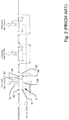
- connection assembly 10 of the spray drying system 1 according to the invention will be described. It is noted that only those parts of the spray drying system including the CIP arrangement according to the invention that are different from the prior art spray drying system 1 including the CIP arrangement 8 shown in Fig. 2 will be described in detail.
- the connection assembly 10 comprises a sanitary valve of a suitable kind.
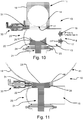
- the sanitary valve is a sanitary plug valve 20 including a first inlet 12 to the conveying line 11 and a valve member 21 moveable between an open position and a closed position, wherein in the closed position, a plug end 22 of the valve member 21 seals the conveying line 11 and when in the open position, the valve member 21 is retracted to provide communication between the CIP line 15 and the conveying line 11.
- CIP liquid from a CIP supply 16 is allowed to enter the sanitary plug valve 20 through the CIP line 15 and into the conveying line 11 via said first inlet 12, and exit to a CIP drain 17 through the CIP line 15.
- the sanitary valve 20 may be formed and/or used as a two- or three-way valve, or even more ways, having two or more working conditions including an unactuated condition and one or more actuated conditions. Adaptation of the sanitary valve to provide the required number and configuration of ports and passageways lies within the competence of the skilled person.
- an inner surface 23 of the valve member plug end 22, which engages the conveying line 11, has the same shape as an inner surface 14 of the conveying line 11.
- the inner surface 23 is formed as a part-cylindrical surface, adapting to the cylinder shape of the conveying line 11.
- a seal 24 is provided between the valve member 21 and the conveying line 11, namely in the embodiment shown between a side surface 26 of the valve member plug end 22 and a wall 18 surrounding the conveying line 11.
- the conveying line 11 itself and the surrounding wall 18 may in principle take any suitable form other than the shown cylindrical conveying line 11 and the rectangular wall 18.
- a drop tube 41 of the powder recovery unit (not shown) is connected to the connection assembly 10.
- the inner surface of the valve member plug end 22 is formed in accordance with an inner surface 44 of the drop tube 41.
- the dimensions of the sanitary plug valve 20 are chosen such that a gap 25 is formed between the side surface 26 of the valve member plug end 22 and the wall 18 surrounding the conveying line 11 when the valve member 21 is in its closed position. At the end of the gap 25 facing the conveying line 11, a second inlet 13 is formed.
- the gap 25 extends from the seal 24 up to the second inlet 13 into the conveying line 11.
- a flushing valve 30 is connected to the conveying line 11.
- the flushing valve is provided with an inlet 31 for process air/gas in order to introduce the air/gas into the conveying line 11.
- the position of the flushing valve 30 is in close proximity to the conveying line 11 in the preferred embodiment.
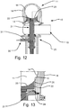
- Figs 12 to 14 illustrate a different position of the entry of process air/gas.
- the flushing valve 30 is in fluid connection with the conveying line 11 via the gap 25, i.e. also in the closed condition of the sanitary plug valve 20, when the position of the valve member 21 is as shown in Fig. 8 , air/gas may be introduced into the conveying line 11 through the second inlet 13.
- a sanitary valve 20 is provided at several positions in the spray drying system 1. While the reading of the drawing including any symbols will be immediately apparent to the person skilled in the art, only four of these sanitary valves are marked by reference numeral 20 to be described in the following (from left to right in Fig. 6 ):
- the sanitary valve 20 is a three-way valve, but with another flow path configuration.
- sanitary valves may be present as well in the spray drying system.
- Initiation of the CIP procedure will be determined either according to a pre-defined schedule or programmed to start automatically. Up to this point, normal operation proceeds and the sanitary valve 20 is in a closed position.
- the sanitary valve 20 is moved from the closed position to the open position.
- communication between the CIP line 15 and the conveying line 11 is provided. Referring to the above-mentioned description of Fig. 6 , this corresponds to a sanitary valve as described in relation to the second position.
- CIP liquid is supplied from CIP supply 16 through the CIP line 15 to the sanitary plug valve 20, which is now in the open position.
- CIP liquid from CIP supply 16 is allowed to enter the sanitary valve 20 and flow into the conveying line 11 via the first inlet 12.
- CIP liquid is also supplied to the powder recovery unit 4 through another line, not shown.
- the cyclone, bag filter or other powder recovery unit is supplied with CIP liquid at the top.
- the CIP liquid is drained from the system. Drainage of the conveying line 11 takes place via the first inlet 12 of the sanitary plug valve 20 in that CIP liquid is allowed to exit from the conveying line 11 through CIP line 15 and further to CIP drain 17.
- CIP liquid from the powder recovery unit 4 is drained both through the transfer device 70 and further through the sanitary valve 20 at the second position, and the sanitary valve 20 at the above-mentioned first position.
- air/gas is blown through the respective sanitary valve 20 in order to dry the system.
- the air/gas may be of any suitable composition and temperature, but will typically be heated air/gas.
- the sanitary valve is moved to the closed position and as a final step, normal operation is restarted.
- the air/gas used to dry the system after cleaning is preferably supplied from the process air/gas supply of the spray dryer. As this air/gas would be used to dry out the cyclone or cyclones, or other powder recovery unit(s) in any event, savings on the overall energy are achieved as no separate heating unit for the air/gas to dry the system is needed.
- the process of the inventive method may be carried out automatically from the first to last step.
Landscapes
- Engineering & Computer Science (AREA)
- Life Sciences & Earth Sciences (AREA)
- Microbiology (AREA)
- Mechanical Engineering (AREA)
- General Engineering & Computer Science (AREA)
- Lift Valve (AREA)
- Drying Of Solid Materials (AREA)
- Apparatus For Disinfection Or Sterilisation (AREA)
- Nozzles (AREA)
Claims (12)
- Système de séchage par pulvérisation (1), comprenant :un sécheur par pulvérisation avec une chambre de séchage (2) et un dispositif d'alimentation en air/gaz de traitement (3),au moins une unité de récupération de poudre (4),une ligne de transport (11) pour de la matière en poudre telle que des particules fines provenant de l'unité de récupération de poudre (4), etdes moyens pour connecter la ligne de transport (11) à un agencement de nettoyage sur place, CIP, (8) incluant une ligne de CIP (15) configurée pour transporter du liquide de CIP,caractérisé en ce quelesdits moyens de connexion comprennent un ensemble de connexion (10) comportant au moins une vanne sanitaire (20) incluant une première entrée (12) vers la ligne de transport (11), et un organe de vanne (21) déplaçable entre une position ouverte et une position fermée, où, dans la position fermée, une partie (22) de l'organe de vanne (21) scelle la ligne de transport (11) et dans la position ouverte, l'organe de vanne (21) est déplacé pour assurer la communication entre la ligne de CIP (15) et la ligne de transport (11), pour ainsi permettre à du liquide de CIP d'entrer ou de sortir dans ou hors de la vanne sanitaire (20) reliant la ligne de CIP (15) et la ligne de transport (11) par le biais de ladite première entrée (12).
- Système de séchage par pulvérisation selon la revendication 1, dans lequel la vanne sanitaire est une vanne à boisseau sanitaire (20) dans laquelle ladite une partie de l'organe de vanne est constituée par une extrémité de boisseau (22) prévue pour sceller la ligne de transport (11) dans la position fermée et pour être déplacée par rétraction afin d'atteindre la position ouverte.
- Système de séchage par pulvérisation selon la revendication 2, dans lequel une surface interne (23) de l'extrémité de boisseau (22) de l'organe de vanne qui vient en prise avec la ligne de transport (11) a la même forme qu'une surface interne (14) de la ligne de transport (11), de préférence a la forme d'une surface cylindrique.
- Système de séchage par pulvérisation selon l'une quelconque des revendications 2 et 3, dans lequel un joint (24) est prévu entre l'organe de vanne (21) et la ligne de transport (11), de préférence entre une surface latérale (26) de l'extrémité de boisseau (22) de l'organe de vanne et une paroi (18) entourant la ligne de transport (11).
- Système de séchage par pulvérisation selon la revendication 4, dans lequel un espace (25) est formé entre la surface latérale (26) de l'extrémité de boisseau (22) de l'organe de vanne et la paroi (18) entourant la ligne de transport (11) lorsque l'organe de vanne (21) est dans sa position fermée, et dans lequel une deuxième entrée (13) vers la ligne de transport est prévue au niveau de l'extrémité de l'espace (25).
- Système de séchage par pulvérisation selon les revendications 4 et 5, dans lequel ledit espace (25) s'étend entre le joint (24) et la deuxième entrée (13) vers la ligne de transport (11).
- Système de séchage par pulvérisation selon l'une quelconque des revendications précédentes, dans lequel une vanne de rinçage (30) est connectée à la ligne de transport (11).
- Système de séchage par pulvérisation selon les revendications 5, 6 et 7, dans lequel la vanne de rinçage (30) est en connexion fluidique avec la ligne de transport (11) par le biais dudit espace (25) pour introduire de l'air/du gaz de purge à travers la deuxième entrée (13).
- Procédé de nettoyage d'un système de séchage par pulvérisation selon l'une quelconque des revendications 1 à 8, dans lequel la vanne sanitaire est dans une position fermée lorsque le système fonctionne normalement, le procédé comprenant les étapes suivantes :déterminer qu'une procédure de CIP doit être commencée,déplacer la vanne sanitaire de la position fermée à la position ouverte,fournir du liquide de CIP à travers la ligne de CIP jusqu'à la vanne sanitaire dans la position ouverte,après l'achèvement de la procédure de CIP du système, le liquide de CIP est drainé du système,de l'air/du gaz est soufflé à travers la vanne sanitaire afin de sécher le système,la vanne sanitaire est déplacée dans la position fermée,le fonctionnement normal reprend.
- Procédé de nettoyage d'un système de séchage par pulvérisation selon la revendication 9, dans lequel, au cours du fonctionnement normal, de l'air/du gaz de purge est soufflé à travers la vanne sanitaire afin d'empêcher que la matière de la ligne de transport ne pénètre à l'intérieur de la vanne à boisseau.
- Procédé selon la revendication 9 ou 10, dans lequel l'air/le gaz utilisé pour sécher le système après le nettoyage est fourni à partir de l'alimentation d'air/de gaz de traitement du sécheur par pulvérisation.
- Procédé selon l'une quelconque des revendications 9 à 11, dans lequel le processus, de la première à la dernière étape, est effectué automatiquement.
Priority Applications (1)
| Application Number | Priority Date | Filing Date | Title |
|---|---|---|---|
| PL15794074T PL3371536T3 (pl) | 2015-11-03 | 2015-11-03 | System suszenia rozpyłowego obejmujący ulepszony zespół łączący i sposób czyszczenia systemu |
Applications Claiming Priority (1)
| Application Number | Priority Date | Filing Date | Title |
|---|---|---|---|
| PCT/DK2015/050334 WO2017076411A1 (fr) | 2015-11-03 | 2015-11-03 | Système de séchage par pulvérisation comprenant un ensemble de raccordement amélioré et procédé de nettoyage du système |
Publications (2)
| Publication Number | Publication Date |
|---|---|
| EP3371536A1 EP3371536A1 (fr) | 2018-09-12 |
| EP3371536B1 true EP3371536B1 (fr) | 2019-10-23 |
Family
ID=54540781
Family Applications (1)
| Application Number | Title | Priority Date | Filing Date |
|---|---|---|---|
| EP15794074.3A Active EP3371536B1 (fr) | 2015-11-03 | 2015-11-03 | Système de séchage par pulvérisation comprennant une connection améliorée et méthode de nétoyage du système |
Country Status (6)
| Country | Link |
|---|---|
| EP (1) | EP3371536B1 (fr) |
| CN (1) | CN108291772B (fr) |
| AU (1) | AU2015413693B2 (fr) |
| DK (1) | DK3371536T3 (fr) |
| PL (1) | PL3371536T3 (fr) |
| WO (1) | WO2017076411A1 (fr) |
Families Citing this family (4)
| Publication number | Priority date | Publication date | Assignee | Title |
|---|---|---|---|---|
| WO2022017856A1 (fr) | 2020-07-21 | 2022-01-27 | Gea Tuchenhagen Gmbh | Ensemble soupape |
| CN112221176A (zh) * | 2020-10-28 | 2021-01-15 | 黑龙江广亿达乳业科技有限公司 | 一种乳粉喷雾干燥机的卫生型收粉系统 |
| CN112556328A (zh) * | 2020-11-26 | 2021-03-26 | 安徽荷金来农业发展股份有限公司 | 一种用于牛肉生产的高效烘干装置 |
| WO2025133311A1 (fr) | 2023-12-22 | 2025-06-26 | Gea Process Engineering A/S | Procédés de traitement d'un perméat issu d'un processus de production de concentré de protéine de lait et poudre contenant un perméat ainsi obtenue |
Family Cites Families (8)
| Publication number | Priority date | Publication date | Assignee | Title |
|---|---|---|---|---|
| DK0572356T3 (da) * | 1992-05-26 | 1997-04-21 | Niro Aeromatic Ag | Indretning og fremgangsmåde til vådrensning af filterpatroner i hvirvellagsapparater, spraytørrere og fluidbed anlæg |
| JP3096611B2 (ja) * | 1995-04-28 | 2000-10-10 | 藤崎電機株式会社 | 噴霧乾燥及び流動造粒用装置 |
| WO2000074835A1 (fr) * | 1999-06-08 | 2000-12-14 | Niro A/S | Procede de spray et equipement correspondant |
| US7625537B2 (en) * | 2006-06-12 | 2009-12-01 | Alstom Technology Ltd | Integrated dry and wet flue gas cleaning process and system |
| EP2125154A2 (fr) * | 2007-03-15 | 2009-12-02 | Janssen Pharmaceutica, N.V. | Ensemble de filtre contenant des éléments filtrants en fibre métallique |
| DK2158029T3 (da) * | 2007-04-10 | 2019-08-19 | Gea Process Eng Inc | Procesgasfilter og fremgangsmåde til rensning af dette |
| DK2457049T3 (en) * | 2009-07-20 | 2017-03-20 | Gea Process Eng As | Process for drying a liquid or wet product, and drying apparatus for carrying out the process. |
| EP2632580A2 (fr) * | 2010-10-29 | 2013-09-04 | Velico Medical, Inc. | Système et procédé de séchage par atomisation d'un liquide |
-
2015
- 2015-11-03 PL PL15794074T patent/PL3371536T3/pl unknown
- 2015-11-03 DK DK15794074.3T patent/DK3371536T3/da active
- 2015-11-03 WO PCT/DK2015/050334 patent/WO2017076411A1/fr not_active Ceased
- 2015-11-03 AU AU2015413693A patent/AU2015413693B2/en active Active
- 2015-11-03 EP EP15794074.3A patent/EP3371536B1/fr active Active
- 2015-11-03 CN CN201580084868.7A patent/CN108291772B/zh active Active
Non-Patent Citations (1)
| Title |
|---|
| None * |
Also Published As
| Publication number | Publication date |
|---|---|
| AU2015413693A1 (en) | 2018-05-24 |
| CN108291772A (zh) | 2018-07-17 |
| CN108291772B (zh) | 2020-06-09 |
| EP3371536A1 (fr) | 2018-09-12 |
| DK3371536T3 (da) | 2020-01-06 |
| AU2015413693B2 (en) | 2021-06-24 |
| WO2017076411A1 (fr) | 2017-05-11 |
| NZ742309A (en) | 2022-12-23 |
| PL3371536T3 (pl) | 2020-04-30 |
Similar Documents
| Publication | Publication Date | Title |
|---|---|---|
| EP3371536B1 (fr) | Système de séchage par pulvérisation comprennant une connection améliorée et méthode de nétoyage du système | |
| CN102671884B (zh) | 洗涤机器及其对应洗涤方法 | |
| CN107520209A (zh) | 一种cip在线清洗系统 | |
| CN103962333B (zh) | 一种通过式喷淋清洗机及其清洗方法 | |
| EP3472500B1 (fr) | Vanne de dérivation sanitaire, système de séchage comportant un ensemble vanne amélioré comprenant une telle vanne, et procédé de nettoyage du système | |
| CN205762817U (zh) | 一种cip在线清洗系统 | |
| CN1972621A (zh) | 传送带式餐具清洗机及其运行方法 | |
| CN105731078A (zh) | 蝶阀、由多个蝶阀组成的无菌粉体输送装置及其使用方法 | |
| CN106415182A (zh) | 用于从工业设备中流出的液体中回收热量的装置 | |
| CN104352209A (zh) | 传送带式餐具清洗机及其运行方法 | |
| DK201570712A1 (en) | Spray drying system including an improved connection assembly and method of cleaning the system | |
| CN109068932A (zh) | 用于清洗待洗器皿的传送式洗碗机 | |
| CN208555357U (zh) | 一种污泥干化除臭管道防堵装置 | |
| CN102692910A (zh) | 一种原料血浆袋循环保温清洁融浆在线控制装置 | |
| Stewart et al. | Clean in place | |
| Seiberling et al. | Engineering considerations for CIP/SIP systems | |
| CN1972620A (zh) | 传送带式餐具清洗机及其运行方法 | |
| CN110788047B (zh) | 一种用于胶塞清洗机的无菌转运系统及转运方法 | |
| CN206854308U (zh) | 中间罐喷淋系统 | |
| CN204297690U (zh) | 一种蝶阀及由多个蝶阀组成的无菌粉体输送装置 | |
| EP4549039A1 (fr) | Nettoyage d'un condenseur dans un système de traitement thermique d'aliments liquides | |
| CN223823381U (zh) | 一种鲜奶分配系统 | |
| CN214133145U (zh) | 配制送液系统内壁的残留水及冷凝水去除装置 | |
| DK201670442A1 (en) | Sanitary diverter valve, drying system including an improved valve assembly including such a valve, and method of cleaning the system | |
| CN121588523A (zh) | 一种固体颗粒脱离回收系统及脱离回收方法 |
Legal Events
| Date | Code | Title | Description |
|---|---|---|---|
| STAA | Information on the status of an ep patent application or granted ep patent |
Free format text: STATUS: THE INTERNATIONAL PUBLICATION HAS BEEN MADE |
|
| PUAI | Public reference made under article 153(3) epc to a published international application that has entered the european phase |
Free format text: ORIGINAL CODE: 0009012 |
|
| STAA | Information on the status of an ep patent application or granted ep patent |
Free format text: STATUS: REQUEST FOR EXAMINATION WAS MADE |
|
| 17P | Request for examination filed |
Effective date: 20180516 |
|
| AK | Designated contracting states |
Kind code of ref document: A1 Designated state(s): AL AT BE BG CH CY CZ DE DK EE ES FI FR GB GR HR HU IE IS IT LI LT LU LV MC MK MT NL NO PL PT RO RS SE SI SK SM TR |
|
| AX | Request for extension of the european patent |
Extension state: BA ME |
|
| DAV | Request for validation of the european patent (deleted) | ||
| DAX | Request for extension of the european patent (deleted) | ||
| GRAP | Despatch of communication of intention to grant a patent |
Free format text: ORIGINAL CODE: EPIDOSNIGR1 |
|
| STAA | Information on the status of an ep patent application or granted ep patent |
Free format text: STATUS: GRANT OF PATENT IS INTENDED |
|
| INTG | Intention to grant announced |
Effective date: 20190522 |
|
| GRAS | Grant fee paid |
Free format text: ORIGINAL CODE: EPIDOSNIGR3 |
|
| GRAA | (expected) grant |
Free format text: ORIGINAL CODE: 0009210 |
|
| STAA | Information on the status of an ep patent application or granted ep patent |
Free format text: STATUS: THE PATENT HAS BEEN GRANTED |
|
| AK | Designated contracting states |
Kind code of ref document: B1 Designated state(s): AL AT BE BG CH CY CZ DE DK EE ES FI FR GB GR HR HU IE IS IT LI LT LU LV MC MK MT NL NO PL PT RO RS SE SI SK SM TR |
|
| REG | Reference to a national code |
Ref country code: GB Ref legal event code: FG4D |
|
| REG | Reference to a national code |
Ref country code: CH Ref legal event code: EP |
|
| REG | Reference to a national code |
Ref country code: IE Ref legal event code: FG4D |
|
| REG | Reference to a national code |
Ref country code: DE Ref legal event code: R096 Ref document number: 602015040388 Country of ref document: DE |
|
| REG | Reference to a national code |
Ref country code: AT Ref legal event code: REF Ref document number: 1194109 Country of ref document: AT Kind code of ref document: T Effective date: 20191115 |
|
| REG | Reference to a national code |
Ref country code: SE Ref legal event code: TRGR |
|
| REG | Reference to a national code |
Ref country code: DK Ref legal event code: T3 Effective date: 20191219 |
|
| REG | Reference to a national code |
Ref country code: NL Ref legal event code: FP |
|
| REG | Reference to a national code |
Ref country code: LT Ref legal event code: MG4D |
|
| PG25 | Lapsed in a contracting state [announced via postgrant information from national office to epo] |
Ref country code: PT Free format text: LAPSE BECAUSE OF FAILURE TO SUBMIT A TRANSLATION OF THE DESCRIPTION OR TO PAY THE FEE WITHIN THE PRESCRIBED TIME-LIMIT Effective date: 20200224 Ref country code: BG Free format text: LAPSE BECAUSE OF FAILURE TO SUBMIT A TRANSLATION OF THE DESCRIPTION OR TO PAY THE FEE WITHIN THE PRESCRIBED TIME-LIMIT Effective date: 20200123 Ref country code: NO Free format text: LAPSE BECAUSE OF FAILURE TO SUBMIT A TRANSLATION OF THE DESCRIPTION OR TO PAY THE FEE WITHIN THE PRESCRIBED TIME-LIMIT Effective date: 20200123 Ref country code: LT Free format text: LAPSE BECAUSE OF FAILURE TO SUBMIT A TRANSLATION OF THE DESCRIPTION OR TO PAY THE FEE WITHIN THE PRESCRIBED TIME-LIMIT Effective date: 20191023 Ref country code: GR Free format text: LAPSE BECAUSE OF FAILURE TO SUBMIT A TRANSLATION OF THE DESCRIPTION OR TO PAY THE FEE WITHIN THE PRESCRIBED TIME-LIMIT Effective date: 20200124 Ref country code: LV Free format text: LAPSE BECAUSE OF FAILURE TO SUBMIT A TRANSLATION OF THE DESCRIPTION OR TO PAY THE FEE WITHIN THE PRESCRIBED TIME-LIMIT Effective date: 20191023 |
|
| PG25 | Lapsed in a contracting state [announced via postgrant information from national office to epo] |
Ref country code: RS Free format text: LAPSE BECAUSE OF FAILURE TO SUBMIT A TRANSLATION OF THE DESCRIPTION OR TO PAY THE FEE WITHIN THE PRESCRIBED TIME-LIMIT Effective date: 20191023 Ref country code: IS Free format text: LAPSE BECAUSE OF FAILURE TO SUBMIT A TRANSLATION OF THE DESCRIPTION OR TO PAY THE FEE WITHIN THE PRESCRIBED TIME-LIMIT Effective date: 20200224 Ref country code: HR Free format text: LAPSE BECAUSE OF FAILURE TO SUBMIT A TRANSLATION OF THE DESCRIPTION OR TO PAY THE FEE WITHIN THE PRESCRIBED TIME-LIMIT Effective date: 20191023 |
|
| PG25 | Lapsed in a contracting state [announced via postgrant information from national office to epo] |
Ref country code: AL Free format text: LAPSE BECAUSE OF FAILURE TO SUBMIT A TRANSLATION OF THE DESCRIPTION OR TO PAY THE FEE WITHIN THE PRESCRIBED TIME-LIMIT Effective date: 20191023 |
|
| REG | Reference to a national code |
Ref country code: DE Ref legal event code: R097 Ref document number: 602015040388 Country of ref document: DE |
|
| PG2D | Information on lapse in contracting state deleted |
Ref country code: IS |
|
| PG25 | Lapsed in a contracting state [announced via postgrant information from national office to epo] |
Ref country code: RO Free format text: LAPSE BECAUSE OF FAILURE TO SUBMIT A TRANSLATION OF THE DESCRIPTION OR TO PAY THE FEE WITHIN THE PRESCRIBED TIME-LIMIT Effective date: 20191023 Ref country code: ES Free format text: LAPSE BECAUSE OF FAILURE TO SUBMIT A TRANSLATION OF THE DESCRIPTION OR TO PAY THE FEE WITHIN THE PRESCRIBED TIME-LIMIT Effective date: 20191023 Ref country code: CZ Free format text: LAPSE BECAUSE OF FAILURE TO SUBMIT A TRANSLATION OF THE DESCRIPTION OR TO PAY THE FEE WITHIN THE PRESCRIBED TIME-LIMIT Effective date: 20191023 Ref country code: LU Free format text: LAPSE BECAUSE OF NON-PAYMENT OF DUE FEES Effective date: 20191103 Ref country code: MC Free format text: LAPSE BECAUSE OF FAILURE TO SUBMIT A TRANSLATION OF THE DESCRIPTION OR TO PAY THE FEE WITHIN THE PRESCRIBED TIME-LIMIT Effective date: 20191023 Ref country code: EE Free format text: LAPSE BECAUSE OF FAILURE TO SUBMIT A TRANSLATION OF THE DESCRIPTION OR TO PAY THE FEE WITHIN THE PRESCRIBED TIME-LIMIT Effective date: 20191023 Ref country code: IS Free format text: LAPSE BECAUSE OF FAILURE TO SUBMIT A TRANSLATION OF THE DESCRIPTION OR TO PAY THE FEE WITHIN THE PRESCRIBED TIME-LIMIT Effective date: 20200223 |
|
| REG | Reference to a national code |
Ref country code: AT Ref legal event code: MK05 Ref document number: 1194109 Country of ref document: AT Kind code of ref document: T Effective date: 20191023 |
|
| REG | Reference to a national code |
Ref country code: BE Ref legal event code: MM Effective date: 20191130 |
|
| PLBE | No opposition filed within time limit |
Free format text: ORIGINAL CODE: 0009261 |
|
| STAA | Information on the status of an ep patent application or granted ep patent |
Free format text: STATUS: NO OPPOSITION FILED WITHIN TIME LIMIT |
|
| PG25 | Lapsed in a contracting state [announced via postgrant information from national office to epo] |
Ref country code: SK Free format text: LAPSE BECAUSE OF FAILURE TO SUBMIT A TRANSLATION OF THE DESCRIPTION OR TO PAY THE FEE WITHIN THE PRESCRIBED TIME-LIMIT Effective date: 20191023 Ref country code: SM Free format text: LAPSE BECAUSE OF FAILURE TO SUBMIT A TRANSLATION OF THE DESCRIPTION OR TO PAY THE FEE WITHIN THE PRESCRIBED TIME-LIMIT Effective date: 20191023 |
|
| 26N | No opposition filed |
Effective date: 20200724 |
|
| PG25 | Lapsed in a contracting state [announced via postgrant information from national office to epo] |
Ref country code: BE Free format text: LAPSE BECAUSE OF NON-PAYMENT OF DUE FEES Effective date: 20191130 Ref country code: SI Free format text: LAPSE BECAUSE OF FAILURE TO SUBMIT A TRANSLATION OF THE DESCRIPTION OR TO PAY THE FEE WITHIN THE PRESCRIBED TIME-LIMIT Effective date: 20191023 Ref country code: AT Free format text: LAPSE BECAUSE OF FAILURE TO SUBMIT A TRANSLATION OF THE DESCRIPTION OR TO PAY THE FEE WITHIN THE PRESCRIBED TIME-LIMIT Effective date: 20191023 |
|
| PG25 | Lapsed in a contracting state [announced via postgrant information from national office to epo] |
Ref country code: CY Free format text: LAPSE BECAUSE OF FAILURE TO SUBMIT A TRANSLATION OF THE DESCRIPTION OR TO PAY THE FEE WITHIN THE PRESCRIBED TIME-LIMIT Effective date: 20191023 |
|
| PG25 | Lapsed in a contracting state [announced via postgrant information from national office to epo] |
Ref country code: MT Free format text: LAPSE BECAUSE OF FAILURE TO SUBMIT A TRANSLATION OF THE DESCRIPTION OR TO PAY THE FEE WITHIN THE PRESCRIBED TIME-LIMIT Effective date: 20191023 Ref country code: HU Free format text: LAPSE BECAUSE OF FAILURE TO SUBMIT A TRANSLATION OF THE DESCRIPTION OR TO PAY THE FEE WITHIN THE PRESCRIBED TIME-LIMIT; INVALID AB INITIO Effective date: 20151103 |
|
| PG25 | Lapsed in a contracting state [announced via postgrant information from national office to epo] |
Ref country code: TR Free format text: LAPSE BECAUSE OF FAILURE TO SUBMIT A TRANSLATION OF THE DESCRIPTION OR TO PAY THE FEE WITHIN THE PRESCRIBED TIME-LIMIT Effective date: 20191023 |
|
| PG25 | Lapsed in a contracting state [announced via postgrant information from national office to epo] |
Ref country code: MK Free format text: LAPSE BECAUSE OF FAILURE TO SUBMIT A TRANSLATION OF THE DESCRIPTION OR TO PAY THE FEE WITHIN THE PRESCRIBED TIME-LIMIT Effective date: 20191023 |
|
| P01 | Opt-out of the competence of the unified patent court (upc) registered |
Effective date: 20230528 |
|
| REG | Reference to a national code |
Ref country code: CH Ref legal event code: U11 Free format text: ST27 STATUS EVENT CODE: U-0-0-U10-U11 (AS PROVIDED BY THE NATIONAL OFFICE) Effective date: 20251201 |
|
| PGFP | Annual fee paid to national office [announced via postgrant information from national office to epo] |
Ref country code: NL Payment date: 20251114 Year of fee payment: 11 |
|
| PGFP | Annual fee paid to national office [announced via postgrant information from national office to epo] |
Ref country code: DE Payment date: 20251126 Year of fee payment: 11 |
|
| PGFP | Annual fee paid to national office [announced via postgrant information from national office to epo] |
Ref country code: GB Payment date: 20251117 Year of fee payment: 11 |
|
| PGFP | Annual fee paid to national office [announced via postgrant information from national office to epo] |
Ref country code: FI Payment date: 20251117 Year of fee payment: 11 Ref country code: DK Payment date: 20251117 Year of fee payment: 11 Ref country code: IT Payment date: 20251015 Year of fee payment: 11 |
|
| PGFP | Annual fee paid to national office [announced via postgrant information from national office to epo] |
Ref country code: FR Payment date: 20251117 Year of fee payment: 11 |
|
| PGFP | Annual fee paid to national office [announced via postgrant information from national office to epo] |
Ref country code: CH Payment date: 20251201 Year of fee payment: 11 Ref country code: SE Payment date: 20251117 Year of fee payment: 11 |
|
| PGFP | Annual fee paid to national office [announced via postgrant information from national office to epo] |
Ref country code: IE Payment date: 20251117 Year of fee payment: 11 |
|
| PGFP | Annual fee paid to national office [announced via postgrant information from national office to epo] |
Ref country code: PL Payment date: 20251013 Year of fee payment: 11 |