EP3372111A1 - Kosmetikbehälter - Google Patents
Kosmetikbehälter Download PDFInfo
- Publication number
- EP3372111A1 EP3372111A1 EP15907657.9A EP15907657A EP3372111A1 EP 3372111 A1 EP3372111 A1 EP 3372111A1 EP 15907657 A EP15907657 A EP 15907657A EP 3372111 A1 EP3372111 A1 EP 3372111A1
- Authority
- EP
- European Patent Office
- Prior art keywords
- cover
- annular
- cosmetics
- wall
- inner tube
- Prior art date
- Legal status (The legal status is an assumption and is not a legal conclusion. Google has not performed a legal analysis and makes no representation as to the accuracy of the status listed.)
- Withdrawn
Links
- 239000002537 cosmetic Substances 0.000 title claims abstract description 58
- 230000004888 barrier function Effects 0.000 claims description 6
- 239000000463 material Substances 0.000 claims description 5
- 239000012780 transparent material Substances 0.000 claims description 5
- 230000009286 beneficial effect Effects 0.000 description 9
- 230000006866 deterioration Effects 0.000 description 2
- YAFQFNOUYXZVPZ-UHFFFAOYSA-N liproxstatin-1 Chemical compound ClC1=CC=CC(CNC=2C3(CCNCC3)NC3=CC=CC=C3N=2)=C1 YAFQFNOUYXZVPZ-UHFFFAOYSA-N 0.000 description 2
- 239000006071 cream Substances 0.000 description 1
- 238000006073 displacement reaction Methods 0.000 description 1
- 239000007788 liquid Substances 0.000 description 1
- 238000000034 method Methods 0.000 description 1
- 238000004806 packaging method and process Methods 0.000 description 1
- 239000006072 paste Substances 0.000 description 1
- 239000000843 powder Substances 0.000 description 1
- 230000000475 sunscreen effect Effects 0.000 description 1
- 239000000516 sunscreening agent Substances 0.000 description 1
- 239000002699 waste material Substances 0.000 description 1
- 230000002087 whitening effect Effects 0.000 description 1
Images




Classifications
-
- A—HUMAN NECESSITIES
- A45—HAND OR TRAVELLING ARTICLES
- A45D—HAIRDRESSING OR SHAVING EQUIPMENT; EQUIPMENT FOR COSMETICS OR COSMETIC TREATMENTS, e.g. FOR MANICURING OR PEDICURING
- A45D40/00—Casings or accessories specially adapted for storing or handling solid or pasty toiletry or cosmetic substances, e.g. shaving soaps or lipsticks
- A45D40/10—Casings wherein a spring presses the lipstick or like solid into the position for use or into the retracted position
Definitions
- the present invention belongs to the field of cosmetic packaging, and in particular relates to a cosmetics container.
- Powdery cosmetics such as lipstick, lip cream, concealer, skin whitening bar and sunscreen stick
- this type of tubular cosmetics container is generally made of a lid body and a base, and the lid body is detachably buckled on the base. To use it, the lid body is firstly lifted from the base, and then the cosmetic is rotated out through relative rotation for use.
- this type of tubular cosmetics container generally requires the user to operate with both hands, which is very inconvenient. At the same time, in the existing container, the amount of the cosmetics in the interior cannot be generally directly observed.
- the present invention provides a cosmetics container.
- a cosmetics container comprising an end lid, a cover, a spring, and a base.
- the base comprises an outer tube and an inner tube for accommodating cosmetics.
- a gap is formed between the outer tube and the inner tube.
- the spring is sleeved over the inner tube and being positioned inside the gap.
- the cover is sleeved over the inner tube.
- the bottom end of the cover is connected to the top end of the spring and able to move up and down along the gap.
- the end lid is fastened to the base.
- the present cosmetics container structure When in use, the present cosmetics container structure only requires the end lid to be lifted from the base and a finger used to press down the cover, such that the cover moves down inside the gap relative to the inner tube, and the cosmetics accommodated in the inner tube are exposed for use; after use, the finger pressing down on the cover is released, and the cover returns to position under the action of the spring; the structure is simple and use is convenient, and the installed cover can further protect the cosmetics accommodated in the inner tube.
- the outer wall of the outer tube is further provided with a protrusion.
- the inner wall of the end lid near the bottom end is provided with an annular neck.
- the protrusion and the annular neck can be snap-fitted with each other. The beneficial effects are that this facilitates more stable fastening of the end lid to the outer tube.
- the outer tube includes a front end portion and a main body portion.
- the outer diameter of the front end portion is smaller than that of the main body portion.
- the protrusion is located on the outer wall of the front end portion.
- a boss is formed between the outer wall of the front end portion and the outer wall of the main body portion. The boss is located below the protrusion.
- the bottom end of the end lid can be abutted against the boss. The beneficial effects are that it is more convenient for the end lid to be snapped into the outer tube to be more stable, and at the same time, the arrangement of the boss acts as a limit.
- a first annular inner rim is formed on the inner wall of the end lid near the bottom end. The first annular inner rim is located above the annular neck.
- a first annular outer rim is provided on the outer wall of the front end of the cover.
- the top end of the first annular outer rim can be abutted against the bottom of the first annular inner rim.
- the bottom end of the first annular outer rim can be abutted against the top end of the front end portion.
- the spring is in a compressed state.
- the beneficial effects are that the end lid and the cover of this structure cooperate, when the end lip and the base are in a snapped state, the first annular inner rim of the inner wall of the end lid contacts the first annular outer rim of the cover along the bottom to compress the spring, the entire cover moves downwards, and the bottom end of the first annular outer rim is right abutted against the front end of the end lid, so as to further fix and limit the cover.
- the number of protrusions is at least three.
- the beneficial effects are that it is more stable when the end lid is snapped into the outer tube.
- a second annular outer rim is provided on the outer wall of the cover near the bottom end.
- a second annular inner rim is provided on the inner wall of the outer tube. The second annular outer rim and the second annular inner rim can be snapped with each other.
- the beneficial effects are that: with the spring, a downward pressure is exerted on the cover, under the action of the spring, the entire cover will move in the gap and move downwards for a certain displacement until the second annular outer rim and the second annular inner rim are engaged, which further functions to fix and limit.
- the structure is simple and the operation is easy.
- an inner portion of the inner tube near the top end is provided with a barrier sheet, and the barrier sheet and the tube wall of the inner tube form an accommodating cavity for accommodating cosmetics.
- a bottom lid is also included.
- the bottom of the base is provided with a countersink opening, and the bottom lid is embedded in the opening.
- the cover is of a transparent material structure.
- the beneficial effects are that a cover with a transparent material structure can be observed by the user without removing the cover and can be conveniently used.
- both the end lid and the base are of a dark-colored material structure.
- the beneficial effects are that the end lid and the base of a dark-colored material structure can further protect the cosmetics and prevent their deterioration due to light irradiation.
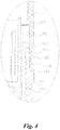
- a cosmetics container as shown in FIG. 1 , includes an end lip 1, a cover 2, a spring 3, and a base 4.
- the base 4 includes an outer tube 401 and an inner tube 402 for accommodating cosmetics 6.
- a gap 403 is formed between the outer tube 401 and the inner tube 402.
- the outer tube 401 and the inner tube 402 are integrally formed.
- the spring 3 is disposed outside the inner tube 402 and is located in the gap 403.
- the cover 2 is sleeved over the inner tube 402. The bottom end of the cover 2 is connected to the top end of the spring 3 and can move up and down along the gap 403.
- the end lid 1 is snapped on the base 4.
- the inner tube 402 is provided with a barrier sheet 404 near the top of the inner tube 402.
- the barrier sheet 404 and the tube wall of the inner tube 402 form an accommodating cavity 405 for accommodating the cosmetics 6.
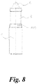
- the cosmetics container of this structure only needs to pull the end lid 1 away from the base 4 when in use, as shown in FIG. 2 , and press the cover 2 downwards by hand, and the cover 2 moves downward relative to the inner tube 402 in the gap 403.
- the cosmetics 6 contained in the inner tube 402 are exposed for use by the user. After use, the hand pressing the cover 2 is released, and the cover 2 can be returned under the action of the spring 3.
- the structure is simple and easy to use.
- the added cover 2 can further protect the cosmetics 6 contained in the inner tube 402.
- the cosmetics 6 are in the form of power strip.
- the outer tube 401 is further provided with a protrusion 408 on the outer wall thereof.
- the inner wall of the end lid 1 near the bottom end is provided with an annular neck 102.
- the protrusion 408 and the annular neck 102 can be snap-fitted with each other.
- the number of protrusions 408 is at least three.
- the outer tube 401 comprises a front end portion 4011 and a main body portion 4012.
- the front end portion 4011 has a smaller outer diameter than the main body portion 4012.
- the protrusion 408 is located on the outer wall of the front end portion 4011.
- a boss 407 is formed between the outer wall of the front end portion 4011 and the outer wall of the main body portion 4012.
- the boss 407 is located below the protrusion 408.
- the bottom end of the end lid 1 can be abutted against the boss 407. Therefore, the arrangement of the boss 407 acts as a limit.
- a first annular inner rim 101 may be opened on the inner wall of the end lid 1 near the bottom end.
- the first annular inner rim 101 is located above the annular neck 102.
- the outer wall of the front end of the cover 2 is provided with a first annular outer rim 201.
- the top end of the first annular outer rim 201 can be abutted against the bottom of the first annular inner rim 101.
- the bottom end of the first annular outer rim 201 can be abutted against the top end of the front end portion 4011.
- the spring 3 is in a compressed state.
- a second annular outer rim 202 may be provided on the outer wall of the cover 2 near the bottom end.
- a second annular inner rim 409 may be provided on the inner wall of the outer tube 401.
- the second annular outer rim 202 and the second annular inner rim 409 can be snap-fitted with each other.
- the end lid 1 and the cover 2 of this structure cooperate.
- the bottom of the first annular inner rim 101 of the inner wall of the end lid 1 is abutted against the top end of the first annular outer rim 201 of the cover 2 to compress the spring 3.
- the entire cover 2 moves downwards relative to the inner tube 402.
- the bottom end of the first annular outer rim 201 is abutted against the front end 4011 of the end lid 1.
- the second annular outer rim 202 and the second annular inner rim 409 are engaged with each other, so that the cover 2 can be further fixed and limited.
- the structure is simple and easy to operate.
- the method of using the cosmetics container of this structure can be briefly described as: the end lid 1 is pulled upwards forcefully, under the spring force of the spring 3, the second annular outer rim 202 is disengaged from the second annular inner rim 409, so that the entire cover 2 moves upward relative to the inner tube 402, and then the cover 2 is pressed downward again, so that the cosmetics 6 in the inner tube 402 can be used by being exposed.
- a bottom lid 5 may also be included.
- a countersink opening 406 is provided at the bottom of the base 4.
- the bottom lid 5 is embedded in the opening 406.
- the cover 2 is of a transparent material structure.
- the cover 2 of this transparent material structure allows the user to observe the concealed cosmetics 6 without removing it, and is easy to use.
- both the end lid 1 and the base 4 have a dark-colored material structure.
- the end lid 1 and the base 4 of the dark-colored material structure can further protect the cosmetics 6 and prevent their deterioration due to light irradiation.
Landscapes
- Closures For Containers (AREA)
Applications Claiming Priority (1)
| Application Number | Priority Date | Filing Date | Title |
|---|---|---|---|
| PCT/CN2015/094024 WO2017075815A1 (zh) | 2015-11-06 | 2015-11-06 | 化妆品容器 |
Publications (2)
| Publication Number | Publication Date |
|---|---|
| EP3372111A1 true EP3372111A1 (de) | 2018-09-12 |
| EP3372111A4 EP3372111A4 (de) | 2019-08-21 |
Family
ID=58661452
Family Applications (1)
| Application Number | Title | Priority Date | Filing Date |
|---|---|---|---|
| EP15907657.9A Withdrawn EP3372111A4 (de) | 2015-11-06 | 2015-11-06 | Kosmetikbehälter |
Country Status (4)
| Country | Link |
|---|---|
| US (1) | US20180344010A1 (de) |
| EP (1) | EP3372111A4 (de) |
| CN (1) | CN206576501U (de) |
| WO (1) | WO2017075815A1 (de) |
Families Citing this family (2)
| Publication number | Priority date | Publication date | Assignee | Title |
|---|---|---|---|---|
| CN111248603B (zh) * | 2020-04-02 | 2024-09-10 | 浙江晟祺实业有限公司 | 一种化妆品容器 |
| CN111470183B (zh) * | 2020-05-08 | 2024-04-26 | 郗大伟 | 一种可装载两种化妆品的瓶子 |
Family Cites Families (19)
| Publication number | Priority date | Publication date | Assignee | Title |
|---|---|---|---|---|
| US715881A (en) * | 1902-03-31 | 1902-12-16 | Thomas H Scott | Fountain shaving-brush. |
| US1801464A (en) * | 1929-02-16 | 1931-04-21 | Ament Lucy Cotton | Holder for lip sticks and the like |
| US2129777A (en) * | 1936-07-16 | 1938-09-13 | Wilber G Pooley | Device for sterilizing barber's duster brush |
| US2417155A (en) * | 1943-12-27 | 1947-03-11 | Shellmar Products Corp | Lipstick holder |
| US2404815A (en) * | 1944-06-13 | 1946-07-30 | Samuel Sontag | Sanitary applicator |
| US2559906A (en) * | 1946-09-17 | 1951-07-10 | Charles M Tursky | Cosmetic pencil holder |
| US2887708A (en) * | 1953-08-07 | 1959-05-26 | Haelan Lab Inc | Dispenser for dispensing liquid by brush, swab or rod application |
| US2982397A (en) * | 1958-10-14 | 1961-05-02 | Ejectoret Sa | Lipstick casings |
| US3359992A (en) * | 1964-11-06 | 1967-12-26 | Avon Prod Inc | Cosmetic applicator |
| US4579134A (en) * | 1977-09-08 | 1986-04-01 | The Bridgeport Metal Goods Manufacturing Co. | Lipstick container |
| JPS5537089U (de) * | 1978-09-04 | 1980-03-10 | ||
| JP2527491Y2 (ja) * | 1990-10-22 | 1997-02-26 | 株式会社吉野工業所 | 棒状化粧品繰出し容器 |
| CN1066033C (zh) * | 1994-07-08 | 2001-05-23 | 株式会社希丹 | 一种化妆品容器 |
| US5531318A (en) * | 1995-03-23 | 1996-07-02 | Coleman; Thomas J. | Holder and enclosure for a piece of hard candy |
| ES1039942Y (es) * | 1998-03-20 | 1999-06-16 | Techpack Espana S L | Estuche para lapiz de labios. |
| CN1274555A (zh) * | 1999-05-19 | 2000-11-29 | 雷克赛姆化妆品包装公司 | 具有弹簧偏压的化妆品支架的化妆品容器 |
| CN2399986Y (zh) * | 1999-10-18 | 2000-10-11 | 郭镇辉 | 能弹性缩回唇膏芯的唇膏盒 |
| CN201005236Y (zh) * | 2006-11-28 | 2008-01-16 | 成真化妆用具(天津)有限公司 | 一种挤压式化妆刷 |
| CN201243726Y (zh) * | 2008-09-01 | 2009-05-27 | 陈秋火 | 手压弹簧式口红容器 |
-
2015
- 2015-11-06 EP EP15907657.9A patent/EP3372111A4/de not_active Withdrawn
- 2015-11-06 WO PCT/CN2015/094024 patent/WO2017075815A1/zh not_active Ceased
- 2015-11-06 CN CN201590000915.0U patent/CN206576501U/zh not_active Expired - Fee Related
- 2015-11-06 US US15/773,786 patent/US20180344010A1/en not_active Abandoned
Also Published As
| Publication number | Publication date |
|---|---|
| WO2017075815A1 (zh) | 2017-05-11 |
| CN206576501U (zh) | 2017-10-24 |
| EP3372111A4 (de) | 2019-08-21 |
| US20180344010A1 (en) | 2018-12-06 |
Similar Documents
| Publication | Publication Date | Title |
|---|---|---|
| KR200453126Y1 (ko) | 스포이드형 화장품 용기 | |
| CN110799061B (zh) | 具有侧面按钮的杆型化妆品材料用容器 | |
| KR200474769Y1 (ko) | 회전 출몰식 화장품 용기 | |
| US20150296956A1 (en) | Loose powder compact with compressible platform | |
| CA2900186C (en) | Non-roll stick product containers | |
| KR20120002205U (ko) | 스포이드형 화장품 용기 | |
| US10058160B2 (en) | Airtight container for cosmetics | |
| KR101666012B1 (ko) | 스틱형 화장품 용기 | |
| US20220160101A1 (en) | Packaging device and refill device | |
| KR20160028553A (ko) | 인출식 팔레트를 갖춘 화장품용기 | |
| EP3372111A1 (de) | Kosmetikbehälter | |
| US9125472B2 (en) | Cosmetic powder container | |
| WO2016011631A1 (zh) | 化妆品容器 | |
| CN110074541B (zh) | 化妆品容器 | |
| KR200456797Y1 (ko) | 사용량에 따라 내부접시가 승강되게 한 화장품 용기 | |
| KR102644985B1 (ko) | 슬라이딩 버튼이 구비된 립스틱 용기 | |
| KR101867274B1 (ko) | 화장료의 형상이 유지되는 화장용구 | |
| CN106820538B (zh) | 气垫粉饼容器 | |
| KR20130001774U (ko) | 스포이드형 화장품 용기 | |
| JPS628825Y2 (de) | ||
| KR101265517B1 (ko) | 막대형 내용물을 담는 진공용기 | |
| KR102009375B1 (ko) | 스틱형 화장품 용기 | |
| KR20160037027A (ko) | 진공 배출펌프를 구비한 튜브용기 | |
| KR101885188B1 (ko) | 화장품용 퍼프장치 | |
| KR20140005013U (ko) | 입술용 화장품 용기 |
Legal Events
| Date | Code | Title | Description |
|---|---|---|---|
| PUAI | Public reference made under article 153(3) epc to a published international application that has entered the european phase |
Free format text: ORIGINAL CODE: 0009012 |
|
| 17P | Request for examination filed |
Effective date: 20180605 |
|
| AK | Designated contracting states |
Kind code of ref document: A1 Designated state(s): AL AT BE BG CH CY CZ DE DK EE ES FI FR GB GR HR HU IE IS IT LI LT LU LV MC MK MT NL NO PL PT RO RS SE SI SK SM TR |
|
| AX | Request for extension of the european patent |
Extension state: BA ME |
|
| DAV | Request for validation of the european patent (deleted) | ||
| DAX | Request for extension of the european patent (deleted) | ||
| A4 | Supplementary search report drawn up and despatched |
Effective date: 20190718 |
|
| RIC1 | Information provided on ipc code assigned before grant |
Ipc: A45D 40/10 20060101AFI20190712BHEP |
|
| STAA | Information on the status of an ep patent application or granted ep patent |
Free format text: STATUS: THE APPLICATION IS DEEMED TO BE WITHDRAWN |
|
| 18D | Application deemed to be withdrawn |
Effective date: 20200218 |