EP3372373B1 - Kunststoffgefäss mit beherbergtem metallelement und verfahren seiner herstellung - Google Patents
Kunststoffgefäss mit beherbergtem metallelement und verfahren seiner herstellung Download PDFInfo
- Publication number
- EP3372373B1 EP3372373B1 EP18160365.5A EP18160365A EP3372373B1 EP 3372373 B1 EP3372373 B1 EP 3372373B1 EP 18160365 A EP18160365 A EP 18160365A EP 3372373 B1 EP3372373 B1 EP 3372373B1
- Authority
- EP
- European Patent Office
- Prior art keywords
- vessel
- cover
- metal element
- plastic
- vessel element
- Prior art date
- Legal status (The legal status is an assumption and is not a legal conclusion. Google has not performed a legal analysis and makes no representation as to the accuracy of the status listed.)
- Active
Links
Images


Classifications
-
- A—HUMAN NECESSITIES
- A47—FURNITURE; DOMESTIC ARTICLES OR APPLIANCES; COFFEE MILLS; SPICE MILLS; SUCTION CLEANERS IN GENERAL
- A47G—HOUSEHOLD OR TABLE EQUIPMENT
- A47G19/00—Table service
- A47G19/22—Drinking vessels or saucers used for table service
- A47G19/2205—Drinking glasses or vessels
- A47G19/2261—Drinking glasses or vessels with integral means to prevent the glass from slipping or tipping-over
-
- A—HUMAN NECESSITIES
- A47—FURNITURE; DOMESTIC ARTICLES OR APPLIANCES; COFFEE MILLS; SPICE MILLS; SUCTION CLEANERS IN GENERAL
- A47G—HOUSEHOLD OR TABLE EQUIPMENT
- A47G19/00—Table service
- A47G19/22—Drinking vessels or saucers used for table service
- A47G19/2205—Drinking glasses or vessels
- A47G19/2227—Drinking glasses or vessels with means for amusing or giving information to the user
-
- B—PERFORMING OPERATIONS; TRANSPORTING
- B29—WORKING OF PLASTICS; WORKING OF SUBSTANCES IN A PLASTIC STATE IN GENERAL
- B29C—SHAPING OR JOINING OF PLASTICS; SHAPING OF MATERIAL IN A PLASTIC STATE, NOT OTHERWISE PROVIDED FOR; AFTER-TREATMENT OF THE SHAPED PRODUCTS, e.g. REPAIRING
- B29C45/00—Injection moulding, i.e. forcing the required volume of moulding material through a nozzle into a closed mould; Apparatus therefor
- B29C45/0053—Injection moulding, i.e. forcing the required volume of moulding material through a nozzle into a closed mould; Apparatus therefor combined with a final operation, e.g. shaping
- B29C45/006—Joining parts moulded in separate cavities
-
- B—PERFORMING OPERATIONS; TRANSPORTING
- B29—WORKING OF PLASTICS; WORKING OF SUBSTANCES IN A PLASTIC STATE IN GENERAL
- B29C—SHAPING OR JOINING OF PLASTICS; SHAPING OF MATERIAL IN A PLASTIC STATE, NOT OTHERWISE PROVIDED FOR; AFTER-TREATMENT OF THE SHAPED PRODUCTS, e.g. REPAIRING
- B29C69/00—Combinations of shaping techniques not provided for in a single one of main groups B29C39/00 - B29C67/00, e.g. associations of moulding and joining techniques; Apparatus therefore
-
- B—PERFORMING OPERATIONS; TRANSPORTING
- B65—CONVEYING; PACKING; STORING; HANDLING THIN OR FILAMENTARY MATERIAL
- B65D—CONTAINERS FOR STORAGE OR TRANSPORT OF ARTICLES OR MATERIALS, e.g. BAGS, BARRELS, BOTTLES, BOXES, CANS, CARTONS, CRATES, DRUMS, JARS, TANKS, HOPPERS, FORWARDING CONTAINERS; ACCESSORIES, CLOSURES, OR FITTINGS THEREFOR; PACKAGING ELEMENTS; PACKAGES
- B65D1/00—Rigid or semi-rigid containers having bodies formed in one piece, e.g. by casting metallic material, by moulding plastics, by blowing vitreous material, by throwing ceramic material, by moulding pulped fibrous material or by deep-drawing operations performed on sheet material
- B65D1/22—Boxes or like containers with side walls of substantial depth for enclosing contents
- B65D1/26—Thin-walled containers, e.g. formed by deep-drawing operations
- B65D1/265—Drinking cups
-
- B—PERFORMING OPERATIONS; TRANSPORTING
- B65—CONVEYING; PACKING; STORING; HANDLING THIN OR FILAMENTARY MATERIAL
- B65D—CONTAINERS FOR STORAGE OR TRANSPORT OF ARTICLES OR MATERIALS, e.g. BAGS, BARRELS, BOTTLES, BOXES, CANS, CARTONS, CRATES, DRUMS, JARS, TANKS, HOPPERS, FORWARDING CONTAINERS; ACCESSORIES, CLOSURES, OR FITTINGS THEREFOR; PACKAGING ELEMENTS; PACKAGES
- B65D15/00—Containers having bodies formed by interconnecting or uniting two or more rigid, or substantially rigid, sections made of different materials
- B65D15/02—Containers having bodies formed by interconnecting or uniting two or more rigid, or substantially rigid, sections made of different materials of curved, or partially curved, cross-section, e.g. cans, drums
- B65D15/16—Containers having bodies formed by interconnecting or uniting two or more rigid, or substantially rigid, sections made of different materials of curved, or partially curved, cross-section, e.g. cans, drums with curved, or partially curved, walls made of plastics material
-
- A—HUMAN NECESSITIES
- A47—FURNITURE; DOMESTIC ARTICLES OR APPLIANCES; COFFEE MILLS; SPICE MILLS; SUCTION CLEANERS IN GENERAL
- A47G—HOUSEHOLD OR TABLE EQUIPMENT
- A47G2200/00—Details not otherwise provided for in A47G
- A47G2200/10—Magnetism
- A47G2200/106—Permanent
-
- B—PERFORMING OPERATIONS; TRANSPORTING
- B29—WORKING OF PLASTICS; WORKING OF SUBSTANCES IN A PLASTIC STATE IN GENERAL
- B29C—SHAPING OR JOINING OF PLASTICS; SHAPING OF MATERIAL IN A PLASTIC STATE, NOT OTHERWISE PROVIDED FOR; AFTER-TREATMENT OF THE SHAPED PRODUCTS, e.g. REPAIRING
- B29C45/00—Injection moulding, i.e. forcing the required volume of moulding material through a nozzle into a closed mould; Apparatus therefor
- B29C45/0053—Injection moulding, i.e. forcing the required volume of moulding material through a nozzle into a closed mould; Apparatus therefor combined with a final operation, e.g. shaping
- B29C45/006—Joining parts moulded in separate cavities
- B29C2045/0067—Joining parts moulded in separate cavities interposing an insert between the parts to be assembled
-
- B—PERFORMING OPERATIONS; TRANSPORTING
- B29—WORKING OF PLASTICS; WORKING OF SUBSTANCES IN A PLASTIC STATE IN GENERAL
- B29K—INDEXING SCHEME ASSOCIATED WITH SUBCLASSES B29B, B29C OR B29D, RELATING TO MOULDING MATERIALS OR TO MATERIALS FOR MOULDS, REINFORCEMENTS, FILLERS OR PREFORMED PARTS, e.g. INSERTS
- B29K2067/00—Use of polyesters or derivatives thereof, as moulding material
-
- B—PERFORMING OPERATIONS; TRANSPORTING
- B29—WORKING OF PLASTICS; WORKING OF SUBSTANCES IN A PLASTIC STATE IN GENERAL
- B29K—INDEXING SCHEME ASSOCIATED WITH SUBCLASSES B29B, B29C OR B29D, RELATING TO MOULDING MATERIALS OR TO MATERIALS FOR MOULDS, REINFORCEMENTS, FILLERS OR PREFORMED PARTS, e.g. INSERTS
- B29K2069/00—Use of PC, i.e. polycarbonates or derivatives thereof, as moulding material
-
- B—PERFORMING OPERATIONS; TRANSPORTING
- B29—WORKING OF PLASTICS; WORKING OF SUBSTANCES IN A PLASTIC STATE IN GENERAL
- B29K—INDEXING SCHEME ASSOCIATED WITH SUBCLASSES B29B, B29C OR B29D, RELATING TO MOULDING MATERIALS OR TO MATERIALS FOR MOULDS, REINFORCEMENTS, FILLERS OR PREFORMED PARTS, e.g. INSERTS
- B29K2105/00—Condition, form or state of moulded material or of the material to be shaped
- B29K2105/06—Condition, form or state of moulded material or of the material to be shaped containing reinforcements, fillers or inserts
- B29K2105/20—Inserts
- B29K2105/203—Magnetic parts
-
- B—PERFORMING OPERATIONS; TRANSPORTING
- B29—WORKING OF PLASTICS; WORKING OF SUBSTANCES IN A PLASTIC STATE IN GENERAL
- B29K—INDEXING SCHEME ASSOCIATED WITH SUBCLASSES B29B, B29C OR B29D, RELATING TO MOULDING MATERIALS OR TO MATERIALS FOR MOULDS, REINFORCEMENTS, FILLERS OR PREFORMED PARTS, e.g. INSERTS
- B29K2705/00—Use of metals, their alloys or their compounds, for preformed parts, e.g. for inserts
- B29K2705/08—Transition metals
- B29K2705/12—Iron
-
- B—PERFORMING OPERATIONS; TRANSPORTING
- B29—WORKING OF PLASTICS; WORKING OF SUBSTANCES IN A PLASTIC STATE IN GENERAL
- B29K—INDEXING SCHEME ASSOCIATED WITH SUBCLASSES B29B, B29C OR B29D, RELATING TO MOULDING MATERIALS OR TO MATERIALS FOR MOULDS, REINFORCEMENTS, FILLERS OR PREFORMED PARTS, e.g. INSERTS
- B29K2995/00—Properties of moulding materials, reinforcements, fillers, preformed parts or moulds
- B29K2995/0003—Properties of moulding materials, reinforcements, fillers, preformed parts or moulds having particular electrical or magnetic properties, e.g. piezoelectric
- B29K2995/0008—Magnetic or paramagnetic
-
- B—PERFORMING OPERATIONS; TRANSPORTING
- B29—WORKING OF PLASTICS; WORKING OF SUBSTANCES IN A PLASTIC STATE IN GENERAL
- B29L—INDEXING SCHEME ASSOCIATED WITH SUBCLASS B29C, RELATING TO PARTICULAR ARTICLES
- B29L2031/00—Other particular articles
- B29L2031/712—Containers; Packaging elements or accessories, Packages
- B29L2031/7132—Bowls, Cups, Glasses
-
- B—PERFORMING OPERATIONS; TRANSPORTING
- B65—CONVEYING; PACKING; STORING; HANDLING THIN OR FILAMENTARY MATERIAL
- B65D—CONTAINERS FOR STORAGE OR TRANSPORT OF ARTICLES OR MATERIALS, e.g. BAGS, BARRELS, BOTTLES, BOXES, CANS, CARTONS, CRATES, DRUMS, JARS, TANKS, HOPPERS, FORWARDING CONTAINERS; ACCESSORIES, CLOSURES, OR FITTINGS THEREFOR; PACKAGING ELEMENTS; PACKAGES
- B65D2313/00—Connecting or fastening means
- B65D2313/04—Connecting or fastening means of magnetic type
-
- H—ELECTRICITY
- H01—ELECTRIC ELEMENTS
- H01F—MAGNETS; INDUCTANCES; TRANSFORMERS; SELECTION OF MATERIALS FOR THEIR MAGNETIC PROPERTIES
- H01F7/00—Magnets
- H01F7/02—Permanent magnets [PM]
Definitions
- the present invention relates to a plastic vessel with a housed metal element and a method of its manufacture.
- the present invention relates in particular to a plastic vessel with a magnetic metal element for use in conjunction with a means of transport and in particular for use in a vehicle of any kind and / or for people with restricted motor skills and / or attention and / or perception and / or as a decorative one Element.
- thermoplastic properties of the plastic come into full effect, the volume of, for example, polycarbonate around 0 , 5 to 0.7% percent shrinks.
- a metal element has comparatively strongly different temperature expansion properties, which is why one which is already in its intended position during the injection molding, in particular near a surface on the bottom of the vessel, is completely surrounded by cooling and solidifying plastic
- Metal element starting from the injection point, causes cracks in the plastic, which become increasingly larger, especially when there is considerable stress from use, for example when a vessel used as a drinking glass, for example, is rinsed several times.
- a metal element embedded in a plastic vessel during injection molding leads to faulty designs of the vessel in the vicinity of the embedded metal element and / or to an undesirably short service life of a macroscopically undamaged vessel.
- Such a vessel with unwanted cracks can therefore not meet current aesthetic requirements, because it can in particular no longer be maintained or cleaned satisfactorily.
- the plastic incompletely surrounding the metal element no longer adequately protects the metal element from external influences, such as those that occur, for example, when cleaning in a dishwasher, which means that the metal element can also be damaged.
- the metal element also comprises a magnet, which is particularly desirable for the use of the vessel as a non-slip vessel in cooperation with a means of transport and in particular for use in a vehicle, the magnetic remanence of the magnet is not only at a temperature in the stated temperature range of Above 300 degrees it is considerably demagnetized but can also be massively impaired in a lower temperature range of, for example, 200 degrees.
- a drinking glass with a container part and a foot part made of plastic designed as an insert is known, the foot part having an insert with a higher specific weight than the plastic for a desirable stability of the drinking glass even when empty or partially filled.
- the insert can be made of metal and designed as a ring or disk.
- a drinking glass made of plastic is known with a base that is desirable for aesthetic and economic reasons and, in particular, with a height that is great compared to its diameter. Compared to the thickness of the edge of the drinking glass, the thickness of the base is at least 10 times.
- the drinking glass is made in two pieces, with a main body which has a recess in its base into which a solid stopper made of plastic is inserted, by means of which the solid base is provided.
- the main body and plug are connected to one another by means of shrinkage of the not yet cooled main body.
- a further object of the present invention is to specify a method for production which is suitable for a plastic vessel according to the invention as mentioned above and which is in particular also suitable for inexpensive industrial mass production.
- the invention particularly advantageously relates to a plastic vessel which houses a metal element in its foot, the plastic vessel being designed in two parts with a vessel element and a cover, and wherein a recess is formed in the foot of the vessel element which is covered by the cover in such a way that a central closed area of the recess is provided which houses the metal element, and wherein the vessel and the cover are thermoplastically bonded together under pressure.
- thermoplastic connection by means of thermoplastic shrinkage of the vessel element during its cooling and hardening and with an already completely solidified cover or with thermoplastic shrinkage of the cover during its cooling and hardening and with an already completely solidified vessel element, in each case at a suitable pressure, is advantageous pressed onto the vessel element, and provided at a suitable predetermined temperature, the pressure and in particular the temperature being selected such that no cracks occur in the plastic when the vessel element and cover are connected and that the magnetic properties of a magnetic metal element are not impaired.
- the recess for housing the metal element of a preceding vessel element comprises in particular an outer edge and an inner edge spaced apart from the outer edge, which surrounds the central area of the recess for housing the metal element, so that between the inner and outer edge an area of the Recess is provided that the central area surrounds.
- the cover comprises an arch which rises in relation to a central region of the cover and surrounds the central region of the cover and which is designed to correspond to the recess of the vessel element surrounding the central region of the vessel element in such a way that when the region for accommodating the metal element is covered the arch of the cover is arranged in the area of the recess of the vessel element surrounding the area for accommodating the metal element.
- the above-mentioned sheet of the cover has an outer edge, which is the outer edge of the cover, and which corresponds to the outer edge of the vessel element and is arranged adjacent to this, and an inner edge which is connected to the inner Edge of the vessel element corresponds and is arranged adjacent to this.
- the cover like the above cover, has an advantageous structure with a meander shape in section, the profile of which corresponds to the structure of the base of the vessel element, so that an advantageously large contact area is provided between the vessel element and the cover for their stable and tight connection.
- a circumferential bead is formed on the inside on the outer edge of the vessel element.
- a step corresponding to the bead is formed on the outside of the outer edge of the cover in such a way that the bead is locked with the step, whereby a particularly tight, tight and stable connection of the vessel element and cover is achieved.
- a gradation is formed which corresponds to the inner edge of the vessel element, which surrounds the area for housing the metal element, in such a way that the inner edge is on the inside adjacent to the protruding inner one Edge of the vessel element is arranged and, in addition, the inside step rests on the inner edge of the vessel element, which advantageously ensures that despite the shrinkage of the vessel element in the direction towards inside to the central area for accommodating the metal element, the cover, which has already completely shrunk afterwards, nevertheless remains in contact with the inner edge of the vessel element with the inner edge of its arch, so that a connection between the cover and the vessel element is ensured there as well.
- the vessel element is suitably designed as a cone which tapers towards the base of the vessel and which can also suitably merge into a cylinder in the region of the base.
- the cover is designed in a suitable manner disc-shaped, the vessel element and the cover each having an axial symmetry with an identical axis of symmetry, and the metal element being suitably designed in a correspondingly flat and symmetrical manner.
- the vessel which is particularly suitable as a drinking glass, at least three webs described above are advantageously formed radially and also symmetrically to the axis.
- the vessel is particularly made of a suitable manner Copolyester such as Tritan (TM) from Eastman Chemical Company or polycarbonate, and thus largely scratch-resistant, transparent and correspondingly durable and aesthetic.
- TM Tritan
- the metal element is also advantageously a magnet, so that the vessel, in cooperation with a suitable means of transport and in particular in cooperation with suitable furnishing elements, is advantageous as a non-slip drinking vessel in a vehicle of any kind and / or as a non-slip, safely manageable vessel for people with restricted motor skills and / or Attention and / or perception can be used.
- a magnet that is particularly well suited for this is designed in particular as a flat disk-shaped cylinder with axial polarity, which can particularly advantageously be a neodymium magnet provided with a copper-nickel protective layer.
- the vessel can also accommodate an RFID tag in the central closed area of its recess, the overall aesthetic impression of the vessel not being impaired by this either.
- means of transport for the transport of drinking vessels in the catering trade and / or at social events such as suitably designed serving trolleys, serving trays, etc. are meant each comprising suitable metal elements interacting with a magnet and / or interacting with such.
- land vehicles such as road or rail vehicles of any type as well as other means of transport of any type such as ships, yachts, boats, cable cars, airplanes, etc. are included, each of which includes suitably designed furnishing elements.
- this refers in particular to people whose safe handling of containers with liquids such as drinking glasses in particular can be questionable and for whom a non-slip container is therefore particularly suitable such as children or people in need of care.
- a vessel comprising a magnetic metal element in cooperation with metallic furnishing elements, such as wall and ceiling elements, cupboards, for example , Shelves, lights, etc. meant.
- metallic furnishing elements such as wall and ceiling elements, cupboards, for example , Shelves, lights, etc.
- one or more vessels adhering to the metal frames of ceiling lights can interact with the light sources of the lights in a particularly aesthetic way.
- Polycarbonate or copolyester as the plastic used and neodymium as a powerful magnetic element are also particularly suitable for using the vessel as an aesthetic decorative element, for example on vertical walls or ceilings and in conjunction with light sources.
- a selected weight ratio of the magnetic element can be the vessel element made of the comparatively light plastic, in particular in the range of approximately plastic / magnet 5: 1 with a corresponding volume ratio, can be particularly advantageous.
- the present invention also relates in particular to a method for producing a plastic vessel according to the invention described above, in which the cover is produced by injection molding in a first step, and in which the cover is stored in a second step until its shrinkage is complete, and in which in a third step the vessel element is manufactured by injection molding, and in which in a fourth step the vessel element is cooled to a predetermined working temperature at which the vessel element still has a predetermined ductility, and in which the shrinkage of the vessel element during cooling still occurs is not completely completed, and in which in a fifth step, approximately at the predetermined working temperature of the vessel element, the vessel element is equipped with the metal element, the metal element being arranged in the central region of the vessel element; and in which, in a sixth step, the post-shrinkable cover is also pressed at about the predetermined working temperature by exerting pressure on the cover during simultaneous thermoplastic shrinkage of the vessel element with the vessel element, so that the vessel element enters into a permanent connection with the cover and the complete plastic vessel with the metal element housed
- the above embodiment of the method according to the invention is particularly advantageous since it allows a metal element to be housed completely in a plastic vessel and in particular in the base of a plastic vessel, even together with an RFID tag, without cracks occurring in the plastic.
- the above embodiment of the method according to the invention is also particularly advantageous since it allows inexpensive mass production of vessels according to the invention.
- a pre-produced cover also makes it possible to provide the cover with a predetermined color tone in a simple and cost-effective manner.
- the above embodiment is also particularly advantageous, since it also allows a magnetic element to be housed completely in the foot of a plastic vessel without significantly impairing the intended use of the vessel with the magnetic element in cooperation with a suitable means of transport and in particular as a non-slip drinking vessel in a vehicle.
- an above working temperature of about 120 degrees in the interior of the plastic is particularly suitable, since at this temperature the magnetic properties of the magnetic element are largely retained, especially when using a neodymium magnet, and since, in addition, the ductility and further shrinkage of plastic in this temperature range, in particular in conjunction with a suitable application of pressure during further cooling and solidification, create an indissoluble connection of the vessel element with the cover without unwanted cracking in the plastic and thus a sealing of the metal element, which can be a magnet.
- the metal element is not surrounded with its entire surface by the predetermined working temperature and is therefore hardly heated when the vessel element and cover are connected, there is no disruptive influence on the hardening of the plastic due to the temperature behavior of the metal element, whereby a magnetic Metal element is only minimally affected in its magnetization.
- the above embodiment is also particularly advantageous after the vessel element and the cover are injected independently of one another in different steps, whereby a separate coloring in particular of the cover is possible in a simple manner, which in particular enables inexpensive aesthetic individualization of individual vessels but also different vessel series enables. In addition, this promotes the use of the vessel as a decorative element according to the invention.
- the magnetic but also a non-magnetic metal element which when using a transparent plastic such as, for example, advantageously copolyester or polycarbonate, can also be visible from the outside through the bottom or the base of the vessel and also with decorative elements or individualizations such as names, logos , Data, etc. and contribute independently to an individual aesthetic overall impression of the vessel.
- a transparent plastic such as, for example, advantageously copolyester or polycarbonate
- the cover can suitably be made smaller than the vessel element and its relative dimensions with respect to the dimensions of the vessel element can be designed in such a way that, in particular when the vessel element and cover are axially symmetrical, the shrinkage of the vessel element also acts radially on the cover and thus contributes to a permanent connection between the vessel element and the cover.
- an aesthetically desirable overall impression of the plastic vessel is also promoted in this way.
- the vessel element can also be pre-produced and pressed as a completely receding vessel element with a cover that has not yet fully hardened / cooled, which is, however, comparatively more complex and less reliable, which is why the embodiment according to the invention described above with the pre-produced cover is advantageous and is therefore preferred.
- the seam between the vessel element and cover can additionally be provided with a welding mirror, whereby the sealing of the housed metal element is further strengthened.
- the vessel element at least when it is equipped with the metal element comprising a magnet, is arranged on a magnetic mandrel with its foot facing upwards, so that when the vessel element is equipped with the metal element in a simple and inexpensive manner, a predetermined one is particularly advantageous Polarity of an axially polarized magnet is specified, which also eliminates the need for extensive care when stocking and positioning when equipping the metal elements and is accordingly inexpensive.
- the RFID tag When accommodating a suitable essentially two-dimensional RFID tag together with the metal element, the RFID tag can first be connected to the metal element and then the receptacle can be equipped with the RFID tag and the metal element.
- the RFID tag can be glued to the metal element for this purpose, or a metallic antenna element of the RFID tag can also adhere to a magnetic metal element due to its magnetic properties.
- a plastic vessel according to the invention as described above houses a metal element comprising a magnetic element and is used in particular as a drinking vessel in cooperation with a suitable means of transport and in particular in a vehicle of any kind.
- a plastic vessel according to the invention which houses a metal element and which houses in particular a metal element comprising a magnet is, as described above, according to the invention in particular as a drinking vessel in Used together with a suitable means of transport and in particular in a vehicle of any kind and / or as a decorative element and / or for handling people with restricted motor skills and / or perception and / or attention and / or as a decorative element.
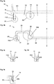
- FIG. 1a shows a schematic perspective illustration of a vessel G according to an embodiment of the invention obliquely from above with the vessel element 1, on the foot 10 of which the cover 2 is arranged, a space for accommodating the metal element 3 being provided
- Figure 1b shows a corresponding perspective illustration of the vessel G from FIG Fig. 1a from diagonally below
- Figure 1c shows a schematic plan view of the vessel G from FIG Figures 1a and b and 1d a side view of the vessel G of Figures 1a, b and c ,
- the cover 2 and the metal element 3 wherein in particular in the illustration of Fig. 1d
- details of the cover 2 have been omitted.
- the VV line from Figures 1c and d each characterizes a longitudinal section through the center of the vessel G, which in the execution of Fig. 1 exemplary and advantageously axially symmetrical with the line VV of Fig. 1d is designed as an axis of symmetry and as a cone tapering towards the foot 10 of the vessel element 1, which is advantageous for a vessel G that can be easily stacked one inside the other and that can in particular be a drinking vessel.
- FIG. 8 shows an enlarged perspective illustration of the metal element 3 from FIG Fig. 1a to d , which is suitably designed flat, cylindrical, disk-shaped, its flat cylinder corresponding approximately to a central recess between the vessel element 1 and cover 2, which is referred to below Fig. 2 will be described in detail.
- FIG. 1f FIG. 3 shows a section through the metal element 3 from FIG Fig. 1e along the line VV of Fig. 1e , wherein the metal element 3 is, by way of example and advantageously, a magnetic element 30 which is covered by a protective layer 31.
- the vessel element 1 and the cover 2 of the plastic vessel G of Fig. 1 are particularly advantageous for the use of the vessel as a drinking glass and in particular for use as a non-slip vessel in a vehicle made of copolyester or polycarbonate, and thus transparent with a long service life, which is why the vessel G is particularly suitable for people with limited perception and / or attention and / or motor skills.
- the metal element 3 can particularly advantageously be a neodymium Magnet 30 be with a copper-nickel protective layer. Copolyester or polycarbonate as plastic and neodymium as a powerful permanent magnet are also particularly suitable for using the vessel as a decorative element, for example on vertical walls, for example a refrigerator and / or in the vicinity and in conjunction with light sources.
- a weight ratio of plastic to magnetic element of about 5: 1 and a volume ratio of plastic / metal corresponding to the weight ratio can also be particularly suitable, which allows the vessel to be reversed with its foot upwards and its opening downwards, for example in gastronomy to hang / store so that the inside of the vessel is largely protected from dust and dirt.
- Fig. 2a shows the enlarged section A of Fig. 1d a section through the vessel G of Fig. 1 along the line VV of Fig. 1d with the bottom 101 of the vessel element 1 and the foot 10 of the vessel element 1 with its cover 2 and with its embedded metal element 3.
- FIG. 10 shows the foot 10 of the vessel element 1 from FIG Figures 2a
- FIG. 3 shows the metal element 3 of FIG Fig. 2a
- Fig. 2d the cover 2 of the vessel element 1 of Fig. 2a
- the Figures 2b, c and d the foot 10 of the vessel element 1 with the housed metal element 3 and with the cover 2 viewed together as an exploded view of Fig. 2a represent, and in addition the arrows S13 and S12 the direction of their composition to the complete foot 10 of the vessel element 1 of Fig.
- the vessel element 1 of Figures 2a and b comprises a lower outer edge 11 which encloses a lower recess 12 formed in its foot 10.
- the above vessel element 1 also comprises an inner edge 13 which is spaced from the outer edge 11 and surrounds a central area 14 for housing the metal element 3, an area 15 of the recess 12 being provided between the inner edge 13 and the outer edge 11, surrounding the central area 14.
- the cover 2 of Figures 2a and 2d comprises an arch 25 which rises in relation to its central area 24 and surrounds the central area 24, the arch 25 being designed to correspond to the recess 15 such that when the area 14 is covered with the cover 2, the arch 25 is arranged in the recess 15 and wherein the sheet 25 of the cover 2 has an outer edge 21 which is the outer edge 21 of the cover 2, and which corresponds to the outer edge 11 of the vessel element 1 and is arranged adjacent to it.
- the arch 25 of the cover 2 also has an inner edge 23 which corresponds to the inner edge 13 of the vessel element 1 and is arranged adjacent to it.
- the cover 2 thus has in the sectional view of Figures 2a and d a meander-like structure, the profile of which corresponds to the profile of the foot 10 of the vessel element 1.
- the meander-like structure thus enables through its surface, which in Contact is brought into contact with the surface of the profile of the foot 10 of the vessel element 1, a particularly stable connection of the cover 2 to the vessel element 1.
- the above structure of the cover 2 and the vessel element 1 is particularly advantageous for the production of a plastic vessel according to the invention according to a preferred embodiment of the invention, in which an already completely shrunk cover 2 with a not completely hardened vessel element 1 at a predetermined temperature inside the plastic of for copolyester and polycarbonate is pressed at about 120 degrees, with the remaining shrinkage of the vessel element 1 in this embodiment of the invention, the vessel element 1 in this embodiment of the invention presses radially from the outside in the direction R onto the cover 2 and in this way promotes a permanent connection.
- the central area 14 for accommodating the metal element 3 corresponds in a suitable manner essentially to the flat, cylindrical metal element 3 of FIG Figures 2a and 2c so that the housed metal element 3 is disposed adjacent to and supported by the bottom of the inner area 14 and the inner edge 13 of the vessel element 1 and to the central area 24 of the cover.
- edge 11 of the vessel element 1 and the adjacent edge 21 of the cover 2 are about a level 110 on which an erected vessel G stands.
- FIG. 11 shows a schematic representation of the vessel element 1 from FIG Figures 2a and b from below, that is to say from the side facing the cover 2 with the recess 12, the central area 14 of the recess 12, the inner edge 13, the outer area 15 of the recess 12 and the outer edge 11.
- Figures 3b and c each show the cover 2 of the vessel element 1 of FIG Figures 2a and d from the side facing away from the vessel element 1 or from the side facing the vessel element 1 with the central area 24, the arch 25, the inner edge 23 of the arch 25 and the outer edge 21 of the arch 25, after which the cover 2 with the meander-shaped Structure according to Figures 2a and d is formed substantially disc-shaped.
- FIG. 13 shows an enlarged perspective illustration of section A of the assembled vessel G from FIG Fig. 1d obliquely from below with the foot 10 of the vessel element 1, the outer edge 11 of the vessel element 1 and with the outer edge 21, the annular arch 25 and the central area 24 of the cover 2 and with the housed metal element 3.
- FIG. 11 shows an enlarged illustration of the section A of the foot 10 of the vessel element 1 from FIG. 1 which is axially symmetrical with the axis of symmetry VV Figure 2b according to a further advantageous embodiment of the invention
- Figure 4b FIG. 4 shows a corresponding to the embodiment of the vessel element 1 from FIG Figure 4a enlarged view of section A of the correspondingly modified cover 2 from FIG Fig. 2d .
- the vessel element 1 also axially symmetrical with the axis of symmetry VV from Figure 4a is corresponding to the vessel element 1 of Figures 2a and b also designed as a cone tapering towards its foot 10, which merges into a cylinder in area B of its foot 10.
- a bead 11A is formed on the inside, and the inside ring 13 is opposite the ring 13 of the formation of Fig. 2a and b is decreased by a predetermined amount.
- the vessel element corresponds to 1 of Figure 4a the vessel element 1 of Figures 2a and b , which is why reference is made in this regard to the corresponding description of the figures.
- the cover 2 which is also axially symmetrical with the axis of symmetry VV Figure 4b is according to the execution of Figures 2a and d also disc-shaped with an essentially meander-shaped section through the plane in which the axis of symmetry VV of Fig. 1d lies, trained.
- a step 21A is formed which coincides with the bead 11A of the outer edge 11 of the embodiment of FIG Figure 4a corresponds in such a way that when the cover 2 is arranged on the foot 10 of the vessel element of Figure 4a the step 21A of the edge 21 engages with the bead 11A of the edge 11, which in the Figure 4c is shown, which is a synopsis of the section A1 of the cover 2 of Figure 4b with the section A1 of the vessel element 1 of Figure 4a indicates.
- Figure 4d FIG. 12 also shows a modification of the embodiment of the cover 2 from FIG Figures 4b and c , in which the gradation 21A is designed as a groove.
- the inner edge 23 of the cover 2 is also in contrast to the embodiment of FIG Figures 2a and d a step 23A is formed which corresponds to the inner edge 13 in such a way that when the cover 2 is arranged on the foot 10 of the vessel element of Figure 4a the gradation 23A rests on the edge 13, which is in the Figure 4e is shown, which is a synopsis of the section A2 of cover 2 of Figure 4b with the section A2 of the vessel element 1 of Figure 4a indicates.
- FIG. 11 shows a further advantageous modification of the cover 2 from the side facing the vessel element 1 from FIG Figure 3c
- Figure 5b shows the other side of the cover of Fig. 5a
- Fig. 5c a section through the cover of Figure 5a along the line SS of Figure 5a .
- the cover 2 of the execution of Fig. 5 is like cover 2 of Figures 3b and c is essentially disk-shaped and, in contrast to the cover 2 of FIG Figures 3b and c also axially symmetrical to the axis of symmetry VV of Fig. 1d and 5c arranged radial webs 26, which the Connect the outer edge 21 of the arch 25 with its inner edge 23 and the cover 2 in particular against forces acting radially from the outside on the edge of the cover 2 in the event of a thermoplastic shrinkage of an incompletely hardened vessel element 1 and / or caused by an external pressure medium to provide a Stabilize predetermined pressure when connecting the cover 2 to a vessel element 1.
- three trigonal webs 26 are advantageously formed.
- the webs 26 also facilitate an exact positioning of the cover 2 by means of a fitting tool at its predetermined position on the vessel element 1 during manufacture. Otherwise the cover corresponds to 2 of Fig. 5 of cover 2 of Fig. 2 , 3 and 4th , which is why reference is made in this regard to the corresponding description of the figures.
- Figures 6a and 6b show a schematic representation of an advantageous step of an embodiment of the method according to the invention for producing the present invention when equipping the vessel element 1 with a metal element 3 comprising a magnet with axial polarity Can be permanent magnet.
- the magnetic mandrel 4 is polarized in such a way that a predetermined orientation of its polarity is specified for the metal element 3 when it is equipped at its predetermined position on the foot 10 of the vessel element 1.
- Figure 6a shows the equipping of the metal element 3 by means of an equipping tool, not shown for the sake of clarity, in which the polarity of the metal element 3 is oriented such that the metal element 3 is attracted by the magnetic mandrel 4.
- FIG. 12 shows the equipping of the metal element 3, in which the polarity of the metal element 3 is reversed to the polarity of the metal element 3 from FIG Figure 6a is oriented during assembly in such a way that a torque M is exerted on the metal element 3 by the magnetic mandrel 4, as a result of which the metal element 3 is rotated into an orientation that corresponds to the orientation of the metal element 3 from Figure 6a corresponds, so that the metal element 3 is also attracted by the mandrel 4 and is arranged in its predetermined position on the foot of the vessel element 1.
- a protruding mandrel 4 according to the invention when equipping the vessel element 1 with a magnetic metal element 3 is particularly advantageous for the simple and inexpensive production of stackable vessels G accommodating magnetic metal elements 3, since the same polarity orientation of the metal element 3 is ensured.
- the second mandrel 4, not shown, with a permanent magnet with reversed polarity, for example, the polarity of the magnetic metal element 3 of a predetermined first series of vessels G can be specified, while a predetermined second series can easily be provided with an oppositely polarized metal element 3 .
- the first and second series can also be differentiated in a suitable manner by the formation of further distinguishing features such as, for example, a different simple coloration according to the invention of the covers 2 prefabricated in each case for a series.
- the production of different series of vessels G with oppositely polarized magnetic metal elements 3 can be particularly desirable for the use according to the invention as a decorative element, since such vessels can easily be used in pairs adhering to one another at their feet.
- two particularly flat, approximately bowl-shaped vessels G can adhere to one another on opposite sides of a shower curtain, for example, or such vessels of different series can be used not only individually but also, for example, as composite vessels G as, for example, elevated drinking vessels or flower vases, each with one The vessel serves as the enlarged base of the vessel assembled in this way, etc.
- a suitable electromagnet can also be used to provide a defined, predetermined orientation of the polarity of the Magnetic element 3 can be provided in only one mandrel 4, the electromagnet being able to be reversed in a simple manner.
- FIG. 4 shows a modification of the vessel 1 from FIG Fig. 1d , in which the vessel 1 together with the metal element 3 also houses an RFID tag 5, the RFID tag 5 being arranged, for example, adjacent below the metal element 3.
- Fig. 7 shows a schematic flow diagram of the essential steps of an embodiment of a preferred method for producing a vessel G according to the invention, the cover 2 being produced by means of injection molding in a first step S1. After it has been manufactured, the cover 2 is stored in a second step S2 until it has finished shrinking. In a third step S3 the vessel element 1 is manufactured by injection molding and in a fourth step S4 it is cooled to a predetermined working temperature at which the vessel element 1 still has a predetermined ductility at which the shrinkage of the vessel element 1 is not yet completely complete.
- a fifth step S5 the vessel element 1 is equipped with the metal element 3 at the predetermined working temperature of the vessel element 1, the metal element 3 being arranged in the central region 14 of the vessel element 1.
- the shrinking cover 2 is pressed together with the vessel element 1 under pressure and cooled at the predetermined working temperature, so that the vessel element 1 is permanently connected to the cover and the complete plastic vessel with the metal element 3 housed in its base 10 is provided.
- the RFID tag 5 can suitably first be connected to the metal element 3 and then the receptacle 1 can be equipped with the RFID tag 5 and the metal element 3 in step S5.
- the RFID tag 5 can be glued to the metal element 3 for this purpose; or a metallic antenna element of the RFID tag adhere to a magnetic metal member 3 due to its magnetic properties.
- FIG. 1 to 7 The present invention has been described above with reference to FIG Figures 1 to 7 described by way of example on the basis of an advantageously axially symmetrical vessel G with a conical vessel element 1 tapering towards its base 10, it being clear, however, that a plastic vessel according to the invention accommodating a metal element 3 also has many other conceivable geometries and shapes, for example with a square or hexagonal shape or oval cross-section of the vessel element 1 and / or the cover 2, etc. can be designed and manufactured.
Landscapes
- Engineering & Computer Science (AREA)
- Mechanical Engineering (AREA)
- Ceramic Engineering (AREA)
- Manufacturing & Machinery (AREA)
- Table Devices Or Equipment (AREA)
- Ceramic Capacitors (AREA)
- Closures For Containers (AREA)
- Details Of Rigid Or Semi-Rigid Containers (AREA)
Priority Applications (1)
| Application Number | Priority Date | Filing Date | Title |
|---|---|---|---|
| HRP20211581TT HRP20211581T1 (hr) | 2017-03-10 | 2018-03-06 | Plastična posuda s integriranim metalnim elementom i postupak njezine proizvodnje |
Applications Claiming Priority (1)
| Application Number | Priority Date | Filing Date | Title |
|---|---|---|---|
| DE102017002306.9A DE102017002306A1 (de) | 2017-03-10 | 2017-03-10 | Kunststoffgefäß mit beherbergtem Metallelement und Verfahren seiner Herstellung |
Publications (2)
| Publication Number | Publication Date |
|---|---|
| EP3372373A1 EP3372373A1 (de) | 2018-09-12 |
| EP3372373B1 true EP3372373B1 (de) | 2021-08-11 |
Family
ID=61581071
Family Applications (1)
| Application Number | Title | Priority Date | Filing Date |
|---|---|---|---|
| EP18160365.5A Active EP3372373B1 (de) | 2017-03-10 | 2018-03-06 | Kunststoffgefäss mit beherbergtem metallelement und verfahren seiner herstellung |
Country Status (6)
| Country | Link |
|---|---|
| US (1) | US10993560B2 (da) |
| EP (1) | EP3372373B1 (da) |
| DE (1) | DE102017002306A1 (da) |
| DK (1) | DK3372373T3 (da) |
| ES (1) | ES2895433T3 (da) |
| HR (1) | HRP20211581T1 (da) |
Families Citing this family (6)
| Publication number | Priority date | Publication date | Assignee | Title |
|---|---|---|---|---|
| US20180044081A1 (en) * | 2016-08-10 | 2018-02-15 | Mary Middelton O'Brien | Collectibles With Bundling Strips And Methods of Manufacture Thereof |
| US10703297B1 (en) * | 2016-08-26 | 2020-07-07 | Apple Inc. | System for holding devices in a passenger vehicle |
| DE202017107536U1 (de) * | 2017-12-11 | 2018-01-15 | Bystronic Laser Ag | Befestigungsvorrichtung für Werkzeugmaschinen und Werkzeugmaschine mit einer Befestigungsvorrichtung |
| US11312611B2 (en) * | 2019-05-13 | 2022-04-26 | Lg Electronics Inc. | Hydrogen water generator |
| GB2614878A (en) * | 2022-01-13 | 2023-07-26 | Langham Product Invent Ltd | A reusable cup |
| WO2025123087A1 (en) * | 2023-12-12 | 2025-06-19 | Actglassy Pty Ltd | Beverage container |
Family Cites Families (19)
| Publication number | Priority date | Publication date | Assignee | Title |
|---|---|---|---|---|
| US2219576A (en) * | 1938-02-16 | 1940-10-29 | Owens Illinois Glass Co | Method of molding hollow shapes |
| US2217514A (en) * | 1938-03-01 | 1940-10-08 | Dorsey Spencer H | Dish |
| GB1083176A (en) * | 1965-08-13 | 1967-09-13 | Wells & Company Ltd A | Improvements in drinking vessels |
| DE2356912A1 (de) * | 1975-07-23 | 1975-05-15 | Marvin Stanley Korshak | Sich selbsttaetig aufrichtende tasse |
| US4308955A (en) * | 1980-05-27 | 1982-01-05 | Liqui-Box Corporation | Interfitting, stackable bottles |
| US4466552A (en) * | 1983-08-08 | 1984-08-21 | American Hospital Supply Corporation | Sterilization container formed of nonwoven material |
| DE8334017U1 (de) * | 1983-11-26 | 1984-02-16 | Michelin Besteck- U. Metallwarenfabrikation Werner Michels, 4150 Krefeld | Trinkglas |
| US5314625A (en) * | 1992-12-29 | 1994-05-24 | Michael Farnelli | External oil pan magnet |
| FR2820963B1 (fr) * | 2001-02-21 | 2004-01-09 | Saint Romain Et Cie Ets | Verre a fond epais en matiere plastique |
| US20040136177A1 (en) * | 2003-01-13 | 2004-07-15 | Lewis Edward D. | Ultraviolet illuminated fluorescent drinking vessel |
| US20050087255A1 (en) * | 2003-10-23 | 2005-04-28 | Humphrey Richard L. | RF device in drinkware to record data/initiate sequence of behavior |
| KR20050099937A (ko) * | 2005-04-11 | 2005-10-17 | 신석균 | 자화수컵 |
| US7586417B2 (en) * | 2006-11-10 | 2009-09-08 | Rexam Healthcare Packaging Inc. | RFID insert with disable feature and container that includes such an insert |
| KR101413728B1 (ko) * | 2012-11-08 | 2014-07-01 | 문성수 | 물통팩의 생수주입을 위한 밸브 및 그 밸브가 구비된 디스펜서 |
| US9055831B2 (en) * | 2013-05-12 | 2015-06-16 | Chin Chuan Chen | Bowl having arrangement for adjustably fastening a magnet |
| DE202015000449U1 (de) * | 2014-01-20 | 2015-02-05 | Werbemittelagentur Hagemann Gmbh | Gefäß für Nahrungsmittel |
| US9493271B2 (en) * | 2014-03-04 | 2016-11-15 | The Mentality, LLC | Scoop retention device |
| DE202014002819U1 (de) * | 2014-04-01 | 2014-05-13 | Silke Wagner | Magnet- und Metallelement für Gefäße und Einrichtungselemente zum rutschfesten Aufstellen von Gefäßen in einem Fahrzeug |
| CA2980577A1 (en) * | 2015-03-31 | 2016-10-06 | Leonard Pinchuk | Magnetic base beverage container |
-
2017
- 2017-03-10 DE DE102017002306.9A patent/DE102017002306A1/de active Pending
-
2018
- 2018-03-06 DK DK18160365.5T patent/DK3372373T3/da active
- 2018-03-06 HR HRP20211581TT patent/HRP20211581T1/hr unknown
- 2018-03-06 EP EP18160365.5A patent/EP3372373B1/de active Active
- 2018-03-06 ES ES18160365T patent/ES2895433T3/es active Active
- 2018-03-09 US US15/916,410 patent/US10993560B2/en active Active
Non-Patent Citations (1)
| Title |
|---|
| None * |
Also Published As
| Publication number | Publication date |
|---|---|
| US20180255948A1 (en) | 2018-09-13 |
| EP3372373A1 (de) | 2018-09-12 |
| ES2895433T3 (es) | 2022-02-21 |
| DE102017002306A1 (de) | 2018-09-13 |
| HRP20211581T1 (hr) | 2021-12-24 |
| US10993560B2 (en) | 2021-05-04 |
| DK3372373T3 (da) | 2021-10-18 |
Similar Documents
| Publication | Publication Date | Title |
|---|---|---|
| EP3372373B1 (de) | Kunststoffgefäss mit beherbergtem metallelement und verfahren seiner herstellung | |
| EP3372563B1 (de) | Glasgefäss mit beherbergtem metallelement und verfahren seiner herstellung | |
| EP2675719B1 (de) | Wiederverschliessbare trinkdose | |
| EP2889224B1 (de) | Portionenkapsel zum Zubereiten eines Brüherzeugnisses und Verfahren zu deren Herstellung | |
| DE69021739T2 (de) | Behälterverschluss und verfahren zu seiner herstellung. | |
| EP1882636B1 (de) | Behälter aus Kunststoff sowie Verfahren zum Herstellen eines solchen Behälters | |
| EP0557487A1 (de) | Verschlusseinheit an gebinde für fliessfähiges gut. | |
| DE3307519A1 (de) | Filtervorrichtung mit magnetischem filterhalter | |
| CH561528A5 (en) | Plastic drinking cup - double-wall assembly held by top rims and at bottom centres | |
| DE9406432U1 (de) | Präsentationslade | |
| DE102008006696A1 (de) | Thermo-Behälter mit thermischer Isolierung von Waren für Transport und Lagerung | |
| EP2223867A1 (de) | Dosenförmiger Verpackungsbehälter | |
| DE29613754U1 (de) | Klapphülle | |
| DE112019002302T5 (de) | Herstellungsverfahren für eine quarzviole | |
| DE60220279T2 (de) | Verpackung und verfahren zur herstellung dieses | |
| DE3902570A1 (de) | Zusammengesetzter behaelter | |
| EP2731883B1 (de) | Kennzeichnungsvorrichtung zum markieren eines gefässes für trinkflüssigkeiten | |
| DE3786197T2 (de) | Verfahren zur Herstellung von rohrförmigen Kunststoffbehältern. | |
| DE29915265U1 (de) | Aufsatz für Getränkedosen | |
| DE20021315U1 (de) | Handgriff mit innerem gedrucktem Bild | |
| AT7912U1 (de) | Mehrweg-trinkbecher | |
| EP3655339B1 (de) | Behälter mit mehreren kammern | |
| DE202022106157U1 (de) | Becher-in-Becher-Trinkgefäß | |
| DE3839417A1 (de) | Serviergefaess in form einer kanne | |
| DE102004063109A1 (de) | Verfahren und Mittel zum Verbinden und/oder Abdichten von Teilen |
Legal Events
| Date | Code | Title | Description |
|---|---|---|---|
| PUAI | Public reference made under article 153(3) epc to a published international application that has entered the european phase |
Free format text: ORIGINAL CODE: 0009012 |
|
| STAA | Information on the status of an ep patent application or granted ep patent |
Free format text: STATUS: THE APPLICATION HAS BEEN PUBLISHED |
|
| AK | Designated contracting states |
Kind code of ref document: A1 Designated state(s): AL AT BE BG CH CY CZ DE DK EE ES FI FR GB GR HR HU IE IS IT LI LT LU LV MC MK MT NL NO PL PT RO RS SE SI SK SM TR |
|
| AX | Request for extension of the european patent |
Extension state: BA ME |
|
| STAA | Information on the status of an ep patent application or granted ep patent |
Free format text: STATUS: REQUEST FOR EXAMINATION WAS MADE |
|
| 17P | Request for examination filed |
Effective date: 20190308 |
|
| RBV | Designated contracting states (corrected) |
Designated state(s): AL AT BE BG CH CY CZ DE DK EE ES FI FR GB GR HR HU IE IS IT LI LT LU LV MC MK MT NL NO PL PT RO RS SE SI SK SM TR |
|
| STAA | Information on the status of an ep patent application or granted ep patent |
Free format text: STATUS: EXAMINATION IS IN PROGRESS |
|
| 17Q | First examination report despatched |
Effective date: 20191014 |
|
| GRAP | Despatch of communication of intention to grant a patent |
Free format text: ORIGINAL CODE: EPIDOSNIGR1 |
|
| STAA | Information on the status of an ep patent application or granted ep patent |
Free format text: STATUS: GRANT OF PATENT IS INTENDED |
|
| INTG | Intention to grant announced |
Effective date: 20210309 |
|
| RAP3 | Party data changed (applicant data changed or rights of an application transferred) |
Owner name: MAGLASSX GMBH |
|
| GRAS | Grant fee paid |
Free format text: ORIGINAL CODE: EPIDOSNIGR3 |
|
| GRAA | (expected) grant |
Free format text: ORIGINAL CODE: 0009210 |
|
| STAA | Information on the status of an ep patent application or granted ep patent |
Free format text: STATUS: THE PATENT HAS BEEN GRANTED |
|
| AK | Designated contracting states |
Kind code of ref document: B1 Designated state(s): AL AT BE BG CH CY CZ DE DK EE ES FI FR GB GR HR HU IE IS IT LI LT LU LV MC MK MT NL NO PL PT RO RS SE SI SK SM TR |
|
| REG | Reference to a national code |
Ref country code: CH Ref legal event code: EP |
|
| REG | Reference to a national code |
Ref country code: DE Ref legal event code: R096 Ref document number: 502018006488 Country of ref document: DE |
|
| REG | Reference to a national code |
Ref country code: IE Ref legal event code: FG4D Free format text: LANGUAGE OF EP DOCUMENT: GERMAN Ref country code: AT Ref legal event code: REF Ref document number: 1418919 Country of ref document: AT Kind code of ref document: T Effective date: 20210915 |
|
| REG | Reference to a national code |
Ref country code: FI Ref legal event code: FGE |
|
| REG | Reference to a national code |
Ref country code: DK Ref legal event code: T3 Effective date: 20211013 |
|
| REG | Reference to a national code |
Ref country code: NO Ref legal event code: T2 Effective date: 20210811 |
|
| REG | Reference to a national code |
Ref country code: NL Ref legal event code: FP |
|
| REG | Reference to a national code |
Ref country code: SE Ref legal event code: TRGR |
|
| REG | Reference to a national code |
Ref country code: LT Ref legal event code: MG9D |
|
| REG | Reference to a national code |
Ref country code: HR Ref legal event code: T1PR Ref document number: P20211581 Country of ref document: HR |
|
| PG25 | Lapsed in a contracting state [announced via postgrant information from national office to epo] |
Ref country code: RS Free format text: LAPSE BECAUSE OF FAILURE TO SUBMIT A TRANSLATION OF THE DESCRIPTION OR TO PAY THE FEE WITHIN THE PRESCRIBED TIME-LIMIT Effective date: 20210811 Ref country code: PT Free format text: LAPSE BECAUSE OF FAILURE TO SUBMIT A TRANSLATION OF THE DESCRIPTION OR TO PAY THE FEE WITHIN THE PRESCRIBED TIME-LIMIT Effective date: 20211213 Ref country code: LT Free format text: LAPSE BECAUSE OF FAILURE TO SUBMIT A TRANSLATION OF THE DESCRIPTION OR TO PAY THE FEE WITHIN THE PRESCRIBED TIME-LIMIT Effective date: 20210811 Ref country code: BG Free format text: LAPSE BECAUSE OF FAILURE TO SUBMIT A TRANSLATION OF THE DESCRIPTION OR TO PAY THE FEE WITHIN THE PRESCRIBED TIME-LIMIT Effective date: 20211111 |
|
| REG | Reference to a national code |
Ref country code: ES Ref legal event code: FG2A Ref document number: 2895433 Country of ref document: ES Kind code of ref document: T3 Effective date: 20220221 |
|
| PG25 | Lapsed in a contracting state [announced via postgrant information from national office to epo] |
Ref country code: PL Free format text: LAPSE BECAUSE OF FAILURE TO SUBMIT A TRANSLATION OF THE DESCRIPTION OR TO PAY THE FEE WITHIN THE PRESCRIBED TIME-LIMIT Effective date: 20210811 Ref country code: LV Free format text: LAPSE BECAUSE OF FAILURE TO SUBMIT A TRANSLATION OF THE DESCRIPTION OR TO PAY THE FEE WITHIN THE PRESCRIBED TIME-LIMIT Effective date: 20210811 Ref country code: GR Free format text: LAPSE BECAUSE OF FAILURE TO SUBMIT A TRANSLATION OF THE DESCRIPTION OR TO PAY THE FEE WITHIN THE PRESCRIBED TIME-LIMIT Effective date: 20211112 |
|
| REG | Reference to a national code |
Ref country code: HR Ref legal event code: ODRP Ref document number: P20211581 Country of ref document: HR Payment date: 20220328 Year of fee payment: 5 |
|
| REG | Reference to a national code |
Ref country code: DE Ref legal event code: R097 Ref document number: 502018006488 Country of ref document: DE |
|
| PG25 | Lapsed in a contracting state [announced via postgrant information from national office to epo] |
Ref country code: SM Free format text: LAPSE BECAUSE OF FAILURE TO SUBMIT A TRANSLATION OF THE DESCRIPTION OR TO PAY THE FEE WITHIN THE PRESCRIBED TIME-LIMIT Effective date: 20210811 Ref country code: SK Free format text: LAPSE BECAUSE OF FAILURE TO SUBMIT A TRANSLATION OF THE DESCRIPTION OR TO PAY THE FEE WITHIN THE PRESCRIBED TIME-LIMIT Effective date: 20210811 Ref country code: RO Free format text: LAPSE BECAUSE OF FAILURE TO SUBMIT A TRANSLATION OF THE DESCRIPTION OR TO PAY THE FEE WITHIN THE PRESCRIBED TIME-LIMIT Effective date: 20210811 Ref country code: EE Free format text: LAPSE BECAUSE OF FAILURE TO SUBMIT A TRANSLATION OF THE DESCRIPTION OR TO PAY THE FEE WITHIN THE PRESCRIBED TIME-LIMIT Effective date: 20210811 Ref country code: CZ Free format text: LAPSE BECAUSE OF FAILURE TO SUBMIT A TRANSLATION OF THE DESCRIPTION OR TO PAY THE FEE WITHIN THE PRESCRIBED TIME-LIMIT Effective date: 20210811 Ref country code: AL Free format text: LAPSE BECAUSE OF FAILURE TO SUBMIT A TRANSLATION OF THE DESCRIPTION OR TO PAY THE FEE WITHIN THE PRESCRIBED TIME-LIMIT Effective date: 20210811 |
|
| PLBE | No opposition filed within time limit |
Free format text: ORIGINAL CODE: 0009261 |
|
| STAA | Information on the status of an ep patent application or granted ep patent |
Free format text: STATUS: NO OPPOSITION FILED WITHIN TIME LIMIT |
|
| 26N | No opposition filed |
Effective date: 20220512 |
|
| PG25 | Lapsed in a contracting state [announced via postgrant information from national office to epo] |
Ref country code: SI Free format text: LAPSE BECAUSE OF FAILURE TO SUBMIT A TRANSLATION OF THE DESCRIPTION OR TO PAY THE FEE WITHIN THE PRESCRIBED TIME-LIMIT Effective date: 20210811 |
|
| PG25 | Lapsed in a contracting state [announced via postgrant information from national office to epo] |
Ref country code: MC Free format text: LAPSE BECAUSE OF FAILURE TO SUBMIT A TRANSLATION OF THE DESCRIPTION OR TO PAY THE FEE WITHIN THE PRESCRIBED TIME-LIMIT Effective date: 20210811 |
|
| PG25 | Lapsed in a contracting state [announced via postgrant information from national office to epo] |
Ref country code: LU Free format text: LAPSE BECAUSE OF NON-PAYMENT OF DUE FEES Effective date: 20220306 Ref country code: IE Free format text: LAPSE BECAUSE OF NON-PAYMENT OF DUE FEES Effective date: 20220306 |
|
| REG | Reference to a national code |
Ref country code: HR Ref legal event code: ODRP Ref document number: P20211581 Country of ref document: HR Payment date: 20230228 Year of fee payment: 6 |
|
| P01 | Opt-out of the competence of the unified patent court (upc) registered |
Effective date: 20230528 |
|
| REG | Reference to a national code |
Ref country code: HR Ref legal event code: ODRP Ref document number: P20211581 Country of ref document: HR Payment date: 20240227 Year of fee payment: 7 |
|
| PG25 | Lapsed in a contracting state [announced via postgrant information from national office to epo] |
Ref country code: HU Free format text: LAPSE BECAUSE OF FAILURE TO SUBMIT A TRANSLATION OF THE DESCRIPTION OR TO PAY THE FEE WITHIN THE PRESCRIBED TIME-LIMIT; INVALID AB INITIO Effective date: 20180306 |
|
| PG25 | Lapsed in a contracting state [announced via postgrant information from national office to epo] |
Ref country code: MK Free format text: LAPSE BECAUSE OF FAILURE TO SUBMIT A TRANSLATION OF THE DESCRIPTION OR TO PAY THE FEE WITHIN THE PRESCRIBED TIME-LIMIT Effective date: 20210811 Ref country code: CY Free format text: LAPSE BECAUSE OF FAILURE TO SUBMIT A TRANSLATION OF THE DESCRIPTION OR TO PAY THE FEE WITHIN THE PRESCRIBED TIME-LIMIT Effective date: 20210811 |
|
| PG25 | Lapsed in a contracting state [announced via postgrant information from national office to epo] |
Ref country code: MT Free format text: LAPSE BECAUSE OF FAILURE TO SUBMIT A TRANSLATION OF THE DESCRIPTION OR TO PAY THE FEE WITHIN THE PRESCRIBED TIME-LIMIT Effective date: 20210811 |
|
| REG | Reference to a national code |
Ref country code: HR Ref legal event code: ODRP Ref document number: P20211581 Country of ref document: HR Payment date: 20250226 Year of fee payment: 8 |
|
| PGFP | Annual fee paid to national office [announced via postgrant information from national office to epo] |
Ref country code: DE Payment date: 20250207 Year of fee payment: 8 |
|
| PGFP | Annual fee paid to national office [announced via postgrant information from national office to epo] |
Ref country code: IT Payment date: 20250205 Year of fee payment: 8 |
|
| PGFP | Annual fee paid to national office [announced via postgrant information from national office to epo] |
Ref country code: ES Payment date: 20250409 Year of fee payment: 8 |
|
| PGFP | Annual fee paid to national office [announced via postgrant information from national office to epo] |
Ref country code: CH Payment date: 20250401 Year of fee payment: 8 |
|
| REG | Reference to a national code |
Ref country code: HR Ref legal event code: ODRP Ref document number: P20211581 Country of ref document: HR Payment date: 20260225 Year of fee payment: 9 |
|
| PGFP | Annual fee paid to national office [announced via postgrant information from national office to epo] |
Ref country code: SE Payment date: 20260324 Year of fee payment: 9 |
|
| PGFP | Annual fee paid to national office [announced via postgrant information from national office to epo] |
Ref country code: GB Payment date: 20260323 Year of fee payment: 9 |
|
| PGFP | Annual fee paid to national office [announced via postgrant information from national office to epo] |
Ref country code: NO Payment date: 20260325 Year of fee payment: 9 Ref country code: DK Payment date: 20260323 Year of fee payment: 9 |
|
| PGFP | Annual fee paid to national office [announced via postgrant information from national office to epo] |
Ref country code: HR Payment date: 20260225 Year of fee payment: 9 Ref country code: AT Payment date: 20260312 Year of fee payment: 9 |
|
| PGFP | Annual fee paid to national office [announced via postgrant information from national office to epo] |
Ref country code: BE Payment date: 20260323 Year of fee payment: 9 Ref country code: FI Payment date: 20260305 Year of fee payment: 9 |
|
| PGFP | Annual fee paid to national office [announced via postgrant information from national office to epo] |
Ref country code: NL Payment date: 20260312 Year of fee payment: 9 |
|
| PGFP | Annual fee paid to national office [announced via postgrant information from national office to epo] |
Ref country code: FR Payment date: 20260325 Year of fee payment: 9 |
|
| PGFP | Annual fee paid to national office [announced via postgrant information from national office to epo] |
Ref country code: TR Payment date: 20260225 Year of fee payment: 9 |