EP3372545A1 - Technologie de surveillance de l'utilisation d'un ascenseur - Google Patents
Technologie de surveillance de l'utilisation d'un ascenseur Download PDFInfo
- Publication number
- EP3372545A1 EP3372545A1 EP18155447.8A EP18155447A EP3372545A1 EP 3372545 A1 EP3372545 A1 EP 3372545A1 EP 18155447 A EP18155447 A EP 18155447A EP 3372545 A1 EP3372545 A1 EP 3372545A1
- Authority
- EP
- European Patent Office
- Prior art keywords
- usage
- elevator device
- parameter
- calculated
- elevator
- Prior art date
- Legal status (The legal status is an assumption and is not a legal conclusion. Google has not performed a legal analysis and makes no representation as to the accuracy of the status listed.)
- Withdrawn
Links
- 238000000034 method Methods 0.000 title claims abstract description 27
- 238000012544 monitoring process Methods 0.000 title claims abstract description 9
- 238000012423 maintenance Methods 0.000 claims abstract description 13
- 238000004590 computer program Methods 0.000 claims 2
- 238000006073 displacement reaction Methods 0.000 claims 1
- 230000005540 biological transmission Effects 0.000 description 8
- 238000004891 communication Methods 0.000 description 5
- 230000033001 locomotion Effects 0.000 description 2
- 238000005259 measurement Methods 0.000 description 2
- 230000003287 optical effect Effects 0.000 description 2
- 230000000750 progressive effect Effects 0.000 description 2
- 230000000007 visual effect Effects 0.000 description 2
- 238000013459 approach Methods 0.000 description 1
- 238000010276 construction Methods 0.000 description 1
- 238000001514 detection method Methods 0.000 description 1
- 238000010586 diagram Methods 0.000 description 1
- 238000005516 engineering process Methods 0.000 description 1
- 230000006870 function Effects 0.000 description 1
- 238000007689 inspection Methods 0.000 description 1
- 238000009434 installation Methods 0.000 description 1
- 230000002250 progressing effect Effects 0.000 description 1
- 238000012360 testing method Methods 0.000 description 1
- 238000012546 transfer Methods 0.000 description 1
Images


Classifications
-
- B—PERFORMING OPERATIONS; TRANSPORTING
- B66—HOISTING; LIFTING; HAULING
- B66B—ELEVATORS; ESCALATORS OR MOVING WALKWAYS
- B66B5/00—Applications of checking, fault-correcting, or safety devices in elevators
- B66B5/0006—Monitoring devices or performance analysers
- B66B5/0018—Devices monitoring the operating condition of the elevator system
- B66B5/0025—Devices monitoring the operating condition of the elevator system for maintenance or repair
-
- B—PERFORMING OPERATIONS; TRANSPORTING
- B66—HOISTING; LIFTING; HAULING
- B66B—ELEVATORS; ESCALATORS OR MOVING WALKWAYS
- B66B5/00—Applications of checking, fault-correcting, or safety devices in elevators
- B66B5/0087—Devices facilitating maintenance, repair or inspection tasks
Definitions
- the present invention relates generally to the elevator art field.
- the invention relates to a technique for monitoring use of an elevator.
- Elevator equipment in particular those intended for the transport of persons, must be checked regularly to ensure the necessary safety.
- the legislator sets a deadline for operational areas within which elevator facilities are to be checked.
- an elevator may be subject to varying degrees of progressive wear.
- the present invention is intended to create a possibility for individually optimizing maintenance intervals for elevator devices. This should increase the safety in the use of elevator equipment.
- An elevator device comprises at least passenger and goods lifts, passenger lifts, stairlifts (or other types of lifts for people with physical disabilities), construction site lifts, access ramps, platform lifts and escalators and moving walks.
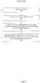
- FIG. 3 is a flowchart showing a method 100 for monitoring use of an elevator apparatus 1000 based on data indicative of use of the elevator apparatus 1000.
- a system 200 according to the invention for implementing the method 100 is described in FIG Fig. 4 shown.
- a use of the elevator device 1000 means a use in which the elevator device 1000 is actually in motion, such as a travel of the elevator device 1000 between two rest positions. Standstills and shutdowns of the elevator device 1000 are not considered to be use.
- first of all data is recorded which indicates a use (movement) of the elevator device 1000.
- the detection takes place with attached to the elevator device sensors 230-232 (see Fig. 4 ). These may measure the duration of use, the distance traveled during use, the load weight during use and / or the consumption of electrical power during use.
- a usage parameter P for the elevator device 1000 is calculated in a subsequent second step 120.
- the usage parameter P is an indicator of the strength of use of the elevator device 1000.
- the strength of the use of the elevator device 1000 means at least the frequency of use (ie how often or how long the elevator device has been moved). In addition to the frequency of elevator use, the load on the elevator device 1000 during use can still be taken into account.
- the frequency of use can be described by the number N of uses, the duration of use t and / or by the distance traveled s of the elevator device 1000.
- the load on the elevator device 1000 during use may be described by the load weight g , for example. Additionally or alternatively, the consumed electrical energy E can be used to describe the strength of the use of the elevator device 1000.
- the calculated usage parameter P merely indicates the frequency of use, ie how often the elevator device 1000 is moved.
- the usage parameter P can be calculated by incrementally summing the acquired usage durations t or traveled distances s of successive uses. As time progresses, therefore, the value of the usage parameter P increases. Alternatively, only the number of uses N can be counted as time progresses.
- the usage parameter P indicates the total usage time T, the total distance traveled S, or simply the total number N of uses with respect to a given starting point. Accordingly, the calculated usage parameter P has the dimension of a time or a path or is dimensionless in the case of counting the uses.
- t i and s i can take different values for each use i , depending on how long the period of use has been or which distance the elevator device 1000 has effectively traveled in use i . It will also be understood that the usage number n i only counts the i th use event and thus is 1 for each use by definition .
- the predetermined starting point for the calculation may be the time of the first operation after a new installation of the elevator device 1000 or just a restart of the elevator device 1000 after a regular maintenance.
- the calculation of the usage parameter P restarts in this case.
- the calculated usage parameter P indicates the frequency of use as well as the load during each use.
- the use of parameter P can be calculated by the i detected for each user usage time t i, the distance traveled s i or the detected Usage number n i (this is for each use by definition 1 as set forth above) weighted with a dimensionless weighting factor F calculated from the detected load weight g .
- the weighting factor F i for the i-th use is calculated from the quotient of the detected loading weight g i for the i-th use and the maximum weight approved by the manufacturer.
- the usage parameter P is recalculated.
- the (weighted) use values ie s i , t i , n i , F i * s i , F i * n i or F i * t i ) determined from the acquired sensor data are added to the previous usage values, as stated above , The value of the usage parameter P thus grows incrementally with each new use.
- the value of the usage parameter P calculated in step S120 is compared with a predetermined usage threshold SP .
- the usage threshold SP indicates the need for maintenance of the elevator device 1000.
- the usage threshold SP is thus a measure of a maximum tolerable use up to a maintenance. It is pre-set by a manufacturer, operator or maintenance worker of the elevator device 1000 so that, when operated properly, no wear-threatening wear on the elevator device 1000 is expected when the usage parameter value P reaches the usage threshold SP .
- the Usage threshold SP can be reset after each maintenance.
- the usage threshold SP can be adapted to the age of the elevator device 1000. It can be reduced in older elevator device 1000.
- the usage threshold SP has the same physical dimension as the calculated usage parameter P. Depending on the usage parameter P used , the usage threshold SP either gives an upper bound on the total weighted distance traveled S, the total usage time T or an upper bound on the (weighted) total number N of uses.
- an output signal is generated which is provided for the acoustic and / or visual representation of the comparison result.
- the generated output signal is provided to an output device (eg smartphone, PC) for audible and / or graphical representation.
- the generation and provision of the output signal can again take place after each use (so to speak in real time), so that an operator, owner and / or user is always informed about the progressive use.
- the comparing step 130 may further include, after each use, a query 132 as to whether the usage parameter meets or exceeds a predetermined warning limit of 80% of the usage threshold SP . If the usage parameter P falls below the 80% warning limit (no branch), thus, the method 100 returns to step 110 to acquire data of subsequent use of the elevator device 1000.
- the usage parameter P after use of the elevator device 1000 reaches or exceeds the predetermined warning limit of 80% (yes branch in FIG Fig. 2 ), a warning signal additional to the output signal is generated and output (step 142).
- the warning signal can in turn be an optical and / or acoustic warning signal for output on an output device (eg smartphone, PC). Warning signal and output signal can be output simultaneously.
- a further query 134 is also provided. In this query, it is checked whether the usage parameter P is greater than or equal to the usage threshold SP . If this is not the case (no decision), the method returns to step 110.
- the usage parameter P reaches or exceeds the usage threshold value SP (yes decision)
- the shutdown or shutdown of the elevator device 1000 is initiated. The switching off 180 of the elevator device 1000 can be supplemented or replaced by the output of a further warning signal.
- Switching off the elevator device 1000 may include automatically maneuvering the elevator device 1000 to a predetermined position.
- the elevator device 1000 is a passenger elevator in a multi-storey building. If the usage parameter P exceeds the usage threshold SP in this case, the elevator for example can drive to the ground floor and open the doors. When all passengers have exited, the passenger elevator can automatically close the doors and switch off until maintenance has taken place.
- the implementation of the shutdown function 180 opens up additional possibilities in terms of increasing safety standards in the use of elevator equipment.
- step 120 of calculating the usage parameter P may be in addition to that described above in connection with FIG Fig. 1 described calculation of an absolute value of the use parameter P additionally one Calculate a usage rate R (step 122) that describes the amount of usage within a given time interval.
- a future date may be selected from the currently determined using parameters P and the above calculated Benutungsrate R then in a subsequent step 124 by comparison with the use of threshold value SP can be estimated at which the usage parameters P is the use of threshold value SP expected to reach or exceed.
- the calculated future time may then be output in visual and / or audible form on an output device (e.g., smartphone, PC).
- an output device e.g., smartphone, PC
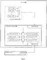
- Fig. 4 shows an inventive system 200 for monitoring a use of an elevator device 1000 in the form of a block diagram.
- the system 200 comprises at least one sensor 230-232 and a computer device 240.
- the computer device 240 comprises a processor, a data memory 220, at least one communication interface 242, an output device 270 and an input device 210.
- the computing device 240 comprises a computation module 244, a generation module 246 and a comparison module 148.
- the three modules 244, 246, 248 are respectively software and / or hardware modules that, for implementation in connection with the FIGS. 1 to 3 described method 100 are provided.
- the three modules 244, 246, 248 are in mutual communication with the processor for this purpose. It is also conceivable that the three modules 244, 246, 248 are formed as submodules of the processor.
- the calculation module 244 is provided for implementing the step 120 of the method 100. It is intended in particular for calculating the usage parameter P. It can also be provided for calculating the usage rate R.
- the comparison module 248 is provided for implementing the step 130 of the method 100. It is provided in particular for carrying out the comparison of the usage parameter P with the usage threshold SP and all parameters or values derived therefrom (such as the comparison parameter Q ).
- the generation module 246 is provided for generating a signal for displaying the comparison results.
- the signal is generated based on the comparison parameter.
- the data memory 220 of the computing device 240 is in communication with the processor. It is designed to buffer captured sensor data. Furthermore, the data memory 220 is also designed to store or buffer the usage values calculated by the processor or modules 244, 246, 248.
- the output device 270 is designed to output the optical and / or acoustic signals generated by the generation module 246. Thus, the usage status of the elevator device 1000 is continuously output to a user via the output device 270.
- the input device 210 is adapted to receive commands or inputs by users and to transmit them to the processor, the modules 244, 248 or the data memory 220.
- a usage threshold value SP can be transmitted to the computing device 240 via the input device 210.
- the input device may include a touch screen, keyboard, and / or mouse.
- the at least one communication interface 242 (in Fig. 4 referred to as interface) is adapted to exchange data between the computing device 240, the sensors 230-232 and / or external electronic devices (such as a user terminal). Such electronic devices may be electronic terminals, such as For example, be smartphones, tablets or PCs.
- the data transmission between the computing device 240 and the external user terminals may be wireless or wired.
- the at least one interface 242 is configured as a wireless interface (for implementing WiFi).
- the transmission between the sensors 230, 231, 232 installed in the elevator device and the computing device 240 can be wireless or wired.
- a variant of the invention provides that the data transmission between the computing device 240 and the external user terminals takes place directly via the Internet.
- the computing device 240 receives an internet server of the data via wireless or wired interfaces from the sensors 230, 231, 232 installed in the elevator device.
- data transmission between the Internet server and Internet-capable external user terminals is provided via appropriate wired or wireless interfaces.
- the data transmission may include the unprocessed sensor data and / or the usage data (such as the calculated comparison parameter, estimated time for reaching the usage threshold value) processed in the computing device 240 (and temporarily stored in the data memory).
- the data transmission can take place continuously, at predetermined time intervals or on request of the user terminal.
- the at least one sensor 230-232 is installed on the elevator device 1000 and serves for the acquisition of measurement data which indicates a use of the elevator device 1000.
- the measurement data may include data on the load weight, the distance traveled, the consumed electrical energy during use of the elevator device 1000.
- the measured data can also provide information about the number of uses.
- the computing device 240 described above may also be installed on the elevator device 1000 or be arranged away from the elevator device 1000.
- the computing device 240 may be a PC, a server computer or even a smartphone, which implements the components or modules described above.
- a variant of the invention provides a real-time representation of the use of the elevator device 1000 on one or more smartphones, tablets or other portable electronic user terminals.
- the output signal generated in the computing device 240 on the basis of the calculated comparison parameter Q is sent directly to the corresponding ones Transfer user terminals. A user can thus check the usage status of an elevator device at any time.
- the technology for monitoring the use of an elevator device described here makes it possible to draw conclusions about a wear of the elevator device.
- thereby maintenance dates for the elevator device can be optimally determined and / or adjusted.
- the safety of elevator equipment is further increased.
Landscapes
- Indicating And Signalling Devices For Elevators (AREA)
- Maintenance And Inspection Apparatuses For Elevators (AREA)
Applications Claiming Priority (1)
| Application Number | Priority Date | Filing Date | Title |
|---|---|---|---|
| DE102017102361.5A DE102017102361A1 (de) | 2017-02-07 | 2017-02-07 | Technik zur Benutzungsüberwachung einer Aufzugseinrichtung |
Publications (1)
| Publication Number | Publication Date |
|---|---|
| EP3372545A1 true EP3372545A1 (fr) | 2018-09-12 |
Family
ID=61187131
Family Applications (1)
| Application Number | Title | Priority Date | Filing Date |
|---|---|---|---|
| EP18155447.8A Withdrawn EP3372545A1 (fr) | 2017-02-07 | 2018-02-07 | Technologie de surveillance de l'utilisation d'un ascenseur |
Country Status (2)
| Country | Link |
|---|---|
| EP (1) | EP3372545A1 (fr) |
| DE (1) | DE102017102361A1 (fr) |
Cited By (1)
| Publication number | Priority date | Publication date | Assignee | Title |
|---|---|---|---|---|
| CN111027934A (zh) * | 2019-12-10 | 2020-04-17 | 深圳市通用互联科技有限责任公司 | 电梯维保任务数据处理方法、装置、计算机设备和存储介质 |
Families Citing this family (1)
| Publication number | Priority date | Publication date | Assignee | Title |
|---|---|---|---|---|
| DE102020205220A1 (de) | 2020-04-24 | 2021-10-28 | Thyssenkrupp Elevator Innovation And Operations Ag | Verfahren und System zur Wartung des Türmechanismus einer Aufzugsanlage |
Citations (4)
| Publication number | Priority date | Publication date | Assignee | Title |
|---|---|---|---|---|
| US4512442A (en) * | 1984-03-30 | 1985-04-23 | Westinghouse Electric Corp. | Method and apparatus for improving the servicing of an elevator system |
| WO2009109471A1 (fr) * | 2008-03-06 | 2009-09-11 | Inventio Ag | Système élévateur et procédé de maintenance d’un tel système élévateur |
| WO2009150251A2 (fr) * | 2008-06-13 | 2009-12-17 | Inventio Ag | Ascenseur et procédé de maintenance d'un ascenseur de ce type |
| DE102011107842A1 (de) * | 2011-07-18 | 2013-01-24 | Rainer Gaus | Fahrstuhlkontrollsystem |
-
2017
- 2017-02-07 DE DE102017102361.5A patent/DE102017102361A1/de not_active Ceased
-
2018
- 2018-02-07 EP EP18155447.8A patent/EP3372545A1/fr not_active Withdrawn
Patent Citations (4)
| Publication number | Priority date | Publication date | Assignee | Title |
|---|---|---|---|---|
| US4512442A (en) * | 1984-03-30 | 1985-04-23 | Westinghouse Electric Corp. | Method and apparatus for improving the servicing of an elevator system |
| WO2009109471A1 (fr) * | 2008-03-06 | 2009-09-11 | Inventio Ag | Système élévateur et procédé de maintenance d’un tel système élévateur |
| WO2009150251A2 (fr) * | 2008-06-13 | 2009-12-17 | Inventio Ag | Ascenseur et procédé de maintenance d'un ascenseur de ce type |
| DE102011107842A1 (de) * | 2011-07-18 | 2013-01-24 | Rainer Gaus | Fahrstuhlkontrollsystem |
Cited By (1)
| Publication number | Priority date | Publication date | Assignee | Title |
|---|---|---|---|---|
| CN111027934A (zh) * | 2019-12-10 | 2020-04-17 | 深圳市通用互联科技有限责任公司 | 电梯维保任务数据处理方法、装置、计算机设备和存储介质 |
Also Published As
| Publication number | Publication date |
|---|---|
| DE102017102361A1 (de) | 2018-08-09 |
Similar Documents
| Publication | Publication Date | Title |
|---|---|---|
| DE102016009032B4 (de) | Maschinenlerneinheit, Spindelersatzbeurteilungsvorrichtung, Steuerung, Werkzeugmaschine, Produktionssystem und maschinelles Lernverfahren, die zur Beurteilung der Notwendigkeit eines Spindelersatzes fähig sind | |
| DE102006045820B4 (de) | Verfahren und Vorrichtung zur automatischen Einstellung eines Motorreglers | |
| DE102018106808B4 (de) | Zustandsbestimmungsvorrichtung | |
| DE102017011754B4 (de) | Maschinenlerneinrichtung zum Lernen eines Montagevorgangs und Komponentenmontagesystem | |
| DE69304258T2 (de) | Verfahren und Einrichtung zur Steuerung von Aufzugstüren | |
| DE102018003266B4 (de) | Controller und maschinelle lernvorrichtung | |
| DE69311221T2 (de) | Verfahren und Vorrichtung für die Kontrolle und das automatische Korrigieren des Verzögerungs-/Stopkommandos eines Personen- oder Lastenaufzuges gemäss Veränderungen in den Betriebsdaten des Systems | |
| DE69928432T2 (de) | Steuerungsgeraet fuer aufzugsgruppe | |
| EP2947035B1 (fr) | Procédé de détermination de la charge d'une machine de travail et machine de travail, en particulier une grue | |
| EP1607192B1 (fr) | Méthode et système pour estimer l'usure des articulations d'un bras de robot | |
| DE112015006635B4 (de) | Aufzugsteuerungsvorrichtung und Verfahren zum Schätzen des Betrags der Ausdehnung/Kontraktion des Drehzahlreglerseils | |
| EP3679433B1 (fr) | Procédé de surveillance d'une machine-outil, notamment pour détecter un outil cassé | |
| DE102018002785B4 (de) | 1 - 8CController und maschinelle Lernvorrichtung | |
| DE102017127098A1 (de) | Gerät und verfahren zum annehmen eines anormalitätsauftretens für teleskopabdeckung | |
| EP3071501B1 (fr) | Procédé destiné au fonctionnement d'un dispositif de commande d'ascenseur | |
| DE102020207792A1 (de) | Training eines künstlichen neuronalen Netzwerkes, künstliches neuronales Netzwerk, Verwendung, Computerprogramm, Speichermedium und Vorrichtung | |
| DE102015226699A1 (de) | Vorrichtung und Verfahren zur Erfassung wenigstens eines Bewegungsparameters einer triebwerksraumlosen Treibscheibenaufzugsanlage | |
| DE102019200407A1 (de) | Teileerkennung und schadencharakterisierung durch deep-learning | |
| EP3372545A1 (fr) | Technologie de surveillance de l'utilisation d'un ascenseur | |
| DE102016002129A1 (de) | Numerische Steuervorrichtung, die eine Überhitzung der Spindel verhindern kann | |
| DE102015001578B4 (de) | Numerische Steuerung für eine Werkzeugmaschine mit einer effizienten regelmäßigen Inspektionsfunktion für Komponenten | |
| DE112012005942B4 (de) | Aufzugsgruppen-Verwaltungsvorrichtung | |
| DE102017219269A1 (de) | Klassifizierung mit automatischer Auswahl aussichtsreicher Lerndaten | |
| DE102017118854A1 (de) | Zellensteuerungssystem | |
| DE102020200051A1 (de) | Verfahren zum Bestimmen von Restnutzungszyklen, Restnutzungszyklusbestimmungsschaltung, Restnutzungszyklusbestimmungsvorrichtung |
Legal Events
| Date | Code | Title | Description |
|---|---|---|---|
| PUAI | Public reference made under article 153(3) epc to a published international application that has entered the european phase |
Free format text: ORIGINAL CODE: 0009012 |
|
| AK | Designated contracting states |
Kind code of ref document: A1 Designated state(s): AL AT BE BG CH CY CZ DE DK EE ES FI FR GB GR HR HU IE IS IT LI LT LU LV MC MK MT NL NO PL PT RO RS SE SI SK SM TR |
|
| AX | Request for extension of the european patent |
Extension state: BA ME |
|
| STAA | Information on the status of an ep patent application or granted ep patent |
Free format text: STATUS: THE APPLICATION IS DEEMED TO BE WITHDRAWN |
|
| 18D | Application deemed to be withdrawn |
Effective date: 20190313 |