EP3372736A1 - Verbindungsaggregat - Google Patents
Verbindungsaggregat Download PDFInfo
- Publication number
- EP3372736A1 EP3372736A1 EP17210440.8A EP17210440A EP3372736A1 EP 3372736 A1 EP3372736 A1 EP 3372736A1 EP 17210440 A EP17210440 A EP 17210440A EP 3372736 A1 EP3372736 A1 EP 3372736A1
- Authority
- EP
- European Patent Office
- Prior art keywords
- connector
- fluid line
- unit according
- connecting unit
- compensation element
- Prior art date
- Legal status (The legal status is an assumption and is not a legal conclusion. Google has not performed a legal analysis and makes no representation as to the accuracy of the status listed.)
- Granted
Links
Images

Classifications
-
- E—FIXED CONSTRUCTIONS
- E03—WATER SUPPLY; SEWERAGE
- E03B—INSTALLATIONS OR METHODS FOR OBTAINING, COLLECTING, OR DISTRIBUTING WATER
- E03B7/00—Water main or service pipe systems
- E03B7/09—Component parts or accessories
- E03B7/10—Devices preventing bursting of pipes by freezing
- E03B7/12—Devices preventing bursting of pipes by freezing by preventing freezing
-
- F—MECHANICAL ENGINEERING; LIGHTING; HEATING; WEAPONS; BLASTING
- F16—ENGINEERING ELEMENTS AND UNITS; GENERAL MEASURES FOR PRODUCING AND MAINTAINING EFFECTIVE FUNCTIONING OF MACHINES OR INSTALLATIONS; THERMAL INSULATION IN GENERAL
- F16L—PIPES; JOINTS OR FITTINGS FOR PIPES; SUPPORTS FOR PIPES, CABLES OR PROTECTIVE TUBING; MEANS FOR THERMAL INSULATION IN GENERAL
- F16L25/00—Construction or details of pipe joints not provided for in, or of interest apart from, groups F16L13/00 - F16L23/00
- F16L25/01—Construction or details of pipe joints not provided for in, or of interest apart from, groups F16L13/00 - F16L23/00 specially adapted for realising electrical conduction between the two pipe ends of the joint or between parts thereof
-
- F—MECHANICAL ENGINEERING; LIGHTING; HEATING; WEAPONS; BLASTING
- F16—ENGINEERING ELEMENTS AND UNITS; GENERAL MEASURES FOR PRODUCING AND MAINTAINING EFFECTIVE FUNCTIONING OF MACHINES OR INSTALLATIONS; THERMAL INSULATION IN GENERAL
- F16L—PIPES; JOINTS OR FITTINGS FOR PIPES; SUPPORTS FOR PIPES, CABLES OR PROTECTIVE TUBING; MEANS FOR THERMAL INSULATION IN GENERAL
- F16L41/00—Branching pipes; Joining pipes to walls
- F16L41/02—Branch units, e.g. made in one piece, welded, riveted
- F16L41/021—T- or cross-pieces
-
- F—MECHANICAL ENGINEERING; LIGHTING; HEATING; WEAPONS; BLASTING
- F16—ENGINEERING ELEMENTS AND UNITS; GENERAL MEASURES FOR PRODUCING AND MAINTAINING EFFECTIVE FUNCTIONING OF MACHINES OR INSTALLATIONS; THERMAL INSULATION IN GENERAL
- F16L—PIPES; JOINTS OR FITTINGS FOR PIPES; SUPPORTS FOR PIPES, CABLES OR PROTECTIVE TUBING; MEANS FOR THERMAL INSULATION IN GENERAL
- F16L41/00—Branching pipes; Joining pipes to walls
- F16L41/02—Branch units, e.g. made in one piece, welded, riveted
- F16L41/023—Y- pieces
-
- F—MECHANICAL ENGINEERING; LIGHTING; HEATING; WEAPONS; BLASTING
- F16—ENGINEERING ELEMENTS AND UNITS; GENERAL MEASURES FOR PRODUCING AND MAINTAINING EFFECTIVE FUNCTIONING OF MACHINES OR INSTALLATIONS; THERMAL INSULATION IN GENERAL
- F16L—PIPES; JOINTS OR FITTINGS FOR PIPES; SUPPORTS FOR PIPES, CABLES OR PROTECTIVE TUBING; MEANS FOR THERMAL INSULATION IN GENERAL
- F16L51/00—Expansion-compensation arrangements for pipe-lines
-
- F—MECHANICAL ENGINEERING; LIGHTING; HEATING; WEAPONS; BLASTING
- F16—ENGINEERING ELEMENTS AND UNITS; GENERAL MEASURES FOR PRODUCING AND MAINTAINING EFFECTIVE FUNCTIONING OF MACHINES OR INSTALLATIONS; THERMAL INSULATION IN GENERAL
- F16L—PIPES; JOINTS OR FITTINGS FOR PIPES; SUPPORTS FOR PIPES, CABLES OR PROTECTIVE TUBING; MEANS FOR THERMAL INSULATION IN GENERAL
- F16L53/00—Heating of pipes or pipe systems; Cooling of pipes or pipe systems
- F16L53/30—Heating of pipes or pipe systems
-
- F—MECHANICAL ENGINEERING; LIGHTING; HEATING; WEAPONS; BLASTING
- F16—ENGINEERING ELEMENTS AND UNITS; GENERAL MEASURES FOR PRODUCING AND MAINTAINING EFFECTIVE FUNCTIONING OF MACHINES OR INSTALLATIONS; THERMAL INSULATION IN GENERAL
- F16L—PIPES; JOINTS OR FITTINGS FOR PIPES; SUPPORTS FOR PIPES, CABLES OR PROTECTIVE TUBING; MEANS FOR THERMAL INSULATION IN GENERAL
- F16L53/00—Heating of pipes or pipe systems; Cooling of pipes or pipe systems
- F16L53/30—Heating of pipes or pipe systems
- F16L53/35—Ohmic-resistance heating
- F16L53/38—Ohmic-resistance heating using elongate electric heating elements, e.g. wires or ribbons
-
- F—MECHANICAL ENGINEERING; LIGHTING; HEATING; WEAPONS; BLASTING
- F16—ENGINEERING ELEMENTS AND UNITS; GENERAL MEASURES FOR PRODUCING AND MAINTAINING EFFECTIVE FUNCTIONING OF MACHINES OR INSTALLATIONS; THERMAL INSULATION IN GENERAL
- F16L—PIPES; JOINTS OR FITTINGS FOR PIPES; SUPPORTS FOR PIPES, CABLES OR PROTECTIVE TUBING; MEANS FOR THERMAL INSULATION IN GENERAL
- F16L57/00—Protection of pipes or objects of similar shape against external or internal damage or wear
- F16L57/02—Protection of pipes or objects of similar shape against external or internal damage or wear against cracking or buckling
-
- F—MECHANICAL ENGINEERING; LIGHTING; HEATING; WEAPONS; BLASTING
- F01—MACHINES OR ENGINES IN GENERAL; ENGINE PLANTS IN GENERAL; STEAM ENGINES
- F01N—GAS-FLOW SILENCERS OR EXHAUST APPARATUS FOR MACHINES OR ENGINES IN GENERAL; GAS-FLOW SILENCERS OR EXHAUST APPARATUS FOR INTERNAL-COMBUSTION ENGINES
- F01N2610/00—Adding substances to exhaust gases
- F01N2610/02—Adding substances to exhaust gases the substance being ammonia or urea
-
- F—MECHANICAL ENGINEERING; LIGHTING; HEATING; WEAPONS; BLASTING
- F01—MACHINES OR ENGINES IN GENERAL; ENGINE PLANTS IN GENERAL; STEAM ENGINES
- F01N—GAS-FLOW SILENCERS OR EXHAUST APPARATUS FOR MACHINES OR ENGINES IN GENERAL; GAS-FLOW SILENCERS OR EXHAUST APPARATUS FOR INTERNAL-COMBUSTION ENGINES
- F01N2610/00—Adding substances to exhaust gases
- F01N2610/10—Adding substances to exhaust gases the substance being heated, e.g. by heating tank or supply line of the added substance
-
- F—MECHANICAL ENGINEERING; LIGHTING; HEATING; WEAPONS; BLASTING
- F01—MACHINES OR ENGINES IN GENERAL; ENGINE PLANTS IN GENERAL; STEAM ENGINES
- F01N—GAS-FLOW SILENCERS OR EXHAUST APPARATUS FOR MACHINES OR ENGINES IN GENERAL; GAS-FLOW SILENCERS OR EXHAUST APPARATUS FOR INTERNAL-COMBUSTION ENGINES
- F01N2610/00—Adding substances to exhaust gases
- F01N2610/14—Arrangements for the supply of substances, e.g. conduits
-
- F—MECHANICAL ENGINEERING; LIGHTING; HEATING; WEAPONS; BLASTING
- F01—MACHINES OR ENGINES IN GENERAL; ENGINE PLANTS IN GENERAL; STEAM ENGINES
- F01N—GAS-FLOW SILENCERS OR EXHAUST APPARATUS FOR MACHINES OR ENGINES IN GENERAL; GAS-FLOW SILENCERS OR EXHAUST APPARATUS FOR INTERNAL-COMBUSTION ENGINES
- F01N2610/00—Adding substances to exhaust gases
- F01N2610/14—Arrangements for the supply of substances, e.g. conduits
- F01N2610/1446—Means for damping of pressure fluctuations in the delivery system, e.g. by puffer volumes or throttling
-
- F—MECHANICAL ENGINEERING; LIGHTING; HEATING; WEAPONS; BLASTING
- F01—MACHINES OR ENGINES IN GENERAL; ENGINE PLANTS IN GENERAL; STEAM ENGINES
- F01N—GAS-FLOW SILENCERS OR EXHAUST APPARATUS FOR MACHINES OR ENGINES IN GENERAL; GAS-FLOW SILENCERS OR EXHAUST APPARATUS FOR INTERNAL-COMBUSTION ENGINES
- F01N2610/00—Adding substances to exhaust gases
- F01N2610/14—Arrangements for the supply of substances, e.g. conduits
- F01N2610/1486—Means to prevent the substance from freezing
-
- F—MECHANICAL ENGINEERING; LIGHTING; HEATING; WEAPONS; BLASTING
- F01—MACHINES OR ENGINES IN GENERAL; ENGINE PLANTS IN GENERAL; STEAM ENGINES
- F01N—GAS-FLOW SILENCERS OR EXHAUST APPARATUS FOR MACHINES OR ENGINES IN GENERAL; GAS-FLOW SILENCERS OR EXHAUST APPARATUS FOR INTERNAL-COMBUSTION ENGINES
- F01N3/00—Exhaust or silencing apparatus having means for purifying, rendering innocuous, or otherwise treating exhaust
- F01N3/08—Exhaust or silencing apparatus having means for purifying, rendering innocuous, or otherwise treating exhaust for rendering innocuous
- F01N3/10—Exhaust or silencing apparatus having means for purifying, rendering innocuous, or otherwise treating exhaust for rendering innocuous by thermal or catalytic conversion of noxious components of exhaust
- F01N3/18—Exhaust or silencing apparatus having means for purifying, rendering innocuous, or otherwise treating exhaust for rendering innocuous by thermal or catalytic conversion of noxious components of exhaust characterised by methods of operation; Control
- F01N3/20—Exhaust or silencing apparatus having means for purifying, rendering innocuous, or otherwise treating exhaust for rendering innocuous by thermal or catalytic conversion of noxious components of exhaust characterised by methods of operation; Control specially adapted for catalytic conversion
- F01N3/206—Adding periodically or continuously substances to exhaust gases for promoting purification, e.g. catalytic material in liquid form, NOx reducing agents
- F01N3/208—Control of selective catalytic reduction [SCR], e.g. by adjusting the dosing of reducing agent
-
- F—MECHANICAL ENGINEERING; LIGHTING; HEATING; WEAPONS; BLASTING
- F16—ENGINEERING ELEMENTS AND UNITS; GENERAL MEASURES FOR PRODUCING AND MAINTAINING EFFECTIVE FUNCTIONING OF MACHINES OR INSTALLATIONS; THERMAL INSULATION IN GENERAL
- F16L—PIPES; JOINTS OR FITTINGS FOR PIPES; SUPPORTS FOR PIPES, CABLES OR PROTECTIVE TUBING; MEANS FOR THERMAL INSULATION IN GENERAL
- F16L2201/00—Special arrangements for pipe couplings
- F16L2201/20—Safety or protective couplings
-
- Y—GENERAL TAGGING OF NEW TECHNOLOGICAL DEVELOPMENTS; GENERAL TAGGING OF CROSS-SECTIONAL TECHNOLOGIES SPANNING OVER SEVERAL SECTIONS OF THE IPC; TECHNICAL SUBJECTS COVERED BY FORMER USPC CROSS-REFERENCE ART COLLECTIONS [XRACs] AND DIGESTS
- Y02—TECHNOLOGIES OR APPLICATIONS FOR MITIGATION OR ADAPTATION AGAINST CLIMATE CHANGE
- Y02A—TECHNOLOGIES FOR ADAPTATION TO CLIMATE CHANGE
- Y02A50/00—TECHNOLOGIES FOR ADAPTATION TO CLIMATE CHANGE in human health protection, e.g. against extreme weather
- Y02A50/20—Air quality improvement or preservation, e.g. vehicle emission control or emission reduction by using catalytic converters
-
- Y—GENERAL TAGGING OF NEW TECHNOLOGICAL DEVELOPMENTS; GENERAL TAGGING OF CROSS-SECTIONAL TECHNOLOGIES SPANNING OVER SEVERAL SECTIONS OF THE IPC; TECHNICAL SUBJECTS COVERED BY FORMER USPC CROSS-REFERENCE ART COLLECTIONS [XRACs] AND DIGESTS
- Y02—TECHNOLOGIES OR APPLICATIONS FOR MITIGATION OR ADAPTATION AGAINST CLIMATE CHANGE
- Y02T—CLIMATE CHANGE MITIGATION TECHNOLOGIES RELATED TO TRANSPORTATION
- Y02T10/00—Road transport of goods or passengers
- Y02T10/10—Internal combustion engine [ICE] based vehicles
- Y02T10/12—Improving ICE efficiencies
Definitions
- connection unit comprising a connector and at least one fluid line connected to the connector, in particular for passing a urea solution or an aqueous urea solution, the connector having at least two connection ends and a connector section connecting the connection ends.
- Connecting units of the type described above are known from practice in different embodiments.
- the aqueous medium freezes under volume expansion. Due to this volume expansion or the associated pressure, the connectors and / or fluid lines may be damaged or even completely destroyed. This is especially true for connectors and fluid lines that are used for the passage of aqueous urea solutions.
- Such aqueous urea solutions are known to be used in so-called SCR (Selective Catalytic Reduction) processes in motor vehicles in order to reduce the nitrogen content of exhaust gases. Especially in such aqueous urea solutions, the above-mentioned problem occurs.
- aqueous urea solution freezes at low temperatures to volumetric extent and by appropriate pressure increase, connectors and fluid lines of the SCR system can be damaged or completely destroyed. In principle, it is known to heat such connectors and / or the connected fluid lines. Nevertheless, an additional remedy for the occurrence of freezing of the solutions is desired.
- the invention is based on the technical problem to provide a connection unit of the type mentioned, in which the above-described problems and disadvantages can be effectively avoided.
- the invention teaches a connection unit with a connector and at least one fluid line connected to the connector, in particular for passing an aqueous urea solution, the connector having at least two connection ends and a connector section connecting the connection ends, wherein at least one fluid line end of a fluid line engages in a connection end of the connector, wherein at least one compensation element is connected to the fluid line or to the fluid line end in the region of the fluid line end of the fluid line, wherein the compensation element can be supported via at least one spring element on at least one support stop and wherein due to an increase in pressure in the connector portion, in particular due to the formation of an ice pressure in the connector portion, the compensation element is displaced against the restoring force of the spring element in the direction of the support stop increasing the internal volume of the connector portion.
- connection unit with a connector and at least one fluid line connected to the connector, which connecting unit is used in the context of an SCR system in motor vehicles for the passage of an aqueous urea solution.
- the connection unit according to the invention is basically suitable in particular for motor vehicle applications and can also be used for other fluid systems in motor vehicles.
- the connector according to the invention has at least three terminal ends and recommended exactly three terminal ends.
- the connector portion connects the at least three terminal ends or the three terminal ends with each other.
- a particularly recommended embodiment of the invention is characterized in that in each case two of the three connection ends of the connector enclose an angle of 120 ° or of approximately 120 °. Tried and tested, the connector has three such terminal ends and is preferably designed Y-shaped. In principle, however, the connector may also be T-shaped, for example.
- the connector is designed as a one-piece plastic part, in particular as an injection molded part.
- a fluid line end of a fluid line connected to the connector of the invention engage both the terminal end of the connector and the connector portion of the connector.
- a fluid conduit end of a fluid conduit at each terminal end of the connector engages both the terminal end and the connector portion of the connector.
- the fluid line ends of three fluid lines connected to the terminal ends respectively protrude into the terminal end and into the connector portion of the connector, so that conveniently the fluid conduits project in a star shape from a central portion of the connector portion out to the outside.
- the three fluid lines or the three fluid line ends are arranged concentrically with respect to a center of the connector or the connector portion.
- connection unit is characterized in that at least two connection ends - preferably at each terminal end - of the connector engages a fluid line end of a fluid line in the associated terminal end and that in the region of each fluid line end at least one compensation element - preferably a compensation element - to the fluid line or is connected to the fluid line end.
- each compensation element is expediently firmly connected to the fluid line or to the fluid line end.
- each compensation element via at least one spring element - preferably via a respective spring element - on at least one support stop - is preferably supported or supported on a support stop.
- the spring element according to the recommended embodiment of the invention is a helical spring.
- Such a spring element - preferably such a helical spring - is proven to be arranged between the compensation element and the support stop and the spring element or the coil spring can rest at one end on the compensation element and rest against the support stop with the other end.
- the spring element or the coil spring surrounds the fluid line or the fluid line end.
- the support stop is not part of the fluid line or the fluid line end and is advantageously not firmly connected to the fluid line or to the fluid line end.
- a particularly preferred embodiment of the invention is characterized in that a connector housing receiving connector housing is provided.
- a connector housing receiving connector housing is provided.
- at least one engaging in a terminal end of the connector fluid line end in the Arranged connector housings and preferably all in a terminal end of the connector engaging fluid line ends are arranged in the connector housing.
- Empfohlene vide the connected in the region of a fluid line end compensation element is also included in the connector housing together with its associated spring element.
- each terminal end of the connector is associated with a housing terminal portion into which the fluid line associated with the terminal end of the connector engages.
- the connector housing also expediently has three associated housing connection sections.
- the connector housing is expediently Y-shaped.
- the connector housing can also be designed T-shaped or similar.
- the connector housing can according to one embodiment of combinable with each other part shells, in particular consist of two half shells combinable with each other.
- a fluid line connected to the connector has a line casing, which can be designed in particular as a corrugated pipe.
- the line sheathing - in particular a corrugated tube - also engages a fluid line in the associated housing connection portion of the connector housing.
- the line sheathing-in particular the corrugated tube-of the respective fluid line can be fixed to the housing connection section of the connector housing, for example fixed to the housing connection section by a positive connection.
- connection unit is characterized in that a support stop for a Compensation element is arranged in the connector housing and according to a particularly preferred embodiment of the invention is part of the connector housing. Conveniently, a support stop for a compensation element is integrally connected to the connector housing.
- a support stop for a compensation element is configured as a component oriented transversely, preferably as a perpendicular or as an essentially perpendicular to the longitudinal direction of the associated fluid line or to the longitudinal direction of the associated fluid line end.
- a support stop for a compensation element is formed as a transverse, preferably perpendicular or substantially perpendicular to the longitudinal direction of the associated fluid line or the associated fluid line end arranged housing element - in particular as a housing - the connector housing.
- a support stop for a compensation element is expediently arranged in a housing connection section of the connector housing, and this support stop is preferably configured as a housing element arranged transversely, expediently as a perpendicular or as a substantially perpendicular to the longitudinal direction of the housing connection section, in particular as housing wall, of the connector housing.
- each half-shell expediently has a housing wall part, wherein when the half-shells are combined, two of these housing wall parts complement one another to form a housing wall forming a support stop.
- a compensation element is fixedly connected to the associated fluid line end or firmly connected to the associated fluid line.
- the compensation element cohesively and / or positively and / or non-positively connected to the associated fluid line end or with the associated fluid line.
- a compensation element is welded to the associated fluid line end or to the associated fluid line. It is within the scope of the invention that a compensation element protrudes from the outer surface of the associated fluid line end or the associated fluid line.
- a particularly recommended embodiment of the invention is characterized in that a compensation element has a transverse, in particular perpendicular or substantially perpendicular to the longitudinal direction of the associated fluid line end or the associated fluid line compensation flange or that the compensation element consists of such a compensation flange or substantially consists.
- This compensation flange is expediently supported on the support stop via the at least one spring element, preferably via the at least one helical spring.
- the compensation flange is rotationally symmetrical with respect to the associated fluid line or the associated fluid line end configured. It is within the scope of the invention that the compensation element - preferably the compensation flange - is arranged outside the connector and inside the connector housing.
- the compensation element or the compensation flange is arranged directly or at a short distance in front of the end of a connector portion of the connector. It is within the scope of the invention that the compensation element or the compensation flange can be supported on the front end of a connector portion of the connector.
- the compensating element and the respective fluid line end can correspondingly be returned to its original position under the action of the restoring force of the spring element.
- a particularly preferred embodiment of the invention is characterized in that a fluid line connected to the connector is designed as a heatable fluid line.
- the fluid line can be heated by at least one heating component wound around the fluid line, for example by at least one heating wire wound around the fluid line.
- the heating component or the heating wire can be wound spirally around the fluid line.
- the connector is designed as a heatable connector.
- the connector can basically be heated by means of a heating element which is wound around the connector or around the connector portions of the connector.
- a heating element protrudes from a heated fluid line into the interior of the connector or into the interior of a connector section.
- This heating element may in particular be a helical spring which extends from the heated fluid conduit into the interior of the connector or into the interior of a connector portion of the connector.
- a compensation element surrounds a heating element provided for heating the connector. This is particularly true for the heating element described above which extends into the connector from the heated fluid conduit or extends into the connector portion of the connector.
- the invention is based on the finding that, with a connecting unit according to the invention, in particular temperature-related volume expansions of a fluid medium can be compensated simply, functionally and effectively due to the compensating element provided according to the invention or due to the compensating elements provided according to the invention. Damage to the components of the connection unit according to the invention can be easily avoided and it takes place at volume expansions or in the occurrence of ice pressure a quasi-gentle admission of the individual components. Without problems, the components involved can reversibly return to their initial states upon release of the corresponding pressure or when the volumetric expansion decreases.
- the connection unit according to the invention is particularly suitable for SCR systems in motor vehicles, which are operated with aqueous urea solutions. It should also be emphasized that a connecting unit according to the invention is relatively is less complex and less expensive and can be realized with relatively low cost.
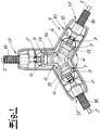
- connection unit according to the invention shows a preferred embodiment of a connecting unit according to the invention with a connector 1 and with three fluid lines 2 connected to the connector.
- the connector 1 and the fluid lines 2 connected thereto may be part of an SCR system of a motor vehicle in the exemplary embodiment and an aqueous urea solution flows through it ,
- the connection unit according to the invention can also be used for other purposes, in particular for fluid media in motor vehicles.
- the connector 1 has three connection ends 3 and a connector section 4 interconnecting the three connection ends 3.
- the fluid line ends 5 of the three fluid lines 2 respectively engage in a connection end 3 of the connector and project in the exemplary embodiment into a middle section 16 of the connector 1.
- the connector points in Embodiment after Fig. 1 a Y-shaped configuration and in each case two of the three connection ends 3 enclose an angle ⁇ of 120 °.
- the embodiment of the connector 1 and the fluid lines 2 connected thereto is according to the exemplary embodiment Fig. 1 as if star-shaped.
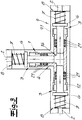
- the operation of the connection unit according to the invention is shown schematically.
- the connector 1 or the connection unit is shown simplified T-shaped. In principle, the connector 1 may also have such a T-shaped configuration.
- a compensation element 6 is connected to the fluid line 2 or to the fluid line end 5 in the region of each fluid line end 5 of the fluid lines 2.
- the compensation elements 6 are designed in the form of compensation flanges, which are rotationally symmetrical with respect to the associated fluid line 2 or the associated fluid line end 5. Tried and tested and in the embodiment, the compensation elements 6 and compensation flanges are each arranged in front of a front end of a terminal end 3 of the connector 1.
- the compensation elements 6 and Kompensationsflansche are firmly connected to the respective fluid line 2, preferably cohesively and / or non-positively connected to the fluid line 2 and in particular welded to the fluid line 2 and to the fluid line end 5.
- a compensation element 6 can be supported on a support stop 8 via a spring element 7.
- the spring element 7 is preferred and formed in the embodiment as a helical spring.
- a Compensating element 6 by increasing the internal volume 15 of the connector portion 4 against the restoring force of the spring element 7 and the coil spring in the direction of the support stop 8 slidably. This has been indicated in the figures by a double arrow.
- a connector housing 1 accommodating the connector 1 is provided.
- the connector housing 9 is according to the embodiment Fig. 1
- the fluid lines 2 each have a line sheath 18, which is preferably formed and in the exemplary embodiment in each case as a corrugated pipe.
- the fluid lines 2 engage with their cable sheath 18 in each case into a housing connection section 17 of the connector housing 9.
- the lead sheaths 18 or the corrugated tubes are preferably fixed in the exemplary embodiment to the ends of the housing connection sections 17 of the connector housing 9.
- the fluid line ends 5 engaging in the connection ends 3 of the connector 1 and the compensation elements 6 respectively connected in the region of the fluid line ends 5 are accommodated in the connector housing 9 together with their associated spring elements 7.
- a support stop 8 for a compensation element 6 is likewise arranged in the connector housing 9 and recommended and in the exemplary embodiment the support stops 8 are part of the connector housing 9.
- the support stops 8 are perpendicular to the longitudinal direction of the associated fluid line 2 or the assigned Fluid line end 5 arranged housing walls 10 of the connector housing 9 is formed.
- the housing walls 10 are integral parts of the connector housing 9.
- the connector housing 9 consists of two half-shells, of which in the Fig. 1 and 2 only a half-shell 9.1 is shown.
- Each half-shell 9.1 preferably has housing wall parts 20, which in the exemplary embodiment complement the housing walls 10 forming the support stops 8 when the half-shell 9.1 is assembled.
- a compensation element 6 protrudes from the outer surface 11 of the associated fluid line end 5 or the associated fluid line 2 and, in the exemplary embodiment, protrudes perpendicularly to the longitudinal direction of the associated fluid line end 5 or the associated fluid line 2.
- the compensation element 6 is preferably designed as a compensation line surrounding the fluid line 2 or the fluid line end 5.
- the spring element 7 is in each case arranged between the compensation element 6 or the compensation flange and the support stop 8. In this case, the compensation element 6 is expediently and outside the connector 1 and placed within the connector housing 9 in the embodiment.
- the fluid lines 2 are designed as heatable fluid lines 2.
- at least one heating component not shown in the figures, in particular a heating wire is preferably wound around the respective fluid line 2.
- the connector 1 is designed as a heatable connector 1.
- a heating element 14 projecting from a fluid line 2 is provided in each case, which protrudes into a fluid channel 12 of the connector 1.
- this heating element 14 is also arranged in the interior 13 of the fluid line 2.
- the heating element 14 is designed as a helical spring.
- This heating element 14 or the coil spring is heated as it were by the heating of the fluid line 2 and the heat is conducted via the heating element 14 or via the coil spring in the fluid channel 12 of the connector 1, so that here also the fluid channel 12 and the interior of the Connector 1 is heated.
- crimp connections 19 can be seen, via which heating components for heating the fluid lines 2 are connected to one another.
- a compensation element 6 or a compensation flange surrounds the heating element 14 respectively provided for heating the connector 1.
Landscapes
- Engineering & Computer Science (AREA)
- General Engineering & Computer Science (AREA)
- Mechanical Engineering (AREA)
- Public Health (AREA)
- Life Sciences & Earth Sciences (AREA)
- Hydrology & Water Resources (AREA)
- Health & Medical Sciences (AREA)
- Water Supply & Treatment (AREA)
- Exhaust Gas After Treatment (AREA)
- Connector Housings Or Holding Contact Members (AREA)
- Branch Pipes, Bends, And The Like (AREA)
- Pipe Accessories (AREA)
- Details Of Connecting Devices For Male And Female Coupling (AREA)
Abstract
Description
- Die Erfindung betrifft ein Verbindungsaggregat mit einem Verbinder und zumindest einer an den Verbinder angeschlossenen Fluidleitung, insbesondere zur Durchleitung einer Harnstofflösung bzw. einer wässrigen Harnstofflösung, wobei der Verbinder zumindest zwei Anschlussenden sowie einen die Anschlussenden miteinander verbindenden Verbinderabschnitt aufweist.
- Verbindungsaggregate der vorstehend beschriebenen Art sind aus der Praxis in unterschiedlichen Ausführungsformen bekannt. Bei Verbindern und Fluidleitungen für die Durchleitung von wässrigen Medien besteht das Problem, dass bei niedrigen Temperaturen das wässrige Medium unter Volumenausdehnung gefriert. Aufgrund dieser Volumenausdehnung bzw. des damit einhergehenden Druckes können die Verbinder und/oder Fluidleitungen beschädigt oder sogar vollständig zerstört werden. Das gilt vor allem auch für Verbinder und Fluidleitungen die zur Durchleitung von wässrigen Harnstofflösungen eingesetzt werden. Solche wässrigen Harnstofflösungen werden bekanntlich im Rahmen sogenannter SCR-Verfahren (Selective Catalytic Reduction) in Kraftfahrzeugen verwendet, um den Stickstoffgehalt von Abgasen zu reduzieren. Vor allem bei solchen wässrigen Harnstofflösungen tritt das oben geschilderte Problem auf. Die wässrige Harnstofflösung gefriert bei niedrigen Temperaturen unter Volumenausdehnung und durch entsprechende Druckerhöhung können Verbinder und Fluidleitungen des SCR-Systems beschädigt oder vollständig zerstört werden. Grundsätzlich ist es bekannt solche Verbinder und/oder die angeschlossenen Fluidleitungen zu beheizen. Nichtsdestoweniger ist eine zusätzliche Abhilfe beim Auftreten eines Gefrieren der Lösungen erwünscht.
- Der Erfindung liegt das technische Problem zugrunde, ein Verbindungsaggregat der eingangs genannten Art anzugeben, bei dem die vorstehend geschilderten Probleme und Nachteile effektiv vermieden werden können.
- Zur Lösung dieses technischen Problems lehrt die Erfindung ein Verbindungsaggregat mit einem Verbinder und zumindest einer an den Verbinder angeschlossenen Fluidleitung, insbesondere zur Durchleitung einer wässrigen Harnstofflösung, wobei der Verbinder zumindest zwei Anschlussenden sowie einen die Anschlussenden miteinander verbindenden Verbinderabschnitt aufweist,
wobei zumindest ein Fluidleitungsende einer Fluidleitung in ein Anschlussende des Verbinders eingreift, wobei im Bereich des Fluidleitungsendes der Fluidleitung zumindest ein Kompensationselement an die Fluidleitung bzw. an das Fluidleitungsende angeschlossen ist, wobei das Kompensationselement über zumindest ein Federelement an zumindest einem Abstützanschlag abstützbar ist
und wobei aufgrund einer Druckerhöhung im Verbinderabschnitt, insbesondere aufgrund der Bildung eines Eisdruckes im Verbinderabschnitt, das Kompensationselement unter Vergrößerung des Innenvolumens des Verbinderabschnittes gegen die Rückstellkraft des Federelementes in Richtung Abstützanschlag verschiebbar ist. - Besondere Bedeutung kommt im Rahmen der Erfindung einem Verbindungsaggregat mit einem Verbinder und zumindest einer an den Verbinder angeschlossenen Fluidleitung zu, welches Verbindungsaggregat im Rahmen eines SCR-Systems in Kraftfahrzeugen für die Durchleitung einer wässrigen Harnstofflösung eingesetzt wird. Das erfindungsgemäße Verbindungsaggregat ist grundsätzlich vor allem für Kraftfahrzeuganwendungen geeignet und kann auch für andere Fluidsysteme in Kraftfahrzeugen eingesetzt werden. - Gemäß besonders bevorzugter Ausführungsform der Erfindung weist der erfindungsgemäße Verbinder zumindest drei Anschlussenden auf und empfohlenermaßen genau drei Anschlussenden. Der Verbinderabschnitt verbindet dabei die zumindest drei Anschlussenden bzw. die drei Anschlussenden miteinander. Eine besonders empfohlene Ausführungsform der Erfindung ist dadurch gekennzeichnet, dass jeweils zwei der drei Anschlussenden des Verbinders einen Winkel von 120° bzw. von etwa 120° einschließen. Bewährtermaßen weist der Verbinder drei solcher Anschlussenden auf und ist bevorzugt Y-förmig ausgestaltet. Grundsätzlich kann der Verbinder aber auch beispielsweise T-förmig ausgebildet sein. Zweckmäßigerweise ist der Verbinder als einstückiges Kunststoffteil, insbesondere als Spritzgussteil ausgeführt.
- Es liegt im Rahmen der Erfindung, dass ein Fluidleitungsende einer an den erfindungsgemäßen Verbinder angeschlossenen Fluidleitung sowohl in das Anschlussende des Verbinders als auch in den Verbinderabschnitt des Verbinders eingreift. Vorzugsweise greift ein Fluidleitungsende einer Fluidleitung an jedem Anschlussende des Verbinders sowohl in das Anschlussende als auch in den Verbinderabschnitt des Verbinders ein. Bei der bevorzugten Ausführungsform mit drei Anschlussenden des Verbinders und bei empfohlenermaßen Y-förmig ausgestaltetem Verbinder ragen die Fluidleitungsenden von drei an die Anschlussenden angeschlossenen Fluidleitungen jeweils in das Anschlussende und in den Verbinderabschnitt des Verbinders, so dass zweckmäßigerweise die Fluidleitungen gleichsam sternförmig von einem Mittelabschnitt des Verbinderabschnittes aus nach außen ragen. Vorzugsweise sind die drei Fluidleitungen bzw. die drei Fluidleitungsenden konzentrisch bezüglich eines Mittelpunktes des Verbinders bzw. des Verbinderabschnittes angeordnet.
- Eine besonders empfohlene Ausführungsform des erfindungsgemäßen Verbindungsaggregates ist dadurch gekennzeichnet, dass an zumindest zwei Anschlussenden - vorzugsweise an jedem Anschlussende - des Verbinders ein Fluidleitungsende einer Fluidleitung in das zugeordnete Anschlussende eingreift und dass im Bereich jedes Fluidleitungsendes zumindest ein Kompensationselement - bevorzugt ein Kompensationselement - an die Fluidleitung bzw. an das Fluidleitungsende angeschlossen ist. Dabei ist zweckmäßigerweise jedes Kompensationselement fest mit der Fluidleitung bzw. mit dem Fluidleitungsende verbunden. Es liegt im Rahmen der Erfindung, dass jedes Kompensationselement über jeweils zumindest ein Federelement - bevorzugt über jeweils ein Federelement - an zumindest einem Abstützanschlag - vorzugsweise an einem Abstützanschlag abstützbar ist bzw. abgestützt wird. Bei dem Federelement handelt es sich nach empfohlener Ausführungsform der Erfindung um eine Schraubenfeder. Grundsätzlich können im Rahmen der Erfindung aber auch andere Arten von Federelementen eingesetzt werden. Ein solches Federelement - bevorzugt eine solche Schraubenfeder - ist bewährtermaßen zwischen Kompensationselement und Abstützanschlag angeordnet und das Federelement bzw. die Schraubenfeder kann mit einem Ende an dem Kompensationselement anliegen und mit dem anderen Ende an dem Abstützanschlag anliegen. Vorzugsweise umgibt das Federelement bzw. die Schraubenfeder die Fluidleitung bzw. das Fluidleitungsende. Es liegt weiterhin im Rahmen der Erfindung, dass der Abstützanschlag kein Bestandteil der Fluidleitung bzw. des Fluidleitungsendes ist und zweckmäßigerweise nicht fest mit der Fluidleitung bzw. mit dem Fluidleitungsende verbunden ist.
- Eine besonders bevorzugte Ausführungsform der Erfindung zeichnet sich dadurch aus, dass ein den Verbinder aufnehmendes Verbindergehäuse vorgesehen ist. Zweckmäßigerweise ist neben dem Verbinder zumindest ein in ein Anschlussende des Verbinders eingreifendes Fluidleitungsende in dem Verbindergehäuse angeordnet und vorzugsweise sind alle in ein Anschlussende des Verbinders eingreifenden Fluidleitungsenden in dem Verbindergehäuse angeordnet. Empfohlenermaßen ist das im Bereich eines Fluidleitungsendes angeschlossene Kompensationselement mitsamt seinem zugeordneten Federelement ebenfalls in dem Verbindergehäuse aufgenommen. Gemäß bevorzugter Ausführungsform der Erfindung ist jedem Anschlussende des Verbinders ein Gehäuseanschlussabschnitt zugeordnet, in welchen die dem Anschlussende des Verbinders zugeordnete Fluidleitung einfasst. Bei einer bevorzugten Ausgestaltung des Verbinders mit drei Anschlussenden weist zweckmäßigerweise auch das Verbindergehäuse drei zugeordnete Gehäuseanschlussabschnitte auf. Bei bewährter Y-förmiger Ausgestaltung des Verbinders ist zweckmäßigerweise auch das Verbindergehäuse Y-förmig ausgebildet. Grundsätzlich kann das Verbindergehäuse auch T-förmig oder ähnlich ausgestaltet sein. - Das Verbindergehäuse kann gemäß einer Ausführungsvariante aus miteinander kombinierbaren Teilschalen, insbesondere aus zwei miteinander kombinierbaren Halbschalen bestehen.
- Es liegt im Übrigen im Rahmen der Erfindung, dass eine an den Verbinder angeschlossene Fluidleitung eine Leitungsumhüllung aufweist, die insbesondere als Wellrohr ausgeführt sein kann. Zweckmäßigerweise greift auch die Leitungsumhüllung - insbesondere ein Wellrohr - einer Fluidleitung ebenfalls in den zugeordneten Gehäuseanschlussabschnitt des Verbindergehäuses ein. Dabei kann die Leitungsumhüllung - insbesondere das Wellrohr - der jeweiligen Fluidleitung an dem Gehäuseanschlussabschnitt des Verbindergehäuses fixiert sein, beispielsweise durch einen Formschluss an dem Gehäuseanschlussabschnitt fixiert sein.
- Eine sehr empfohlene Ausführungsform des erfindungsgemäßen Verbindungsaggregates zeichnet sich dadurch aus, dass ein Abstützanschlag für ein Kompensationselement in dem Verbindergehäuse angeordnet ist und nach besonders bevorzugter Ausführungsform der Erfindung Bestandteil des Verbindergehäuses ist. Zweckmäßigerweise ist ein Abstützanschlag für ein Kompensationselement einstückig mit dem Verbindergehäuse verbunden.
- Es liegt im Rahmen der Erfindung, dass ein Abstützanschlag für ein Kompensationselement als quer, vorzugsweise als senkrecht bzw. als im Wesentlichen senkrecht zur Längsrichtung der zugeordneten Fluidleitung bzw. zur Längsrichtung des zugeordneten Fluidleitungsendes orientiertes Bauelement ausgestaltet ist. Vorzugsweise ist ein Abstützanschlag für ein Kompensationselement als quer, vorzugsweise als senkrecht bzw. als im Wesentlichen senkrecht zur Längsrichtung der zugeordneten Fluidleitung bzw. des zugeordneten Fluidleitungsendes angeordnetes Gehäuseelement - insbesondere als Gehäusewandung - des Verbindergehäuses ausgebildet. Zweckmäßigerweise ist ein Abstützanschlag für ein Kompensationselement in einem Gehäuseanschlussabschnitt des Verbindergehäuses angeordnet und dieser Abstützanschlag ist bevorzugt als quer, zweckmäßigerweise als senkrecht bzw. als im Wesentlichen senkrecht zur Längsrichtung des Gehäuseanschlussabschnittes angeordnetes Gehäuseelement - insbesondere als Gehäusewandung - des Verbindergehäuses ausgestaltet. Wenn das Verbindergehäuse gemäß einer bevorzugten Ausführungsform in Form von zwei Halbschalen ausgebildet ist, weist jede Halbschale zweckmäßigerweise ein Gehäusewandungsteil auf, wobei sich bei Kombination der Halbschalen zwei dieser Gehäusewandungsteile zu einer einen Abstützanschlag bildenden Gehäusewand ergänzen.
- Es liegt im Rahmen der Erfindung, dass ein Kompensationselement fest mit dem zugeordneten Fluidleitungsende bzw. fest mit der zugeordneten Fluidleitung verbunden ist. Zweckmäßigerweise ist dabei das Kompensationselement stoffschlüssig und/oder formschlüssig und/oder kraftschlüssig mit dem zugeordneten Fluidleitungsende bzw. mit der zugeordneten Fluidleitung verbunden. Nach einer empfohlenen Ausführungsform der Erfindung ist ein Kompensationselement mit dem zugeordneten Fluidleitungsende bzw. mit der zugeordneten Fluidleitung verschweißt. Es liegt im Rahmen der Erfindung, dass ein Kompensationselement aus der Außenoberfläche des zugeordneten Fluidleitungsendes bzw. der zugeordneten Fluidleitung herausragt. Eine besonders empfohlene Ausführungsform der Erfindung ist dadurch gekennzeichnet, dass ein Kompensationselement einen quer, insbesondere senkrecht bzw. im Wesentlichen senkrecht zur Längsrichtung des zugeordneten Fluidleitungsendes bzw. der zugeordneten Fluidleitung angeordneten Kompensationsflansch aufweist bzw. dass das Kompensationselement aus einem solchen Kompensationsflansch besteht bzw. im Wesentlichen besteht. Dieser Kompensationsflansch ist zweckmäßigerweise über das zumindest eine Federelement - vorzugsweise über die zumindest eine Schraubenfeder - an dem Abstützanschlag abstützbar. Zweckmäßigerweise ist der Kompensationsflansch rotationssymmetrisch bezüglich der zugeordneten Fluidleitung bzw. des zugeordneten Fluidleitungsendes ausgestaltet. Es liegt im Rahmen der Erfindung, dass das Kompensationselement - bevorzugt der Kompensationsflansch - außerhalb des Verbinders und innerhalb des Verbindergehäuses angeordnet ist. Zweckmäßigerweise ist das Kompensationselement bzw. der Kompensationsflansch unmittelbar bzw. mit geringem Abstand vor dem Ende eines Verbinderabschnittes des Verbinders angeordnet. Es liegt im Rahmen der Erfindung, dass sich das Kompensationselement bzw. der Kompensationsflansch an dem Stirnende eines Verbinderabschnittes des Verbinders abstützen kann.
- Bei einer Druckerhöhung in dem Verbinder bzw. in dem Mittelabschnitt des Verbinders und insbesondere bei Ausbildung eines Eisdruckes in dem Verbinder bzw. in dem Mittelabschnitt des Verbinders wird ein in den Verbinder bzw. bis zum Mittelabschnitt des Verbinders ragendes Fluidleitungsende gleichsam aus dem Verbinder bzw. aus dem zugeordneten Verbinderabschnitt herausgedrückt und dadurch kann das an dem jeweiligen Fluidleitungsende angeschlossene Kompensationselement auf das Federelement bzw. auf die Schraubenfeder einwirken, so dass das Fluidleitungsende bzw. das daran angeschlossene Kompensationselement gegen die Rückstellkraft des Federelementes bewegt wird. Auf diese Weise kommt es zu einer Vergrößerung des Innenvolumens in dem Verbinder bzw. in dem jeweiligen Verbinderabschnitt.
- Bei Nachlassen des Druckes im Innenraum des Verbinders kann entsprechend unter Einwirkung der Rückstellkraft des Federelementes das Kompensationselement und das jeweilige Fluidleitungsende in seine ursprüngliche Position zurückgelangen.
- Eine besonders bevorzugte Ausführungsform der Erfindung ist dadurch gekennzeichnet, dass eine an den Verbinder angeschlossene Fluidleitung als beheizbare Fluidleitung ausgebildet ist. Dabei kann die Fluidleitung durch zumindest eine um die Fluidleitung gewickelte Heizkomponente - beispielsweise durch zumindest einen um die Fluidleitung gewickelten Heizdraht - beheizt werden. Die Heizkomponente bzw. der Heizdraht kann dabei spiralförmig um die Fluidleitung gewickelt sein. Weiterhin liegt es im Rahmen der Erfindung, dass der Verbinder als beheizbarer Verbinder ausgebildet ist. Auch der Verbinder kann grundsätzlich mittels eines Heizelementes beheizt werden, das um den Verbinder bzw. um die Verbinderabschnitte des Verbinders gewickelt ist. Nach einer besonders bevorzugten Ausführungsform der Erfindung ragt von einer beheizten Fluidleitung her ein Heizelement in das Innere des Verbinders bzw. in das Innere eines Verbinderabschnittes. Bei diesem Heizelement kann es sich insbesondere um eine Schraubenfeder handeln, die sich von der beheizten Fluidleitung aus in das Innere des Verbinders bzw. in das Innere eines Verbinderabschnittes des Verbinders erstreckt. Dabei wird das in die Fluidleitung ragende Heizelement - insbesondere die in die Fluidleitung ragende Schraubenfeder - aufgrund der Beheizung der Fluidleitung erwärmt und das weiterhin in den Verbinderabschnitt des Verbinders ragende Heizelement - insbesondere die Schraubenfeder - leitet gleichsam die Wärme zur Beheizung des Verbinders in den Verbinderabschnitt weiter. - Nach einer empfohlenen Ausführungsform umgibt ein Kompensationselement ein zur Beheizung des Verbinders vorgesehenes Heizelement. Das gilt insbesondere für das vorstehend beschriebenen Heizelement, das sich ausgehend von der beheizten Fluidleitung in den Verbinder erstreckt bzw. in den Verbinderabschnitt des Verbinders erstreckt.
- Der Erfindung liegt die Erkenntnis zugrunde, dass mit einem erfindungsgemäßen Verbindungsaggregat insbesondere temperaturbedingte Volumenausdehnungen eines fluiden Mediums aufgrund des erfindungsgemäß vorgesehenen Kompensationselementes bzw. aufgrund der erfindungsgemäß vorgesehenen Kompensationselemente einfach, funktionssicher und effektiv ausgeglichen werden können. Beschädigungen der Bauelemente des erfindungsgemäßen Verbindungsaggregates können problemlos vermieden werden und es findet bei Volumenausdehnungen bzw. bei Auftreten eines Eisdruckes eine gleichsam schonende Beaufschlagung der einzelnen Bauelemente statt. Problemlos können die beteiligten Baukomponenten bei Nachlassen des entsprechenden Druckes bzw. bei Nachlassen der Volumenausdehnungen reversibel wieder in ihre Ausgangszustände zurückkehren. Das erfindungsgemäße Verbindungsaggregat ist vor allem für SCR-Systeme in Kraftfahrzeugen geeignet, die mit wässrigen Harnstofflösungen betrieben werden. Es ist auch hervorzuheben, dass ein erfindungsgemäßes Verbindungsaggregat relativ wenig komplex und wenig aufwendig aufgebaut ist und mit verhältnismäßig geringen Kosten realisierbar ist.
- Nachfolgend wird die Erfindung anhand einer lediglich ein Ausführungsbeispiel darstellenden Zeichnung näher erläutert. Es zeigen in schematischer Darstellung:
- Fig. 1
- eine Draufsicht auf ein erfindungsgemäßes Verbindungsaggregat im Schnitt,
- Fig. 2
- einen vergrößerten Ausschnitt A aus
Fig. 1 und - Fig. 3
- eine schematische Darstellung der Funktionsweise des erfindungsgemäßen Verbindungsaggregates.
- Die Figuren zeigen eine bevorzugte Ausführungsform eines erfindungsgemäßen Verbindungsaggregates mit einem Verbinder 1 und mit drei an den Verbinder angeschlossenen Fluidleitungen 2. Der Verbinder 1 und die daran angeschlossenen Fluidleitungen 2 mögen im Ausführungsbeispiel Bestandteil eines SCR-Systems eines Kraftfahrzeuges sein und werden von einer wässrigen Harnstofflösung durchströmt. Grundsätzlich kann das erfindungsgemäße Verbindungsaggregat aber auch für andere Anwendungszwecke eingesetzt werden, und zwar insbesondere für fluide Medien in Kraftfahrzeugen.
- Im Ausführungsbeispiel weist der Verbinder 1 drei Anschlussenden 3 auf sowie einen die drei Anschlussenden 3 miteinander verbindenden Verbinderabschnitt 4. Die Fluidleitungsenden 5 der drei Fluidleitungen 2 greifen jeweils in ein Anschlussende 3 des Verbinders ein und ragen im Ausführungsbeispiel bis in einen Mittelabschnitt 16 des Verbinders 1. Der Verbinder weist im Ausführungsbeispiel nach
Fig. 1 eine Y-förmige Ausgestaltung auf und jeweils zwei der drei Anschlussenden 3 schließen einen Winkel α von 120° ein. Die Ausgestaltung des Verbinders 1 und der daran angeschlossenen Fluidleitungen 2 ist im Ausführungsbeispiel gemäßFig. 1 gleichsam sternförmig. - In derFig. 3 ist die Funktionsweise des erfindungsgemäßen Verbindungsaggregates schematisch dargestellt. Hier ist der Verbinder 1 bzw. das Verbindungsaggregat vereinfacht T-förmig gezeigt. Grundsätzlich kann der Verbinder 1 auch eine solche T-förmige Ausgestaltung aufweisen. - Vorzugsweise und im Ausführungsbeispiel ist im Bereich jedes Fluidleitungsendes 5 der Fluidleitungen 2 jeweils ein Kompensationselement 6 an die Fluidleitung 2 bzw. an das Fluidleitungsende 5 angeschlossen. Zweckmäßigerweise und im Ausführungsbeispiel sind die Kompensationselemente 6 in Form von Kompensationsflanschen ausgebildet, die bezüglich der zugeordneten Fluidleitung 2 bzw. des zugeordneten Fluidleitungsendes 5 rotationssymmetrisch ausgeführt sind. Bewährtermaßen und im Ausführungsbeispiel sind die Kompensationselemente 6 bzw. Kompensationsflansche jeweils vor einem Stirnende eines Anschlussendes 3 des Verbinders 1 angeordnet. Empfohlenermaßen und im Ausführungsbeispiel sind die Kompensationselemente 6 bzw. Kompensationsflansche fest mit der jeweiligen Fluidleitung 2 verbunden, bevorzugt stoffschlüssig und/oder kraftschlüssig mit der Fluidleitung 2 verbunden und insbesondere an die Fluidleitung 2 bzw. an das Fluidleitungsende 5 angeschweißt.
- Erfindungsgemäß ist ein Kompensationselement 6 über ein Federelement 7 an einem Abstützanschlag 8 abstützbar. Das Federelement 7 ist bevorzugt und im Ausführungsbeispiel als Schraubenfeder ausgebildet. - Aufgrund einer Druckerhöhung bzw. Volumenerhöhung im Verbinderabschnitt 4, insbesondere aufgrund der Bildung eines Eisdruckes im Verbinderabschnitt 4, ist ein Kompensationselement 6 unter Vergrößerung des Innenvolumens 15 des Verbinderabschnittes 4 gegen die Rückstellkraft des Federelementes 7 bzw. der Schraubenfeder in Richtung Abstützanschlag 8 verschiebbar. Das ist in den Figuren durch einen Doppelpfeil angedeutet worden.
- Zweckmäßigerweise und im Ausführungsbeispiel ist ein den Verbinder 1 aufnehmendes Verbindergehäuse 9 vorgesehen. Das Verbindergehäuse 9 ist im Ausführungsbeispiel gemäß
Fig. 1 wie der Verbinder 1 Y-förmig ausgestaltet und jedem Anschlussende 3 des Verbinders 1 ist zweckmäßigerweise und im Ausführungsbeispiel ein Gehäuseanschlussabschnitt 17 zugeordnet. Bewährtermaßen und im Ausführungsbeispiel weisen die Fluidleitungen 2 jeweils eine Leitungsumhüllung 18 auf, die bevorzugt und im Ausführungsbeispiel jeweils als Wellrohr ausgebildet ist. Vorzugsweise und im Ausführungsbeispiel greifen die Fluidleitungen 2 mit ihrer Leitungsumhüllung 18 jeweils in einen Gehäuseanschlussabschnitt 17 des Verbindergehäuses 9 ein. Dabei sind bevorzugt und im Ausführungsbeispiel die Leitungsumhüllungen 18 bzw. die Wellrohre formschlüssig an den Enden der Gehäuseanschlussabschnitte 17 des Verbindergehäuses 9 fixiert. - Zweckmäßigerweise und im Ausführungsbeispiel sind die in die Anschlussenden 3 des Verbinders 1 eingreifenden Fluidleitungsenden 5 sowie die im Bereich der Fluidleitungsenden 5 jeweils angeschlossenen Kompensationselemente 6 mitsamt ihren zugeordneten Federelementen 7 in dem Verbindergehäuse 9 aufgenommen. Vorzugsweise und im Ausführungsbeispiel ist jeweils ein Abstützanschlag 8 für ein Kompensationselement 6 ebenfalls in dem Verbindergehäuse 9 angeordnet und empfohlenermaßen und im Ausführungsbeispiel sind die Abstützanschläge 8 Bestandteil des Verbindergehäuses 9. Dabei sind bevorzugt und im Ausführungsbeispiel die Abstützanschläge 8 als senkrecht zur Längsrichtung der zugeordneten Fluidleitung 2 bzw. des zugeordneten Fluidleitungsendes 5 angeordnete Gehäusewandungen 10 des Verbindergehäuses 9 ausgebildet. Zweckmäßigerweise und im Ausführungsbeispiel sind dabei die Gehäusewandungen 10 einstückige Bestandteile des Verbindergehäuses 9. - Bevorzugt und im Ausführungsbeispiel besteht das Verbindergehäuse 9 aus zwei Halbschalen, von denen in den
Fig. 1 und2 lediglich eine Halbschale 9.1 dargestellt ist. Jede Halbschale 9.1 weist bevorzugt und im Ausführungsbeispiel Gehäusewandungsteile 20 auf, die sich beim Zusammenfügen der Halbschale 9.1 zu den die Abstützanschläge 8 bildenden Gehäusewandungen 10 ergänzen. - In den Figuren ist erkennbar, dass ein Kompensationselement 6 aus der Außenoberfläche 11 des zugeordneten Fluidleitungsendes 5 bzw. der zugeordneten Fluidleitung 2 herausragt und zwar bevorzugt und im Ausführungsbeispiel senkrecht zur Längsrichtung des zugeordneten Fluidleitungsendes 5 bzw. der zugeordneten Fluidleitung 2 herausragt. Es wurde bereits oben dargelegt, dass das Kompensationselement 6 bevorzugt als die Fluidleitung 2 bzw. das Fluidleitungsende 5 umgebender Kompensationsflansch ausgebildet ist. Das Federelement 7 ist jeweils zwischen dem Kompensationselement 6 bzw. dem Kompensationsflansch und dem Abstützanschlag 8 angeordnet. Dabei ist das Kompensationselement 6 zweckmäßigerweise und im Ausführungsbeispiel außerhalb des Verbinders 1 und innerhalb des Verbindergehäuses 9 platziert.
- Bei einer Volumenerhöhung bzw. Druckerhöhung im Verbinderabschnitt 4 des Verbinders 1 wird das jeweilige Fluidleitungsende 5 gleichsam aus dem Verbinder 1 herausgedrückt, wobei das daran angeschlossene Kompensationselement 6 gegen die Rückstellkraft des Federelementes 7 in Richtung Abstützanschlag 8 verschoben bzw. gedrückt wird. Das ist in
Fig. 3 sehr schematisch dargestellt. Hier ist weiterhin erkennbar, dass bevorzugt und im Ausführungsbeispiel O-Ringe 21 zwischen den verschiebbaren Fluidleitungsenden 5 und den Anschlussenden 3 des Verbinders 1 abdichten. - Nach empfohlener Ausführungsform und im Ausführungsbeispiel sind die Fluidleitungen 2 als beheizbare Fluidleitungen 2 ausgebildet. Vorzugsweise ist dazu zumindest eine in den Figuren nicht dargestellte Heizkomponente, insbesondere ein Heizdraht um die jeweilige Fluidleitung 2 gewickelt. Vorzugsweise und im Ausführungsbeispiel ist auch der Verbinder 1 als beheizbarer Verbinder 1 ausgeführt. Zweckmäßigerweise ist dazu jeweils ein aus einer Fluidleitung 2 herausragendes Heizelement 14 vorgesehen, das in einen Fluidkanal 12 des Verbinders 1 hineinragt. Zweckmäßigerweise und im Ausführungsbeispiel ist dieses Heizelement 14 auch in dem Innenraum 13 der Fluidleitung 2 angeordnet. Vorzugsweise und im Ausführungsbeispiel ist das Heizelement 14 als Schraubenfeder ausgebildet. Dieses Heizelement 14 bzw. die Schraubenfeder wird gleichsam durch die Beheizung der Fluidleitung 2 beheizt und die Wärme wird über das Heizelement 14 bzw. über die Schraubenfeder in den Fluidkanal 12 des Verbinders 1 geleitet, so dass hier auch der Fluidkanal 12 bzw. der Innenraum des Verbinders 1 beheizt wird. Im Ausführungsbeispiel sind im Übrigen Crimpverbindungen 19 erkennbar, über die Heizkomponenten zur Beheizung der Fluidleitungen 2 miteinander verbunden sind. Insbesondere in der
Fig. 2 ist erkennbar, dass nach bevorzugter Ausführungsform und im Ausführungsbeispiel ein Kompensationselement 6 bzw. ein Kompensationsflansch das für die Beheizung des Verbinders 1 jeweils vorgesehene Heizelement 14 umgibt.
Claims (15)
- Verbindungsaggregat mit einem Verbinder (1) und zumindest einer an den Verbinder (1) angeschlossenen Fluidleitung (2), insbesondere zur Durchleitung einer wässrigen Harnstofflösung, wobei der Verbinder (1) zumindest zwei Anschlussenden (3) sowie einen die Anschlussenden (3) miteinander verbindenden Verbinderabschnitt (4) aufweist,
wobei zumindest ein Fluidleitungsende (5) einer Fluidleitung (2) zumindest in ein Anschlussende (3) des Verbinders (1) eingreift, wobei im Bereich des Fluidleitungsendes (5) der Fluidleitung (2) zumindest ein Kompensationselement (6) an die Fluidleitung (2) bzw. an das Fluidleitungsende (5) angeschlossen ist, wobei das Kompensationselement (6) über zumindest ein Federelement (7) an zumindest einem Abstützanschlag (8) abstützbar ist
und wobei aufgrund einer Druckerhöhung im Verbinderabschnitt (4), insbesondere aufgrund der Bildung eines Eisdruckes im Verbinderabschnitt (4), das Kompensationselement (6) unter Vergrößerung des Innenvolumens (15) des Verbinderabschnittes (4) gegen die Rückstellkraft des Federelementes (7) in Richtung Abstützanschlag (8) verschiebbar ist. - Verbindungsaggregat nach Anspruch 1, wobei der Verbinder (1) zumindest drei Anschlussenden (3), insbesondere drei Anschlussenden (3) aufweist, wobei der Verbinderabschnitt (4) die zumindest drei Anschlussenden (3) miteinander verbindet.
- Verbindungsaggregat nach Anspruch 2, wobei jeweils zwei der drei Anschlussenden (3) einen Winkel von 120° bzw. von etwa 120° einschließen.
- Verbindungsaggregat nach einem der Ansprüche 1 bis 3, wobei an zumindest zwei Anschlussenden (3), vorzugsweise an jedem Anschlussende (3) des Verbinders (1) ein Fluidleitungsende (5) einer Fluidleitung (2) in das Anschlussende (3) eingreift, wobei im Bereich jedes Fluidleitungsendes (5) zumindest ein Kompensationselement (6) an die Fluidleitung (2) bzw. an das Fluidleitungsende (5) angeschlossen ist und wobei jedes Kompensationselement (6) über jeweils zumindest ein Federelement (7) an zumindest einem Abstützanschlag (8) abstützbar ist bzw. abgestützt ist.
- Verbindungsaggregat nach einem der Ansprüche 1 bis 4, wobei ein den Verbinder (1) aufnehmendes Verbindergehäuse (9) vorgesehen ist und wobei zumindest ein in ein Anschlussende (3) des Verbinders (1) eingreifendes Fluidleitungsende (5) sowie das im Bereich des Fluidleitungsendes (5) angeschlossene Kompensationselement (6) mitsamt zugeordnetem Federelement (7) in dem Verbindergehäuse (9) aufgenommen sind.
- Verbindungsaggregat nach Anspruch 5, wobei zumindest ein Abstützanschlag (8) für zumindest ein Kompensationselement (6) in dem Verbindergehäuse (9) angeordnet ist und vorzugsweise Bestandteil des Verbindergehäuses (9) ist.
- Verbindungsaggregat nach einem der Ansprüche 5 oder 6, wobei ein Abstützanschlag (8) als quer, vorzugsweise als senkrecht bzw. als im Wesentlichen senkrecht zur Längsrichtung der zugeordneten Fluidleitung (2) bzw. des zugeordneten Fluidleitungsendes (5) angeordnetes Gehäuseelement - insbesondere als Gehäusewandung (10) - des Verbindergehäuses (9) ausgebildet ist.
- Verbindungsaggregat nach einem der Ansprüche 1 bis 7, wobei das Kompensationselement (6) fest mit dem zugeordneten Fluidleitungsende (5) bzw. mit der zugeordneten Fluidleitung (2) verbunden ist.
- Verbindungsaggregat nach Anspruch 8, wobei das Kompensationselement (6) stoffschlüssig und/oder formschlüssig und/oder kraftschlüssig mit dem zugeordneten Fluidleitungsende (5) bzw. mit der zugeordneten Fluidleitung (2) verbunden ist.
- Verbindungsaggregat nach einem der Ansprüche 1 bis 9, wobei das Kompensationselement (6) aus der Außenoberfläche (11) des zugeordneten Fluidleitungsendes (5) bzw. der zugeordneten Fluidleitung (2) herausragt.
- Verbindungsaggregat nach einem der Ansprüche 1 bis 10, wobei das Kompensationselement (6) einen quer, insbesondere senkrecht bzw. im Wesentlichen senkrecht zur Längsrichtung des zugeordneten Fluidleitungsendes (5) bzw. der zugeordneten Fluidleitung (2) angeordneten Kompensationsflansch aufweist, welcher Kompensationsflansch über das zumindest eine Federelement (7) an dem Abstützanschlag (8) abstützbar ist bzw. abgestützt wird.
- Verbindungsaggregat nach einem der Ansprüche 1 bis 11, wobei das Kompensationselement (6) außerhalb des Verbinders (1) und innerhalb des Verbindergehäuses (9) angeordnet ist.
- Verbindungsaggregat nach einem der Ansprüche 1 bis 12, wobei die Fluidleitung (2) als beheizbare Fluidleitung (2) ausgebildet ist und/oder wobei der Verbinder (1) als beheizbarer Verbinder (1) ausgebildet ist.
- Verbindungsaggregat nach einem der Ansprüche 1 bis 13, wobei der Verbinder (1) mit zumindest einem in einen Fluidkanal (12) des Verbinders (1) und/oder in den Innenraum (13) eines Fluidleitungsendes (5) hineinragenden Heizelement (14) beheizbar ist bzw. beheizt wird.
- Verbindungsaggregat nach Anspruch 14, wobei das/ein Kompensationselement (6) ein zur Beheizung des Verbinders (1) vorgesehenes Heizelement (14) umgibt.
Priority Applications (2)
| Application Number | Priority Date | Filing Date | Title |
|---|---|---|---|
| JP2018037335A JP6791896B2 (ja) | 2017-03-06 | 2018-03-02 | 接続ユニット |
| US15/913,282 US10851932B2 (en) | 2017-03-06 | 2018-03-06 | Connection unit |
Applications Claiming Priority (1)
| Application Number | Priority Date | Filing Date | Title |
|---|---|---|---|
| DE202017101274.3U DE202017101274U1 (de) | 2017-03-06 | 2017-03-06 | Verbindungsaggregat |
Publications (2)
| Publication Number | Publication Date |
|---|---|
| EP3372736A1 true EP3372736A1 (de) | 2018-09-12 |
| EP3372736B1 EP3372736B1 (de) | 2020-10-07 |
Family
ID=58545606
Family Applications (1)
| Application Number | Title | Priority Date | Filing Date |
|---|---|---|---|
| EP17210440.8A Active EP3372736B1 (de) | 2017-03-06 | 2017-12-22 | Verbindungsaggregat |
Country Status (7)
| Country | Link |
|---|---|
| US (1) | US10851932B2 (de) |
| EP (1) | EP3372736B1 (de) |
| JP (1) | JP6791896B2 (de) |
| KR (1) | KR102481769B1 (de) |
| CN (1) | CN108533863B (de) |
| DE (1) | DE202017101274U1 (de) |
| MX (1) | MX2018002782A (de) |
Families Citing this family (10)
| Publication number | Priority date | Publication date | Assignee | Title |
|---|---|---|---|---|
| FR3050356B1 (fr) * | 2016-04-18 | 2018-05-04 | Saipem S.A. | Installation electrique pour systeme de chauffage electrique par tracage d'une conduite metallique de transport de fluides et procede de chauffage electrique par tracage d'une telle conduite |
| DE202017104371U1 (de) * | 2017-07-21 | 2018-10-23 | Voss Automotive Gmbh | SCR-Verbindungsstelle |
| CN107524878B (zh) * | 2017-10-09 | 2023-09-19 | 李继前 | 具有导电功能的导管组件 |
| DE102018103571A1 (de) * | 2018-02-16 | 2019-08-22 | Voss Automotive Gmbh | Verbindungsanordnung zum Verbinden von beheizbaren Fluidleitungen |
| DE102018104739A1 (de) * | 2018-03-01 | 2019-09-05 | Norma Germany Gmbh | Leitungsverbinder |
| DE102018107004B4 (de) * | 2018-03-23 | 2025-11-06 | Voss Automotive Gmbh | Beheizte Medienleitung mit Fixierteil |
| DE102018107005A1 (de) * | 2018-03-23 | 2019-09-26 | Voss Automotive Gmbh | Beheizte Medienleitung |
| DE102018117056A1 (de) | 2018-07-13 | 2020-01-16 | Voss Automotive Gmbh | Verbindungsanordnung, insbesondere zum Durchführen von wässrigen Harnstofflösungen |
| IT201900007010A1 (it) * | 2019-05-20 | 2020-11-20 | Hutchinson Srl | Linea per un fluido riscaldabile comprendente più condotti, in particolare per un sistema SCR o un sistema di iniezione ad acqua, e processo di assemblaggio. |
| US12209524B2 (en) | 2022-08-23 | 2025-01-28 | Caterpillar Inc. | Exhaust fluid injector assembly |
Citations (4)
| Publication number | Priority date | Publication date | Assignee | Title |
|---|---|---|---|---|
| US20040195828A1 (en) * | 2003-03-14 | 2004-10-07 | Tony Holmes | Water distribution fitting and distribution system |
| DE102007016789A1 (de) * | 2007-04-05 | 2008-10-09 | Eichenauer Heizelemente Gmbh & Co. Kg | Beheizbares Anschlussstück für eine Fluidleitung |
| DE202007013316U1 (de) * | 2007-09-21 | 2009-02-12 | Voss Automotive Gmbh | Anschlussvorrichtung für Medienleitungen |
| DE102009040012A1 (de) * | 2008-10-17 | 2010-05-20 | Rehau Ag + Co | Verbindungsanordnung zur Verbindung von Medienleitungen |
Family Cites Families (17)
| Publication number | Priority date | Publication date | Assignee | Title |
|---|---|---|---|---|
| US2667899A (en) * | 1951-08-10 | 1954-02-02 | Willard L Kingston | Expansion joint for pipe lines |
| US4123092A (en) * | 1976-09-08 | 1978-10-31 | Colbert Jr Thomas E | Contraction resistant coupling for pipe lines carrying gases or fluids |
| US5101213A (en) * | 1989-01-23 | 1992-03-31 | Harada Kogyo Kabushiki Kaisha | Screw type coupling device and an antenna installation device using the same |
| DE4124204A1 (de) * | 1991-07-20 | 1993-01-21 | Deere & Co | Verbindung zwischen abgasrohr und endrohr |
| JPH05149489A (ja) * | 1991-11-25 | 1993-06-15 | Showa Alum Corp | 低温流体流通管の接続装置 |
| ATE507026T1 (de) * | 2001-10-22 | 2011-05-15 | Air Prod & Chem | Linearbetätigte kryofluidverbindung (lacc) für fertigungsmaschinen |
| US20040019828A1 (en) * | 2002-07-25 | 2004-01-29 | Gergen Joseph P. | Method and apparatus for debugging a data processing system |
| SE0401557D0 (sv) * | 2004-06-15 | 2004-06-15 | Volvo Lastvagnar Ab | Elektrisk uppvärmningsbart kopplingsstycke samt inkapslad vätskeslang med elektriskt uppvärmningsbart kopplingsstycke |
| EP1860134B1 (de) * | 2005-03-18 | 2015-05-27 | Kuraray Co., Ltd. | Halbaromatisches polyamidharz |
| WO2007112533A1 (en) * | 2006-04-05 | 2007-10-11 | Donald George Stewart | Adjustable sprinkler head riser |
| DE202007010502U1 (de) * | 2007-07-26 | 2008-11-27 | Voss Automotive Gmbh | Konfektionierte Medienleitung |
| IT1391595B1 (it) * | 2008-10-30 | 2012-01-11 | Caleffi Spa | Dispositivo valvolare antigelo per impianti idraulici e/o di accumulo di acqua |
| US9568134B2 (en) * | 2011-08-05 | 2017-02-14 | Eaton Corporation | Fluid conveyence system connector |
| DE102013000588A1 (de) * | 2013-01-16 | 2014-07-17 | Voss Automotive Gmbh | Konfektionierte beheizbare Medienleitung, Verwendung einer solchen sowie Verfahren zum Herstellen einer solchen |
| KR20160048871A (ko) * | 2013-08-29 | 2016-05-04 | 알피니티, 엘엘씨 | 폴리머 인서트 위에 uv 경화성 재료를 오버몰딩하기 위한 방법 및 장치 |
| DE102014108494A1 (de) * | 2014-06-17 | 2015-12-17 | Norma Germany Gmbh | Fluidleitung |
| US20170023163A1 (en) * | 2015-07-20 | 2017-01-26 | Norma U.S. Holding Llc | Heated Connector Assembly |
-
2017
- 2017-03-06 DE DE202017101274.3U patent/DE202017101274U1/de not_active Expired - Lifetime
- 2017-12-22 EP EP17210440.8A patent/EP3372736B1/de active Active
-
2018
- 2018-03-02 JP JP2018037335A patent/JP6791896B2/ja active Active
- 2018-03-05 KR KR1020180025900A patent/KR102481769B1/ko active Active
- 2018-03-05 MX MX2018002782A patent/MX2018002782A/es unknown
- 2018-03-06 CN CN201810183272.8A patent/CN108533863B/zh active Active
- 2018-03-06 US US15/913,282 patent/US10851932B2/en active Active
Patent Citations (4)
| Publication number | Priority date | Publication date | Assignee | Title |
|---|---|---|---|---|
| US20040195828A1 (en) * | 2003-03-14 | 2004-10-07 | Tony Holmes | Water distribution fitting and distribution system |
| DE102007016789A1 (de) * | 2007-04-05 | 2008-10-09 | Eichenauer Heizelemente Gmbh & Co. Kg | Beheizbares Anschlussstück für eine Fluidleitung |
| DE202007013316U1 (de) * | 2007-09-21 | 2009-02-12 | Voss Automotive Gmbh | Anschlussvorrichtung für Medienleitungen |
| DE102009040012A1 (de) * | 2008-10-17 | 2010-05-20 | Rehau Ag + Co | Verbindungsanordnung zur Verbindung von Medienleitungen |
Also Published As
| Publication number | Publication date |
|---|---|
| JP2018151068A (ja) | 2018-09-27 |
| KR20180102019A (ko) | 2018-09-14 |
| US10851932B2 (en) | 2020-12-01 |
| US20180252345A1 (en) | 2018-09-06 |
| KR102481769B1 (ko) | 2022-12-26 |
| MX2018002782A (es) | 2018-11-09 |
| CN108533863A (zh) | 2018-09-14 |
| DE202017101274U1 (de) | 2017-03-24 |
| CN108533863B (zh) | 2021-08-17 |
| EP3372736B1 (de) | 2020-10-07 |
| JP6791896B2 (ja) | 2020-11-25 |
Similar Documents
| Publication | Publication Date | Title |
|---|---|---|
| EP3372736A1 (de) | Verbindungsaggregat | |
| DE2802109C2 (de) | Bohrloch-Zentrierstück, Manschettenhälfte dafür und Verfahren zur Herstellung eines solchen Zentrierstücks | |
| DE102013106217A1 (de) | Leitungsverbinder sowie Leitungssatz für fluidische Medien | |
| DE102011012769A1 (de) | Hochleistungs-Durchlauferhitzer und Verfahren zu dessen Herstellung | |
| DE102010032189A1 (de) | Beheizbare Medienleitung und Verfahren zu deren Herstellung | |
| WO2018019469A1 (de) | Kraftfahrzeug-fluidleitung | |
| EP3431855B1 (de) | Scr-verbindungsstelle | |
| EP2455645B1 (de) | Verbinder für die Verbindung von zumindest zwei Aufnahmeelementen für ein fluides Medium | |
| DE102008006323A1 (de) | Reduktionsmittelversorgungssystem für einen Abgasreinigungskatalysator eines Verbrennungsmotors und Steckverbindung zum Anschließen von beheizbaren Flüssigkeitsleitungen | |
| WO2012143135A2 (de) | Medienleitung | |
| DE202012008100U1 (de) | Vorrichtung zum schwingungsentkoppelten Verbinden zweier Einrichtungen einer Abgasanlage | |
| DE202015104387U1 (de) | Medienleitung | |
| DE202013101265U1 (de) | Medienleitung | |
| DE102015120508A1 (de) | Verbindungsanordnung für ein Kühlmittelsystem und Verfahren zur Herstellung einer Verbindungsanordnung | |
| DE102016111336A1 (de) | Gehäuseverbindung | |
| DE202014003776U1 (de) | Kunststoffrohr | |
| WO2020011484A1 (de) | Verbindungsanordnung, insbesondere zum durchführen von wässrigen harnstofflösungen | |
| DE102007042841A1 (de) | Anschlussvorrichtung | |
| EP3133329B1 (de) | Beheizbare kraftfahrzeugrohrleitung und verfahren zur herstellung einer beheizbaren kraftfahrzeugrohrleitung | |
| DE102007063641B4 (de) | Verbindungsanordnung für den Installationsbereich | |
| DE202007007125U1 (de) | Heizmittel zur Erwärmung eines Fluids | |
| DE202008003270U1 (de) | Baugruppe zur Aufnahme und Erwärmung einer Harnstoff-Wasser-Lösung | |
| EP3498994B1 (de) | Heizeinrichtung zum beheizen von flüssigkeiten in einem reservoir, wie einem tank oder einem behälter, eines fahrzeugs | |
| DE19548719C1 (de) | Flexible Steckverbindung für Abgasleitungen | |
| DE10228485B4 (de) | Rohranordnung |
Legal Events
| Date | Code | Title | Description |
|---|---|---|---|
| PUAI | Public reference made under article 153(3) epc to a published international application that has entered the european phase |
Free format text: ORIGINAL CODE: 0009012 |
|
| STAA | Information on the status of an ep patent application or granted ep patent |
Free format text: STATUS: THE APPLICATION HAS BEEN PUBLISHED |
|
| STAA | Information on the status of an ep patent application or granted ep patent |
Free format text: STATUS: REQUEST FOR EXAMINATION WAS MADE |
|
| AK | Designated contracting states |
Kind code of ref document: A1 Designated state(s): AL AT BE BG CH CY CZ DE DK EE ES FI FR GB GR HR HU IE IS IT LI LT LU LV MC MK MT NL NO PL PT RO RS SE SI SK SM TR |
|
| AX | Request for extension of the european patent |
Extension state: BA ME |
|
| 17P | Request for examination filed |
Effective date: 20180830 |
|
| RBV | Designated contracting states (corrected) |
Designated state(s): AL AT BE BG CH CY CZ DE DK EE ES FI FR GB GR HR HU IE IS IT LI LT LU LV MC MK MT NL NO PL PT RO RS SE SI SK SM TR |
|
| GRAP | Despatch of communication of intention to grant a patent |
Free format text: ORIGINAL CODE: EPIDOSNIGR1 |
|
| STAA | Information on the status of an ep patent application or granted ep patent |
Free format text: STATUS: GRANT OF PATENT IS INTENDED |
|
| INTG | Intention to grant announced |
Effective date: 20200430 |
|
| GRAS | Grant fee paid |
Free format text: ORIGINAL CODE: EPIDOSNIGR3 |
|
| GRAA | (expected) grant |
Free format text: ORIGINAL CODE: 0009210 |
|
| STAA | Information on the status of an ep patent application or granted ep patent |
Free format text: STATUS: THE PATENT HAS BEEN GRANTED |
|
| AK | Designated contracting states |
Kind code of ref document: B1 Designated state(s): AL AT BE BG CH CY CZ DE DK EE ES FI FR GB GR HR HU IE IS IT LI LT LU LV MC MK MT NL NO PL PT RO RS SE SI SK SM TR |
|
| REG | Reference to a national code |
Ref country code: GB Ref legal event code: FG4D Free format text: NOT ENGLISH |
|
| REG | Reference to a national code |
Ref country code: AT Ref legal event code: REF Ref document number: 1321287 Country of ref document: AT Kind code of ref document: T Effective date: 20201015 Ref country code: CH Ref legal event code: EP |
|
| REG | Reference to a national code |
Ref country code: IE Ref legal event code: FG4D Free format text: LANGUAGE OF EP DOCUMENT: GERMAN |
|
| REG | Reference to a national code |
Ref country code: DE Ref legal event code: R096 Ref document number: 502017007598 Country of ref document: DE |
|
| REG | Reference to a national code |
Ref country code: NL Ref legal event code: MP Effective date: 20201007 |
|
| PG25 | Lapsed in a contracting state [announced via postgrant information from national office to epo] |
Ref country code: NO Free format text: LAPSE BECAUSE OF FAILURE TO SUBMIT A TRANSLATION OF THE DESCRIPTION OR TO PAY THE FEE WITHIN THE PRESCRIBED TIME-LIMIT Effective date: 20210107 Ref country code: RS Free format text: LAPSE BECAUSE OF FAILURE TO SUBMIT A TRANSLATION OF THE DESCRIPTION OR TO PAY THE FEE WITHIN THE PRESCRIBED TIME-LIMIT Effective date: 20201007 Ref country code: PT Free format text: LAPSE BECAUSE OF FAILURE TO SUBMIT A TRANSLATION OF THE DESCRIPTION OR TO PAY THE FEE WITHIN THE PRESCRIBED TIME-LIMIT Effective date: 20210208 Ref country code: GR Free format text: LAPSE BECAUSE OF FAILURE TO SUBMIT A TRANSLATION OF THE DESCRIPTION OR TO PAY THE FEE WITHIN THE PRESCRIBED TIME-LIMIT Effective date: 20210108 Ref country code: FI Free format text: LAPSE BECAUSE OF FAILURE TO SUBMIT A TRANSLATION OF THE DESCRIPTION OR TO PAY THE FEE WITHIN THE PRESCRIBED TIME-LIMIT Effective date: 20201007 |
|
| REG | Reference to a national code |
Ref country code: LT Ref legal event code: MG4D |
|
| PG25 | Lapsed in a contracting state [announced via postgrant information from national office to epo] |
Ref country code: SE Free format text: LAPSE BECAUSE OF FAILURE TO SUBMIT A TRANSLATION OF THE DESCRIPTION OR TO PAY THE FEE WITHIN THE PRESCRIBED TIME-LIMIT Effective date: 20201007 Ref country code: ES Free format text: LAPSE BECAUSE OF FAILURE TO SUBMIT A TRANSLATION OF THE DESCRIPTION OR TO PAY THE FEE WITHIN THE PRESCRIBED TIME-LIMIT Effective date: 20201007 Ref country code: BG Free format text: LAPSE BECAUSE OF FAILURE TO SUBMIT A TRANSLATION OF THE DESCRIPTION OR TO PAY THE FEE WITHIN THE PRESCRIBED TIME-LIMIT Effective date: 20210107 Ref country code: IS Free format text: LAPSE BECAUSE OF FAILURE TO SUBMIT A TRANSLATION OF THE DESCRIPTION OR TO PAY THE FEE WITHIN THE PRESCRIBED TIME-LIMIT Effective date: 20210207 Ref country code: LV Free format text: LAPSE BECAUSE OF FAILURE TO SUBMIT A TRANSLATION OF THE DESCRIPTION OR TO PAY THE FEE WITHIN THE PRESCRIBED TIME-LIMIT Effective date: 20201007 Ref country code: PL Free format text: LAPSE BECAUSE OF FAILURE TO SUBMIT A TRANSLATION OF THE DESCRIPTION OR TO PAY THE FEE WITHIN THE PRESCRIBED TIME-LIMIT Effective date: 20201007 |
|
| PG25 | Lapsed in a contracting state [announced via postgrant information from national office to epo] |
Ref country code: NL Free format text: LAPSE BECAUSE OF FAILURE TO SUBMIT A TRANSLATION OF THE DESCRIPTION OR TO PAY THE FEE WITHIN THE PRESCRIBED TIME-LIMIT Effective date: 20201007 Ref country code: HR Free format text: LAPSE BECAUSE OF FAILURE TO SUBMIT A TRANSLATION OF THE DESCRIPTION OR TO PAY THE FEE WITHIN THE PRESCRIBED TIME-LIMIT Effective date: 20201007 |
|
| REG | Reference to a national code |
Ref country code: DE Ref legal event code: R097 Ref document number: 502017007598 Country of ref document: DE |
|
| PG25 | Lapsed in a contracting state [announced via postgrant information from national office to epo] |
Ref country code: LT Free format text: LAPSE BECAUSE OF FAILURE TO SUBMIT A TRANSLATION OF THE DESCRIPTION OR TO PAY THE FEE WITHIN THE PRESCRIBED TIME-LIMIT Effective date: 20201007 Ref country code: CZ Free format text: LAPSE BECAUSE OF FAILURE TO SUBMIT A TRANSLATION OF THE DESCRIPTION OR TO PAY THE FEE WITHIN THE PRESCRIBED TIME-LIMIT Effective date: 20201007 Ref country code: EE Free format text: LAPSE BECAUSE OF FAILURE TO SUBMIT A TRANSLATION OF THE DESCRIPTION OR TO PAY THE FEE WITHIN THE PRESCRIBED TIME-LIMIT Effective date: 20201007 Ref country code: SM Free format text: LAPSE BECAUSE OF FAILURE TO SUBMIT A TRANSLATION OF THE DESCRIPTION OR TO PAY THE FEE WITHIN THE PRESCRIBED TIME-LIMIT Effective date: 20201007 Ref country code: RO Free format text: LAPSE BECAUSE OF FAILURE TO SUBMIT A TRANSLATION OF THE DESCRIPTION OR TO PAY THE FEE WITHIN THE PRESCRIBED TIME-LIMIT Effective date: 20201007 Ref country code: SK Free format text: LAPSE BECAUSE OF FAILURE TO SUBMIT A TRANSLATION OF THE DESCRIPTION OR TO PAY THE FEE WITHIN THE PRESCRIBED TIME-LIMIT Effective date: 20201007 |
|
| REG | Reference to a national code |
Ref country code: CH Ref legal event code: PL |
|
| PLBE | No opposition filed within time limit |
Free format text: ORIGINAL CODE: 0009261 |
|
| STAA | Information on the status of an ep patent application or granted ep patent |
Free format text: STATUS: NO OPPOSITION FILED WITHIN TIME LIMIT |
|
| PG25 | Lapsed in a contracting state [announced via postgrant information from national office to epo] |
Ref country code: DK Free format text: LAPSE BECAUSE OF FAILURE TO SUBMIT A TRANSLATION OF THE DESCRIPTION OR TO PAY THE FEE WITHIN THE PRESCRIBED TIME-LIMIT Effective date: 20201007 Ref country code: MC Free format text: LAPSE BECAUSE OF FAILURE TO SUBMIT A TRANSLATION OF THE DESCRIPTION OR TO PAY THE FEE WITHIN THE PRESCRIBED TIME-LIMIT Effective date: 20201007 |
|
| REG | Reference to a national code |
Ref country code: BE Ref legal event code: MM Effective date: 20201231 |
|
| 26N | No opposition filed |
Effective date: 20210708 |
|
| PG25 | Lapsed in a contracting state [announced via postgrant information from national office to epo] |
Ref country code: LU Free format text: LAPSE BECAUSE OF NON-PAYMENT OF DUE FEES Effective date: 20201222 Ref country code: IT Free format text: LAPSE BECAUSE OF FAILURE TO SUBMIT A TRANSLATION OF THE DESCRIPTION OR TO PAY THE FEE WITHIN THE PRESCRIBED TIME-LIMIT Effective date: 20201007 Ref country code: IE Free format text: LAPSE BECAUSE OF NON-PAYMENT OF DUE FEES Effective date: 20201222 Ref country code: AL Free format text: LAPSE BECAUSE OF FAILURE TO SUBMIT A TRANSLATION OF THE DESCRIPTION OR TO PAY THE FEE WITHIN THE PRESCRIBED TIME-LIMIT Effective date: 20201007 |
|
| PG25 | Lapsed in a contracting state [announced via postgrant information from national office to epo] |
Ref country code: SI Free format text: LAPSE BECAUSE OF FAILURE TO SUBMIT A TRANSLATION OF THE DESCRIPTION OR TO PAY THE FEE WITHIN THE PRESCRIBED TIME-LIMIT Effective date: 20201007 Ref country code: CH Free format text: LAPSE BECAUSE OF NON-PAYMENT OF DUE FEES Effective date: 20201231 Ref country code: LI Free format text: LAPSE BECAUSE OF NON-PAYMENT OF DUE FEES Effective date: 20201231 |
|
| PG25 | Lapsed in a contracting state [announced via postgrant information from national office to epo] |
Ref country code: IS Free format text: LAPSE BECAUSE OF FAILURE TO SUBMIT A TRANSLATION OF THE DESCRIPTION OR TO PAY THE FEE WITHIN THE PRESCRIBED TIME-LIMIT Effective date: 20210207 Ref country code: TR Free format text: LAPSE BECAUSE OF FAILURE TO SUBMIT A TRANSLATION OF THE DESCRIPTION OR TO PAY THE FEE WITHIN THE PRESCRIBED TIME-LIMIT Effective date: 20201007 Ref country code: MT Free format text: LAPSE BECAUSE OF FAILURE TO SUBMIT A TRANSLATION OF THE DESCRIPTION OR TO PAY THE FEE WITHIN THE PRESCRIBED TIME-LIMIT Effective date: 20201007 Ref country code: CY Free format text: LAPSE BECAUSE OF FAILURE TO SUBMIT A TRANSLATION OF THE DESCRIPTION OR TO PAY THE FEE WITHIN THE PRESCRIBED TIME-LIMIT Effective date: 20201007 |
|
| PG25 | Lapsed in a contracting state [announced via postgrant information from national office to epo] |
Ref country code: MK Free format text: LAPSE BECAUSE OF FAILURE TO SUBMIT A TRANSLATION OF THE DESCRIPTION OR TO PAY THE FEE WITHIN THE PRESCRIBED TIME-LIMIT Effective date: 20201007 |
|
| PG25 | Lapsed in a contracting state [announced via postgrant information from national office to epo] |
Ref country code: BE Free format text: LAPSE BECAUSE OF NON-PAYMENT OF DUE FEES Effective date: 20201231 |
|
| GBPC | Gb: european patent ceased through non-payment of renewal fee |
Effective date: 20211222 |
|
| PG25 | Lapsed in a contracting state [announced via postgrant information from national office to epo] |
Ref country code: GB Free format text: LAPSE BECAUSE OF NON-PAYMENT OF DUE FEES Effective date: 20211222 |
|
| REG | Reference to a national code |
Ref country code: AT Ref legal event code: MM01 Ref document number: 1321287 Country of ref document: AT Kind code of ref document: T Effective date: 20221222 |
|
| PG25 | Lapsed in a contracting state [announced via postgrant information from national office to epo] |
Ref country code: AT Free format text: LAPSE BECAUSE OF NON-PAYMENT OF DUE FEES Effective date: 20221222 |
|
| PG25 | Lapsed in a contracting state [announced via postgrant information from national office to epo] |
Ref country code: AT Free format text: LAPSE BECAUSE OF NON-PAYMENT OF DUE FEES Effective date: 20221222 |
|
| P01 | Opt-out of the competence of the unified patent court (upc) registered |
Free format text: CASE NUMBER: UPC_APP_325975/2023 Effective date: 20230524 |
|
| PGFP | Annual fee paid to national office [announced via postgrant information from national office to epo] |
Ref country code: FR Payment date: 20241227 Year of fee payment: 8 |
|
| PGFP | Annual fee paid to national office [announced via postgrant information from national office to epo] |
Ref country code: DE Payment date: 20241219 Year of fee payment: 8 |
|
| PGFP | Annual fee paid to national office [announced via postgrant information from national office to epo] |
Ref country code: AT Payment date: 20260410 Year of fee payment: 5 |