EP3373108A1 - Support pour fixer un dispositif électronique et mécanisme de fixation de dispositif électronique - Google Patents
Support pour fixer un dispositif électronique et mécanisme de fixation de dispositif électronique Download PDFInfo
- Publication number
- EP3373108A1 EP3373108A1 EP18159112.4A EP18159112A EP3373108A1 EP 3373108 A1 EP3373108 A1 EP 3373108A1 EP 18159112 A EP18159112 A EP 18159112A EP 3373108 A1 EP3373108 A1 EP 3373108A1
- Authority
- EP
- European Patent Office
- Prior art keywords
- electronic device
- enclosure
- bracket
- rear part
- periphery
- Prior art date
- Legal status (The legal status is an assumption and is not a legal conclusion. Google has not performed a legal analysis and makes no representation as to the accuracy of the status listed.)
- Granted
Links
Images


Classifications
-
- G—PHYSICS
- G06—COMPUTING OR CALCULATING; COUNTING
- G06F—ELECTRIC DIGITAL DATA PROCESSING
- G06F1/00—Details not covered by groups G06F3/00 - G06F13/00 and G06F21/00
- G06F1/16—Constructional details or arrangements
- G06F1/18—Packaging or power distribution
- G06F1/183—Internal mounting support structures, e.g. for supporting printed circuit boards
-
- H—ELECTRICITY
- H05—ELECTRIC TECHNIQUES NOT OTHERWISE PROVIDED FOR
- H05K—PRINTED CIRCUITS; CASINGS OR CONSTRUCTIONAL DETAILS OF ELECTRIC APPARATUS; MANUFACTURE OF ASSEMBLAGES OF ELECTRICAL COMPONENTS
- H05K7/00—Constructional details common to different types of electric apparatus
- H05K7/02—Arrangements of circuit components or wiring on supporting structure
- H05K7/12—Resilient or clamping means for holding component to structure
-
- F—MECHANICAL ENGINEERING; LIGHTING; HEATING; WEAPONS; BLASTING
- F16—ENGINEERING ELEMENTS AND UNITS; GENERAL MEASURES FOR PRODUCING AND MAINTAINING EFFECTIVE FUNCTIONING OF MACHINES OR INSTALLATIONS; THERMAL INSULATION IN GENERAL
- F16M—FRAMES, CASINGS OR BEDS OF ENGINES, MACHINES OR APPARATUS, NOT SPECIFIC TO ENGINES, MACHINES OR APPARATUS PROVIDED FOR ELSEWHERE; STANDS; SUPPORTS
- F16M13/00—Other supports for positioning apparatus or articles; Means for steadying hand-held apparatus or articles
- F16M13/02—Other supports for positioning apparatus or articles; Means for steadying hand-held apparatus or articles for supporting on, or attaching to, an object, e.g. tree, gate, window-frame, cycle
-
- H—ELECTRICITY
- H02—GENERATION; CONVERSION OR DISTRIBUTION OF ELECTRIC POWER
- H02B—BOARDS, SUBSTATIONS OR SWITCHING ARRANGEMENTS FOR THE SUPPLY OR DISTRIBUTION OF ELECTRIC POWER
- H02B1/00—Frameworks, boards, panels, desks, casings; Details of substations or switching arrangements
- H02B1/015—Boards, panels, desks; Parts thereof or accessories therefor
- H02B1/04—Mounting thereon of switches or of other devices in general, the switch or device having, or being without, casing
- H02B1/044—Mounting through openings
-
- H—ELECTRICITY
- H05—ELECTRIC TECHNIQUES NOT OTHERWISE PROVIDED FOR
- H05K—PRINTED CIRCUITS; CASINGS OR CONSTRUCTIONAL DETAILS OF ELECTRIC APPARATUS; MANUFACTURE OF ASSEMBLAGES OF ELECTRICAL COMPONENTS
- H05K5/00—Casings, cabinets or drawers for electric apparatus
- H05K5/0017—Casings, cabinets or drawers for electric apparatus with operator interface units
-
- H—ELECTRICITY
- H05—ELECTRIC TECHNIQUES NOT OTHERWISE PROVIDED FOR
- H05K—PRINTED CIRCUITS; CASINGS OR CONSTRUCTIONAL DETAILS OF ELECTRIC APPARATUS; MANUFACTURE OF ASSEMBLAGES OF ELECTRICAL COMPONENTS
- H05K5/00—Casings, cabinets or drawers for electric apparatus
- H05K5/02—Details
- H05K5/0204—Mounting supporting structures on the outside of casings
-
- H—ELECTRICITY
- H05—ELECTRIC TECHNIQUES NOT OTHERWISE PROVIDED FOR
- H05K—PRINTED CIRCUITS; CASINGS OR CONSTRUCTIONAL DETAILS OF ELECTRIC APPARATUS; MANUFACTURE OF ASSEMBLAGES OF ELECTRICAL COMPONENTS
- H05K5/00—Casings, cabinets or drawers for electric apparatus
- H05K5/02—Details
- H05K5/03—Covers
-
- H—ELECTRICITY
- H05—ELECTRIC TECHNIQUES NOT OTHERWISE PROVIDED FOR
- H05K—PRINTED CIRCUITS; CASINGS OR CONSTRUCTIONAL DETAILS OF ELECTRIC APPARATUS; MANUFACTURE OF ASSEMBLAGES OF ELECTRICAL COMPONENTS
- H05K7/00—Constructional details common to different types of electric apparatus
- H05K7/14—Mounting supporting structure in casing or on frame or rack
- H05K7/1485—Servers; Data center rooms, e.g. 19-inch computer racks
- H05K7/1488—Cabinets therefor, e.g. chassis or racks or mechanical interfaces between blades and support structures
- H05K7/1494—Cabinets therefor, e.g. chassis or racks or mechanical interfaces between blades and support structures having hardware for monitoring blades, e.g. keyboards, displays
Definitions
- the present disclosure relates to a bracket for fixing an electronic device, and more particularly, to a bracket capable of fixing an electronic device to an enclosure by forming a stable fixing force, and mechanism for fixing an electronic device.
- an electronic device such as an HMI device and a panel PC has a structure fixed to an enclosure.
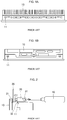
- FIGS. 1A and 1B are views showing upper and lower ends of an existing electronic device, respectively, where slots are formed.
- FIG. 2 is a view showing the existing electronic device mounted on the enclosure.
- slots 11 are formed at the corners of each of the upper and lower ends of the electronic device 10.
- brackets 30 are disposed at the upper and lower ends of the electronic device 10.
- the hook 32 is inserted into one of the slots 11 formed at the corners of the upper and lower ends of the electronic device 10 and serves to fix the bracket 30 at that position.
- each of the brackets 30 are disposed along the periphery of the rear part of the electronic device 10 as shown in FIG. 2 .
- the electronic device 10 is located in an opening 21 formed in the enclosure 20 such that its front part protrudes from the front face of the enclosure 20 and its rear part protrudes from the rear face of the enclosure 20.
- a screw bolt 31 is screwed into the bracket 30. Both ends of the screw bolt 31 are exposed from both ends of the bracket 30, respectively.
- the other end of the screw bolt 31 gradually advances so that it may be brought into tight contact with the rear face of the enclosure 20.
- the both parts of the electronic device 10 can be fixed together with the enclosure 20 therebetween.
- the bracket 30 is formed by plating, and thus it may be bent when a torque greater than a certain level is applied. Therefore, there is a problem that the bracket cannot fix electronic devices.
- Korean Utility Model Publication No. 20-1994-0014102 discloses a combinating device for front cabinet of electronic device.
- a bracket for fixing an electronic device there is provided a bracket for fixing an electronic device.
- the bracket fixes an electronic device that is accommodated in an opening formed in an enclosure and has a front cover in tight contact with the front face of the enclosure in the vicinity of the opening.
- the bracket includes a bracket body that has a first end supporting a rear part of the electronic device and a second end in contact with a periphery of the rear part of the electronic device; and a coupling member disposed in the bracket body to press the front cover and the second end of the bracket body against each other from the front and rear faces of the enclosure, to fix the electronic device.
- the bracket body may have a first portion having a fasting hole through which the coupling member passes, and a second portion bent from the first portion to surround the periphery of the rear part of the electronic device.
- the coupling member may be coupled with the periphery of the rear part of the electronic device by being screwed, and an end of the second portion may form a supporting region in tight contact with the rear face of the enclosure near the opening
- a guide hole may be formed in the periphery of the rear part of the electronic device.
- a guide rod may protrude from the first portion, such that it is inserted into the guide hole to guide movement.
- the guide hole may be formed in a shape conforming to the guide rod.
- the longitudinal section of the guide rod may be formed in a polygonal shape.
- a guide groove for guiding the movement of the second portion may be further formed on the periphery of the rear part of the electronic device.
- An elastic member may be interposed between the front cover and the enclosure.
- an electronic device can be fixed to an enclosure by forming stable fixing force.
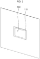
- FIG. 3 is a perspective view showing a front face of an electronic device installed in an enclosure by brackets for fixing an electronic device according to an exemplary embodiment of the present disclosure.
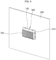
- FIG. 4 is a perspective view showing a rear face of an electronic device installed in an enclosure by brackets for fixing an electronic device according to an exemplary embodiment of the present disclosure.
- a bracket 300 for fixing an electronic device fixes an electronic device 100 that is disposed in an opening 210 formed in an enclosure 200 and has a front cover 110 formed along the periphery in contact with the vicinity of the opening 210 at the front face of the enclosure 200.
- the electronic device 100 may include an HMI device, a panel PC, etc.
- the front cover 110 is formed along the periphery of the front part of the electronic device 100 and is expanded outwardly.
- the electronic device 100 is fitted into the opening 210 formed in the enclosure 200.
- the front cover 110 is exposed from the front face of the enclosure 200 and is in contact with the vicinity of the opening 210.
- an elastic layer (not shown) may be further formed on an inner side surface of the front cover 210 so that the front cover 210 can be in tight contact with the enclosure 200 with elasticity.
- the rear part of the electronic device 100 is disposed to protrude from the rear face of the enclosure 200 through the opening 210 as shown in FIG. 4 .
- a plurality of brackets 300 according to the exemplary embodiment of the present disclosure is disposed such that the periphery of the rear part of the electronic device 100 are in tight contact with the vicinity of the opening 210 at the rear face of the enclosure 200.
- a supporting region is formed, which is brought into tight contact with the end of the second portion 312 and pressed.
- the electronic device 100 may be installed in tight contact with the enclosure 200 by pressing the front cover 110 disposed at the front face of the enclosure 200 and the brackets 130 disposed at the rear face of the enclosure 200 against each other when the electronic device 100 is located in the opening 210.
- FIG. 5 is a perspective view showing a configuration of a bracket for fixing an electronic device according to an exemplary embodiment of the present disclosure.
- FIG. 6 is a perspective view showing the rear part 101 of the electronic device where the brackets are disposed.
- the bracket 300 may include a bracket body 310 having a first portion 311 and a second portion 312, and a coupling member 320.
- the first portion 311 is disposed in tight contact with the rear part 101 of the electronic device 100.
- the second portion 312 is bent from the end of the first portion 311 and disposed to be in tight contact with the side surface of the periphery 120 of the rear part of the electronic device 100.
- the angle between the first and second portions 311 and 312 may be equal to the angle between the rear face and the top face of the periphery 120 of the rear part of the electronic device 100.
- an end of the second portion 312 is in contact with the rear face of the enclosure 200.
- a through hole 311a is formed in the first portion 311, via which the coupling member 320 passes.
- the coupling member 320 is a screw bolt.
- Fastening holes 121 are formed along the periphery of the rear part of the electronic device 100 such that they are spaced apart from one another.
- the fastening hole 121 is aligned with the through-hole 311a, so that the coupling member 320 may be inserted through the through hole 311a and the fastening hole 121.
- the first portion 311 can be fixed to the periphery 120 of the rear part of the electronic device 100.
- the first and second portions 311 and 312 may move forward and backward depending on the degree at which the coupling member 320 is fastened.
- the coupling member 320 when the coupling member 320 is rotated in the direction that it is fastened as being inserted into the through hole 311 a, the second portion 312 moves toward the rear face of the enclosure 200.
- a guide rod 330 is formed at the first portion 311, which has a predetermined length and protrudes from it.
- a guide hole 122 may be formed in the periphery 120 of the rear part of the electronic device 100.
- the shape of the guide rod 330 may be a circular bar, and the shape of the guide hole 122 may be a cylindrical hole.
- the first portion 311 moves back and forth as the guide rod 330 is inserted into the guide hole 122, and thus the movement is guided so that it is possible to prevent the first portion 311 from deviating.
- the guide hole 122 having the shape conforming to the cross section of the guide rod 330.
- FIG. 7 is a view showing the electronic device fixed to the enclosure by using the bracket according to the exemplary embodiment of the present disclosure.
- FIG. 8 is a view showing the elastic member interposed between the front cover and the enclosure according to the exemplary embodiment of the present disclosure.
- FIG. 9 is a cross-sectional view showing the bracket when it is installed.
- the electronic device 100 may be located in the opening 210 formed in the enclosure 200 as shown in FIGS. 3 and 4 .
- the front cover 110 is in contact with the front face of the enclosure 200, and the rear part of the electronic device 100 protrudes along the rear face of the enclosure 200.
- the plurality of brackets 300 according to the exemplary embodiment of the present disclosure is disposed.
- each of the brackets 300 is fastened by fastening the coupling member 320 inserted into the through hole 311a into the fastening hole 121 formed in the periphery of the rear part of the electronic device 100.
- the second portion 312 is located on the outer surface of the periphery 120 of the rear part of the electronic device 100.
- an end of the second portion 312 faces the rear face of the enclosure 200.
- the coupling member 320 is rotated to be gradually fastened into the fastening hole 121.
- the second portion 312 is moved close to the rear face of the enclosure 200 at the outer side surface of the periphery of the rear part 120 of the electronic device 200, thereby pressing the rear face of the enclosure 200.
- the front cover 110 and the end of the second portion 312 can be pressed against each other with the enclosure 200 therebetween, so that the electronic device 100 can be stably fixed in the opening 210.
- a guide rod 330 protruding from the first portion 311 is formed.
- the guide rod 330 is to be inserted into a guide hole 122 formed in the periphery of the rear part 120 of the electronic device 100 so as to be movable.
- an elastic member 340 is interposed between the front cover 110 and the enclosure 200. Accordingly, when the front cover 110 and the end of the second portion 312 are pressed against each other, with the enclosure 200 therebetween, an elastic force may be applied to increase the efficiency of the degree of contact and to absorb external impact.
- the elastic member 340 is interposed, it is possible to prevent foreign matter from being introduced into the opening 210 where the electronic device 100 is fixed.
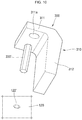
- FIG. 10 is a view showing another example of the guide member.
- the longitudinal section of the guide rod 330' may have a polygonal shape.
- the guide rod 330' may have a polygonal shape and may be formed as a rod having a certain length.
- a guide hole 122' formed in the periphery 120 of the rear part of the electronic device 100 may also be formed as a polygonal groove.
- the guide rod 330' formed in a polygonal shape may move back and forth as being inserted into the polygonal guide hole 122'.
- the guide rod 330' is not rotated in the process of bringing the second portion 312 into contact with the rear face of the enclosure 200, and thus it is possible to effectively prevent a problem that the second portion 312 deviates along the rotation direction.
- FIG. 11 is a view showing an example of a guide groove formed in an outer side surface of the periphery of the rear part of the electronic device.
- a guide groove 123 may be formed on the outer surface of the periphery of the rear part 120 of the electronic device 100.
- the width of the guide groove 123 may be substantially equal to the width of the second portion 312.
- the guide groove 123 may be formed along the moving direction of the second portion 312.
- the second portion 312 is moved along the guide groove 123 in the process of bringing the second portion 312 into contact with the enclosure 200, so that it is possible to prevent the deviation of the moving path.
- the bracket according to the exemplary embodiments of the present disclosure can form a stable fixing force, so that the electronic device can be fixed to the enclosure.
Landscapes
- Engineering & Computer Science (AREA)
- Microelectronics & Electronic Packaging (AREA)
- General Engineering & Computer Science (AREA)
- Computer Hardware Design (AREA)
- Theoretical Computer Science (AREA)
- Power Engineering (AREA)
- Physics & Mathematics (AREA)
- General Physics & Mathematics (AREA)
- Human Computer Interaction (AREA)
- Mechanical Engineering (AREA)
- Casings For Electric Apparatus (AREA)
- Mounting Components In General For Electric Apparatus (AREA)
- Patch Boards (AREA)
Applications Claiming Priority (1)
| Application Number | Priority Date | Filing Date | Title |
|---|---|---|---|
| KR1020170028245A KR102325744B1 (ko) | 2017-03-06 | 2017-03-06 | 전자기기 고정용 브라켓 및 전자기기 고정 구조 |
Publications (2)
| Publication Number | Publication Date |
|---|---|
| EP3373108A1 true EP3373108A1 (fr) | 2018-09-12 |
| EP3373108B1 EP3373108B1 (fr) | 2023-04-19 |
Family
ID=61526591
Family Applications (1)
| Application Number | Title | Priority Date | Filing Date |
|---|---|---|---|
| EP18159112.4A Active EP3373108B1 (fr) | 2017-03-06 | 2018-02-28 | Support pour fixer un dispositif électronique et mécanisme de fixation de dispositif électronique |
Country Status (5)
| Country | Link |
|---|---|
| US (1) | US20180255654A1 (fr) |
| EP (1) | EP3373108B1 (fr) |
| JP (1) | JP6816050B2 (fr) |
| KR (1) | KR102325744B1 (fr) |
| CN (1) | CN108541176B (fr) |
Families Citing this family (9)
| Publication number | Priority date | Publication date | Assignee | Title |
|---|---|---|---|---|
| KR101976432B1 (ko) * | 2018-02-21 | 2019-05-09 | 엘에스산전 주식회사 | 전자기기의 결합 장치 |
| US10772226B2 (en) * | 2018-03-27 | 2020-09-08 | Otis Elevator Company | Waterproof cover |
| WO2020110220A1 (fr) * | 2018-11-28 | 2020-06-04 | 理化工業株式会社 | Accessoire de fixation et unité de commande |
| KR20200098957A (ko) | 2019-02-13 | 2020-08-21 | 엘에스일렉트릭(주) | 전자기기 고정용 브래킷 |
| KR102873669B1 (ko) * | 2019-10-25 | 2025-10-21 | 엘지이노텍 주식회사 | 인쇄회로기판 모듈 및 이를 포함하는 컨버터 |
| JP7446849B2 (ja) * | 2020-02-18 | 2024-03-11 | シュナイダーエレクトリックホールディングス株式会社 | 取付具および装置取付構造 |
| JP7362511B2 (ja) * | 2020-02-27 | 2023-10-17 | シュナイダーエレクトリックホールディングス株式会社 | 取付具および装置取付構造 |
| KR200499214Y1 (ko) * | 2022-04-12 | 2025-06-04 | 주식회사 일룸 | 콘센트 어셈블리 |
| DE202024101415U1 (de) * | 2024-03-20 | 2025-06-23 | WAGO Verwaltungsgesellschaft mit beschränkter Haftung | Panelbefestigung in einem Ausschnitt |
Citations (3)
| Publication number | Priority date | Publication date | Assignee | Title |
|---|---|---|---|---|
| KR970004504Y1 (ko) | 1992-11-20 | 1997-05-12 | 배순훈 | 전자제품의 프론트캐비넷 결합장치 |
| DE212013000290U1 (de) * | 2013-03-28 | 2015-11-06 | Eizo Nanao Corporation | Bildanzeigevorrichtung zum Einbau in eine Konsole |
| US9494984B1 (en) * | 2015-06-30 | 2016-11-15 | Lite-On Electronics (Guangzhou) Limited | Fixing structure of removable electronic device |
Family Cites Families (22)
| Publication number | Priority date | Publication date | Assignee | Title |
|---|---|---|---|---|
| US670763A (en) * | 1900-11-30 | 1901-03-26 | Magloire Brodeur | Securer for machinery-legs. |
| US2055990A (en) * | 1935-01-31 | 1936-09-29 | Westinghouse Electric & Mfg Co | Instrument casing |
| US2917267A (en) * | 1956-12-07 | 1959-12-15 | Librascope Inc | Clamp |
| US3171623A (en) * | 1962-12-07 | 1965-03-02 | Gen Electric | Instrument panel mounting system |
| JPS546829Y2 (fr) * | 1972-03-18 | 1979-03-31 | ||
| JPS5238165A (en) * | 1975-09-20 | 1977-03-24 | Omron Tateisi Electronics Co | Mounting device for control apparatus |
| US4310133A (en) * | 1978-08-07 | 1982-01-12 | Dresser Industries, Inc. | Clamp for panel mounting of gauge instruments |
| JPS5926625Y2 (ja) * | 1980-02-08 | 1984-08-02 | 株式会社東芝 | 筐体 |
| US4410155A (en) * | 1980-04-14 | 1983-10-18 | Dresser Industries, Inc. | Clamp for panel mounting of gauge instruments |
| DE8619379U1 (de) * | 1986-07-18 | 1986-08-28 | Bündoplast bopla Gehäuse Systeme GmbH, 4980 Bünde | Gehäuse zum Einsetzen in Schalttafeln |
| JPH0467389A (ja) * | 1990-07-02 | 1992-03-03 | Mitsubishi Electric Corp | 半導体集積回路 |
| JPH0710549Y2 (ja) * | 1990-10-19 | 1995-03-08 | オムロン株式会社 | 電子機器の取り付け構造 |
| US5609414A (en) * | 1995-11-24 | 1997-03-11 | Canlyte Inc. | Recessed lighting fixture |
| JP2002252053A (ja) * | 2001-02-21 | 2002-09-06 | Molex Inc | コネクタの固定構造 |
| US20030209645A1 (en) * | 2002-05-08 | 2003-11-13 | Degrazia Dean Basil | Universal motor bracket for motor operators |
| US7172160B2 (en) * | 2004-10-28 | 2007-02-06 | Honeywell International, Inc. | Mechanical mounting configuration for flushmount devices |
| CN102118949A (zh) * | 2009-12-30 | 2011-07-06 | 鸿富锦精密工业(深圳)有限公司 | 固定机构及采用该固定机构的机箱 |
| CN201585222U (zh) * | 2010-01-15 | 2010-09-15 | 珠海格力电器股份有限公司 | 一种主板固定支架单元及由其组成的主板固定支架 |
| JP5761012B2 (ja) * | 2011-12-28 | 2015-08-12 | Tdk株式会社 | ブラケット及び電子機器 |
| JP5649638B2 (ja) * | 2012-12-10 | 2015-01-07 | 三菱電機株式会社 | 制御装置 |
| CN104181997A (zh) * | 2013-05-23 | 2014-12-03 | 鸿富锦精密工业(深圳)有限公司 | 电子装置壳体 |
| DE202016101176U1 (de) * | 2016-03-04 | 2016-06-03 | Omron Corporation | Gehäuse für einen Monitor eines Industriecomputers, Monitor für einen Industriecomputer und Industriecomputer |
-
2017
- 2017-03-06 KR KR1020170028245A patent/KR102325744B1/ko active Active
-
2018
- 2018-01-11 US US15/868,641 patent/US20180255654A1/en not_active Abandoned
- 2018-02-28 EP EP18159112.4A patent/EP3373108B1/fr active Active
- 2018-03-02 JP JP2018037831A patent/JP6816050B2/ja not_active Expired - Fee Related
- 2018-03-06 CN CN201810181676.3A patent/CN108541176B/zh active Active
Patent Citations (3)
| Publication number | Priority date | Publication date | Assignee | Title |
|---|---|---|---|---|
| KR970004504Y1 (ko) | 1992-11-20 | 1997-05-12 | 배순훈 | 전자제품의 프론트캐비넷 결합장치 |
| DE212013000290U1 (de) * | 2013-03-28 | 2015-11-06 | Eizo Nanao Corporation | Bildanzeigevorrichtung zum Einbau in eine Konsole |
| US9494984B1 (en) * | 2015-06-30 | 2016-11-15 | Lite-On Electronics (Guangzhou) Limited | Fixing structure of removable electronic device |
Also Published As
| Publication number | Publication date |
|---|---|
| CN108541176A (zh) | 2018-09-14 |
| EP3373108B1 (fr) | 2023-04-19 |
| JP2018148213A (ja) | 2018-09-20 |
| JP6816050B2 (ja) | 2021-01-20 |
| KR20180101821A (ko) | 2018-09-14 |
| CN108541176B (zh) | 2021-01-12 |
| KR102325744B1 (ko) | 2021-11-11 |
| US20180255654A1 (en) | 2018-09-06 |
Similar Documents
| Publication | Publication Date | Title |
|---|---|---|
| EP3373108B1 (fr) | Support pour fixer un dispositif électronique et mécanisme de fixation de dispositif électronique | |
| US10194556B2 (en) | Slide rail mechanism and bracket device thereof | |
| JP6324421B2 (ja) | ブラケットを備えたスライドレールアセンブリ | |
| US6377447B1 (en) | Quick release disk drive to chassis mounting apparatus and method | |
| TWI598024B (zh) | 滑軌總成及其托架 | |
| KR102041955B1 (ko) | 벽걸이 기기용 벽면 고정장치 | |
| US8520404B2 (en) | Fixing member for fixing blindfold plate and method of fixing blindfold plate | |
| US20180172927A1 (en) | Module structure | |
| US10533588B2 (en) | Fastener | |
| EP2497993A2 (fr) | Ensemble de structure d'armoire | |
| JP6305234B2 (ja) | 固定具 | |
| KR102363668B1 (ko) | 전자장치 및 계기 함체를 위한 장착 프레임 및 레일 | |
| JP5798080B2 (ja) | 配線器具取付体及び配線器具取付体の設置方法 | |
| US9146581B2 (en) | Hard disk drive mounting device and electronic device using the same | |
| JP6136067B2 (ja) | カウンターの固定構造 | |
| JP4940459B2 (ja) | ケーブル受金物の固定方法及び固定器具 | |
| US20210392763A1 (en) | Rear housing assembly and display device | |
| JP6712098B2 (ja) | かご室の鏡取付器具及び鏡取付方法 | |
| CN217892750U (zh) | 保险杠安装支架及车辆 | |
| KR200478619Y1 (ko) | 벽 장착 브라켓 | |
| JP6724064B2 (ja) | スライドレール機構及びスライドレールのための調節アセンブリ | |
| KR20190083735A (ko) | 선반 설치용 브라켓 및 이를 포함하는 선반 | |
| EP3453896B1 (fr) | Pièce de fixation | |
| KR20250155183A (ko) | 조립성 및 정밀도 향상을 위한 절곡기용 어댑터 | |
| JP4650501B2 (ja) | シールドフィンガーの取り付け装置 |
Legal Events
| Date | Code | Title | Description |
|---|---|---|---|
| PUAI | Public reference made under article 153(3) epc to a published international application that has entered the european phase |
Free format text: ORIGINAL CODE: 0009012 |
|
| STAA | Information on the status of an ep patent application or granted ep patent |
Free format text: STATUS: THE APPLICATION HAS BEEN PUBLISHED |
|
| AK | Designated contracting states |
Kind code of ref document: A1 Designated state(s): AL AT BE BG CH CY CZ DE DK EE ES FI FR GB GR HR HU IE IS IT LI LT LU LV MC MK MT NL NO PL PT RO RS SE SI SK SM TR |
|
| AX | Request for extension of the european patent |
Extension state: BA ME |
|
| STAA | Information on the status of an ep patent application or granted ep patent |
Free format text: STATUS: REQUEST FOR EXAMINATION WAS MADE |
|
| 17P | Request for examination filed |
Effective date: 20190311 |
|
| RBV | Designated contracting states (corrected) |
Designated state(s): AL AT BE BG CH CY CZ DE DK EE ES FI FR GB GR HR HU IE IS IT LI LT LU LV MC MK MT NL NO PL PT RO RS SE SI SK SM TR |
|
| STAA | Information on the status of an ep patent application or granted ep patent |
Free format text: STATUS: EXAMINATION IS IN PROGRESS |
|
| 17Q | First examination report despatched |
Effective date: 20190909 |
|
| GRAP | Despatch of communication of intention to grant a patent |
Free format text: ORIGINAL CODE: EPIDOSNIGR1 |
|
| STAA | Information on the status of an ep patent application or granted ep patent |
Free format text: STATUS: GRANT OF PATENT IS INTENDED |
|
| INTG | Intention to grant announced |
Effective date: 20230109 |
|
| RIC1 | Information provided on ipc code assigned before grant |
Ipc: H02B 1/044 20060101ALI20221219BHEP Ipc: H05K 7/14 20060101ALI20221219BHEP Ipc: H05K 5/00 20060101ALI20221219BHEP Ipc: G06F 1/18 20060101AFI20221219BHEP |
|
| GRAS | Grant fee paid |
Free format text: ORIGINAL CODE: EPIDOSNIGR3 |
|
| GRAA | (expected) grant |
Free format text: ORIGINAL CODE: 0009210 |
|
| STAA | Information on the status of an ep patent application or granted ep patent |
Free format text: STATUS: THE PATENT HAS BEEN GRANTED |
|
| AK | Designated contracting states |
Kind code of ref document: B1 Designated state(s): AL AT BE BG CH CY CZ DE DK EE ES FI FR GB GR HR HU IE IS IT LI LT LU LV MC MK MT NL NO PL PT RO RS SE SI SK SM TR |
|
| REG | Reference to a national code |
Ref country code: GB Ref legal event code: FG4D |
|
| REG | Reference to a national code |
Ref country code: CH Ref legal event code: EP |
|
| REG | Reference to a national code |
Ref country code: DE Ref legal event code: R096 Ref document number: 602018048487 Country of ref document: DE |
|
| REG | Reference to a national code |
Ref country code: IE Ref legal event code: FG4D |
|
| REG | Reference to a national code |
Ref country code: AT Ref legal event code: REF Ref document number: 1561681 Country of ref document: AT Kind code of ref document: T Effective date: 20230515 |
|
| REG | Reference to a national code |
Ref country code: LT Ref legal event code: MG9D |
|
| REG | Reference to a national code |
Ref country code: NL Ref legal event code: MP Effective date: 20230419 |
|
| REG | Reference to a national code |
Ref country code: AT Ref legal event code: MK05 Ref document number: 1561681 Country of ref document: AT Kind code of ref document: T Effective date: 20230419 |
|
| PG25 | Lapsed in a contracting state [announced via postgrant information from national office to epo] |
Ref country code: NL Free format text: LAPSE BECAUSE OF FAILURE TO SUBMIT A TRANSLATION OF THE DESCRIPTION OR TO PAY THE FEE WITHIN THE PRESCRIBED TIME-LIMIT Effective date: 20230419 |
|
| P01 | Opt-out of the competence of the unified patent court (upc) registered |
Effective date: 20230830 |
|
| PG25 | Lapsed in a contracting state [announced via postgrant information from national office to epo] |
Ref country code: SE Free format text: LAPSE BECAUSE OF FAILURE TO SUBMIT A TRANSLATION OF THE DESCRIPTION OR TO PAY THE FEE WITHIN THE PRESCRIBED TIME-LIMIT Effective date: 20230419 Ref country code: PT Free format text: LAPSE BECAUSE OF FAILURE TO SUBMIT A TRANSLATION OF THE DESCRIPTION OR TO PAY THE FEE WITHIN THE PRESCRIBED TIME-LIMIT Effective date: 20230821 Ref country code: NO Free format text: LAPSE BECAUSE OF FAILURE TO SUBMIT A TRANSLATION OF THE DESCRIPTION OR TO PAY THE FEE WITHIN THE PRESCRIBED TIME-LIMIT Effective date: 20230719 Ref country code: ES Free format text: LAPSE BECAUSE OF FAILURE TO SUBMIT A TRANSLATION OF THE DESCRIPTION OR TO PAY THE FEE WITHIN THE PRESCRIBED TIME-LIMIT Effective date: 20230419 Ref country code: AT Free format text: LAPSE BECAUSE OF FAILURE TO SUBMIT A TRANSLATION OF THE DESCRIPTION OR TO PAY THE FEE WITHIN THE PRESCRIBED TIME-LIMIT Effective date: 20230419 |
|
| PG25 | Lapsed in a contracting state [announced via postgrant information from national office to epo] |
Ref country code: RS Free format text: LAPSE BECAUSE OF FAILURE TO SUBMIT A TRANSLATION OF THE DESCRIPTION OR TO PAY THE FEE WITHIN THE PRESCRIBED TIME-LIMIT Effective date: 20230419 Ref country code: PL Free format text: LAPSE BECAUSE OF FAILURE TO SUBMIT A TRANSLATION OF THE DESCRIPTION OR TO PAY THE FEE WITHIN THE PRESCRIBED TIME-LIMIT Effective date: 20230419 Ref country code: LV Free format text: LAPSE BECAUSE OF FAILURE TO SUBMIT A TRANSLATION OF THE DESCRIPTION OR TO PAY THE FEE WITHIN THE PRESCRIBED TIME-LIMIT Effective date: 20230419 Ref country code: LT Free format text: LAPSE BECAUSE OF FAILURE TO SUBMIT A TRANSLATION OF THE DESCRIPTION OR TO PAY THE FEE WITHIN THE PRESCRIBED TIME-LIMIT Effective date: 20230419 Ref country code: IS Free format text: LAPSE BECAUSE OF FAILURE TO SUBMIT A TRANSLATION OF THE DESCRIPTION OR TO PAY THE FEE WITHIN THE PRESCRIBED TIME-LIMIT Effective date: 20230819 Ref country code: HR Free format text: LAPSE BECAUSE OF FAILURE TO SUBMIT A TRANSLATION OF THE DESCRIPTION OR TO PAY THE FEE WITHIN THE PRESCRIBED TIME-LIMIT Effective date: 20230419 Ref country code: GR Free format text: LAPSE BECAUSE OF FAILURE TO SUBMIT A TRANSLATION OF THE DESCRIPTION OR TO PAY THE FEE WITHIN THE PRESCRIBED TIME-LIMIT Effective date: 20230720 Ref country code: AL Free format text: LAPSE BECAUSE OF FAILURE TO SUBMIT A TRANSLATION OF THE DESCRIPTION OR TO PAY THE FEE WITHIN THE PRESCRIBED TIME-LIMIT Effective date: 20230419 |
|
| PG25 | Lapsed in a contracting state [announced via postgrant information from national office to epo] |
Ref country code: FI Free format text: LAPSE BECAUSE OF FAILURE TO SUBMIT A TRANSLATION OF THE DESCRIPTION OR TO PAY THE FEE WITHIN THE PRESCRIBED TIME-LIMIT Effective date: 20230419 |
|
| PG25 | Lapsed in a contracting state [announced via postgrant information from national office to epo] |
Ref country code: SK Free format text: LAPSE BECAUSE OF FAILURE TO SUBMIT A TRANSLATION OF THE DESCRIPTION OR TO PAY THE FEE WITHIN THE PRESCRIBED TIME-LIMIT Effective date: 20230419 |
|
| REG | Reference to a national code |
Ref country code: DE Ref legal event code: R097 Ref document number: 602018048487 Country of ref document: DE |
|
| PG25 | Lapsed in a contracting state [announced via postgrant information from national office to epo] |
Ref country code: SM Free format text: LAPSE BECAUSE OF FAILURE TO SUBMIT A TRANSLATION OF THE DESCRIPTION OR TO PAY THE FEE WITHIN THE PRESCRIBED TIME-LIMIT Effective date: 20230419 Ref country code: SK Free format text: LAPSE BECAUSE OF FAILURE TO SUBMIT A TRANSLATION OF THE DESCRIPTION OR TO PAY THE FEE WITHIN THE PRESCRIBED TIME-LIMIT Effective date: 20230419 Ref country code: RO Free format text: LAPSE BECAUSE OF FAILURE TO SUBMIT A TRANSLATION OF THE DESCRIPTION OR TO PAY THE FEE WITHIN THE PRESCRIBED TIME-LIMIT Effective date: 20230419 Ref country code: EE Free format text: LAPSE BECAUSE OF FAILURE TO SUBMIT A TRANSLATION OF THE DESCRIPTION OR TO PAY THE FEE WITHIN THE PRESCRIBED TIME-LIMIT Effective date: 20230419 Ref country code: DK Free format text: LAPSE BECAUSE OF FAILURE TO SUBMIT A TRANSLATION OF THE DESCRIPTION OR TO PAY THE FEE WITHIN THE PRESCRIBED TIME-LIMIT Effective date: 20230419 Ref country code: CZ Free format text: LAPSE BECAUSE OF FAILURE TO SUBMIT A TRANSLATION OF THE DESCRIPTION OR TO PAY THE FEE WITHIN THE PRESCRIBED TIME-LIMIT Effective date: 20230419 |
|
| PLBE | No opposition filed within time limit |
Free format text: ORIGINAL CODE: 0009261 |
|
| STAA | Information on the status of an ep patent application or granted ep patent |
Free format text: STATUS: NO OPPOSITION FILED WITHIN TIME LIMIT |
|
| 26N | No opposition filed |
Effective date: 20240122 |
|
| PG25 | Lapsed in a contracting state [announced via postgrant information from national office to epo] |
Ref country code: SI Free format text: LAPSE BECAUSE OF FAILURE TO SUBMIT A TRANSLATION OF THE DESCRIPTION OR TO PAY THE FEE WITHIN THE PRESCRIBED TIME-LIMIT Effective date: 20230419 |
|
| PG25 | Lapsed in a contracting state [announced via postgrant information from national office to epo] |
Ref country code: SI Free format text: LAPSE BECAUSE OF FAILURE TO SUBMIT A TRANSLATION OF THE DESCRIPTION OR TO PAY THE FEE WITHIN THE PRESCRIBED TIME-LIMIT Effective date: 20230419 Ref country code: IT Free format text: LAPSE BECAUSE OF FAILURE TO SUBMIT A TRANSLATION OF THE DESCRIPTION OR TO PAY THE FEE WITHIN THE PRESCRIBED TIME-LIMIT Effective date: 20230419 |
|
| PG25 | Lapsed in a contracting state [announced via postgrant information from national office to epo] |
Ref country code: MC Free format text: LAPSE BECAUSE OF FAILURE TO SUBMIT A TRANSLATION OF THE DESCRIPTION OR TO PAY THE FEE WITHIN THE PRESCRIBED TIME-LIMIT Effective date: 20230419 |
|
| REG | Reference to a national code |
Ref country code: CH Ref legal event code: PL |
|
| PG25 | Lapsed in a contracting state [announced via postgrant information from national office to epo] |
Ref country code: LU Free format text: LAPSE BECAUSE OF NON-PAYMENT OF DUE FEES Effective date: 20240228 |
|
| PG25 | Lapsed in a contracting state [announced via postgrant information from national office to epo] |
Ref country code: CH Free format text: LAPSE BECAUSE OF NON-PAYMENT OF DUE FEES Effective date: 20240229 |
|
| GBPC | Gb: european patent ceased through non-payment of renewal fee |
Effective date: 20240228 |
|
| PG25 | Lapsed in a contracting state [announced via postgrant information from national office to epo] |
Ref country code: LU Free format text: LAPSE BECAUSE OF NON-PAYMENT OF DUE FEES Effective date: 20240228 Ref country code: CH Free format text: LAPSE BECAUSE OF NON-PAYMENT OF DUE FEES Effective date: 20240229 |
|
| PG25 | Lapsed in a contracting state [announced via postgrant information from national office to epo] |
Ref country code: BG Free format text: LAPSE BECAUSE OF FAILURE TO SUBMIT A TRANSLATION OF THE DESCRIPTION OR TO PAY THE FEE WITHIN THE PRESCRIBED TIME-LIMIT Effective date: 20230419 |
|
| PG25 | Lapsed in a contracting state [announced via postgrant information from national office to epo] |
Ref country code: BG Free format text: LAPSE BECAUSE OF FAILURE TO SUBMIT A TRANSLATION OF THE DESCRIPTION OR TO PAY THE FEE WITHIN THE PRESCRIBED TIME-LIMIT Effective date: 20230419 |
|
| REG | Reference to a national code |
Ref country code: BE Ref legal event code: MM Effective date: 20240229 |
|
| PG25 | Lapsed in a contracting state [announced via postgrant information from national office to epo] |
Ref country code: BE Free format text: LAPSE BECAUSE OF NON-PAYMENT OF DUE FEES Effective date: 20240229 |
|
| PG25 | Lapsed in a contracting state [announced via postgrant information from national office to epo] |
Ref country code: GB Free format text: LAPSE BECAUSE OF NON-PAYMENT OF DUE FEES Effective date: 20240228 |
|
| PG25 | Lapsed in a contracting state [announced via postgrant information from national office to epo] |
Ref country code: FR Free format text: LAPSE BECAUSE OF NON-PAYMENT OF DUE FEES Effective date: 20240229 |
|
| PG25 | Lapsed in a contracting state [announced via postgrant information from national office to epo] |
Ref country code: IE Free format text: LAPSE BECAUSE OF NON-PAYMENT OF DUE FEES Effective date: 20240228 |
|
| PG25 | Lapsed in a contracting state [announced via postgrant information from national office to epo] |
Ref country code: IE Free format text: LAPSE BECAUSE OF NON-PAYMENT OF DUE FEES Effective date: 20240228 Ref country code: GB Free format text: LAPSE BECAUSE OF NON-PAYMENT OF DUE FEES Effective date: 20240228 Ref country code: FR Free format text: LAPSE BECAUSE OF NON-PAYMENT OF DUE FEES Effective date: 20240229 Ref country code: BE Free format text: LAPSE BECAUSE OF NON-PAYMENT OF DUE FEES Effective date: 20240229 |
|
| PG25 | Lapsed in a contracting state [announced via postgrant information from national office to epo] |
Ref country code: CY Free format text: LAPSE BECAUSE OF FAILURE TO SUBMIT A TRANSLATION OF THE DESCRIPTION OR TO PAY THE FEE WITHIN THE PRESCRIBED TIME-LIMIT; INVALID AB INITIO Effective date: 20180228 |
|
| PG25 | Lapsed in a contracting state [announced via postgrant information from national office to epo] |
Ref country code: HU Free format text: LAPSE BECAUSE OF FAILURE TO SUBMIT A TRANSLATION OF THE DESCRIPTION OR TO PAY THE FEE WITHIN THE PRESCRIBED TIME-LIMIT; INVALID AB INITIO Effective date: 20180228 |
|
| PG25 | Lapsed in a contracting state [announced via postgrant information from national office to epo] |
Ref country code: TR Free format text: LAPSE BECAUSE OF FAILURE TO SUBMIT A TRANSLATION OF THE DESCRIPTION OR TO PAY THE FEE WITHIN THE PRESCRIBED TIME-LIMIT Effective date: 20230419 |
|
| PGFP | Annual fee paid to national office [announced via postgrant information from national office to epo] |
Ref country code: DE Payment date: 20251208 Year of fee payment: 9 |