EP3373113B1 - Vorrichtung zur erzeugung von pseudokraftempfindung - Google Patents
Vorrichtung zur erzeugung von pseudokraftempfindung Download PDFInfo
- Publication number
- EP3373113B1 EP3373113B1 EP16881704.7A EP16881704A EP3373113B1 EP 3373113 B1 EP3373113 B1 EP 3373113B1 EP 16881704 A EP16881704 A EP 16881704A EP 3373113 B1 EP3373113 B1 EP 3373113B1
- Authority
- EP
- European Patent Office
- Prior art keywords
- force sense
- pseudo force
- vibrators
- generation apparatus
- straight
- Prior art date
- Legal status (The legal status is an assumption and is not a legal conclusion. Google has not performed a legal analysis and makes no representation as to the accuracy of the status listed.)
- Active
Links
Images


Classifications
-
- B—PERFORMING OPERATIONS; TRANSPORTING
- B06—GENERATING OR TRANSMITTING MECHANICAL VIBRATIONS IN GENERAL
- B06B—METHODS OR APPARATUS FOR GENERATING OR TRANSMITTING MECHANICAL VIBRATIONS OF INFRASONIC, SONIC, OR ULTRASONIC FREQUENCY, e.g. FOR PERFORMING MECHANICAL WORK IN GENERAL
- B06B1/00—Methods or apparatus for generating mechanical vibrations of infrasonic, sonic, or ultrasonic frequency
- B06B1/02—Methods or apparatus for generating mechanical vibrations of infrasonic, sonic, or ultrasonic frequency making use of electrical energy
- B06B1/04—Methods or apparatus for generating mechanical vibrations of infrasonic, sonic, or ultrasonic frequency making use of electrical energy operating with electromagnetism
-
- A—HUMAN NECESSITIES
- A63—SPORTS; GAMES; AMUSEMENTS
- A63F—CARD, BOARD, OR ROULETTE GAMES; INDOOR GAMES USING SMALL MOVING PLAYING BODIES; VIDEO GAMES; GAMES NOT OTHERWISE PROVIDED FOR
- A63F13/00—Video games, i.e. games using an electronically generated display having two or more dimensions
- A63F13/25—Output arrangements for video game devices
- A63F13/28—Output arrangements for video game devices responding to control signals received from the game device for affecting ambient conditions, e.g. for vibrating players' seats, activating scent dispensers or affecting temperature or light
- A63F13/285—Generating tactile feedback signals via the game input device, e.g. force feedback
-
- G—PHYSICS
- G06—COMPUTING OR CALCULATING; COUNTING
- G06F—ELECTRIC DIGITAL DATA PROCESSING
- G06F3/00—Input arrangements for transferring data to be processed into a form capable of being handled by the computer; Output arrangements for transferring data from processing unit to output unit, e.g. interface arrangements
- G06F3/01—Input arrangements or combined input and output arrangements for interaction between user and computer
- G06F3/016—Input arrangements with force or tactile feedback as computer generated output to the user
-
- H—ELECTRICITY
- H04—ELECTRIC COMMUNICATION TECHNIQUE
- H04M—TELEPHONIC COMMUNICATION
- H04M19/00—Current supply arrangements for telephone systems
- H04M19/02—Current supply arrangements for telephone systems providing ringing current or supervisory tones, e.g. dialling tone or busy tone
- H04M19/04—Current supply arrangements for telephone systems providing ringing current or supervisory tones, e.g. dialling tone or busy tone the ringing-current being generated at the substations
- H04M19/047—Vibrating means for incoming calls
Definitions
- the present invention relates to a technology for making a user perceive pseudo force sense.
- Pseudo force sense generation apparatuses that make a user perceive pseudo force sense via asymmetrical motions of vibrators are known (see Non-patent Literature 1, for instance).
- Non-patent Literature 1 For improved usability and availability of a pseudo force sense generation apparatus, it is desirable that the entire apparatus, including vibrators and electronic circuitry for controlling them and the like, is mechanically integrated.
- a grip portion of a pseudo force sense generation apparatus to be gripped by the user is vibrated with a desired pattern and amplitude.
- the vibrators of the pseudo force sense generation apparatus are fixed with rigid members, however, the entire apparatus has to be moved for vibrating the grip portion with the desired pattern and amplitude, which is not efficient.
- Patent Literature 2 discloses a pseudo force sensation generating device having a base and first through n-th acceleration generators fixed on the base.
- An i-th acceleration generator of the first through n-th acceleration generators is capable of producing pseudo force sensation in an i-th linear direction, where n represents an integer 3 or greater, and i represents an integer 1 through n.
- An i-th linear direction is a linear direction along an i-th side among mutually different first through n-th sides of a virtual polygon having no less than n sides, including first through n-th sides, on a single plane.
- Patent Literature 3 discloses a cellular phone including acceleration generation units that generate asymmetric acceleration in two directions, thereby generating the sense of force in at least one of the two directions, and a cellular phone body in which the acceleration generation units are installed.
- the acceleration generation units are installed on the cellular phone body along axes that intersect each other.
- Non-patent Literature 1 Tomohiro Amemiya, Shinya Takamuku, Sho Ito, Hiroaki Gomi, "Buru-Navi3 Gives You a Feeling of Being Pulled", 2014, NTT Technical Review, Vol. 26, No. 9, pp. 23-26 .
- Patent Literature 1 however cannot vibrate the vibrators sufficiently independently from the electronic device unit and has difficulty in efficiently presenting a desired pseudo force sense.
- An object of the present invention is to efficiently present a desired pseudo force sense even when the relative positions of the vibrators to the electronic device unit are fixed.
- the present invention provides a pseudo force sense generation apparatus having the features of claim 1. Preferred embodiments are described in the dependent claims.
- An example that is useful for understanding the invention relates to a pseudo force sense generation apparatus including a base, and first to nth vibrators that make asymmetrical motions where relative positions of the vibrators to the base are fixed.
- An ith vibrator included in the first to the nth vibrators is each capable of presenting pseudo force sense in an ith straight-line direction.
- the pseudo force sense generation apparatus makes a rotary motion centered at a neighborhood of a center of gravity of a system by driving of the vibrators.
- the pseudo force sense generation apparatus enables efficient presentation of a desired pseudo force sense even when the relative positions of the vibrators to the electronic device unit are fixed.
- a pseudo force sense generation apparatus has a “base” and first to nth “vibrators” that make asymmetrical motions where relative positions of the vibrators to the "base” are fixed.
- the ith “vibrator” included in the first to the nth “vibrators” is each capable of presenting pseudo force sense in the ith straight-line direction.
- the pseudo force sense generation apparatus makes a rotary motion centered at a neighborhood of the center of gravity of a "system” by driving of the "vibrators".
- a system that makes a rotary motion centered at a neighborhood of the center of gravity has a small inertia moment (rotation moment).
- pseudo force sense can be efficiently presented even when the relative positions of the "vibrators" to a certain “electronic device unit” are fixed and the entire system including the "base” and the “vibrators” is moved.
- the ith straight-line direction is each a straight-line direction along one of the sides of a "virtual polygon" having three or more sides on the same plane, for example.
- the n 1 th straight-line direction (where n 1 ⁇ ⁇ 1, ..., n ⁇ ) included in the first to the nth straight-line directions is different from the n 2 th straight-line direction included in the first to the nth straight-line directions (where n 2 ⁇ ⁇ 1, ..., n ⁇ and n 2 ⁇ n 1 ).
- the n 1 th straight-line direction is a straight-line direction along the n 1 th side of the "virtual polygon”
- the n 2 th straight-line direction is a straight-line direction along the n 2 th side (a side different from the n 1 th side) of the "virtual polygon”.
- the "ith straight-line direction” is a straight-line direction along the ith side among the first to the nth sides that are included in the "virtual polygon” having n or more and three or more sides on the same plane and that are different from each other.
- two or more straight-line directions included in the first to the nth straight-line directions may be directions along the same side of the "virtual polygon".
- a rotary motion caused by driving of the first to the nth "vibrators” is vibration having a rotational component, for example, and can present pseudo rotational force sense of one-degree-of-freedom.
- a "rotational force sense” means force sense that is perceived as if an object is rotating (that is, pseudo force sense in a rotational direction); for example, it creates pseudo perception of torsion.
- the ith straight-line direction is a straight-line direction along the ith side among the first to the nth sides that are included in a "virtual polygon” having n or more and three or more sides on the same plane and that are different from each other
- each vertex of the "virtual polygon” will be referred to as “the first vertex”, “the second vertex”, ..., “the mth vertex” in the order along either one rotational direction.
- ⁇ mod ⁇ represents the remainder (residue) of ⁇ divided by ⁇ .
- At least the kth “vibrator” is capable of presenting pseudo force sense in a direction having a component from the ⁇ ((k-1) mod m) +1 ⁇ th vertex toward the ⁇ (k mod m) +1 ⁇ th vertex
- the pth "vibrator” is capable of presenting pseudo force sense in a direction having a component from the ⁇ ((p-1) mod m) +1 ⁇ th vertex toward the ⁇ (p mod m) +1 ⁇ th vertex (where k ⁇ p and k, p ⁇ ⁇ 1, ..., n ⁇ ).
- the "straight-line direction along side ⁇ " means any direction on a straight line along the side ⁇ .
- Examples of a “straight line along side ⁇ ” include a straight line passing through the side ⁇ , a straight line running alongside the side ⁇ , and a straight line parallel or substantially parallel with the side ⁇ .
- a “straight line along side ⁇ " may or may not pass through the side ⁇ .
- any ith side may not pass through the ith “vibrator” as long as each ith straight-line direction is a straight-line direction along the ith side.
- the "virtual polygon” described above is a convex polygon, for example. Examples of the “virtual polygon” include a triangle, a quadrangle, and a pentagon.
- the “system” means a system that includes the first to the nth "vibrators”.
- Examples of the “system” include a system composed of the first to the nth “vibrators", a system composed of the “base” and the first to the nth “vibrators”, a system composed of the "base”, the first to the nth “vibrators”, and an “electronic device unit”, and a system composed of the "base”, the first to the nth “vibrators”, an “electronic device unit”, and other members.
- the “neighborhood of the center of gravity” may either be the center of gravity or a vicinity of the center of gravity.
- An example of the "neighborhood of the center of gravity” is a point that is in a region surrounded by the first to the nth "vibrators" and that is away from the center of gravity at a distance equal to or less than a predetermined value.
- the rotary motion centered at a neighborhood of the center of gravity of the "system” caused by driving of "vibrators” may be generated by driving of the first to the nth “vibrators” or by some “vibrators” included in the first to the nth “vibrators”.
- the weight distribution of the system is biased toward a "neighborhood of the center of gravity of the system”. This enables clear presentation of pseudo force sense even if the mass of the "system” is large. That "the weight distribution of the system is biased toward a neighborhood of the center of gravity of the system” means that the mass per unit volume, i.e., density, in a "neighborhood of the center of gravity” is greater than the density of the remaining portion. In other words, it means that the density of an area within a predetermined distance from the center of gravity is greater than the density of the other area.
- the "system” includes an “electronic device unit” having a fixed relative position to the "base” and the “electronic device unit” is arranged in a “neighborhood of the center of gravity of the system” (the region of the “electronic device unit” contains the “neighborhood of the center of gravity of the system”).
- the “electronic device unit” may be arranged inside the “virtual polygon”.
- the “electronic device unit” includes at least some of a power supply unit (a battery), a power supply circuit, a control circuit for controlling the driving of the vibrators, and a display unit (a device for displaying visual information), for example.
- the power supply unit is particularly large in weight, the power supply unit is desirably arranged in a "neighborhood of the center of gravity of the system”.
- the pseudo force sense generation apparatus is configured such that the rotary motion energy of the pseudo force sense generation apparatus in presenting rotational force sense by driving of "vibrators” (the motion energy of the pseudo force sense generation apparatus while making a rotary motion) is smaller than the translational motion energy of the pseudo force sense generation apparatus in presenting translational force sense by driving of "vibrators” (the motion energy of the pseudo force sense generation apparatus while making a translational motion).
- driving power can be smaller when presenting rotational force sense than when presenting translational force sense.
- the "translational force sense” means force sense that is perceived as if an object is making a translational motion (that is, pseudo force sense in a straight-line direction).
- control is to be effected so that combination of the presentation directions of pseudo force sense presented by the first to the nth "vibrators" (a combined direction) will be a direction containing a straight line component along the plane (the same plane) on which the aforementioned "virtual polygon” is positioned.
- the “driving of vibrators” here may be driving of the first to the nth “vibrators” or driving of some “vibrators” included in the first to the nth “vibrators”.
- a “straight line component along a plane” means a directional component along any straight line on the "plane” (a straight line contained by the "plane”).
- a “directional component along a straight line” means a directional component of either direction on the "straight line”.
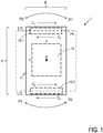
- a pseudo force sense generation apparatus 1 in this embodiment has a base 11, vibrators 12-1, 12-2 that make asymmetrical motions where relative positions of the vibrators to the base 11 are fixed, and an electronic device unit 14.
- the base 11 of this embodiment is, for example, a chassis or case having a tablet-shaped appearance and a hollow interior, in which the vibrators 12-1, 12-2 and the electronic device unit 14 are housed.
- the base 11 is desirably made of a rigid body; however, it does not have to be a rigid body in a strict sense but may be made of any material that can transfer the force generated in the vibrators 12-1, 12-2.
- the base 11 may be made of synthetic resin such as ABS resin, metal such as copper, glass, wood, rubber, or the like.
- the base 11 does not have to be made of a single material; a part of an electronic circuit board containing an insulative layer and a conductive layer may be used as the base 11, for example.
- a housing of an electronic device such as a mobile phone or a smartphone, or part of the housing may be used as the base 11.
- the vibrators 12-1, 12-2 in this embodiment are mechanically fixed inside the base 11.
- Each vibrator 12-i may be the actuator described in Non-patent Literature 1 or any other device that is capable of presenting pseudo translational force sense, for example.
- a first straight-line direction in this embodiment is straight-line directions C 1 , C 2 along one side L11 of a virtual quadrangle P1 (the virtual polygon), and a second straight-line direction is straight-line directions C 3 , C 4 along a side L12, which is opposite the side L11 of the virtual quadrangle P1.
- the straight-line directions C 1 , C 2 and the straight-line directions C 3 , C 4 are parallel with each other.
- the vibrator 12-1 is arranged on the side L11 and the vibrator 12-2 is arranged on the side L12.
- the virtual quadrangle P1 is positioned on a plane substantially parallel with a plate surface of the base 11 and has a fixed relative position to the base 11.
- the electronic device unit 14 is a device including at least some of a power supply unit, a power supply circuit, a control circuit for controlling the driving of the vibrators 12-1, 12-2, and a display unit, for example.
- the electronic device unit 14 is arranged between the vibrator 12-1 and the vibrator 12-2, and is mechanically fixed inside the base 11 (has a fixed relative position to the base). That is, the electronic device unit 14 is arranged inside the virtual quadrangle P1, and the center of gravity G or its vicinity of the system composed of the pseudo force sense generation apparatus 1 is positioned in the electronic device unit 14.
- the density of the electronic device unit 14 (the mass per unit volume) is greater than the densities of the other portions including the base 11 and the vibrators 12-1, 12-2. Accordingly, the weight distribution of the system of the pseudo force sense generation apparatus 1 is biased toward a neighborhood of the center of gravity G.
- the vibrator 12-1 makes periodical asymmetrical vibration that repeats a period during which it applies force in the straight-line direction C 1 and a period during which it applies force in the straight-line direction C 2 .
- the vibrator 12-2 makes periodical asymmetrical vibration that repeats a period during which it applies force in the straight-line direction C 3 and a period during which it applies force in the straight-line direction C 4 .
- Both of the vibrators 12-1, 12-2 apply large force for a short time in a direction in which pseudo force sense is to be presented and apply small force for a longer time in the opposite direction.
- the vibrator 12-1 is controlled so as to present pseudo force sense in the straight-line direction C 1
- the vibrator 12-2 is controlled so as to present pseudo force sense in the opposite direction, that is, the straight-line direction C 3 .
- the pseudo force sense generation apparatus 1 periodically repeats rotation in R1 direction and rotation in R2 direction, that is, the opposite direction (asymmetrical rotation), and the user gripping the pseudo force sense generation apparatus 1 perceives rotational force sense as if the pseudo force sense generation apparatus 1 is rotating in the R1 direction.
- the vibrator 12-1 is controlled so as to present pseudo force sense in the straight-line direction C 2
- the vibrator 12-2 is controlled so as to present pseudo force sense in the opposite direction, that is, the straight-line direction C 4 .
- the pseudo force sense generation apparatus 1 periodically repeats rotation in the R2 direction and rotation in the opposite R1 direction, and the user gripping the pseudo force sense generation apparatus 1 perceives rotational force sense as if the pseudo force sense generation apparatus 1 is rotating in the R2 direction.
- the center of such a rotary motion is at the center of gravity G or its vicinity. By positioning the center of a rotary motion at the center of gravity G or its vicinity, inertia moment around the rotation center can be minimized or reduced.
- a clear rotational force sense can be presented.
- the vibrator 12-1 is controlled so as to present pseudo force sense in the straight-line direction C 1
- the vibrator 12-2 is controlled so as to present pseudo force sense in the straight-line direction C 4
- the pseudo force sense generation apparatus 1 makes vibration that periodically repeats movement in the straight-line directions C 1 , C 4 and movement in the opposite straight-line directions C 2 , C 3
- the user gripping the pseudo force sense generation apparatus 1 perceives translational force sense as if the pseudo force sense generation apparatus 1 is moving in the straight-line directions C 1 , C 4 .
- the vibrator 12-1 is controlled so as to present pseudo force sense in the straight-line direction C 2 and the vibrator 12-2 is controlled so as to present pseudo force sense in the straight-line direction C 3 .
- the pseudo force sense generation apparatus 1 makes vibration that periodically repeats movement in the straight-line directions C 2 , C 3 and movement in the opposite straight-line directions C 1 , C 4 , and the user gripping the pseudo force sense generation apparatus 1 perceives translational force sense as if the pseudo force sense generation apparatus 1 is moving in the straight-line directions C 2 , C 3 .
- a clear translational force sense can be presented.
- the rotary motion energy of the pseudo force sense generation apparatus 1 in presenting rotational force sense by driving of the vibrators 12-1, 12-2 is smaller than the translational motion energy of the pseudo force sense generation apparatus 1 in presenting translational force sense by driving of the vibrators 12-1, 12-2.
- the power required for presenting rotational force sense is smaller than the power required for presenting translational force sense. That is, a configuration that biases the weight distribution of the system of the pseudo force sense generation apparatus 1 toward a neighborhood of the center of gravity G is suited for presenting rotational force sense via a rotary motion centered at a neighborhood of the center of gravity G, and can be driven with smaller power than when presenting translational force sense. This effect is assessed under the following preconditions:
- the power required for presentation of rotational force sense is about one tenth the power required for presentation of translational force sense.
- the electronic device unit 14 having a large mass is fixed at the center, the weight distribution of the system is biased toward a neighborhood of the center of gravity G, and the vibrators 12-1, 12-2 fixed outwardly of it are driven to make a rotary motion centered at a neighborhood of the center of gravity G of the system, thereby presenting rotational force sense.
- the weight distribution of the system of the pseudo force sense generation apparatus 1 toward a neighborhood of the center of gravity G, the inertia moment of a rotary motion centered at a neighborhood of the center of gravity G can be reduced.
- Asymmetrical rotation of the entire pseudo force sense generation apparatus 1 in an integrated manner can give stimulation not only to the fingertips of the user gripping the pseudo force sense generation apparatus 1 but to the palm and the like, creating perception of pseudo force sense with less sense of inconsistency.
- the electronic device unit 14 is arranged in a neighborhood of the rotation center of the pseudo force sense generation apparatus 1, vibration of the electronic device unit 14 can be reduced so that its reliability and useful life can be improved.
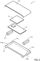
- a pseudo force sense generation apparatus 2 in this embodiment has the base 11, the electronic device unit 14, and the vibrators 12-1, 12-2.
- the base 11 has a box-shaped case portion 111 having an open side, and a lid portion 112 to cover the open side.
- the electronic device unit 14 has a circuit board 141 for controlling the vibrators 12-1, 12-2, and a power supply unit 142.
- the inner bottom surface of the case portion 111 is substantially rectangular, the vibrator 12-1 is fixed on the inner bottom surface on the side of one end 111a of the bottom surface in the longitudinal direction, and the vibrator 12-2 is fixed on the inner bottom surface on the side of another end 111b.
- the vibrator 12-1 presents translational force sense in a direction (C 1 or C 2 ) along a rim edge 111aa, which is on the one end 111a side of the case portion 111, via an asymmetrical motion in the direction along the rim edge 111aa.
- the vibrator 12-2 presents translational force sense in a direction (C 3 or C 4 ) along a rim edge 111ba, which is on the other end 111b side of the case portion 111, via an asymmetrical motion in the direction along the rim edge 111ba. That is, the vibrator 12-1 is capable of presenting pseudo force sense in the straight-line direction along a side L21 of a virtual quadrangle P2 having a fixed relative position to the inner bottom surface of the case portion 111. The vibrator 12-2 is capable of presenting pseudo force sense in the straight-line direction along a side L22 of the virtual quadrangle P2 having a fixed relative position to the inner bottom surface of the case portion 111.
- the side L21 is opposite the side L22 and they are parallel.
- the circuit board 141 and the power supply unit 142 are fixed.
- the center of gravity G or its vicinity of the system of the pseudo force sense generation apparatus 2 is positioned in the power supply unit 142 thus arranged.
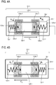
- the vibrator 12-1 has a supporting portion 121-1, springs 122-1, 123-1 (elastic bodies), a coil 124-1, a motion member 125-1, which is a permanent magnet, and a grip portion 126-1 (a case), for example.
- the grip portion 126-1 and the supporting portion 121-1 in this embodiment are both hollow members shaped in a tube (for example, a cylinder or a polyhedral tube) with its open ends on both sides closed.
- the supporting portion 121-1 is smaller than the grip portion 126-1 and is sized such that it can be housed in the grip portion 126-1.
- the grip portion 126-1 and the supporting portion 121-1 are made of synthetic resin such as ABS resin, for example.
- the springs 122-1, 123-1 are helical springs or leaf springs made of metal or the like, for example. Although the moduli of elasticity (spring constants) of the springs 122-1, 123-1 are desirably the same, they may be different from each other.
- the motion member 125-1 is a column-shaped permanent magnet, for example, where one end 125a-1 side in the longitudinal direction is the N-pole and another end 125b-1 side is the S-pole.
- the coil 124-1 is a string of enameled wire, for example, having a first wound portion 124a-1 and a second wound portion 124b-1.
- the motion member 125-1 is housed inside the supporting portion 121-1 and is supported therein so as to be slidable in the longitudinal direction. Although the details of such a supporting mechanism are not shown, a straight rail along the longitudinal direction is provided on an inner surface wall of the supporting portion 121-1 and a rail supporting portion that slidably supports the rail is provided on a side surface of the motion member 125-1, for example.
- One end of the spring 122-1 is fixed to an inner surface wall 121a-1 of the supporting portion 121-1 on one side in the longitudinal direction (that is, one end of the spring 122-1 is supported on the supporting portion 121-1), while the other end of the spring 122-1 is fixed to an end 125a-1 of the motion member 125-1 (that is, the end 125a-1 of the motion member 125-1 is supported on the other end of the spring 122-1).
- One end of the spring 123-1 is fixed to an inner wall surface 121b-1 of the supporting portion 121-1 on the other side in the longitudinal direction (that is, one end of the spring 123-1 is supported on the supporting portion 121-1), while the other end of the spring 123-1 is fixed to an end 125b-1 of the motion member 125-1 (that is, the end 125b-1 of the motion member 125-1 is supported on the other end of the spring 123-1).
- the coil 124-1 is wound on the outer periphery side of the supporting portion 121-1.
- the first wound portion 124a-1 is wound in A 1 direction (the direction from the back to the front), while on the end 125b-1 side (the S-pole side), the second wound portion 124b-1 is wound in B 1 direction, the opposite direction to A 1 direction (the direction from the front to the back). That is, when seen from the end 125a-1 side (the N-pole side) of the motion member 125-1, the first wound portion 124a-1 is wound clockwise and the second wound portion 124b-1 is wound counterclockwise.
- the end 125a-1 side (the N-pole side) of the motion member 125-1 is arranged in the region of the first wound portion 124a-1 and the end 125b-1 side (the S-pole side) is arranged in the region of the second wound portion 124b-1.
- the supporting portion 121-1, the springs 122-1, 123-1, the coil 124-1, and the motion member 125-1 arranged as described above are housed in the grip portion 126-1, and the supporting portion 121-1 is fixed inside the grip portion 126-1. That is, the relative position of the grip portion 126-1 to the supporting portion 121-1 is fixed.
- the longitudinal direction of the grip portion 126-1 coincides with the longitudinal direction of the supporting portion 121-1 and the longitudinal direction of the motion member 125-1.
- the coil 124-1 applies, to the motion member 125-1, force according to a current being passed in the coil 124-1, thereby causing the motion member 125-1 to make a periodical asymmetrical motion relative to the supporting portion 121-1 (a periodical translational reciprocating motion being asymmetrical in the axial direction with respect to the supporting portion 121-1). That is, when a current is passed through the coil 124-1 in A 1 direction (B 1 direction), force in C 1 direction (the direction from the N-pole to the S-pole of the motion member 125-1: the rightward direction) is applied to the motion member 125-1 ( Fig. 2A ) due to the reaction of Lorentz force explained by the Fleming's left hand rule.
- a first period during which current in a direction that gives the motion member 125-1 an acceleration in a desired direction (C 1 direction or C 2 direction) is passed through the coil 124-1 and the other, or a second, period are periodically repeated.
- the ratio (the inversion ratio) between the period (time) during which current is passed in a certain direction and the other period (time) is biased toward either one of the periods.
- a periodical current in which the proportion of the first period within a single cycle is different from the proportion of the second period within that cycle is passed through the coil 124-1. This enables presentation of pseudo force sense in a desired direction.
- FIGs. 5A to 5D this control will be described.
- the vertical axis represents the current value (current command value) [A] passed through the coil 124-1 and the horizontal axis represents time [msec].
- a current value in A 1 direction (B 1 direction) is represented by a positive value and a current value in A 2 direction (B 2 direction) is represented by a negative value.
- Figs. 5A to 5D the vertical axis represents the current value (current command value) [A] passed through the coil 124-1 and the horizontal axis represents time [msec].
- a current value in A 1 direction (B 1 direction) is represented by a positive value
- a current value in A 2 direction (B 2 direction) is represented by a negative value.
- 5A and 5B are examples that periodically repeat a period t 1 (the first period) during which current in A 1 direction (B 1 direction) (X: current in a direction that gives the motion member 125-1 an acceleration in C 1 direction) is passed and a period t 2 (the second period) during which current in A 2 direction (B 2 direction) (-X) is passed.
- a period t 1 the first period
- X current in a direction that gives the motion member 125-1 an acceleration in C 1 direction
- t 2 the second period
- the inversion ratio, t 1 :t 2 the inversion ratio
- a periodical current with an inversion ratio of t 1 >t 2 is passed through the coil 124-1 ( Fig. 5A ).
- a periodical current with an inversion ratio of t 1 ⁇ t 2 is passed through the coil 124-1 ( Fig. 5B ).
- Figs. 5C and 5D are examples that periodically repeat the period t 2 during which current in A 2 direction (B 2 direction) (-X) is passed and the period t 1 during which no current is passed, or periodically repeat the period (time) t 1 during which current in A 1 direction (B 1 direction) (X) is passed and the period t 2 during which no current is passed.
- the inversion ratio t 1 :t 2 between the period t 1 and the period t 2 is biased toward either one of the periods.
- a current that periodically repeats the period t 1 during which current in A 2 direction (B 2 direction) (-X: current in a direction that gives the motion member 125-1 an acceleration in C 2 direction) and the period t 2 during which no current is passed is passed through the coil 124-1.
- the inversion ratio t 1 :t 2 of this current is biased toward the period t 1 , being t 1 >t 2 ( Fig. 5C ).
- the inversion ratio t 1 :t 2 of this current is biased toward the period t 2 , being t 1 ⁇ t 2 ( Fig. 5D ).
- the current values (current command values) shown in Figs. 5A to 5D are rectangular waves.
- the current may have any waveform as long as the current periodically repeats a period during which current is passed in a certain direction and the other period, and the inversion ratio between the period during which current is passed in the certain direction and the other period is biased toward either one of the periods.
- control may be effected via voltage values instead of via current values.
- the vibrator 12-2 may have the same configuration as the vibrator 12-1.
- the user lightly grips the rim edge 111aa side of the pseudo force sense generation apparatus 2 with a left hand 102 and lightly grips the rim edge 111ba side with a right hand 101.
- the vibrator 12-1 is controlled so as to present pseudo force sense in the straight-line direction C 1
- the vibrator 12-2 is controlled so as to present pseudo force sense in the opposite direction, that is, the straight-line direction C 3 .
- the user gripping the pseudo force sense generation apparatus 2 perceives rotational force sense as if the pseudo force sense generation apparatus 2 is rotating in R1 direction.
- the vibrator 12-1 is controlled so as to present pseudo force sense in the straight-line direction C 2
- the vibrator 12-2 is controlled so as to present pseudo force sense in the opposite direction, that is, the straight-line direction C 4 .
- the user gripping the pseudo force sense generation apparatus 2 perceives rotational force sense as if the pseudo force sense generation apparatus 2 is rotating in R2 direction.
- the center of such a rotary motion is at the center of gravity G or its vicinity.
- the vibrator 12-1 is controlled so as to present pseudo force sense in the straight-line direction C 1 and the vibrator 12-2 is controlled so as to present pseudo force sense in the straight-line direction C 4 .
- the pseudo force sense generation apparatus 2 makes vibration that periodically repeats movement in straight-line directions C 1 , C 4 and movement in the opposite straight-line directions C 2 , C 3 , and the user gripping the pseudo force sense generation apparatus 2 perceives translational force sense as if the pseudo force sense generation apparatus 2 is moving in the straight-line directions C 1 , C 4 .
- the vibrator 12-1 is controlled so as to present pseudo force sense in the straight-line direction C 2 and the vibrator 12-2 is controlled so as to present pseudo force sense in the straight-line direction C 3 .
- the pseudo force sense generation apparatus 2 makes vibration that periodically repeats movement in the straight-line directions C 2 , C 3 and movement in the opposite straight-line directions C 1 , C 4 , and the user gripping the pseudo force sense generation apparatus 2 perceives translational force sense as if the pseudo force sense generation apparatus 2 is moving in the straight-line directions C 2 , C 3 .
- This embodiment also achieves the same effect as the first embodiment.
- a third embodiment will be described. This embodiment is a modification of the first embodiment.
- a pseudo force sense generation apparatus 3 in this embodiment has two grip portions 36, 37 each shaped in a cylinder or column with its both ends closed and having the same length, a cylindrical connector portion 35 (a base) mechanically coupling the central portions of the two grip portions 36, 37, an electronic device unit 34 fixed inside and at the center of the connector portion 35, and vibrators 31-1 to 31-4 respectively fixed at the opposite ends of the grip portions 36, 37.
- the grip portions 36, 37 are arranged substantially parallel (for example, parallel) with each other, and the connector portion 35 is arranged substantially vertically (for example, vertically) to the grip portions 36, 37.
- the vibrators 31-1, 31-4 are arranged at orientations that enable them to present pseudo force sense in straight-line directions C 311a , C 311b , C 314a , C 314b along the longitudinal direction of the grip portion 36, the vibrator 31-1 being fixed at one end of the grip portion 36 and the vibrator 31-4 being fixed at the other end of the grip portion 36.
- the vibrators 31-2, 31-3 are arranged at orientations that enable them to present pseudo force sense in straight-line directions C 312a , C 312b , C 313a , C 313b along the longitudinal direction of the grip portion 37, the vibrator 31-2 being fixed at one end of the grip portion 37 and the vibrator 31-3 being fixed at the other end of the grip portion 37.
- the vibrators 31-1, 31-2 are arranged on an upper surface side of the pseudo force sense generation apparatus 3 (on the side of Fig. 6A ), and the vibrators 31-3, 31-4 are arranged on a lower surface side of the pseudo force sense generation apparatus 3.
- the vibrators 31-1, 31-4 are thereby capable of presenting pseudo force sense in the straight-line directions C 311a , C 311b , C 314a , C 314b , which are along a side L31 of the virtual quadrangle P3 having a fixed relative position to the connector portion 35.
- the vibrators 31-2, 31-3 are capable of presenting pseudo force sense in the straight-line directions C 312a , C 312b , C 313a , C 313b , which are along a side L32 of the virtual quadrangle P3 having a fixed relative position to the connector portion 35.
- the side L31 and the side L32 are parallel with each other.
- the center of gravity G or its vicinity of the pseudo force sense generation apparatus 3 is positioned within the electronic device unit 34 (the electronic device unit 34 is positioned inside the virtual quadrangle P3), and the weight distribution of the pseudo force sense generation apparatus 3 is biased toward a neighborhood of the center of gravity G.
- the vibrators 31-1, 31-4 are controlled by the electronic device unit 34 so as to present pseudo force sense in straight-line directions C 311a , C 314a respectively, and the vibrators 31-2, 31-3 are controlled so as to present pseudo force sense in straight-line directions C 312a , C 313a respectively.
- the pseudo force sense generation apparatus 3 periodically repeats rotation in the S1 direction and rotation in the opposite S2 direction (asymmetrical rotation), and the user gripping the grip portions 36, 37 perceives rotational force sense as if the pseudo force sense generation apparatus 3 is rotating in the S1 direction.
- the vibrators 31-1, 31-4 are controlled so as to present pseudo force sense in straight-line directions C 311b , C 314b respectively, and the vibrators 31-2, 31-3 are controlled so as to present pseudo force sense in straight-line directions C 312b , C 313b respectively.
- the pseudo force sense generation apparatus 3 periodically repeats rotation in the S2 direction and rotation in the opposite S1 direction (asymmetrical rotation), and the user gripping the grip portions 36, 37 perceives rotational force sense as if the pseudo force sense generation apparatus 3 is rotating in the S2 direction.
- the center of such a rotary motion is at the center of gravity G or its vicinity.
- the vibrators 31-1, 31-2, 31-3, 31-4 are controlled so as to present pseudo force sense in straight-line directions C 311a , C 312b , C 314a , C 313b respectively.
- the pseudo force sense generation apparatus 3 makes vibration that periodically repeats movement in the straight-line directions C 311a , C 312b , C 314a , C 313b and movement in the opposite straight-line direction C 311b , C 312a , C 314b , C 313a , and the user gripping the pseudo force sense generation apparatus 3 perceives translational force sense as if the pseudo force sense generation apparatus 3 is moving in the straight-line directions C 311a , C 312b , C 314a , C 313b .
- the vibrators 31-1, 31-2, 31-3, 31-4 are controlled so as to present pseudo force sense in straight-line directions C 311b , C 312a , C 314b , C 313a respectively.
- the pseudo force sense generation apparatus 3 makes vibration that periodically repeats movement in the straight-line directions C 311b , C 312a , C 314b , C 313a and movement in the opposite straight-line directions C 311a , C 312b , C 314a , C 313b , and the user gripping the pseudo force sense generation apparatus 3 perceives translational force sense as if the pseudo force sense generation apparatus 3 is moving in the straight-line directions C 311b , C 312a , C 314b , C 313a .
- a fourth embodiment is a modification of the first embodiment and permits attachment and removal of the electronic device unit to/from the pseudo force sense generation apparatus.
- a pseudo force sense generation apparatus 4 in this embodiment has a base 41, and vibrators 12-1, 12-2 that make asymmetrical motions where relative positions of the vibrators 12-1, 12-2 to the base 41 are fixed.
- the base 41 of this embodiment is a case having a tablet-shaped appearance and a hollow interior, in which the vibrators 12-1, 12-2 are mechanically fixed.
- each vibrator 12-i is capable of presenting pseudo force sense (translational force sense) in the ith straight-line direction.
- a first straight-line direction in this embodiment is a straight-line direction along one side L41 of a virtual quadrangle P4, and a second straight-line direction is a straight-line direction along a side L42 opposite the side L41 of the virtual quadrangle P4.
- the virtual quadrangle P4 has a fixed relative position to the base 41.
- an electronic device unit 400 such as a smartphone can be attached.
- the center of gravity G of the system of the pseudo force sense generation apparatus 4 before attachment of the electronic device unit 400 is present in the region between the vibrator 12-1 and the vibrator 12-2.
- the center of gravity or its vicinity of the system composed of the electronic device unit 400 and the pseudo force sense generation apparatus 4 after attachment of the electronic device unit 400 is arranged in the electronic device unit 400.
- the weight distribution of the system composed of the electronic device unit 400 and the pseudo force sense generation apparatus 4 is biased toward a neighborhood of the center of gravity of the system.
- a rotary motion centered at a neighborhood of the center of gravity is generated, making the user gripping the external portions of the pseudo force sense generation apparatus 4 perceive rotational force sense.
- Such a pseudo force sense generation apparatus 4 is applicable to a smartphone case, for example.
- the user gripping the external portions of the pseudo force sense generation apparatus 4 may be made perceive translational force sense by controlling the vibrators 12-1, 2 as described in the first and second embodiments.
- a fifth embodiment is a modification of the fourth embodiment and differs from it in the number of vibrators.
- a pseudo force sense generation apparatus 5 in this embodiment has a base 51, and vibrators 52-1 to 52-4 that make asymmetrical motions where relative positions of the vibrators 52-1 to 52-4 to the base 51 are fixed.
- the base 51 in this embodiment is a case having a tablet-shaped appearance and a hollow interior, in which the vibrators 52-1 to 52-4 are mechanically fixed.
- each vibrator 52-i is capable of presenting pseudo force sense (translational force sense) in the ith straight-line direction.
- the configuration of each vibrator 52-i is the same as that of the vibrator 12-1 mentioned above, for example.
- a first straight-line direction in this embodiment is a straight-line direction along one side L51 of a virtual quadrangle P5
- a second straight-line direction is a straight-line direction along a side L52 perpendicular to the side L51 of the virtual quadrangle P5
- a third straight-line direction is a straight-line direction along a side L53 opposite the side L51 of the virtual quadrangle P5
- a fourth straight-line direction is a straight-line direction along a side L54 opposite the side L52 of the virtual quadrangle P5.
- the virtual quadrangle P5 has a fixed relative position to the base 51.
- the electronic device unit 400 such as a smartphone can be attached.
- the center of gravity G of the system of the pseudo force sense generation apparatus 5 before attachment of the electronic device unit 400 is present in the region surrounded by the vibrators 52-1 to 52-4.
- the center of gravity or its vicinity of the system composed of the electronic device unit 400 and the pseudo force sense generation apparatus 5 after attachment of the electronic device unit 400 is arranged in the electronic device unit 400.
- the weight distribution of the system composed of the electronic device unit 400 and the pseudo force sense generation apparatus 5 is biased toward a neighborhood of the center of gravity of the system.
- the vibrators 52-1, 52-2, 52-3, 52-4 are controlled by the electronic device unit 400 so as to present pseudo force sense in straight-line directions C 521a , C 522a , C 523a , C 524a respectively.
- the pseudo force sense generation apparatus 5 periodically repeats rotation in W1 direction and rotation in W2 direction, that is, the opposite direction (asymmetrical rotation), and the user gripping the external portions of the pseudo force sense generation apparatus 5 perceives rotational force sense as if the pseudo force sense generation apparatus 5 is rotating in the W1 direction.
- the vibrators 52-1, 52-2, 52-3, 52-4 are controlled so as to present pseudo force sense in straight-line directions C 521b , C 522b , C 523b , C 524b respectively.
- the pseudo force sense generation apparatus 5 periodically repeats rotation in the W2 direction and rotation in the opposite W1 direction (asymmetrical rotation), and the user gripping the external portions of the pseudo force sense generation apparatus 5 perceives rotational force sense as if the pseudo force sense generation apparatus 5 is rotating in the W2 direction.
- the center of such a rotary motion is at the center of gravity G or its vicinity. By positioning the center of a rotary motion at the center of gravity G or its vicinity, inertia moment around the rotation center can be minimized or reduced.
- this embodiment also enables perception of rotational force sense to be created through some of the vibrators 52-1 to 52-4 and perception of translational force sense to be created through other vibrators.
- one pair of opposite ones of the vibrators 52-1 to 52-4 may be controlled so as to create perception of rotational force sense and the other pair of vibrators may be controlled so as to create perception of translational force sense.
- vibrators 52-1, 52-3 are controlled so as to present pseudo force sense in straight-line directions C 521a , C 523a respectively
- vibrators 52-2, 52-4 are controlled so as to present pseudo force sense in straight-line directions C 522b , C 524a respectively.
- the pseudo force sense generation apparatus 5 periodically repeats rotation in the W1 direction and rotation in the opposite W2 direction (asymmetrical rotation), and also makes vibration that periodically repeats movement in the straight-line directions C 522b , C 524a and movement in the opposite straight-line directions C 522a , C 524b .
- the center of a rotary motion at the center of gravity G or its vicinity, inertia moment around the rotation center can be minimized or reduced, achieving the same effect as the first embodiment.
- a pseudo force sense generation apparatus 6 in this example has the base 41, vibrators 12-1, 12-2 that make asymmetrical motions where relative positions of the vibrators 12-1, 12-2 to the base 41 are fixed, an electronic device unit 62, and an electric cable 63.
- a difference from the fourth embodiment is that the electronic device unit is not attached inside the base 41 but the electronic device unit 62 is electrically connected to the base 41 via the electric cable 63.
- control of the vibrators 12-1, 12-2 is done by the electronic device unit 62.
- Control of the vibrators 12-1, 12-2 and the resulting presentation of rotational force sense are as described in the first and fourth embodiments.
- the center of gravity G of the system of the pseudo force sense generation apparatus 6 is positioned in a hollow region inside the base 41 between the vibrator 12-1 and the vibrator 12-2.
- the electronic device unit 62 is arranged outside the base 41.
- the base 41 and the vibrators 12-1, 12-2 are light in weight compared to the electronic device unit 62.
- clear pseudo force sense can be presented to the user gripping the external portions of the base 41.
- n vibrators may be any integer of two or more, whether an even number or an odd number.
- the embodiments showed examples where n vibrators are arranged on the same plane, the vibrators may not be arranged on the same plane.
- n vibrators may be arranged at positions on a surface of a virtual solid (for example, a sphere, a cube, a triangular prism, or a triangular pyramid) including a neighborhood of the center of gravity G.
- a virtual solid for example, a sphere, a cube, a triangular prism, or a triangular pyramid
- Each of the n vibrators vibrates in a direction along a straight line on the surface or in a direction along the tangent line to the surface to present translational force sense.
- the processing details are described by a program.
- functions of the above-described processing are implemented on the computer.
- the program describing the processing details can be recorded on a computer-readable recording medium.
- An example of the computer-readable recording medium is a non-transitory recording medium. Examples of such a recording medium include a magnetic recording device, an optical disk, a magneto-optical recording medium, and semiconductor memory.
- the distribution of this program is performed by, for example, selling, transferring, or lending a portable recording medium such as a DVD or a CD-ROM on which the program is recorded. Furthermore, a configuration may be adopted in which this program is distributed by storing the program in a storage device of a server computer and transferring the program to other computers from the server computer via a network.
- the computer that executes such a program first, for example, temporarily stores the program recorded on the portable recording medium or the program transferred from the server computer in a storage device thereof. At the time of execution of processing, the computer reads the program stored in the storage device thereof and executes the processing in accordance with the read program. As another mode of execution of this program, the computer may read the program directly from the portable recording medium and execute the processing in accordance with the program and, furthermore, every time the program is transferred to the computer from the server computer, the computer may sequentially execute the processing in accordance with the received program.
- a configuration may be adopted in which the transfer of a program to the computer from the server computer is not performed and the above-described processing is executed by so-called application service provider (ASP)-type service by which the processing functions are implemented only by an instruction for execution thereof and result acquisition.
- ASP application service provider
- Exemplary fields of industrial application of the present invention include a steering wheel controller for a driving game.
- Feedback of rotational force sense may be presented to the present apparatus representing a steering wheel in response to the action of a car during a game, enabling the user to experience feeling close to that felt during real driving.
- the present invention may be utilized for an apparatus that navigates the user to a desired destination through rotational force sense.
Landscapes
- Engineering & Computer Science (AREA)
- General Engineering & Computer Science (AREA)
- Multimedia (AREA)
- Theoretical Computer Science (AREA)
- Human Computer Interaction (AREA)
- Physics & Mathematics (AREA)
- Signal Processing (AREA)
- General Physics & Mathematics (AREA)
- Electromagnetism (AREA)
- Mechanical Engineering (AREA)
- User Interface Of Digital Computer (AREA)
- Apparatuses For Generation Of Mechanical Vibrations (AREA)
Claims (3)
- Pseudokraftmessungs-Erzeugungsvorrichtung (1, 2, 3, 4, 5), umfassend:eine Basis (11, 35, 41, 51);erste bis n-te Vibratoren (12-i, 31-i, 52-i), die asymmetrische Bewegungen ausführen, wobei relative Positionen der Vibratoren (12-i, 31-i, 52-i) zur Basis (11, 35, 41, 51) fest sind; undeine elektronische Vorrichtungseinheit (14) mit einer festen relativen Position zur Basis, wobeiein in den ersten bis n-ten Vibratoren enthaltener i-ter Vibrator (12-i, 31-i, 52-i) Pseudokraftmessungen in einer i-ten geradlinigen Richtungen präsentieren kann, wobei n eine Ganzzahl von 2 oder mehr ist und i = 1, ..., n,die i-te geradlinie Richtung eine geradlinige Richtung entlang einer der Seiten eines virtuellen Polygons (P1, P2, P3, P4, P5) mit drei oder mehr Seiten auf einer gleichen Ebene ist, unddie Pseudokraftmessungs-Erzeugungsvorrichtung (1, 2, 3, 4, 5) zum Ausführen einer Drehbewegung durch Antreiben der Vibratoren (12-i, 31-i, 52-i) ausgebildet ist, wobei die Drehbewegung in einem Schwerpunkt der Pseudokraftmessungs-Erzeugungsvorrichtung (1, 2, 3, 4, 5) oder dessen Nähe zentriert ist, so dass ein Trägheitsmoment um eine Drehmitte der Drehbewegung minimiert oder verringert wird,dadurch gekennzeichnet, dass:die elektronische Vorrichtungseinheit (14) innerhalb des virtuellen Polygons (P1, P2, P3, P4, P5) angeordnet ist,eine Masse pro Volumeneinheit der elektronischen Vorrichtungseinheit (14) größer ist als die Masse pro Volumeneinheit der Basis (11), undeine Gewichtsverteilung der Pseudokraftmessungs-Erzeugungsvorrichtung (1, 2, 3, 4, 5) zum Schwerpunkt hin verschoben ist.
- Pseudokraftmessungs-Erzeugungsvorrichtung (1, 2, 3, 4, 5) nach Anspruch 1, wobei eine Drehbewegungsenergie der Pseudokraftmessungs-Erzeugungsvorrichtung zum Präsentieren einer Drehkraftmessung durch Antreiben der Vibratoren kleiner ist als eine Translationsbewegungsenergie der Pseudokraftmessungs-Erzeugungsvorrichtung zum Präsentieren einer Translationskraftmessung durch Antreiben der Vibratoren.
- Pseudokraftmessungs-Erzeugungsvorrichtung (1, 2, 3, 4, 5) nach Anspruch 1 oder 2, wobei
die Basis eine drehsymmetrische Struktur aufweist, und
die Vibratoren in Drehsymmetrie zu einer Drehmitte der Drehbewegung angeordnet sind.
Applications Claiming Priority (2)
| Application Number | Priority Date | Filing Date | Title |
|---|---|---|---|
| JP2015256426 | 2015-12-28 | ||
| PCT/JP2016/088479 WO2017115729A1 (ja) | 2015-12-28 | 2016-12-22 | 擬似力覚発生装置 |
Publications (4)
| Publication Number | Publication Date |
|---|---|
| EP3373113A1 EP3373113A1 (de) | 2018-09-12 |
| EP3373113A4 EP3373113A4 (de) | 2019-04-17 |
| EP3373113B1 true EP3373113B1 (de) | 2020-11-04 |
| EP3373113B8 EP3373113B8 (de) | 2021-03-03 |
Family
ID=59225043
Family Applications (1)
| Application Number | Title | Priority Date | Filing Date |
|---|---|---|---|
| EP16881704.7A Active EP3373113B8 (de) | 2015-12-28 | 2016-12-22 | Vorrichtung zur erzeugung von pseudokraftempfindung |
Country Status (5)
| Country | Link |
|---|---|
| US (1) | US10864552B2 (de) |
| EP (1) | EP3373113B8 (de) |
| JP (1) | JP6594448B2 (de) |
| CN (1) | CN108431732B (de) |
| WO (1) | WO2017115729A1 (de) |
Families Citing this family (20)
| Publication number | Priority date | Publication date | Assignee | Title |
|---|---|---|---|---|
| JP7071614B2 (ja) * | 2017-01-27 | 2022-05-19 | ミツミ電機株式会社 | 振動装置、ウェアラブル端末及び着信通知機能デバイス |
| JP6873551B2 (ja) * | 2017-04-12 | 2021-05-19 | アルパイン株式会社 | 振動機構付き入力装置 |
| JP6884216B2 (ja) | 2017-08-24 | 2021-06-09 | 株式会社ソニー・インタラクティブエンタテインメント | 振動制御装置 |
| US11779836B2 (en) * | 2017-08-24 | 2023-10-10 | Sony Interactive Entertainment Inc. | Vibration control apparatus |
| GB201803084D0 (en) * | 2018-02-26 | 2018-04-11 | Cambridge Mechatronics Ltd | Haptic button with SMA |
| JP6891842B2 (ja) | 2018-03-26 | 2021-06-18 | 日本電信電話株式会社 | 触覚システム |
| JP6891843B2 (ja) | 2018-03-26 | 2021-06-18 | 日本電信電話株式会社 | 触覚装置 |
| CN108465237B (zh) * | 2018-03-27 | 2022-09-09 | 京东方科技集团股份有限公司 | 一种移动设备及其改变质心的方法 |
| JP2019185484A (ja) * | 2018-04-12 | 2019-10-24 | 日本電信電話株式会社 | 擬似力覚呈示装置 |
| US10691211B2 (en) | 2018-09-28 | 2020-06-23 | Apple Inc. | Button providing force sensing and/or haptic output |
| CN210155629U (zh) * | 2018-09-28 | 2020-03-17 | 苹果公司 | 提供力感测和触觉输出的模块 |
| US10599223B1 (en) * | 2018-09-28 | 2020-03-24 | Apple Inc. | Button providing force sensing and/or haptic output |
| JP7200790B2 (ja) | 2019-03-26 | 2023-01-10 | 日本電信電話株式会社 | 電子機器 |
| JP7120116B2 (ja) | 2019-03-28 | 2022-08-17 | 日本電信電話株式会社 | 触覚デバイス検査システム、装置、および方法 |
| JP7310887B2 (ja) | 2019-05-24 | 2023-07-19 | 日本電信電話株式会社 | 電子機器および制御方法 |
| US10976824B1 (en) * | 2019-09-26 | 2021-04-13 | Apple Inc. | Reluctance haptic engine for an electronic device |
| CN112580620A (zh) * | 2020-12-25 | 2021-03-30 | 北京百度网讯科技有限公司 | 标志图片处理方法、装置、设备和介质 |
| CN112717410B (zh) * | 2021-01-21 | 2023-03-14 | 腾讯科技(深圳)有限公司 | 虚拟对象控制方法、装置、计算机设备及存储介质 |
| JP7849823B2 (ja) * | 2023-09-06 | 2026-04-22 | 株式会社豊田中央研究所 | 触覚提示装置および触覚提示装置の制御方法 |
| CN117811414A (zh) * | 2023-12-06 | 2024-04-02 | 歌尔股份有限公司 | 一种振动装置的驱动电路及电子设备 |
Family Cites Families (10)
| Publication number | Priority date | Publication date | Assignee | Title |
|---|---|---|---|---|
| CN101173957B (zh) * | 2006-10-30 | 2011-12-21 | 索尼株式会社 | 角速度传感器及电子机器 |
| JP4692605B2 (ja) | 2008-10-27 | 2011-06-01 | ブラザー工業株式会社 | 携帯型装置 |
| JP2011183374A (ja) | 2010-02-10 | 2011-09-22 | Sanyo Electric Co Ltd | 電子機器 |
| CN103620928A (zh) * | 2011-03-17 | 2014-03-05 | 联合活跃驱动公司 | 多个同步振动致动器的非对称总体振动波形 |
| JP6277606B2 (ja) * | 2013-06-18 | 2018-02-14 | セイコーエプソン株式会社 | 振動素子、振動子、発振器、電子機器および移動体 |
| JP6264542B2 (ja) | 2014-01-30 | 2018-01-24 | 任天堂株式会社 | 情報処理装置、情報処理プログラム、情報処理システム、および情報処理方法 |
| JP6322830B2 (ja) * | 2014-05-09 | 2018-05-16 | 任天堂株式会社 | 情報処理装置、情報処理プログラム、情報処理システム、および情報処理方法 |
| JP6167068B2 (ja) | 2014-05-28 | 2017-07-19 | 日本電信電話株式会社 | 擬似力覚発生装置 |
| JP6148203B2 (ja) | 2014-05-28 | 2017-06-14 | 日本電信電話株式会社 | 擬似力覚発生装置 |
| JP6211991B2 (ja) * | 2014-05-28 | 2017-10-11 | 日本電信電話株式会社 | 加速度発生装置 |
-
2016
- 2016-12-22 US US16/063,543 patent/US10864552B2/en active Active
- 2016-12-22 EP EP16881704.7A patent/EP3373113B8/de active Active
- 2016-12-22 JP JP2017559169A patent/JP6594448B2/ja active Active
- 2016-12-22 CN CN201680076461.4A patent/CN108431732B/zh active Active
- 2016-12-22 WO PCT/JP2016/088479 patent/WO2017115729A1/ja not_active Ceased
Non-Patent Citations (1)
| Title |
|---|
| None * |
Also Published As
| Publication number | Publication date |
|---|---|
| CN108431732A (zh) | 2018-08-21 |
| US10864552B2 (en) | 2020-12-15 |
| JP6594448B2 (ja) | 2019-10-23 |
| WO2017115729A1 (ja) | 2017-07-06 |
| EP3373113A1 (de) | 2018-09-12 |
| EP3373113B8 (de) | 2021-03-03 |
| EP3373113A4 (de) | 2019-04-17 |
| JPWO2017115729A1 (ja) | 2018-09-27 |
| CN108431732B (zh) | 2021-03-26 |
| US20180369865A1 (en) | 2018-12-27 |
Similar Documents
| Publication | Publication Date | Title |
|---|---|---|
| EP3373113B1 (de) | Vorrichtung zur erzeugung von pseudokraftempfindung | |
| US20230050407A1 (en) | Pseudo force sense generation apparatus | |
| CN204810110U (zh) | 线性振动电机 | |
| TWI678057B (zh) | 振動產生裝置 | |
| JP2015225521A (ja) | 擬似力覚発生装置 | |
| WO2011099554A1 (ja) | 電子機器 | |
| US20250178030A1 (en) | Haptic device and haptic module | |
| CN106712436A (zh) | 一种线性振动马达 | |
| JP7797710B2 (ja) | 駆動励起器及び電子機器 | |
| JP6602650B2 (ja) | 擬似力覚発生装置 | |
| JP6148203B2 (ja) | 擬似力覚発生装置 | |
| JP7802210B2 (ja) | 駆動励起装置及び電子機器 | |
| JP2018149488A (ja) | 加振モジュールおよび触覚発生システム | |
| US20250337307A1 (en) | Drive Exciter and Electronic Device | |
| KR20160039175A (ko) | 휴대 단말의 진동 발생 방법 및 장치 | |
| JP7849823B2 (ja) | 触覚提示装置および触覚提示装置の制御方法 | |
| JP6293687B2 (ja) | 擬似力覚発生装置 |
Legal Events
| Date | Code | Title | Description |
|---|---|---|---|
| STAA | Information on the status of an ep patent application or granted ep patent |
Free format text: STATUS: THE INTERNATIONAL PUBLICATION HAS BEEN MADE |
|
| PUAI | Public reference made under article 153(3) epc to a published international application that has entered the european phase |
Free format text: ORIGINAL CODE: 0009012 |
|
| STAA | Information on the status of an ep patent application or granted ep patent |
Free format text: STATUS: REQUEST FOR EXAMINATION WAS MADE |
|
| 17P | Request for examination filed |
Effective date: 20180606 |
|
| AK | Designated contracting states |
Kind code of ref document: A1 Designated state(s): AL AT BE BG CH CY CZ DE DK EE ES FI FR GB GR HR HU IE IS IT LI LT LU LV MC MK MT NL NO PL PT RO RS SE SI SK SM TR |
|
| AX | Request for extension of the european patent |
Extension state: BA ME |
|
| DAV | Request for validation of the european patent (deleted) | ||
| DAX | Request for extension of the european patent (deleted) | ||
| A4 | Supplementary search report drawn up and despatched |
Effective date: 20190315 |
|
| RIC1 | Information provided on ipc code assigned before grant |
Ipc: G06F 3/01 20060101AFI20190308BHEP Ipc: A63F 13/285 20140101ALI20190308BHEP Ipc: B06B 1/04 20060101ALI20190308BHEP Ipc: H04M 19/04 20060101ALI20190308BHEP |
|
| STAA | Information on the status of an ep patent application or granted ep patent |
Free format text: STATUS: EXAMINATION IS IN PROGRESS |
|
| 17Q | First examination report despatched |
Effective date: 20191105 |
|
| GRAP | Despatch of communication of intention to grant a patent |
Free format text: ORIGINAL CODE: EPIDOSNIGR1 |
|
| STAA | Information on the status of an ep patent application or granted ep patent |
Free format text: STATUS: GRANT OF PATENT IS INTENDED |
|
| INTG | Intention to grant announced |
Effective date: 20200518 |
|
| GRAS | Grant fee paid |
Free format text: ORIGINAL CODE: EPIDOSNIGR3 |
|
| GRAA | (expected) grant |
Free format text: ORIGINAL CODE: 0009210 |
|
| STAA | Information on the status of an ep patent application or granted ep patent |
Free format text: STATUS: THE PATENT HAS BEEN GRANTED |
|
| AK | Designated contracting states |
Kind code of ref document: B1 Designated state(s): AL AT BE BG CH CY CZ DE DK EE ES FI FR GB GR HR HU IE IS IT LI LT LU LV MC MK MT NL NO PL PT RO RS SE SI SK SM TR |
|
| RAP1 | Party data changed (applicant data changed or rights of an application transferred) |
Owner name: NIPPON TELEGRAPH AND TELEPHONE COMPANY |
|
| REG | Reference to a national code |
Ref country code: GB Ref legal event code: FG4D |
|
| RIN1 | Information on inventor provided before grant (corrected) |
Inventor name: SHOJI, TETSUFUMI Inventor name: OCHIAI, KATSUYUKI Inventor name: GOMI, HIROAKI |
|
| REG | Reference to a national code |
Ref country code: CH Ref legal event code: EP |
|
| REG | Reference to a national code |
Ref country code: AT Ref legal event code: REF Ref document number: 1331645 Country of ref document: AT Kind code of ref document: T Effective date: 20201115 |
|
| REG | Reference to a national code |
Ref country code: IE Ref legal event code: FG4D |
|
| REG | Reference to a national code |
Ref country code: DE Ref legal event code: R096 Ref document number: 602016047472 Country of ref document: DE |
|
| RAP2 | Party data changed (patent owner data changed or rights of a patent transferred) |
Owner name: NIPPON TELEGRAPH AND TELEPHONE CORPORATION |
|
| REG | Reference to a national code |
Ref country code: CH Ref legal event code: PK Free format text: BERICHTIGUNG B8 |
|
| REG | Reference to a national code |
Ref country code: NL Ref legal event code: MP Effective date: 20201104 |
|
| REG | Reference to a national code |
Ref country code: AT Ref legal event code: MK05 Ref document number: 1331645 Country of ref document: AT Kind code of ref document: T Effective date: 20201104 |
|
| PG25 | Lapsed in a contracting state [announced via postgrant information from national office to epo] |
Ref country code: NO Free format text: LAPSE BECAUSE OF FAILURE TO SUBMIT A TRANSLATION OF THE DESCRIPTION OR TO PAY THE FEE WITHIN THE PRESCRIBED TIME-LIMIT Effective date: 20210204 Ref country code: PT Free format text: LAPSE BECAUSE OF FAILURE TO SUBMIT A TRANSLATION OF THE DESCRIPTION OR TO PAY THE FEE WITHIN THE PRESCRIBED TIME-LIMIT Effective date: 20210304 Ref country code: RS Free format text: LAPSE BECAUSE OF FAILURE TO SUBMIT A TRANSLATION OF THE DESCRIPTION OR TO PAY THE FEE WITHIN THE PRESCRIBED TIME-LIMIT Effective date: 20201104 Ref country code: FI Free format text: LAPSE BECAUSE OF FAILURE TO SUBMIT A TRANSLATION OF THE DESCRIPTION OR TO PAY THE FEE WITHIN THE PRESCRIBED TIME-LIMIT Effective date: 20201104 Ref country code: GR Free format text: LAPSE BECAUSE OF FAILURE TO SUBMIT A TRANSLATION OF THE DESCRIPTION OR TO PAY THE FEE WITHIN THE PRESCRIBED TIME-LIMIT Effective date: 20210205 |
|
| PG25 | Lapsed in a contracting state [announced via postgrant information from national office to epo] |
Ref country code: AT Free format text: LAPSE BECAUSE OF FAILURE TO SUBMIT A TRANSLATION OF THE DESCRIPTION OR TO PAY THE FEE WITHIN THE PRESCRIBED TIME-LIMIT Effective date: 20201104 Ref country code: ES Free format text: LAPSE BECAUSE OF FAILURE TO SUBMIT A TRANSLATION OF THE DESCRIPTION OR TO PAY THE FEE WITHIN THE PRESCRIBED TIME-LIMIT Effective date: 20201104 Ref country code: PL Free format text: LAPSE BECAUSE OF FAILURE TO SUBMIT A TRANSLATION OF THE DESCRIPTION OR TO PAY THE FEE WITHIN THE PRESCRIBED TIME-LIMIT Effective date: 20201104 Ref country code: LV Free format text: LAPSE BECAUSE OF FAILURE TO SUBMIT A TRANSLATION OF THE DESCRIPTION OR TO PAY THE FEE WITHIN THE PRESCRIBED TIME-LIMIT Effective date: 20201104 Ref country code: IS Free format text: LAPSE BECAUSE OF FAILURE TO SUBMIT A TRANSLATION OF THE DESCRIPTION OR TO PAY THE FEE WITHIN THE PRESCRIBED TIME-LIMIT Effective date: 20210304 Ref country code: BG Free format text: LAPSE BECAUSE OF FAILURE TO SUBMIT A TRANSLATION OF THE DESCRIPTION OR TO PAY THE FEE WITHIN THE PRESCRIBED TIME-LIMIT Effective date: 20210204 Ref country code: SE Free format text: LAPSE BECAUSE OF FAILURE TO SUBMIT A TRANSLATION OF THE DESCRIPTION OR TO PAY THE FEE WITHIN THE PRESCRIBED TIME-LIMIT Effective date: 20201104 |
|
| REG | Reference to a national code |
Ref country code: LT Ref legal event code: MG9D |
|
| PG25 | Lapsed in a contracting state [announced via postgrant information from national office to epo] |
Ref country code: HR Free format text: LAPSE BECAUSE OF FAILURE TO SUBMIT A TRANSLATION OF THE DESCRIPTION OR TO PAY THE FEE WITHIN THE PRESCRIBED TIME-LIMIT Effective date: 20201104 |
|
| REG | Reference to a national code |
Ref country code: DE Ref legal event code: R119 Ref document number: 602016047472 Country of ref document: DE |
|
| PG25 | Lapsed in a contracting state [announced via postgrant information from national office to epo] |
Ref country code: LT Free format text: LAPSE BECAUSE OF FAILURE TO SUBMIT A TRANSLATION OF THE DESCRIPTION OR TO PAY THE FEE WITHIN THE PRESCRIBED TIME-LIMIT Effective date: 20201104 Ref country code: SM Free format text: LAPSE BECAUSE OF FAILURE TO SUBMIT A TRANSLATION OF THE DESCRIPTION OR TO PAY THE FEE WITHIN THE PRESCRIBED TIME-LIMIT Effective date: 20201104 Ref country code: CZ Free format text: LAPSE BECAUSE OF FAILURE TO SUBMIT A TRANSLATION OF THE DESCRIPTION OR TO PAY THE FEE WITHIN THE PRESCRIBED TIME-LIMIT Effective date: 20201104 Ref country code: EE Free format text: LAPSE BECAUSE OF FAILURE TO SUBMIT A TRANSLATION OF THE DESCRIPTION OR TO PAY THE FEE WITHIN THE PRESCRIBED TIME-LIMIT Effective date: 20201104 Ref country code: RO Free format text: LAPSE BECAUSE OF FAILURE TO SUBMIT A TRANSLATION OF THE DESCRIPTION OR TO PAY THE FEE WITHIN THE PRESCRIBED TIME-LIMIT Effective date: 20201104 Ref country code: SK Free format text: LAPSE BECAUSE OF FAILURE TO SUBMIT A TRANSLATION OF THE DESCRIPTION OR TO PAY THE FEE WITHIN THE PRESCRIBED TIME-LIMIT Effective date: 20201104 |
|
| REG | Reference to a national code |
Ref country code: CH Ref legal event code: PL |
|
| PG25 | Lapsed in a contracting state [announced via postgrant information from national office to epo] |
Ref country code: MC Free format text: LAPSE BECAUSE OF FAILURE TO SUBMIT A TRANSLATION OF THE DESCRIPTION OR TO PAY THE FEE WITHIN THE PRESCRIBED TIME-LIMIT Effective date: 20201104 Ref country code: DK Free format text: LAPSE BECAUSE OF FAILURE TO SUBMIT A TRANSLATION OF THE DESCRIPTION OR TO PAY THE FEE WITHIN THE PRESCRIBED TIME-LIMIT Effective date: 20201104 |
|
| REG | Reference to a national code |
Ref country code: BE Ref legal event code: MM Effective date: 20201231 |
|
| PLBE | No opposition filed within time limit |
Free format text: ORIGINAL CODE: 0009261 |
|
| STAA | Information on the status of an ep patent application or granted ep patent |
Free format text: STATUS: NO OPPOSITION FILED WITHIN TIME LIMIT |
|
| 26N | No opposition filed |
Effective date: 20210805 |
|
| GBPC | Gb: european patent ceased through non-payment of renewal fee |
Effective date: 20210204 |
|
| PG25 | Lapsed in a contracting state [announced via postgrant information from national office to epo] |
Ref country code: NL Free format text: LAPSE BECAUSE OF FAILURE TO SUBMIT A TRANSLATION OF THE DESCRIPTION OR TO PAY THE FEE WITHIN THE PRESCRIBED TIME-LIMIT Effective date: 20201104 Ref country code: AL Free format text: LAPSE BECAUSE OF FAILURE TO SUBMIT A TRANSLATION OF THE DESCRIPTION OR TO PAY THE FEE WITHIN THE PRESCRIBED TIME-LIMIT Effective date: 20201104 Ref country code: IE Free format text: LAPSE BECAUSE OF NON-PAYMENT OF DUE FEES Effective date: 20201222 Ref country code: FR Free format text: LAPSE BECAUSE OF NON-PAYMENT OF DUE FEES Effective date: 20210104 Ref country code: LU Free format text: LAPSE BECAUSE OF NON-PAYMENT OF DUE FEES Effective date: 20201222 |
|
| PG25 | Lapsed in a contracting state [announced via postgrant information from national office to epo] |
Ref country code: LI Free format text: LAPSE BECAUSE OF NON-PAYMENT OF DUE FEES Effective date: 20201231 Ref country code: SI Free format text: LAPSE BECAUSE OF FAILURE TO SUBMIT A TRANSLATION OF THE DESCRIPTION OR TO PAY THE FEE WITHIN THE PRESCRIBED TIME-LIMIT Effective date: 20201104 Ref country code: DE Free format text: LAPSE BECAUSE OF NON-PAYMENT OF DUE FEES Effective date: 20210701 Ref country code: CH Free format text: LAPSE BECAUSE OF NON-PAYMENT OF DUE FEES Effective date: 20201231 |
|
| PG25 | Lapsed in a contracting state [announced via postgrant information from national office to epo] |
Ref country code: GB Free format text: LAPSE BECAUSE OF NON-PAYMENT OF DUE FEES Effective date: 20210204 |
|
| PG25 | Lapsed in a contracting state [announced via postgrant information from national office to epo] |
Ref country code: IS Free format text: LAPSE BECAUSE OF FAILURE TO SUBMIT A TRANSLATION OF THE DESCRIPTION OR TO PAY THE FEE WITHIN THE PRESCRIBED TIME-LIMIT Effective date: 20210304 Ref country code: TR Free format text: LAPSE BECAUSE OF FAILURE TO SUBMIT A TRANSLATION OF THE DESCRIPTION OR TO PAY THE FEE WITHIN THE PRESCRIBED TIME-LIMIT Effective date: 20201104 Ref country code: MT Free format text: LAPSE BECAUSE OF FAILURE TO SUBMIT A TRANSLATION OF THE DESCRIPTION OR TO PAY THE FEE WITHIN THE PRESCRIBED TIME-LIMIT Effective date: 20201104 Ref country code: CY Free format text: LAPSE BECAUSE OF FAILURE TO SUBMIT A TRANSLATION OF THE DESCRIPTION OR TO PAY THE FEE WITHIN THE PRESCRIBED TIME-LIMIT Effective date: 20201104 |
|
| PG25 | Lapsed in a contracting state [announced via postgrant information from national office to epo] |
Ref country code: MK Free format text: LAPSE BECAUSE OF FAILURE TO SUBMIT A TRANSLATION OF THE DESCRIPTION OR TO PAY THE FEE WITHIN THE PRESCRIBED TIME-LIMIT Effective date: 20201104 |
|
| PG25 | Lapsed in a contracting state [announced via postgrant information from national office to epo] |
Ref country code: BE Free format text: LAPSE BECAUSE OF NON-PAYMENT OF DUE FEES Effective date: 20201231 |
|
| PGFP | Annual fee paid to national office [announced via postgrant information from national office to epo] |
Ref country code: IT Payment date: 20251223 Year of fee payment: 10 |