EP3373268B1 - Procédé de fonctionnement d'un système d'aide à la conduite pour un véhicule sur une chaussée et système d'aide à la conduite - Google Patents
Procédé de fonctionnement d'un système d'aide à la conduite pour un véhicule sur une chaussée et système d'aide à la conduite Download PDFInfo
- Publication number
- EP3373268B1 EP3373268B1 EP18155954.3A EP18155954A EP3373268B1 EP 3373268 B1 EP3373268 B1 EP 3373268B1 EP 18155954 A EP18155954 A EP 18155954A EP 3373268 B1 EP3373268 B1 EP 3373268B1
- Authority
- EP
- European Patent Office
- Prior art keywords
- vehicle
- road
- traffic
- traffic control
- data
- Prior art date
- Legal status (The legal status is an assumption and is not a legal conclusion. Google has not performed a legal analysis and makes no representation as to the accuracy of the status listed.)
- Active
Links
Images




Classifications
-
- G—PHYSICS
- G08—SIGNALLING
- G08G—TRAFFIC CONTROL SYSTEMS
- G08G1/00—Traffic control systems for road vehicles
- G08G1/01—Detecting movement of traffic to be counted or controlled
- G08G1/0104—Measuring and analyzing of parameters relative to traffic conditions
- G08G1/0125—Traffic data processing
- G08G1/0133—Traffic data processing for classifying traffic situation
-
- G—PHYSICS
- G06—COMPUTING OR CALCULATING; COUNTING
- G06V—IMAGE OR VIDEO RECOGNITION OR UNDERSTANDING
- G06V20/00—Scenes; Scene-specific elements
- G06V20/50—Context or environment of the image
- G06V20/56—Context or environment of the image exterior to a vehicle by using sensors mounted on the vehicle
- G06V20/58—Recognition of moving objects or obstacles, e.g. vehicles or pedestrians; Recognition of traffic objects, e.g. traffic signs, traffic lights or roads
- G06V20/582—Recognition of moving objects or obstacles, e.g. vehicles or pedestrians; Recognition of traffic objects, e.g. traffic signs, traffic lights or roads of traffic signs
-
- G—PHYSICS
- G08—SIGNALLING
- G08G—TRAFFIC CONTROL SYSTEMS
- G08G1/00—Traffic control systems for road vehicles
- G08G1/09—Arrangements for giving variable traffic instructions
- G08G1/0962—Arrangements for giving variable traffic instructions having an indicator mounted inside the vehicle, e.g. giving voice messages
- G08G1/09623—Systems involving the acquisition of information from passive traffic signs by means mounted on the vehicle
-
- G—PHYSICS
- G08—SIGNALLING
- G08G—TRAFFIC CONTROL SYSTEMS
- G08G1/00—Traffic control systems for road vehicles
- G08G1/09—Arrangements for giving variable traffic instructions
- G08G1/0962—Arrangements for giving variable traffic instructions having an indicator mounted inside the vehicle, e.g. giving voice messages
- G08G1/09626—Arrangements for giving variable traffic instructions having an indicator mounted inside the vehicle, e.g. giving voice messages where the origin of the information is within the own vehicle, e.g. a local storage device, digital map
-
- G—PHYSICS
- G08—SIGNALLING
- G08G—TRAFFIC CONTROL SYSTEMS
- G08G1/00—Traffic control systems for road vehicles
- G08G1/09—Arrangements for giving variable traffic instructions
- G08G1/0962—Arrangements for giving variable traffic instructions having an indicator mounted inside the vehicle, e.g. giving voice messages
- G08G1/0967—Systems involving transmission of highway information, e.g. weather, speed limits
- G08G1/096708—Systems involving transmission of highway information, e.g. weather, speed limits where the received information might be used to generate an automatic action on the vehicle control
- G08G1/096725—Systems involving transmission of highway information, e.g. weather, speed limits where the received information might be used to generate an automatic action on the vehicle control where the received information generates an automatic action on the vehicle control
-
- G—PHYSICS
- G08—SIGNALLING
- G08G—TRAFFIC CONTROL SYSTEMS
- G08G1/00—Traffic control systems for road vehicles
- G08G1/09—Arrangements for giving variable traffic instructions
- G08G1/0962—Arrangements for giving variable traffic instructions having an indicator mounted inside the vehicle, e.g. giving voice messages
- G08G1/0967—Systems involving transmission of highway information, e.g. weather, speed limits
- G08G1/096733—Systems involving transmission of highway information, e.g. weather, speed limits where a selection of the information might take place
- G08G1/096758—Systems involving transmission of highway information, e.g. weather, speed limits where a selection of the information might take place where no selection takes place on the transmitted or the received information
-
- G—PHYSICS
- G08—SIGNALLING
- G08G—TRAFFIC CONTROL SYSTEMS
- G08G1/00—Traffic control systems for road vehicles
- G08G1/09—Arrangements for giving variable traffic instructions
- G08G1/0962—Arrangements for giving variable traffic instructions having an indicator mounted inside the vehicle, e.g. giving voice messages
- G08G1/0967—Systems involving transmission of highway information, e.g. weather, speed limits
- G08G1/096766—Systems involving transmission of highway information, e.g. weather, speed limits where the system is characterised by the origin of the information transmission
- G08G1/096783—Systems involving transmission of highway information, e.g. weather, speed limits where the system is characterised by the origin of the information transmission where the origin of the information is a roadside individual element
-
- G—PHYSICS
- G08—SIGNALLING
- G08G—TRAFFIC CONTROL SYSTEMS
- G08G1/00—Traffic control systems for road vehicles
- G08G1/16—Anti-collision systems
- G08G1/167—Driving aids for lane monitoring, lane changing, e.g. blind spot detection
Definitions
- the present invention relates to a method for operating a driver assistance system for a vehicle on a road and a driver assistance system for a vehicle on a road.
- Modern vehicles are increasingly equipped with driver assistance systems that allow at least partially automated vehicle control.
- the system For automated driving, the system must be able to perceive the vehicle's surroundings, interpret them, and make driving decisions based on this interpretation. Intersections are particularly important in this regard, as they often require assessing particularly complex situations. Traffic regulations, such as those defined by traffic law or specific regulations at the respective intersection, must be taken into account.
- the proposed method for assisting a driver when crossing a traffic intersection involves first dividing the intersection into several zones. For each zone, a situation-dependent status value for the drivability is determined based on environmental information, and a suitable driving movement for crossing the intersection is defined before entering the intersection. A driver warning can be issued in the event of hazards.
- the DE 10 2014 011 117 A1 Describes a driver assistance system in which an object located on a digital map can be highlighted with light using a lighting device. Such objects require the driver's special attention; furthermore, areas on the road, such as intersections, can be highlighted.
- the US 2016/0293004 A1 The method described for controlling and monitoring a traffic light to optimize waiting times involves traffic lights regulating the passage of vehicles. They can communicate with vehicles and communicate the optimal speed for continuous movement.
- the document DE102013005362 describes a method for detecting a traffic situation.
- the present invention is based on the object of providing a method for operating a driver assistance system for a vehicle on a road and a driver assistance system which enables a safe and rapid interpretation of a traffic situation.
- environmental data about the road and about the surroundings of the vehicle are recorded.
- at least one traffic control for a road section located in front of the vehicle in the direction of travel is recorded and assigned to the vehicle.
- a passability assessment is generated and output for the road section based on the traffic control assigned to the vehicle.
- the passability assessment is also generated based on a confidence parameter, which is determined based on the recorded environmental data and comprises a measure of the complexity of a control situation for the road section.
- the method according to the invention allows for particularly rapid processing of the environmental data used to assess the situation. This assessment can be performed, in particular, without the need to perform a complete interpretation of the data acquired via the control situation, or even if the passability assessment cannot be correctly determined. The assessment is therefore also performed particularly quickly and can be carried out in real time when available resources are limited.
- the environmental data is collected in a conventional manner, such as using a camera, a stereo camera, a laser scanner, and/or another type of detector.
- a method for communication between a vehicle and other traffic infrastructure facilities can be used, whereby, for example, information about traffic light phases or other traffic regulations is transmitted directly to the vehicle via a corresponding interface.
- the environmental data relate to the road and the surroundings of the vehicle.
- the acquired environmental data are acquired in such a way that properties of the road are recorded within a specific space in the surroundings of the vehicle, which depends on the respective detector used.
- the environmental data are acquired within a specific radius around the current position of the vehicle.
- the environmental data include information about traffic infrastructure facilities, for example traffic structures, or traffic control devices such as traffic lights, traffic signs, and road markings, as well as optionally about other characteristics of the environment, such as vegetation, buildings, and/or others.
- at least one traffic control is recorded based on the acquired environmental data. For this purpose, traffic lights, traffic signs, road markings, and/or other devices for signaling instructions for the behavior of road users are recognized.
- traffic control carried out by a person for example when traffic is controlled by the police or a traffic marshal, is recognized. Detection is performed by detecting traffic regulations for a specific section of the road that is located in front of the vehicle in the direction of travel.
- the traffic regulation can therefore be spatially related to the road section, for example, if a device signaling the regulation is located in the immediate vicinity of the road section or in front of it.
- the presence of a device signaling traffic regulation is first detected, for example, a traffic light or a traffic sign.
- the signal emitted by the previously detected device is identified, for example, by capturing and evaluating a symbol depicted on a traffic sign and/or the shape and color of a traffic light signal. This allows different categories of traffic regulations to be detected, which differ, for example, in their impact on the passability of the road section.
- the traffic regulation is then assigned to the vehicle. Particular consideration is given to the vehicle's location on the road and to which section of the road the traffic regulation applies. In particular, lanes on the road are taken into account and it is determined in which lane the vehicle is and which lane the traffic control is assigned to. In a further step, it can also be determined whether the traffic control is relevant for the specific vehicle, for example, in the case of traffic control for certain vehicle types, such as trucks.
- a passability assessment is generated, which is then output.
- the output can be provided, for example, via a display, with an output signal being transmitted to a display unit.
- Output within the meaning of the invention can also be understood as an output signal being transmitted via an interface to another device in the vehicle, for example, to a unit for automatically controlling the vehicle, a navigation unit, or another device for which information about the passability of a road section is relevant to the vehicle.
- the passability assessment includes information about whether the vehicle is permitted to drive on the road section at a specific time. Its generation therefore corresponds to an interpretation of the data recorded about the road, in particular the road section, as well as about traffic control signals. In particular, it also includes information about how the road section may be passed, for example at what speed.
- the passability assessment can also relate to areas of the road ahead of the road section, for example if the road section may not be driven on, for example because a traffic light prohibits passage, and the vehicle is to be brought to a stop in an area outside the road section. Furthermore, the passability assessment can include further information relating to the vehicle's journey in or through the area of the road section.
- the acquired environmental data includes road data about the section of road ahead of the vehicle in the direction of travel, as well as about one or more lanes of the road. This advantageously allows the traffic situation for the vehicle to be recorded and comprehensively analyzed with particular accuracy. Furthermore, the environmental data can be acquired in such a way that the lane traveled by the vehicle can be identified particularly reliably and easily, and relevant traffic regulations can be assigned particularly accurately.
- the road data includes information about whether the road is straight or curved, the positions of intersections or crossings, and other special features of the road course and of a traffic network to which the road belongs. Particular attention is paid to the area of the road section considered in the method, but other sections of the road that may be related to the road section can also be considered.
- an intersection within the area defined by the road section can be recognized or an intersection can be located.
- properties of the intersection can be determined, for example the number of intersecting traffic routes and their relative positions and angles.
- the road data also relate to lanes on the road, with particular reference to their number, markings, and/or arrangement.
- the road data is collected for the road section for which a passability assessment is to be generated using the method according to the invention; however, the data can also be collected for other sections of the road.
- the road data includes information that can be considered for assigning a vehicle or a traffic regulation to a lane. This includes, in particular, data on the spatial arrangement of devices used to signal traffic regulations relative to the road, the individual lanes of the road, and the road section.
- the reliability with which traffic regulations, lanes and the vehicle can be assigned to one another depends heavily on the complexity of the regulatory situation for the road section. For example, assigning a traffic regulation to a lane can be made more difficult if there are multiple lanes and/or multiple devices for signaling the traffic regulation.
- the complexity typically increases with the number of possible combinations for the lanes and traffic regulations in the area of the road section.
- increased complexity can arise because it is more difficult to clearly assign a traffic regulation to a specific lane, for example because a traffic sign or traffic signal is relevant for multiple lanes. Conversely, multiple traffic signs or traffic signals can affect the same lane.
- the method according to the invention therefore provides for a confidence parameter to be generated which reflects a measure of the complexity of the control situation and, in particular, indicates the degree of certainty with which the method leads to correct results for a specific control situation.
- the confidence parameter is a quantitative measure of complexity.
- the confidence parameter can be determined in different ways, with the environmental data being used to arrive at a description of the control situation and to determine the confidence parameter.
- any other data can be taken into account, for example by receiving pre-processed data from a device external to the vehicle, for example by providing a confidence parameter for a specific road section via a central server or by providing data for determining it.
- the confidence parameter can be used to provide further information about the degree of certainty with which the passability assessment is generated by the method. For example, when performing a passability assessment for a particularly critical area, where a conflict with other road users could occur, it may be appropriate to only accept a traffic regulation determined with a particularly high degree of certainty in order to thus perform autonomous control of the vehicle. Alternatively or additionally, the confidence parameter can be used to generate an output that informs a driver of the vehicle that the automatic determination of the passability assessment was carried out with, for example, a particularly high or low degree of certainty.
- the confidence parameter is in contrast to a standard deviation or a confidence, which can be determined for individual process steps, such as the recognition of traffic regulations, their assignment to lanes, and the assignment to the vehicle.
- the uncertainty that can be determined in these steps can indeed be taken into account when determining the confidence parameter, but this is itself generated based on the entire recorded configuration of the road as well as the facilities in the vicinity of the road through which traffic regulations are signaled.
- the confidence parameter can be used to estimate the certainty with which a passability assessment, including the associated confidence values, can be generated in the respective situation.
- the confidence parameter can be determined before the traffic regulations are assigned to the lanes and before the vehicle is assigned to its lane.
- a The standard deviation or confidence for an individual assignment step is only determined when the respective step is performed. According to the invention, the confidence parameter is determined without the specific assignment of the traffic control to the vehicle.
- map data about the road in the vicinity of the vehicle is also acquired, wherein the map data includes information about the number of lanes on the road, the position of intersections, and/or the position of traffic control devices.
- the map data is acquired in a conventional manner, for example using a vehicle's navigation system.
- the map data can be acquired from a non-volatile storage medium in the vehicle, a mobile unit, or an external unit, such as an external server.
- it includes information about a traffic route network that includes the road and, in particular, the road section.
- the information includes, for example, absolute or relative positions, such as intersections, deviations of the traffic routes from a straight course, the number and arrangement of lanes, and other parameters, such as different types of traffic routes and roads.
- a position can be determined, in which case a map matching method can be used.
- the method can also take into account any uncertainty in the map data, for example, by recording position information with an indication of its accuracy.
- the map data can be recorded alternatively or in addition to the street data, whereby the different types of data can, in particular, complement each other.
- the acquired environmental data includes ego position data, and based on the ego position data, an ego position probability distribution for the ego position of the vehicle is determined. This advantageously allows the accuracy of the determination of the vehicle's position to be taken into account.
- the ego position data is recorded in a known manner, for example using a satellite navigation system (GPS), by means of a localization of the vehicle based on landmarks detected by the vehicle's sensors, which are particularly included in the environmental data, or on other environmental data, such as those captured by a stereo camera, a camera, or a laser scanner (lidar). Furthermore, a map-matching method can be applied.
- GPS satellite navigation system
- the ego position can be captured as an absolute position within a global coordinate system or as a relative position within a local coordinate system.
- the ego position can be captured relative to a landmark.
- the position is captured relative to a width of the road, where the width is perpendicular to the longitudinal extent of the road.
- the ego-position probability distribution comprises the probability that the vehicle is at a specific position, depending on a number of different potential positions. For example, if the ego position of the vehicle is detected at a specific position, the corresponding probability distribution exhibits a maximum at that specific position, while the probability is lower for other positions in the vicinity, with the distribution depending on the accuracy. Furthermore, the ego-position probability distribution can be determined for discrete values of potential positions, in particular for specific areas of the road.
- the road has at least two lanes, and the ego position probability distribution is determined relative to the lanes of the road. This advantageously allows the ego position of the vehicle relative to the lanes to be determined with a quantitatively determined degree of certainty. Thus, it is determined which lane the vehicle is in and with what degree of certainty this statement can be made.
- the lanes of the road as well as their arrangement and location are recorded using the environmental data, such as the recorded road data and/or map data.
- the determination of the vehicle's position relative to the lanes is performed in a conventional manner, whereby a probability for the vehicle's ego position in the respective lane is also determined. A distribution of this probability is determined for the various lanes of the road. Furthermore, the determination of the vehicle's ego position can also be performed in such a way that a position within the lanes is also determined, for example, an ego position in the middle of a lane or to the side. offset from it. A probability distribution can also be determined for this, or the probability distribution can be included in the ego-position probability distribution.
- the detected traffic regulation is assigned to the vehicle based on the ego position probability distribution. This advantageously makes it particularly easy to determine the traffic regulation that must be taken into account for the vehicle, and the degree of certainty with which this assignment is made is also determined.
- a traffic signal system can be configured in such a way that it is assigned to only one lane.
- the traffic regulation signaled by it is assigned to the vehicle based on the distribution of probabilities for the ego position in the corresponding lane.
- the acquired environmental data includes traffic control data
- a traffic control probability distribution is determined for a plurality of predefined traffic control categories.
- the traffic control data is interpreted based on a distribution of probabilities for the predefined categories.
- the traffic control data includes, for example, data on traffic control devices, i.e., traffic signs, road markings, and traffic lights.
- traffic signs i.e., traffic signs
- road markings i.e., road markings
- traffic lights i.e., traffic signs
- other data relevant to the assessment of the vehicle's driving situation may be included, such as generally prescribed rules for driving situations where, for example, no explicit right-of-way rule is indicated by traffic signs.
- information about the regulatory content signaled by a traffic control device may be included, such as a specific regulation regarding permission to enter an intersection or a right-of-way rule.
- information relating to a specific assignment of the signaled traffic regulation to the vehicle may be included.
- vehicle sensors such as a camera or a laser scanner
- data can be transmitted via a suitable traffic infrastructure, such as direct communication between traffic control devices and the vehicle ( car-to-infrastructure , car-to-roadside ).
- the traffic control categories can, for example, include various types of devices for signaling traffic control, such as road signs, lane markings, or traffic lights. This allows a distinction to be made between different categories to enable reliable evaluation of the different types of signals.
- the traffic control categories can be specified in various ways, for example, through a system preset or through another vehicle device, such as a driver assistance system.
- an assignment probability distribution for assigning traffic control devices to the vehicle is determined based on the acquired environmental data. This advantageously determines the probability with which the signal from a specific traffic control device is relevant for the vehicle. In particular, this probability distribution includes the probabilities determined for different combinations of traffic control devices, lanes, and vehicles.
- the assignment probability distribution can be determined based on two different probability distributions, namely a first probability distribution for the assignment of a traffic control device to a lane and a second probability distribution for the assignment of the vehicle to a lane.
- These probability distributions include, in particular, for each lane of the road, the probability that a specific traffic control device or the vehicle is assigned to that lane.
- road data, traffic control data, and/or ego position data are taken into account when generating the assignment probability distribution.
- the probability distribution can be determined for all individual lanes of the road, The probability of assigning a traffic control device to a lane and the probability of assigning a vehicle to a lane is determined. The assignment is therefore based on the lanes.
- the assignment can be made in another way, for example through a vehicle-specific assignment.
- the passability assessment includes a passability probability distribution. This advantageously allows for consideration of the degree of certainty with which the passability assessment can be determined.
- the passability probability distribution is generated, in particular, for a plurality of predefined passability states.
- the assessment can be performed based on passability states provided by a driver assistance system or another vehicle device.
- the passability states can be used to distinguish whether a particular driving maneuver can be performed or not, and conditions for the maneuver can be determined.
- temporal smoothing is performed for at least one of the determined probability distributions, i.e., for the ego position probability distribution, the assignment probability distribution, the traffic control probability distribution, and/or the passability probability distribution, using a smoothing parameter, preferably using an exponential moving average , particularly preferably a conditional exponential moving average .
- Temporal variations in the determination of probability distributions can arise, for example, from a changing traffic situation. Furthermore, temporal fluctuations may need to be taken into account when collecting environmental data, for example, when a camera records data in a detection area that may be temporarily obscured by other road users, traffic structures, or other facilities. Further fluctuations can arise from the vehicle's position changing. to traffic control devices, for example when driving past a traffic light whose signal can only be detected by oncoming vehicles.
- Smoothing is primarily achieved using a moving average, but other methods can also be used, such as a filtering method, which uses a smoothing parameter.
- This smoothing parameter determines how the system handles temporal changes, for example, to compensate for high-frequency fluctuations and give greater consideration to low-frequency fluctuations. In this way, fluctuations caused by short-term changes in the detection conditions can be ignored.
- actual changes in the current traffic situation such as when a traffic light signal is switched, can be taken into account.
- the preferred exponential averaging allows for conservative or non-conservative smoothing by choosing an appropriate smoothing parameter. With conservative smoothing, a change in the underlying signal is only slowly taken into account, whereas with non-conservative smoothing, a change is taken into account quickly.
- the smoothing parameter can be determined based on certain conditions, for example depending on the direction of the change in the signal, for example differently for a decreasing or increasing value.
- the smoothing parameter can be calculated using different parameters for different conditions, for example, to apply different smoothing for different categories of traffic control devices using a different smoothing parameter. For example, it can be taken into account that a traffic control signaled by a traffic sign or road marking is typically constant over time, while traffic lights can emit alternating signals.
- a crossing state is determined based on the acquired environmental data, and the smoothing parameter is determined depending on the crossing state. This advantageously allows the vehicle's driving situation to be particularly well considered for the interpretation of the environmental data.
- the crossing state is determined in a known manner for the road section under consideration, in particular an intersection. For example, different crossing states can be considered for approaching an intersection from a greater distance, approaching from a closer distance, and a state while crossing the intersection. Alternatively or additionally, further information, in particular other aspects of the recorded environmental data, can be used to improve the interpretation.
- the confidence parameter is determined using a machine learning method. This advantageously allows different information to be used as a basis for a reliable determination.
- the determination can be made, for example, using a system that is trained using a previously known data set and thus recognizes how reliably the procedure, in particular the assignment of traffic regulations to the vehicle, functions in various situations, whereby the situations are characterized based on the recorded environmental data and other data.
- the machine learning method can be used to generalize decisions from the training data set, for example using a support vector machine ( SVM ), a neural network or an artificial neural network (ANN), or another machine learning method.
- SVM support vector machine
- ANN artificial neural network
- data acquired during the execution of the method is used to further train the system using machine learning. In this way, a continuous refinement and improvement of the determination of the confidence parameter can be achieved.
- the confidence parameter can be determined depending on different classes of traffic control devices, for example, by different confidence parameters for traffic signs, road markings, and traffic lights. In particular, it can be taken into account that an assignment of certain classes of traffic control devices can be made with varying degrees of certainty. For example, road markings can typically be assigned to a specific lane with a high degree of certainty, while this assignment for a lane located at the edge of a A traffic sign or a traffic light installed on a multi-lane road may be used with lower certainty. Furthermore, multiple confidence parameters may be determined for different classes of traffic control devices and/or one confidence parameter may be provided for a combination of different classes of traffic control devices.
- the confidence parameter is calculated such that it decreases with an increasing number of lanes. Alternatively or additionally, it can also decrease with an increasing number of traffic control devices, particularly of the same type. According to the invention, the confidence parameter decreases with an increasing number of possible combinations in which the traffic control devices can be assigned to the lanes. The confidence parameter then represents an estimate of the degree of ambiguity in the assignment.
- the passability rating is generated for a given set of driving maneuvers. This advantageously allows for a targeted assessment of individual driving maneuvers for the vehicle.
- the set of driving maneuvers for which a passability assessment is generated can be specified, for example, by a device of the vehicle, such as a driver assistance system, a navigation device, or a device for at least partially autonomous control of the vehicle.
- a device of the vehicle such as a driver assistance system, a navigation device, or a device for at least partially autonomous control of the vehicle.
- the driving maneuvers can be provided by another device, in particular a vehicle-external device, such as a mobile device or an external server.
- the set of driving maneuvers specifically includes various categories of interventions in the vehicle's control, which may include longitudinal and/or lateral control. Examples of driving maneuvers that may be included in the specified set include: turning right or left, crossing an intersection in a straight line, stopping at a stop line, changing lanes, accelerating or decelerating, and so on.
- a driver assistance system generates a planned trajectory of the vehicle, the specified set of driving maneuvers is generated based on this planned trajectory and based on the passability assessment a A clearance signal is generated for driving along the planned trajectory.
- the clearance signal can, of course, also include a signal that denies clearance or defines certain additional conditions under which clearance can be granted. This allows the passability assessment to be determined specifically for a specific trajectory and/or planned driving maneuver.
- the driver assistance system can intervene in the control of the vehicle in various ways.
- a driver can be supported in driving the vehicle by, for example, issuing information such as a warning or authorization, as with a turning assistant.
- the driver assistance system can generate control signals and transmit them to specific devices to influence the control of the vehicle in the longitudinal and/or lateral direction.
- the vehicle can accelerate or decelerate automatically, or driving maneuvers can be performed with automatic assistance.
- the vehicle is controlled completely automatically, meaning that the driver is only required to monitor the automatic driving process when automatically following a planned trajectory and can intervene manually if necessary, for example to prevent malfunctions.
- the passability assessment can be used to determine whether a specific driving maneuver may be performed. In particular, automated execution only occurs if the passability assessment confirms safe passability.
- the confidence parameter can be used to assess the reliability of determining the passability assessment and, for example, to identify situations in which a driver should review the automatic passability assessment. Furthermore, situations can be identified in which control should be at least partially returned to the driver.
- a driver assistance system detects which driving maneuver a driver of the vehicle intends to perform, while the vehicle is controlled at least partially manually. For example, it can be detected if the driver indicates an intention to turn by activating the indicator or by making a specific steering angle. In this case, several driving maneuvers can be determined that are optionally possible for the vehicle. In the method according to the invention, then passability assessments for these different driving maneuvers and, if necessary, alternative driving maneuvers determined by the driver assistance system are generated and output.
- the passability assessment can also be generated based on a confidence parameter, which can be determined based on the detected environmental data and comprises a measure of the complexity of a control situation for the road section.
- the driver assistance system according to the invention is particularly designed to implement the above-described method according to the invention.
- the driver assistance system thus has the same advantages as the method according to the invention.
- the passability assessment can be received by a control unit, and based on the passability assessment, a control signal can be generated, depending on which an at least partially automatic travel of the vehicle in the area of the road section can be carried out. This advantageously allows for particularly safe automatic control of the vehicle.
- a vehicle 1 comprises a detection unit 2 and a navigation unit 7, both of which are coupled to a control unit 3.
- the control unit further comprises a recognition unit 4, an assignment unit 5, and an evaluation unit 6.
- the detection unit 2 comprises a camera and a laser scanner, as well as interfaces to further units, in particular a unit for retrieving information from a non-volatile data memory.
- a GPS module is included, which can be used to locate the vehicle 1 using a global navigation satellite system. Alternatively or additionally, localization can be performed using other methods, for example, using landmarks or other systems.
- Vehicle 1 is on road 10 and is traveling in direction of travel F.
- Road 10 has two lanes 10.1, 10.2, with vehicle 1 in lane 10.2.
- Road 1 meets another road at an intersection.
- Road 1 also has lane markings 12, through which a first lane 10.1 is open for straight-ahead travel and a second lane 10.2 is designated as a left-turn lane 10.2.
- two traffic lights 13 are arranged on the right-hand side of road 1 in the direction of travel, one traffic light 13 relating to both lanes and the other traffic light 13 relating to the left-turn lane 10.2.
- the navigation unit 7 is configured to enable at least partially automatic control of the vehicle 1. This is done in a manner known per se, with automatic interventions in the longitudinal and lateral control of the vehicle 1 being carried out, in particular.
- the vehicle 1 can be accelerated or decelerated by the automatic control, interventions can be made in the steering, and/or outputs can be generated that inform the driver of the vehicle 1 about measures for controlling the vehicle 1.
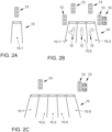
- road 10 comprises a single lane 10.1, in the vicinity of which a traffic light 13 is located.
- This case represents a control situation of low complexity, since traffic light 13 is typically uniquely assigned to lane 10.1.
- road 10 comprises three lanes 10.1, 10.2, 10.3, which further have lane markings 12, each of which designates a lane 10.1, 10.2, 10.3 for right-turning vehicles, for driving straight ahead, or for either driving straight ahead or turning left.
- Five traffic lights 13 are arranged in the vicinity of road 10. In the case shown here as an example, four of the traffic lights 13 are of the same design and relate to all three lanes 10.1, 10.2, 10.3, while the fifth traffic light 13 only regulates traffic turning right, which in the exemplary embodiment is limited to the right lane 10.3.
- road 10 comprises five lanes 10.1, 10.2, 10.3, 10.4, 10.5, in the vicinity of which three traffic lights 13 are arranged.
- vehicle's own position on one of the five lanes 10.1, 10.2, 10.3, 10.4, 10.5 must first be detected and then the signals relevant to the vehicle on its lane must be detected.
- traffic signs are provided, which, for the purposes of the following explanation of the embodiment, are treated in a common category with the road markings 12.
- further categories of traffic control devices can be provided and treated in different ways.
- the exemplary embodiment assumes at least partially automated driving of the vehicle 1, with the navigation unit 7 generating control signals based on which individual driving maneuvers are carried out automatically.
- the driver of the vehicle 1 nevertheless retains responsibility for the journey and can fully assume control at any time.
- Other exemplary embodiments may provide for other degrees of automation, such as fully automated driving along a predetermined route.
- Scenario interpretation is responsible for recognizing, processing, and interpreting the information relevant to the driving situation, especially traffic regulations.
- the passability of an intersection can be specified using three different types of traffic control devices: traffic signs, traffic lights, or no traffic signs, in which case general right-of-way rules apply, such as "right before left.”
- Traffic control can also be specified by a person, such as a hand signal.
- a central problem in assessing a traffic situation at an intersection, particularly in an urban context, is therefore correctly interpreting the various detected traffic light phases and/or traffic signs in order to plan the driving behavior of vehicle 1 and, if necessary, a subsequent automatically executed driving maneuver.
- passability is assessed based on probability distributions for various conditions.
- a passability assessment is generated, which can then be used to automatically determine and execute appropriate driving behavior at an urban intersection.
- the detection unit 2 of the vehicle 1 captures environmental data about the surroundings of the vehicle 1.
- the environmental data here includes, for example, road data, map data, ego position data, and traffic control data.
- the environmental data is further preprocessed such that an environmental perception is provided based on the raw data, with recognition already having been performed for some relevant elements.
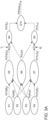
- Traffic sign recognition is performed in step S1, and traffic light recognition is performed in step S4. In this way, traffic signs or traffic light phases are recognized.
- map data is acquired in step S2, and data on the ego position of vehicle 1 is acquired in step S3. Based on the data acquired in step S3, an estimate of the ego position of vehicle 1 on road 10 is generated.
- the map data acquired in step S2 can be considered in various ways, for example, to determine the number of lanes present at a specific position on road 10.
- elements of the traffic infrastructure in the vicinity of the vehicle, or rather for the road section for which a passability assessment is to be generated are first detected based on the acquired environmental data.
- other method steps can be performed to acquire and evaluate information about the traffic situation.
- the data acquired and possibly pre-processed in steps S1 to S4 have certain uncertainties, for example due to inaccuracies in the sensors used in the acquisition unit 2, inaccuracies in the acquired map data and/or in steps for the recognition, in particular of signs and traffic lights 13.
- this is indicated using probability values which represent an uncertainty in the traffic sign recognition P(TSR j ) in step S1, an uncertainty in the map material P(AM) in step S2, an uncertainty in the determination of the ego position P(Pos) in step S3 and an uncertainty in the traffic light recognition P(TLR i ) in step S4.
- the index i refers to different traffic lights 13 and the index j to different road markings 12 and traffic signs. In the exemplary embodiment, it is assumed that any traffic signs present are viewed in the same way as road markings 12.
- step S5 traffic signs are assigned to lanes, taking into account the results of traffic sign recognition (step S1), map data acquisition (step S2), and ego position acquisition (step S3) with the respective uncertainties P(TSR j ) , P(AM) , and P(Pos) .
- P(TSA jf ) the probability assigned to lanes.
- step S7 the detected traffic lights 13 are assigned to lanes 10.1, 10.2, 10.3, 10.4, 10.5, taking into account the results of traffic light detection (step S4), map data acquisition (step S2), and ego position acquisition (step S3) with the respective uncertainties P(TLR i ) , P(AM) , and P(Pos) .
- a probability P(TLA if ) is generated.
- step S6 the vehicle 1 is assigned to one of the lanes 10.1, 10.2, 10.3, 10.4, 10.5 of the road 10, wherein in the exemplary embodiment the map data acquired in step S2 with the uncertainty P(AM) and the ego position determined in step S3 with the uncertainty P( Pos ) are taken into account, wherein an uncertainty P(LA f ) is determined for this step.
- the exemplary embodiment then aims to determine which traffic regulations are relevant for vehicle 1.
- a step S8 an assignment of the detected lane markings 12 and/or traffic signs to the vehicle 1 is carried out, wherein the assignment of the position of the vehicle 1 to the lanes 10.1, 10.2, 10.3, 10.4, 10.5 determined in step S6 and the assignment of the traffic regulations to the lanes 10.1, 10.2, 10.3, 10.4, 10.5 determined in step S5 with the respective probabilities P(LA f ) and P(TSA jf ) are taken into account.
- a confidence parameter ⁇ j is also used in this step S8 for the assignment of traffic signs, which confidence parameter is determined as a function of the complexity of the control situation for the road section whose passability is to be assessed.
- this is done by means of a machine learning method, whereby various methods known per se can be used.
- a support vector machine (SVM) can be used.
- a classifier is trained by training it using suitable training data, for example, provided by the system manufacturer.
- another machine learning method can be used, such as a neural network or an artificial neural network (ANN) or another machine learning method.
- various parameters can be used, which describe the control situation independently of the functioning of the actual procedure for determining the passability assessment, for example the number of detected traffic lights 13, the number of lanes 10.1, 10.2, 10.3, 10.4, 10.5, the lateral distance of the detected traffic lights 13 to the center of the various lanes 10.1, 10.2, 10.3, 10.4, 10.5, the distance of vehicle 1 to the traffic lights 13 and so on
- the assignment of the traffic signs to vehicle 1 determined in step S8 is associated with a probability P(TS l ) , which is also determined and whose index / stands for different categories of traffic signs.
- P(TS l ) a probability distribution is determined that indicates the probability with which a traffic sign of a certain category was assigned to the vehicle.
- An example of such a probability distribution is shown in Figure 3B shown, with a specific probability for each type of traffic sign represented as a bar chart. The example considers the following conditions: "No traffic sign detected,”"right before left,””priorityroad,””giveway,””stopsign.” Equivalent traffic regulations are included in each category.
- a step S9 the detected traffic lights 13 are assigned to the vehicle 1, wherein the assignment of the position of the vehicle 1 to the lanes 10.1, 10.2, 10.3, 10.4, 10.5 determined in step S6 and the assignment of the traffic lights 13 to the lanes 10.1, 10.2, 10.3, 10.4, 10.5 determined in step S7 are taken into account with the respective probabilities P(LA f ) and P(TLA if ) .
- a confidence parameter ⁇ i is used here for the assignment of traffic lights 13, which is determined in principle in the same way as described above.
- an SVM can be used, which is trained using suitable data, in particular by the manufacturer of the system, and which is particularly configured to determine a value between 0 and 1 which indicates a probability that the system will achieve a reliable assignment of traffic lights 13 to lanes 10.1, 10.2, 10.3, 10.4, 10.5 under the given circumstances.
- another machine learning method can be used alternatively or additionally, such as a neural network or an artificial neural network (ANN) or another machine learning method.
- a probability P(TL k ) assigned to the vehicle 1 is determined, the index k of which stands for different traffic light states.
- the traffic light states are determined based on the traffic light phases and denote different traffic regulations, which cannot necessarily be assigned to a unique traffic light phase. Different traffic light phases can be assigned to the same traffic regulation, by which the passability of an intersection is classified. For example, a green traffic light signal or a green traffic light with an arrow display can be provided, whereby both alternatives mean that passage for the vehicle is permitted. In such a case, the specific traffic light phase less relevant than the resulting traffic light status in deciding whether the vehicle may perform a certain driving maneuver.
- Figure 3C shows examples of the assignment of different traffic light phases to different traffic light states, designated by k .
- Traffic lights are shown, each with three illuminated surfaces, which can illuminate red (upper illuminated surface), yellow (middle) and/or green (bottom).
- the illuminated surfaces can also be round or arrow-shaped, with the arrow shapes pointing forward (or upwards), right, left, diagonally right or diagonally left.
- non-activated, i.e. dark, illuminated surfaces are indicated by unfilled outlines, while activated, i.e. illuminated, illuminated surfaces are shown as filled outlines.
- time-varying light signals can be considered as a separate traffic light phase and assigned to a traffic light state, in particular a flashing yellow light area.
- traffic light states can be defined in other ways, such as “traffic light state not recognized”, “traffic light off”, “entry not permitted”, “entry permitted”, “compatible turning”, “conditionally compatible turning”, “compatible left/right turning at red light” (e.g.: traffic light with green arrow), whereby alternatively or additionally other traffic light states can be defined.
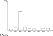
- a probability distribution is generated which is analogous to that in Figure 3B distribution shown and gives the probabilities for the different traffic light states denoted by k .
- Such a probability distribution is shown in 3D figure shown as an example, with the values for k plotted along the x-axis and the associated probabilities P(TL k ) plotted along the y-axis.
- P ( TL k ) P ( TL k
- the confidence factors ⁇ j , ⁇ i can be generated in a different way.
- confidence factors ⁇ j , ⁇ i can be fixedly specified for different conditions, for example, for certain categories of known traffic signs, for a certain number of lanes 10.1, 10.2, 10.3, 10.4, 10.5, traffic signs, road markings 12 and/or traffic lights 13 or for a certain ratio of the numbers of lanes 10.1, 10.2, 10.3, 10.4, 10.5 and traffic control devices to one another or for a certain road section.
- a passability assessment for the road section is generated based on the previously determined probabilities or wash-uniformity distributions.
- the passability assessment is output by transmitting a signal to the navigation unit 7, which determines a safe driving maneuver for the situation, in particular a target trajectory of the vehicle 1, and generates control signals such that the longitudinal and lateral guidance of the vehicle is controlled accordingly.
- a probability P(Pass m ) for specific passability states m is determined as a passability assessment, i.e., a passability probability distribution is determined.
- a predetermined set of different passability states is considered, and their probability is calculated.
- the navigation unit 7 can specify states that are relevant for route guidance and/or at least partially automatic travel along the specific route.
- the passability assessment can be determined in various ways, for example by means of a fuzzy logic method, a rule-based method or in another way.
- additional data can also be recorded and taken into account, for example specifications for a particular road section.
- a normalization i.e. the sum of all m probabilities P(Pass m ) is 1.
- the probability distributions for possible traffic light states k and the possible traffic signs l are normalized.
- the passability assessment is output according to the invention, with transmission to the navigation unit 7 being provided in the exemplary embodiment.
- the passability assessment is taken into account when executing driving maneuvers 3 of an at least partially automatic control system of the vehicle 1.
- an enable signal is generated based on the passability assessment, which includes information about whether the driving maneuver can be performed safely or not.
- the method according to the invention can be carried out for traffic lights and/or traffic signs and, alternatively or additionally, in an analogous manner for various types of traffic regulations, for example also for road markings, traffic signs at construction sites or similar regulations.
- the recorded probabilities are smoothed. For example, temporary fluctuations in the detection or assignment of a traffic sign, traffic light status, or lane may occur due to temporary obscuration by other road users or other effects.
- the Figures 4A to 4C The solid line shown represents the probability P determined for a specific traffic light state as a function of time.
- the probability is initially 0, then jumps to 1, briefly assumes the value 0 and then back to 1 and falls to 0 at the end of the shown range.
- a red traffic light is not visible at the beginning of the time interval under consideration, is then detected, is subsequently briefly obscured by another vehicle and is no longer registered at the end, for example after the traffic light has switched to a green signal.
- P* ( A k , n ) denotes the smoothed probability P ( A k , n ) of a particular traffic light signal A k for the time points n plotted along the abscissa.
- ⁇ is not chosen to be constant, but depends on certain conditions, for example for different traffic light states or traffic signs.
- a conditional exponential averaging ( Conditional Exponential Moving Average ; cEMA) is provided, where the smoothing parameter ⁇ is chosen depending on whether the value to be smoothed is decreasing ( ⁇ ab ) or increasing ( ⁇ zu ). Depending on whether the smoothing parameter for the increasing value ( ⁇ zu ) is larger or smaller than the smoothing parameter for the decreasing value ( ⁇ ab ), a conservative exponential averaging ( ⁇ zu ⁇ ab ) or a non-conservative exponential averaging ( ⁇ ab ⁇ zu ) can be achieved.
- cEMA Conditional Exponential Moving Average
- the smoothing parameter ⁇ can be calculated in various ways, depending on the traffic light state for which the probability is to be smoothed. For example, conservative smoothing can be selected for particularly critical signals, such as a detected prohibition to enter the intersection, such as a red light or a stop sign. In contrast, non-conservative smoothing can be selected for signals that are evaluated with caution in cases of doubt, such as a detected permission to enter the intersection, such as a green light or a "give way" sign.
Landscapes
- Physics & Mathematics (AREA)
- General Physics & Mathematics (AREA)
- Life Sciences & Earth Sciences (AREA)
- Atmospheric Sciences (AREA)
- Engineering & Computer Science (AREA)
- Chemical & Material Sciences (AREA)
- Analytical Chemistry (AREA)
- Multimedia (AREA)
- Theoretical Computer Science (AREA)
- Traffic Control Systems (AREA)
Claims (14)
- Procédé permettant de faire fonctionner un système d'assistance au conducteur pour un véhicule (1) sur une route (10), selon lequeldes données d'environnement sont collectées sur la route (10) et sur un environnement du véhicule (1) ; dans lequelles données d'environnement collectées comprennent des données routières sur le tracé de la section de la route (18) se trouvant devant le véhicule (1) dans le sens de la marche (F) sur une ou plusieurs voies de circulation (10.1, 10.2, 10.3, 10.4, 10.5) de la route (10) ainsi que sur des équipements de régulation du trafic (12, 13) ;à l'aide des données d'environnement collectées, au moins une régulation du trafic pour une section de route se trouvant devant le véhicule (1) dans le sens de la marche (F) est collectée et associée au véhicule (1) ; ainsi queune évaluation de praticabilité est générée et émise pour la section de route à l'aide de la régulation du trafic associée au véhicule (1) ;caractérisé en ce quel'évaluation de praticabilité est en outre générée à l'aide d'un paramètre de confiance (γj, θi) déterminé à l'aide des données d'environnement collectées et comprend une mesure d'une complexité d'une situation de régulation pour la section de route ; dans lequelle paramètre de confiance est déterminé sans la détermination concrète d'une association de la régulation du trafic au véhicule ; dans lequelle paramètre de confiance (γj, θi) diminue pour un nombre croissant de possibilités de combinaisons selon lesquelles les dispositifs de régulation du trafic (12, 13) peuvent être associés aux voies de circulation (10.1, 10.2, 10.3, 10.4, 10.5) de la route (10).
- Procédé selon l'une des revendications précédentes,
caractérisé en ce que
en outre, des données cartographiques sur la route (10) dans l'environnement du véhicule (1) sont collectées ; dans lequel les données cartographiques comprennent des informations sur un nombre de voies de circulation (10.1, 10.2, 10.3, 10.4, 10.5) de la route (10), la position de croisements et/ou la position de dispositifs de régulation du trafic (12, 13). - Procédé selon l'une des revendications précédentes,
caractérisé en ce que
les données d'environnement collectées comprennent des données d'ego-position ; et une distribution de probabilité d'ego-position pour l'ego-position du véhicule (1) est déterminée à l'aide des données d'ego-position. - Procédé selon la revendication 3,
caractérisé en ce que
la route (10) présente au moins deux voies de circulation (10.1, 10.2, 10.3, 10.4, 10.5) et la distribution de probabilité d'ego-position est déterminée par rapport aux voies de circulation (10.1, 10.2, 10.3, 10.4, 10.5) de la route (10). - Procédé selon la revendication 3 ou 4,
caractérisé en ce que
l'association de la régulation du trafic collectée au véhicule (1) s'effectue à l'aide de la distribution de probabilité d'ego-position. - Procédé selon l'une des revendications précédentes,
caractérisé en ce que
les données d'environnement collectées comprennent des données de régulation de trafic ; et pour collecter la régulation du trafic à l'aide des données de régulation du trafic, une distribution de probabilité de régulation du trafic est déterminée pour une pluralité de catégories de régulation du trafic prédéfinies. - Procédé selon l'une des revendications précédentes,
caractérisé en ce que
une distribution de probabilité d'association pour une association de dispositifs de régulation du trafic (12, 13) au véhicule (1) est déterminée à l'aide des données d'environnement collectées. - Procédé selon l'une des revendications précédentes,
caractérisé en ce que
l'évaluation de praticabilité comprend une distribution de probabilité de praticabilité. - Procédé selon l'une des revendications 3 à 8,
caractérisé en ce que
pour au moins l'une des distributions de probabilité déterminées, un lissage temporel est réalisé à l'aide d'un paramètre de lissage (α), dans lequel de préférence une moyenne glissante exponentielle, de manière particulièrement préférée une moyenne glissante exponentielle conditionnelle est réalisée. - Procédé selon la revendication 9,
caractérisé en ce que
un état de franchissement est déterminé à l'aide des données d'environnement collectées ; et le paramètre de lissage (α) est déterminé en fonction de l'état de franchissement. - Procédé selon l'une des revendications précédentes,
caractérisé en ce que
le paramètre de confiance (γj, θi) est déterminé au moyen d'un procédé d'apprentissage automatique. - Procédé selon l'une des revendications précédentes,
caractérisé en ce que
l'évaluation de praticabilité est générée pour une quantité donnée de manœuvres de conduite. - Système d'assistance au conducteur pour un véhicule (1) sur une route (10), comprenantune unité de collecte (2) par laquelle les données d'environnement sur la route (10) et sur un environnement du véhicule (1) peuvent être collectées ; dans lequelles données d'environnement collectées comprennent des données routières sur le tracé de la section de la route (18) se trouvant devant le véhicule (1) dans le sens de la marche (F) sur une ou plusieurs voies de circulation (10.1, 10.2, 10.3, 10.4, 10.5) de la route (10) ainsi que sur des équipements de régulation du trafic (12, 13) ;une unité de reconnaissance (4) par laquelle, à l'aide des données d'environnement collectées, au moins une régulation du trafic pour une section de route (11) se trouvant devant le véhicule (1) dans le sens de la marche peut être collectée ;une unité d'association (5), par laquelle la régulation du trafic collectée peut être associée au véhicule ; etune unité d'évaluation (6) par laquelle une évaluation de praticabilité peut être générée et émise pour la section de route à l'aide de la régulation du trafic associée au véhicule ;caractérisé en ce quel'évaluation de praticabilité peut en outre être générée à l'aide d'un paramètre de confiance (γj, θi) qui peut être déterminé à l'aide des données d'environnement collectées et qui comprend une mesure d'une complexité d'une situation de régulation pour la section de route ; dans lequelle paramètre de confiance peut être déterminé sans la détermination concrète d'une association de la régulation du trafic au véhicule ; dans lequelle paramètre de confiance (γj, θi) diminue pour un nombre croissant de possibilités de combinaisons selon lesquelles les dispositifs de régulation du trafic (12, 13) peuvent être associés aux voies de circulation (10.1, 10.2, 10.3, 10.4, 10.5) de la route (10).
- Système d'assistance au conducteur selon la revendication 13,
caractérisé en ce que
l'évaluation de praticabilité peut être reçue par une unité de commande ; dans lequel un signal de commande peut être généré à l'aide de l'évaluation de praticabilité, en fonction duquel une conduite au moins partiellement automatique du véhicule (1) peut être effectuée dans la zone de la section de route.
Applications Claiming Priority (1)
| Application Number | Priority Date | Filing Date | Title |
|---|---|---|---|
| DE102017203654.0A DE102017203654B4 (de) | 2017-03-07 | 2017-03-07 | Verfahren zum Betreiben eines Fahrerassistenzsystems für ein Fahrzeug auf einer Straße und Fahrerassistenzsystem |
Publications (2)
| Publication Number | Publication Date |
|---|---|
| EP3373268A1 EP3373268A1 (fr) | 2018-09-12 |
| EP3373268B1 true EP3373268B1 (fr) | 2025-05-07 |
Family
ID=61189277
Family Applications (1)
| Application Number | Title | Priority Date | Filing Date |
|---|---|---|---|
| EP18155954.3A Active EP3373268B1 (fr) | 2017-03-07 | 2018-02-09 | Procédé de fonctionnement d'un système d'aide à la conduite pour un véhicule sur une chaussée et système d'aide à la conduite |
Country Status (2)
| Country | Link |
|---|---|
| EP (1) | EP3373268B1 (fr) |
| DE (1) | DE102017203654B4 (fr) |
Families Citing this family (18)
| Publication number | Priority date | Publication date | Assignee | Title |
|---|---|---|---|---|
| JP7067067B2 (ja) | 2018-01-11 | 2022-05-16 | トヨタ自動車株式会社 | 信号機認識装置、及び自動運転システム |
| DE102019215095A1 (de) * | 2019-10-01 | 2021-04-01 | Volkswagen Aktiengesellschaft | Gütebestimmungsverfahren, Gütebestimmungsvorrichtung, Kraftfahrzeug |
| DE102020114837A1 (de) | 2020-06-04 | 2021-12-09 | Bayerische Motoren Werke Aktiengesellschaft | Computerimplementiertes Verfahren zur Trajektorienplanung für ein Fahrzeug |
| DE102020126675A1 (de) | 2020-10-12 | 2022-04-14 | Bayerische Motoren Werke Aktiengesellschaft | Fahrzeugführungssystem und Verfahren zum Betreiben einer Fahrfunktion im Anschluss an einem Anfahrvorgang |
| DE102020126680A1 (de) | 2020-10-12 | 2022-04-14 | Bayerische Motoren Werke Aktiengesellschaft | Fahrzeugführungssystem und Verfahren zum Betreiben einer Fahrfunktion bei Betätigung des Fahrpedals |
| DE102020126672A1 (de) | 2020-10-12 | 2022-04-14 | Bayerische Motoren Werke Aktiengesellschaft | Fahrzeugführungssystem und Verfahren zum Betreiben einer Fahrfunktion bei Vorliegen eines Widerspruchs mit Kartendaten |
| DE102020126679A1 (de) | 2020-10-12 | 2022-04-14 | Bayerische Motoren Werke Aktiengesellschaft | Fahrzeugführungssystem und Verfahren zum Betreiben einer Fahrfunktion in Abhängigkeit von einem Vorder-Fahrzeug |
| DE102020126685A1 (de) | 2020-10-12 | 2022-04-14 | Bayerische Motoren Werke Aktiengesellschaft | Fahrzeugführungssystem und Verfahren zum Betreiben einer Fahrfunktion in Abhängigkeit von der Entfernung zu einer Signalisierungseinheit |
| DE102020126678A1 (de) | 2020-10-12 | 2022-04-14 | Bayerische Motoren Werke Aktiengesellschaft | Fahrzeugführungssystem und Verfahren zum automatisierten Anfahren eines Fahrzeugs |
| DE102020126683A1 (de) | 2020-10-12 | 2022-04-14 | Bayerische Motoren Werke Aktiengesellschaft | Fahrzeugführungssystem und Verfahren zum Betreiben einer Fahrfunktion in Abhängigkeit von Umfeldinformation |
| DE102020126670A1 (de) | 2020-10-12 | 2022-04-14 | Bayerische Motoren Werke Aktiengesellschaft | Fahrzeugführungssystem und Verfahren zum Betreiben einer Fahrfunktion in unterschiedlichen Modi |
| DE102020126682A1 (de) | 2020-10-12 | 2022-04-14 | Bayerische Motoren Werke Aktiengesellschaft | Fahrzeugführungssystem und Verfahren zum Betreiben einer Fahrfunktion unter Berücksichtigung des Haltelinienabstands |
| DE102020126673A1 (de) | 2020-10-12 | 2022-04-14 | Bayerische Motoren Werke Aktiengesellschaft | Fahrzeugführungssystem und Verfahren zur Ausgabe von Information in Bezug auf eine Signalisierungseinheit |
| WO2022144956A1 (fr) | 2020-12-28 | 2022-07-07 | 本田技研工業株式会社 | Dispositif de commande de véhicule, procédé de commande de véhicule, et programme |
| DE102021104120A1 (de) | 2021-02-22 | 2022-08-25 | Bayerische Motoren Werke Aktiengesellschaft | Fahrzeugführungssystem und Verfahren zum Betreiben einer Fahrfunktion an einem Verkehrs-Knotenpunkt |
| DE102022201659B3 (de) | 2022-02-17 | 2023-08-03 | Continental Autonomous Mobility Germany GmbH | Fahrzeugsystem und Verfahren zur Zuordnung von Ampeln zu Fahrspuren |
| DE102022206511A1 (de) | 2022-06-28 | 2023-12-28 | Robert Bosch Gesellschaft mit beschränkter Haftung | Verfahren zum Steuern eines Ego-Fahrzeugs |
| DE102022127111A1 (de) | 2022-10-17 | 2024-04-18 | Bayerische Motoren Werke Aktiengesellschaft | Vorrichtung und Verfahren zum Betrieb einer Fahrfunktion auf einer Zufahrts-Fahrbahn zu einer Signalisierungseinheit |
Family Cites Families (9)
| Publication number | Priority date | Publication date | Assignee | Title |
|---|---|---|---|---|
| DE102005020429A1 (de) | 2005-04-29 | 2006-11-09 | Daimlerchrysler Ag | Verfahren und Vorrichtung zur Unterstützung des Fahrers beim Überqueren von Verkehrskreuzungen |
| DE102007021580C5 (de) | 2007-05-08 | 2026-02-12 | Cariad Se | Verfahren und Vorrichtung zum Ermitteln der fahrzeugrelevanten Verkehrszeichen |
| DE102011113019A1 (de) | 2011-07-14 | 2012-05-10 | Daimler Ag | Verfahren zur Ermittlung und Bewertung von Gefahren einer Situation zwischen zumindest zwei Verkehrsteilnehmern in einem Straßenkreuzungsbereich und Verfahren zur Unterstützung eines Fahrers beim Führen eines Fahrzeugs |
| DE102013005362A1 (de) | 2013-03-28 | 2013-10-10 | Daimler Ag | Verfahren zur Analyse einer Verkehrssituation |
| DE102013210725A1 (de) | 2013-06-10 | 2014-12-11 | Robert Bosch Gmbh | Verfahren und Vorrichtung zum Detektieren von Verkehrszeichen |
| DE102014011117A1 (de) | 2014-07-26 | 2016-01-28 | Audi Ag | Fahrerassistenzsystem, Kraftfahrzeug und Betriebsverfahren |
| DE102015219470A1 (de) * | 2014-10-10 | 2016-04-14 | Continental Teves Ag & Co. Ohg | Verfahren zum Handhaben einer Regelkarte |
| US20160293004A1 (en) | 2015-04-06 | 2016-10-06 | Umm Al-Qura University | Method and system for controlling and monitoring traffic light for optimizing wait time |
| DE102016219470A1 (de) | 2016-10-07 | 2018-04-12 | Robert Bosch Gmbh | Steueranordnung, Zugmaschine mit einer Steueranordnung und Verfahren für eine Steueranordnung |
-
2017
- 2017-03-07 DE DE102017203654.0A patent/DE102017203654B4/de active Active
-
2018
- 2018-02-09 EP EP18155954.3A patent/EP3373268B1/fr active Active
Also Published As
| Publication number | Publication date |
|---|---|
| DE102017203654B4 (de) | 2024-12-12 |
| DE102017203654A1 (de) | 2018-09-13 |
| EP3373268A1 (fr) | 2018-09-12 |
Similar Documents
| Publication | Publication Date | Title |
|---|---|---|
| EP3373268B1 (fr) | Procédé de fonctionnement d'un système d'aide à la conduite pour un véhicule sur une chaussée et système d'aide à la conduite | |
| EP3160813B1 (fr) | Procédé de création d'un modèle d'environnement d'un véhicule | |
| EP3253634B1 (fr) | Traitement de données de capteur pour un système d'aide à la conduite | |
| EP3095102B1 (fr) | Système et procédé permettant de détecter une situation de couloir de secours | |
| DE102015206144B4 (de) | Verfahren und Vorrichtung zum sicheren Abstellen eines Fahrzeuges | |
| DE102013101618B4 (de) | Fahrzeug-gestützte Verfolgungssteuervorrichtung | |
| DE112020004949T5 (de) | Fahrzeugbordvorrichtung und fahrunterstzützungsverfahren | |
| DE102023001318A1 (de) | Verfahren und Vorrichtung zum assistierten Fahren eines Fahrzeugs an Kreuzungen | |
| EP3271231B1 (fr) | Procédé et dispositif pour surveiller une trajectoire de consigne à parcourir par un véhicule au sujet de l'absence de collision | |
| DE102019217428B4 (de) | Verfahren zum Betreiben eines Fahrerassistenzsystems, Fahrerassistenzsystem und Fahrzeug | |
| DE102013211607A1 (de) | Verfahren und Vorrichtung zum Betreiben eines Fahrzeugs | |
| DE102013012324A1 (de) | Verfahren und Vorrichtung zur Fahrwegfindung | |
| DE102005025387A1 (de) | Verfahren und Vorrichtung zur Fahrerwahrnung bzw. zum aktiven Eingreifen in die Fahrdynamik, falls ein Verlassen der Fahrspur droht | |
| DE102015004605B4 (de) | Verfahren zum Betrieb eines Steuersystems einer Mobileinheit und Mobileinheit | |
| DE102021123270B3 (de) | Verfahren und Steuerschaltung zum Überprüfen, ob ein aktuell aktiver Fahrmodus innerhalb seiner ODD betrieben wird, sowie System und Backend-Server | |
| WO2019233777A1 (fr) | Système d'aide à la conduite | |
| WO2018024370A1 (fr) | Procédé de fonctionnement d'un véhicule et dispositif d'exécution du procédé | |
| WO2018188846A1 (fr) | Système d'assistance au conducteur pour un véhicule | |
| DE112020002139T5 (de) | Fahrzeugfahrsteuervorrichtung, Fahrzeugfahrsteuerverfahren und Computerprogrammprodukt | |
| DE102019215657A1 (de) | Fahrzeugsteuerungsstystem und -verfahren | |
| DE102016201190A1 (de) | Wendeassistent | |
| DE102020213514A1 (de) | Situationsabhängige Festlegung von Beobachtungsbereichen für zumindest teilautonom betriebene Kraftfahrzeuge | |
| DE102023000561A1 (de) | Verfahren und Vorrichtung zur Steuerung des Abbiegevorgangs eines Fahrzeugs | |
| EP3684645B1 (fr) | Raccourcissement de fonctions d'éclairage | |
| WO2019166540A1 (fr) | Procédé de fonctionnement d'un véhicule et véhicule autonome ou partiellement autonome |
Legal Events
| Date | Code | Title | Description |
|---|---|---|---|
| PUAI | Public reference made under article 153(3) epc to a published international application that has entered the european phase |
Free format text: ORIGINAL CODE: 0009012 |
|
| STAA | Information on the status of an ep patent application or granted ep patent |
Free format text: STATUS: THE APPLICATION HAS BEEN PUBLISHED |
|
| AK | Designated contracting states |
Kind code of ref document: A1 Designated state(s): AL AT BE BG CH CY CZ DE DK EE ES FI FR GB GR HR HU IE IS IT LI LT LU LV MC MK MT NL NO PL PT RO RS SE SI SK SM TR |
|
| AX | Request for extension of the european patent |
Extension state: BA ME |
|
| STAA | Information on the status of an ep patent application or granted ep patent |
Free format text: STATUS: REQUEST FOR EXAMINATION WAS MADE |
|
| 17P | Request for examination filed |
Effective date: 20190312 |
|
| RBV | Designated contracting states (corrected) |
Designated state(s): AL AT BE BG CH CY CZ DE DK EE ES FI FR GB GR HR HU IE IS IT LI LT LU LV MC MK MT NL NO PL PT RO RS SE SI SK SM TR |
|
| STAA | Information on the status of an ep patent application or granted ep patent |
Free format text: STATUS: EXAMINATION IS IN PROGRESS |
|
| 17Q | First examination report despatched |
Effective date: 20210326 |
|
| REG | Reference to a national code |
Ref country code: DE Ref legal event code: R079 Free format text: PREVIOUS MAIN CLASS: G08G0001010000 Ipc: G08G0001096200 Ref document number: 502018015785 Country of ref document: DE |
|
| GRAP | Despatch of communication of intention to grant a patent |
Free format text: ORIGINAL CODE: EPIDOSNIGR1 |
|
| STAA | Information on the status of an ep patent application or granted ep patent |
Free format text: STATUS: GRANT OF PATENT IS INTENDED |
|
| RIC1 | Information provided on ipc code assigned before grant |
Ipc: G08G 1/16 20060101ALI20250128BHEP Ipc: G08G 1/0967 20060101ALI20250128BHEP Ipc: G06V 20/58 20220101ALI20250128BHEP Ipc: G08G 1/01 20060101ALI20250128BHEP Ipc: G08G 1/0962 20060101AFI20250128BHEP |
|
| INTG | Intention to grant announced |
Effective date: 20250225 |
|
| GRAS | Grant fee paid |
Free format text: ORIGINAL CODE: EPIDOSNIGR3 |
|
| P01 | Opt-out of the competence of the unified patent court (upc) registered |
Free format text: CASE NUMBER: APP_9568/2025 Effective date: 20250226 |
|
| GRAA | (expected) grant |
Free format text: ORIGINAL CODE: 0009210 |
|
| STAA | Information on the status of an ep patent application or granted ep patent |
Free format text: STATUS: THE PATENT HAS BEEN GRANTED |
|
| AK | Designated contracting states |
Kind code of ref document: B1 Designated state(s): AL AT BE BG CH CY CZ DE DK EE ES FI FR GB GR HR HU IE IS IT LI LT LU LV MC MK MT NL NO PL PT RO RS SE SI SK SM TR |
|
| REG | Reference to a national code |
Ref country code: GB Ref legal event code: FG4D Free format text: NOT ENGLISH |
|
| REG | Reference to a national code |
Ref country code: CH Ref legal event code: EP |
|
| REG | Reference to a national code |
Ref country code: DE Ref legal event code: R096 Ref document number: 502018015785 Country of ref document: DE |
|
| REG | Reference to a national code |
Ref country code: IE Ref legal event code: FG4D Free format text: LANGUAGE OF EP DOCUMENT: GERMAN |
|
| REG | Reference to a national code |
Ref country code: NL Ref legal event code: MP Effective date: 20250507 |
|
| PG25 | Lapsed in a contracting state [announced via postgrant information from national office to epo] |
Ref country code: PT Free format text: LAPSE BECAUSE OF FAILURE TO SUBMIT A TRANSLATION OF THE DESCRIPTION OR TO PAY THE FEE WITHIN THE PRESCRIBED TIME-LIMIT Effective date: 20250908 Ref country code: FI Free format text: LAPSE BECAUSE OF FAILURE TO SUBMIT A TRANSLATION OF THE DESCRIPTION OR TO PAY THE FEE WITHIN THE PRESCRIBED TIME-LIMIT Effective date: 20250507 Ref country code: ES Free format text: LAPSE BECAUSE OF FAILURE TO SUBMIT A TRANSLATION OF THE DESCRIPTION OR TO PAY THE FEE WITHIN THE PRESCRIBED TIME-LIMIT Effective date: 20250507 |
|
| REG | Reference to a national code |
Ref country code: LT Ref legal event code: MG9D |
|
| PG25 | Lapsed in a contracting state [announced via postgrant information from national office to epo] |
Ref country code: GR Free format text: LAPSE BECAUSE OF FAILURE TO SUBMIT A TRANSLATION OF THE DESCRIPTION OR TO PAY THE FEE WITHIN THE PRESCRIBED TIME-LIMIT Effective date: 20250808 Ref country code: NO Free format text: LAPSE BECAUSE OF FAILURE TO SUBMIT A TRANSLATION OF THE DESCRIPTION OR TO PAY THE FEE WITHIN THE PRESCRIBED TIME-LIMIT Effective date: 20250807 |
|
| PG25 | Lapsed in a contracting state [announced via postgrant information from national office to epo] |
Ref country code: PL Free format text: LAPSE BECAUSE OF FAILURE TO SUBMIT A TRANSLATION OF THE DESCRIPTION OR TO PAY THE FEE WITHIN THE PRESCRIBED TIME-LIMIT Effective date: 20250507 Ref country code: NL Free format text: LAPSE BECAUSE OF FAILURE TO SUBMIT A TRANSLATION OF THE DESCRIPTION OR TO PAY THE FEE WITHIN THE PRESCRIBED TIME-LIMIT Effective date: 20250507 |
|
| PG25 | Lapsed in a contracting state [announced via postgrant information from national office to epo] |
Ref country code: BG Free format text: LAPSE BECAUSE OF FAILURE TO SUBMIT A TRANSLATION OF THE DESCRIPTION OR TO PAY THE FEE WITHIN THE PRESCRIBED TIME-LIMIT Effective date: 20250507 |
|
| PG25 | Lapsed in a contracting state [announced via postgrant information from national office to epo] |
Ref country code: HR Free format text: LAPSE BECAUSE OF FAILURE TO SUBMIT A TRANSLATION OF THE DESCRIPTION OR TO PAY THE FEE WITHIN THE PRESCRIBED TIME-LIMIT Effective date: 20250507 |
|
| PG25 | Lapsed in a contracting state [announced via postgrant information from national office to epo] |
Ref country code: RS Free format text: LAPSE BECAUSE OF FAILURE TO SUBMIT A TRANSLATION OF THE DESCRIPTION OR TO PAY THE FEE WITHIN THE PRESCRIBED TIME-LIMIT Effective date: 20250807 |
|
| PG25 | Lapsed in a contracting state [announced via postgrant information from national office to epo] |
Ref country code: IS Free format text: LAPSE BECAUSE OF FAILURE TO SUBMIT A TRANSLATION OF THE DESCRIPTION OR TO PAY THE FEE WITHIN THE PRESCRIBED TIME-LIMIT Effective date: 20250907 |
|
| PG25 | Lapsed in a contracting state [announced via postgrant information from national office to epo] |
Ref country code: LV Free format text: LAPSE BECAUSE OF FAILURE TO SUBMIT A TRANSLATION OF THE DESCRIPTION OR TO PAY THE FEE WITHIN THE PRESCRIBED TIME-LIMIT Effective date: 20250507 |
|
| PG25 | Lapsed in a contracting state [announced via postgrant information from national office to epo] |
Ref country code: SM Free format text: LAPSE BECAUSE OF FAILURE TO SUBMIT A TRANSLATION OF THE DESCRIPTION OR TO PAY THE FEE WITHIN THE PRESCRIBED TIME-LIMIT Effective date: 20250507 Ref country code: DK Free format text: LAPSE BECAUSE OF FAILURE TO SUBMIT A TRANSLATION OF THE DESCRIPTION OR TO PAY THE FEE WITHIN THE PRESCRIBED TIME-LIMIT Effective date: 20250507 |
|
| PG25 | Lapsed in a contracting state [announced via postgrant information from national office to epo] |
Ref country code: CZ Free format text: LAPSE BECAUSE OF FAILURE TO SUBMIT A TRANSLATION OF THE DESCRIPTION OR TO PAY THE FEE WITHIN THE PRESCRIBED TIME-LIMIT Effective date: 20250507 |
|
| PG25 | Lapsed in a contracting state [announced via postgrant information from national office to epo] |
Ref country code: EE Free format text: LAPSE BECAUSE OF FAILURE TO SUBMIT A TRANSLATION OF THE DESCRIPTION OR TO PAY THE FEE WITHIN THE PRESCRIBED TIME-LIMIT Effective date: 20250507 |
|
| PG25 | Lapsed in a contracting state [announced via postgrant information from national office to epo] |
Ref country code: SK Free format text: LAPSE BECAUSE OF FAILURE TO SUBMIT A TRANSLATION OF THE DESCRIPTION OR TO PAY THE FEE WITHIN THE PRESCRIBED TIME-LIMIT Effective date: 20250507 Ref country code: RO Free format text: LAPSE BECAUSE OF FAILURE TO SUBMIT A TRANSLATION OF THE DESCRIPTION OR TO PAY THE FEE WITHIN THE PRESCRIBED TIME-LIMIT Effective date: 20250507 |
|
| PG25 | Lapsed in a contracting state [announced via postgrant information from national office to epo] |
Ref country code: IT Free format text: LAPSE BECAUSE OF FAILURE TO SUBMIT A TRANSLATION OF THE DESCRIPTION OR TO PAY THE FEE WITHIN THE PRESCRIBED TIME-LIMIT Effective date: 20250507 |
|
| REG | Reference to a national code |
Ref country code: DE Ref legal event code: R097 Ref document number: 502018015785 Country of ref document: DE |
|
| PLBE | No opposition filed within time limit |
Free format text: ORIGINAL CODE: 0009261 |
|
| STAA | Information on the status of an ep patent application or granted ep patent |
Free format text: STATUS: NO OPPOSITION FILED WITHIN TIME LIMIT |
|
| REG | Reference to a national code |
Ref country code: CH Ref legal event code: L10 Free format text: ST27 STATUS EVENT CODE: U-0-0-L10-L00 (AS PROVIDED BY THE NATIONAL OFFICE) Effective date: 20260318 |
|
| PGFP | Annual fee paid to national office [announced via postgrant information from national office to epo] |
Ref country code: GB Payment date: 20260223 Year of fee payment: 9 |
|
| PGFP | Annual fee paid to national office [announced via postgrant information from national office to epo] |
Ref country code: DE Payment date: 20260228 Year of fee payment: 9 |
|
| 26N | No opposition filed |
Effective date: 20260210 |
|
| PGFP | Annual fee paid to national office [announced via postgrant information from national office to epo] |
Ref country code: FR Payment date: 20260227 Year of fee payment: 9 |