EP3373404A1 - Appareil permettant de détecter une défaillance d'un relais de puissance d'onduleur - Google Patents
Appareil permettant de détecter une défaillance d'un relais de puissance d'onduleur Download PDFInfo
- Publication number
- EP3373404A1 EP3373404A1 EP17182267.9A EP17182267A EP3373404A1 EP 3373404 A1 EP3373404 A1 EP 3373404A1 EP 17182267 A EP17182267 A EP 17182267A EP 3373404 A1 EP3373404 A1 EP 3373404A1
- Authority
- EP
- European Patent Office
- Prior art keywords
- voltage
- power relay
- fault
- inverter
- voltage drop
- Prior art date
- Legal status (The legal status is an assumption and is not a legal conclusion. Google has not performed a legal analysis and makes no representation as to the accuracy of the status listed.)
- Granted
Links
Images



Classifications
-
- H—ELECTRICITY
- H02—GENERATION; CONVERSION OR DISTRIBUTION OF ELECTRIC POWER
- H02H—EMERGENCY PROTECTIVE CIRCUIT ARRANGEMENTS
- H02H9/00—Emergency protective circuit arrangements for limiting excess current or voltage without disconnection
- H02H9/001—Emergency protective circuit arrangements for limiting excess current or voltage without disconnection limiting speed of change of electric quantities, e.g. soft switching on or off
-
- G—PHYSICS
- G01—MEASURING; TESTING
- G01R—MEASURING ELECTRIC VARIABLES; MEASURING MAGNETIC VARIABLES
- G01R31/00—Arrangements for testing electric properties; Arrangements for locating electric faults; Arrangements for electrical testing characterised by what is being tested not provided for elsewhere
- G01R31/327—Testing of circuit interrupters, switches or circuit-breakers
- G01R31/3277—Testing of circuit interrupters, switches or circuit-breakers of low voltage devices, e.g. domestic or industrial devices, such as motor protections, relays, rotation switches
-
- G—PHYSICS
- G01—MEASURING; TESTING
- G01R—MEASURING ELECTRIC VARIABLES; MEASURING MAGNETIC VARIABLES
- G01R31/00—Arrangements for testing electric properties; Arrangements for locating electric faults; Arrangements for electrical testing characterised by what is being tested not provided for elsewhere
- G01R31/327—Testing of circuit interrupters, switches or circuit-breakers
- G01R31/3277—Testing of circuit interrupters, switches or circuit-breakers of low voltage devices, e.g. domestic or industrial devices, such as motor protections, relays, rotation switches
- G01R31/3278—Testing of circuit interrupters, switches or circuit-breakers of low voltage devices, e.g. domestic or industrial devices, such as motor protections, relays, rotation switches of relays, solenoids or reed switches
-
- H—ELECTRICITY
- H02—GENERATION; CONVERSION OR DISTRIBUTION OF ELECTRIC POWER
- H02H—EMERGENCY PROTECTIVE CIRCUIT ARRANGEMENTS
- H02H1/00—Details of emergency protective circuit arrangements
- H02H1/0007—Details of emergency protective circuit arrangements concerning the detecting means
-
- G—PHYSICS
- G01—MEASURING; TESTING
- G01R—MEASURING ELECTRIC VARIABLES; MEASURING MAGNETIC VARIABLES
- G01R19/00—Arrangements for measuring currents or voltages or for indicating presence or sign thereof
- G01R19/165—Indicating that current or voltage is either above or below a predetermined value or within or outside a predetermined range of values
- G01R19/16566—Circuits and arrangements for comparing voltage or current with one or several thresholds and for indicating the result not covered by subgroups G01R19/16504, G01R19/16528, G01R19/16533
- G01R19/16571—Circuits and arrangements for comparing voltage or current with one or several thresholds and for indicating the result not covered by subgroups G01R19/16504, G01R19/16528, G01R19/16533 comparing AC or DC current with one threshold, e.g. load current, over-current, surge current or fault current
-
- G—PHYSICS
- G01—MEASURING; TESTING
- G01R—MEASURING ELECTRIC VARIABLES; MEASURING MAGNETIC VARIABLES
- G01R31/00—Arrangements for testing electric properties; Arrangements for locating electric faults; Arrangements for electrical testing characterised by what is being tested not provided for elsewhere
- G01R31/28—Testing of electronic circuits, e.g. by signal tracer
- G01R31/2832—Specific tests of electronic circuits not provided for elsewhere
- G01R31/2836—Fault-finding or characterising
-
- H—ELECTRICITY
- H02—GENERATION; CONVERSION OR DISTRIBUTION OF ELECTRIC POWER
- H02H—EMERGENCY PROTECTIVE CIRCUIT ARRANGEMENTS
- H02H7/00—Emergency protective circuit arrangements specially adapted for specific types of electric machines or apparatus or for sectionalised protection of cable or line systems, and effecting automatic switching in the event of an undesired change from normal working conditions
- H02H7/10—Emergency protective circuit arrangements specially adapted for specific types of electric machines or apparatus or for sectionalised protection of cable or line systems, and effecting automatic switching in the event of an undesired change from normal working conditions for converters; for rectifiers
-
- H—ELECTRICITY
- H02—GENERATION; CONVERSION OR DISTRIBUTION OF ELECTRIC POWER
- H02M—APPARATUS FOR CONVERSION BETWEEN AC AND AC, BETWEEN AC AND DC, OR BETWEEN DC AND DC, AND FOR USE WITH MAINS OR SIMILAR POWER SUPPLY SYSTEMS; CONVERSION OF DC OR AC INPUT POWER INTO SURGE OUTPUT POWER; CONTROL OR REGULATION THEREOF
- H02M5/00—Conversion of AC power input into AC power output, e.g. for change of voltage, for change of frequency, for change of number of phases
- H02M5/40—Conversion of AC power input into AC power output, e.g. for change of voltage, for change of frequency, for change of number of phases with intermediate conversion into DC
-
- H—ELECTRICITY
- H02—GENERATION; CONVERSION OR DISTRIBUTION OF ELECTRIC POWER
- H02H—EMERGENCY PROTECTIVE CIRCUIT ARRANGEMENTS
- H02H3/00—Emergency protective circuit arrangements for automatic disconnection directly responsive to an undesired change from normal electric working condition with or without subsequent reconnection ; integrated protection
- H02H3/02—Details
- H02H3/04—Details with warning or supervision in addition to disconnection, e.g. for indicating that protective apparatus has functioned
- H02H3/044—Checking correct functioning of protective arrangements, e.g. by simulating a fault
-
- H—ELECTRICITY
- H02—GENERATION; CONVERSION OR DISTRIBUTION OF ELECTRIC POWER
- H02M—APPARATUS FOR CONVERSION BETWEEN AC AND AC, BETWEEN AC AND DC, OR BETWEEN DC AND DC, AND FOR USE WITH MAINS OR SIMILAR POWER SUPPLY SYSTEMS; CONVERSION OF DC OR AC INPUT POWER INTO SURGE OUTPUT POWER; CONTROL OR REGULATION THEREOF
- H02M1/00—Details of apparatus for conversion
- H02M1/32—Means for protecting converters other than automatic disconnection
Definitions
- the present disclosure relates to an apparatus for detecting a fault in a power relay of an inverter.
- initial charging is carried out.
- a power relay connected in parallel to an initial charge resistor is opened.
- the initial charge resistor serves to prevent an inrush current during the initial charging.
- the power relay of the inverter is closed using a control signal for normal operation of the inverter.
- FIG. 1 is a diagram illustrating a current flow during the initial charging of the inverter.
- a converter stage 20 converts alternating current (AC) into direct current (DC) and provides a smoothing circuit with the direct current (DC).
- the smoothing unit typically includes a DC link in which a capacitor 13 is disposed, a resistor 11, and a power relay 12.
- a current flows as indicated by arrow 1 of FIG. 1 . This is to prevent an inrush current during introduction of the initial current.
- the power relay 12 is closed (ON) by a control signal generated inside the inverter, a current flows as indicated by arrow 2.
- the current flows as indicated by arrow 2 even when a motor 40 is driven, and an output current to an inverter stage 30 increases, such that the current (i dc ) also increases.
- the power relay 12 is damaged during driving of the motor 40, the current may flow again as indicated by arrow 1, such that the current flowing in the initial charge resistor 11 may deviates from rated capacity. As a result, the initial charge resistor 11 may be damaged and may causes heat, such that the internal structure of the inverter may also be damaged.
- an apparatus for detecting a fault in a power relay of an inverter includes: a voltage sensor configured to measure a voltage of a DC link; a current sensor configured to measure an output current to an inverter stage; a storage unit configured to store a resistance of an initial charge resistor, a time constant of a capacitor, and a reference voltage measured when no voltage drop occurs at the DC link; and a controller configured to determine, when the voltage drop occurs at the DC link, whether there is a fault in the power relay based on a difference between the reference voltage and a voltage measured after a period of time corresponding to the time constant has elapsed.
- the controller may compare the difference between the voltages with a voltage drop determined by the output current and the resistance, thereby determining whether there is a fault in the power relay.
- the controller may compare a rate of the voltage drop for each unit time measured when the voltage drop occurs with a rate calculated based on the measured output current, thereby determining whether the voltage drop lasts.
- the controller may determine whether there is a fault in the power relay when the voltage drop lasts for the time-constant period.
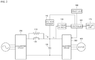
- FIG. 2 is a view illustrating an apparatus for detecting a fault in a power relay of an inverter according to an embodiment of the present disclosure.
- the apparatus for detecting a fault in a power relay of an inverter may include a voltage sensor 140, a current sensor 150, a controller 160, a display unit 170, and a storage unit 180.
- the apparatus for detecting a fault in a power relay of the inverter may be an internal element of the inverter or may be an external device or component detachably connected to the inverter. That is, the technical scope of the present disclosure is not limited by an apparatus for detecting a fault in the power relay of the inverter but encompasses an inverter capable of detecting a fault in the power relay.
- a converter stage 200 may convert an AC voltage into a DC voltage.
- the inverter stage 300 may convert a DC voltage smoothed by a capacitor 130 into a 3-phase AC voltage, and may provide the motor 400 with the 3-phase AC voltage.
- the initial charge resistor 110 may be disposed between the converter stage 200 and a DC link having the capacitor 130.
- the initial charge resistor 110 may also be connected in parallel to the power relay 120.
- the initial charge resistor 110 may prevent an inrush current from occurring during initial driving of the inverter.
- the power relay 120 may be disposed between the converter stage 200 and the DC link having the capacitor 130 and may be connected in parallel to the initial charge resistor 110.
- the power relay 120 remains opened (OFF) prior to driving of the inverter.
- the power relay 120 is closed (ON) according to a control signal generated inside the inverter after a predetermined time period has elapsed.
- the capacitor 130 may be disposed between the converter stage 200 and the inverter stage 300 and may smooth the DC voltage generated from the converter 200.
- the voltage sensor 140 may be connected to both ends of the capacitor 130 of the DC link, may measure a DC link voltage applied to the capacitor 130, and may provide the controller 160 with the measured DC link voltage.
- the DC link voltage may be measured at regular intervals of a unit time.
- the voltage sensor 140 may periodically measure the DC link voltage at intervals of 1 millisecond (ms).
- the current sensor 150 may measure an output current to the inverter stage 300 and may provide the controller 160 with the measured output current.
- the controller 160 may store the DC link voltage measured by the voltage sensor 140 in the storage unit 180.
- a reference voltage which is a voltage measured when the voltage is stabilized (i.e., when no voltage drop occurs), may be stored in the storage unit 180.
- the controller 160 may compare a rate of voltage drop per unit time measured by the voltage sensor 140 with a rate calculated using the output current measured by the current sensor 150, to determine whether there is a fault based on the results of comparison.
- the rate of voltage drop per unit time depends on the output current which is compared with the value acquired by dividing the calculated current ( i out ) by the time constant ⁇ . Voltage drop may occur for various reasons. Among voltage drops caused by various reasons, Expression 1 provides a basis for assuming that voltage drop is caused by damage to the power relay 120. That is, by using Expression 1, the controller 160 determines that there is a high possibility that the amount of voltage drop per unit time equals to the amount of voltage drop across the initial charge resistor 110 resulted from the damaged power relay 120.
- the current i dc may be calculated based on i out , which will be described later.
- the controller 160 may determine that voltage drop lasts if the left-hand side is larger than the right-hand side in Expression 1.
- the controller 160 may continuously store the DC link voltage in the storage unit 180 while it determines whether such voltage drop lasts.
- the controller 160 may determine that there is a fault in the power relay 120.
- the controller 160 may determine whether there is a fault in the power relay 120 by comparing the difference between the stored reference voltage with the voltage measured after the time constant has elapsed with the calculated value.
- the calculated value is the amount of voltage drop calculated using the output current and the resistance, which are compared as represented by Mathematical Expression 2: V i ⁇ V f i out / i std > i dc ⁇ R where V i denotes a reference voltage, and V f denotes a voltage measured after a time period corresponding to the time-constant has elapsed.
- the controller 160 may determine that there is a fault in the power relay 120 if the left-hand side is larger than the right-hand side in Expression 2, and may determine that there is no fault in the power relay 120 otherwise.
- the display unit 170 may be connected to the controller 160 to display information under the control of the controller 160 and may indicate whether there is a fault in the power relay 120.
- the display unit 170 may include a light-emitting diode (LED) lamp, which may be used to indicate whether there is a fault in the power relay 120. It is to be noted that this is merely illustrative.
- the display unit 170 may be implemented as a screen, such that a user can check if there is a fault from the screen.
- the display unit 170 When the display unit 170 is implemented as a screen, the display unit 170 may include a touchscreen. In this case, the user may check if there is a fault by touching the touchscreen.
- the display unit 170 may also be replaced with a speaker that can be incorporated in the inverter. If the controller determines that there is a fault in the power relay 120, it operates the speaker to audibly notify the user that there is the fault in the power relay 120.
- the storage unit 180 may be connected to the controller 160 and may store the resistance of the initial charge resistor 110, the time constant related to the capacitor 130, the reference voltage, the rated current, and the like.
- the storage unit 180 may also store the history of measured voltages measured while the controller 160 determines whether voltage drop lasts.
- FIG. 3 is a flowchart illustrating a method for detecting a fault in the power relay of the inverter according to an exemplary embodiment of the present disclosure.
- the method illustrated in FIG. 3 may be carried out by the apparatus for detecting a fault in the power relay of the inverter.
- the method is carried out by the apparatus for detecting a fault in the power relay of the inverter.
- the voltage sensor 140 may measure a reference voltage.
- the controller 160 may store the measured reference voltage in the storage unit 180.
- step S303 the controller 160 may determine whether to start detection.
- the determining whether to start detection means determining whether to start determining whether a voltage drop lasts.
- step S305 the controller 160 may receive information regarding a voltage measured at regular intervals and may determine whether voltage drop lasts. If voltage drop continuously occurs, it proceeds to step S307. Otherwise, it returns to step S301.
- step S307 the controller 160 may determine whether a time has elapsed more than the time constant after the detection has started. If so, it proceeds to step S309. Otherwise, it returns to step S305.
- step S309 the controller 160 may determine whether there is a fault in the power relay 120. It may be determined whether there is a fault based on Expression 2. If the left side is larger than the right side in Expression 2, it proceeds to step S311. Otherwise, it returns to step 5301.
- step S311 the controller 160 may determine whether there is a fault in the power relay 120.
- the controller 160 may log a fault in the power relay 120 in the storage unit 180.
- step S313 the controller 160 may indicate whether there is a fault in the power relay 120.
- FIG. 4 is a graph illustrating voltage drop over time.
- V dc denotes the voltage across the DC link, i.e., the voltage measured by the voltage sensor 140.
- a reference voltage is measured, and no voltage drop occurs. This point may indicate that the power relay 120 is operating normally.
- the controller 160 determines whether to start detection. It may be determined whether to start detection based on Expression 1.
- the controller 160 determines whether voltage drop lasts.
- the controller 160 determines whether there is a fault in the power relay 120.
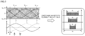
- FIG. 5 illustrates characteristics of the output current to the inverter 300.
- the view at the left upper side of FIG. 5 shows components of the 3-phase (i.e., a-phase, b-phase and c-phase) output voltage over time.
- the view at the left lower side of FIG. 5 shows components of the 3-phase output current over time.
- the view at the right side of FIG. 5 shows switching waveforms for a time period T s in the interval from ⁇ /2 to 5 ⁇ /6.
- the average of the output current for the time period T s becomes the i dc component of the output current.
- the output current during a time period ( T s - t a + t c ) becomes zero, and the output current during a time period (t a - t b ) may be i a .
- the output current during a time period ( t b - t c ) may be i a + i b .
- i dc 3 2 4 i out ⁇ m ⁇ pf m where m denotes a modulation index, and pf m denotes inverter efficiency.
- the controller 160 may use Expression 5 so as to calculate i dc in Expression 1 or Expression 2.
- the storage unit 180 may store the modulation index m and the inverter efficiency, and the controller 160 may use the stored modulation index and inverter efficiency to calculate Expression 5.
Landscapes
- Engineering & Computer Science (AREA)
- Physics & Mathematics (AREA)
- General Physics & Mathematics (AREA)
- Power Engineering (AREA)
- General Engineering & Computer Science (AREA)
- Inverter Devices (AREA)
Applications Claiming Priority (1)
| Application Number | Priority Date | Filing Date | Title |
|---|---|---|---|
| KR1020170028093A KR102307999B1 (ko) | 2017-03-06 | 2017-03-06 | 인버터의 파워릴레이 고장감지장치 |
Publications (2)
| Publication Number | Publication Date |
|---|---|
| EP3373404A1 true EP3373404A1 (fr) | 2018-09-12 |
| EP3373404B1 EP3373404B1 (fr) | 2021-08-25 |
Family
ID=59383455
Family Applications (1)
| Application Number | Title | Priority Date | Filing Date |
|---|---|---|---|
| EP17182267.9A Active EP3373404B1 (fr) | 2017-03-06 | 2017-07-20 | Appareil permettant de détecter une défaillance d'un relais de puissance d'onduleur |
Country Status (6)
| Country | Link |
|---|---|
| US (1) | US10594129B2 (fr) |
| EP (1) | EP3373404B1 (fr) |
| JP (1) | JP6441420B2 (fr) |
| KR (1) | KR102307999B1 (fr) |
| CN (1) | CN108535637B (fr) |
| ES (1) | ES2898696T3 (fr) |
Cited By (1)
| Publication number | Priority date | Publication date | Assignee | Title |
|---|---|---|---|---|
| CN110308341A (zh) * | 2019-05-09 | 2019-10-08 | 阳光电源股份有限公司 | 能量变换系统中的逆变模块检测方法、装置及系统 |
Families Citing this family (38)
| Publication number | Priority date | Publication date | Assignee | Title |
|---|---|---|---|---|
| US11054457B2 (en) | 2017-05-24 | 2021-07-06 | Cisco Technology, Inc. | Safety monitoring for cables transmitting data and power |
| US10809134B2 (en) | 2017-05-24 | 2020-10-20 | Cisco Technology, Inc. | Thermal modeling for cables transmitting data and power |
| US10541758B2 (en) | 2017-09-18 | 2020-01-21 | Cisco Technology, Inc. | Power delivery through an optical system |
| US11431420B2 (en) | 2017-09-18 | 2022-08-30 | Cisco Technology, Inc. | Power delivery through an optical system |
| US11093012B2 (en) | 2018-03-02 | 2021-08-17 | Cisco Technology, Inc. | Combined power, data, and cooling delivery in a communications network |
| US10732688B2 (en) | 2018-03-09 | 2020-08-04 | Cisco Technology, Inc. | Delivery of AC power with higher power PoE (power over ethernet) systems |
| US10281513B1 (en) | 2018-03-09 | 2019-05-07 | Cisco Technology, Inc. | Verification of cable application and reduced load cable removal in power over communications systems |
| US10631443B2 (en) | 2018-03-12 | 2020-04-21 | Cisco Technology, Inc. | Splitting of combined delivery power, data, and cooling in a communications network |
| US10672537B2 (en) | 2018-03-30 | 2020-06-02 | Cisco Technology, Inc. | Interface module for combined delivery power, data, and cooling at a network device |
| US10958471B2 (en) | 2018-04-05 | 2021-03-23 | Cisco Technology, Inc. | Method and apparatus for detecting wire fault and electrical imbalance for power over communications cabling |
| US10735105B2 (en) * | 2018-05-04 | 2020-08-04 | Cisco Technology, Inc. | High power and data delivery in a communications network with safety and fault protection |
| US11038307B2 (en) | 2018-05-25 | 2021-06-15 | Cisco Technology, Inc. | Cable power rating identification for power distribution over communications cabling |
| US10763749B2 (en) | 2018-11-14 | 2020-09-01 | Cisco Technology, Inc | Multi-resonant converter power supply |
| EP3779482B1 (fr) * | 2018-11-30 | 2024-01-10 | LG Energy Solution, Ltd. | Appareil et procédé de commande de commutateur |
| US10790997B2 (en) | 2019-01-23 | 2020-09-29 | Cisco Technology, Inc. | Transmission of pulse power and data in a communications network |
| US11061456B2 (en) | 2019-01-23 | 2021-07-13 | Cisco Technology, Inc. | Transmission of pulse power and data over a wire pair |
| CN112868175A (zh) * | 2019-01-28 | 2021-05-28 | 华为技术有限公司 | 一种解决共模电压干扰的设备、方法及系统 |
| US10680836B1 (en) | 2019-02-25 | 2020-06-09 | Cisco Technology, Inc. | Virtualized chassis with power-over-Ethernet for networking applications |
| KR102695940B1 (ko) * | 2019-03-12 | 2024-08-14 | 엘에스일렉트릭(주) | 인버터의 초기 충전 릴레이 고장 검출 장치 및 방법 |
| US11456883B2 (en) | 2019-03-13 | 2022-09-27 | Cisco Technology, Inc. | Multiple phase pulse power in a network communications system |
| US10849250B2 (en) | 2019-03-14 | 2020-11-24 | Cisco Technology, Inc. | Integration of power, data, cooling, and management in a network communications system |
| DE102019119868C5 (de) * | 2019-07-23 | 2026-03-19 | Danfoss Power Electronics A/S | Verfahren zum Bestimmen eines Gleichrichterstufenausgangsstroms und/oder von netzseitigen Strömen eines Frequenzumrichters |
| US12126399B2 (en) | 2019-11-01 | 2024-10-22 | Cisco Technology, Inc. | Fault managed power with dynamic and adaptive fault sensor |
| US11063630B2 (en) | 2019-11-01 | 2021-07-13 | Cisco Technology, Inc. | Initialization and synchronization for pulse power in a network system |
| JP6858834B1 (ja) * | 2019-12-11 | 2021-04-14 | 三菱電機株式会社 | 電力変換装置の制御装置 |
| US11252811B2 (en) | 2020-01-15 | 2022-02-15 | Cisco Technology, Inc. | Power distribution from point-of-load with cooling |
| US11088547B1 (en) | 2020-01-17 | 2021-08-10 | Cisco Technology, Inc. | Method and system for integration and control of power for consumer power circuits |
| US11853138B2 (en) | 2020-01-17 | 2023-12-26 | Cisco Technology, Inc. | Modular power controller |
| KR102828969B1 (ko) * | 2020-02-24 | 2025-07-02 | 엘에스일렉트릭(주) | 인버터 초기충전회로의 고장진단장치 및 그 방법 |
| KR102520182B1 (ko) * | 2020-02-24 | 2023-04-07 | 엘에스일렉트릭(주) | 인버터 초기충전회로의 고장진단장치 및 그 방법 |
| US11438183B2 (en) | 2020-02-25 | 2022-09-06 | Cisco Technology, Inc. | Power adapter for power supply unit |
| US11637497B2 (en) | 2020-02-28 | 2023-04-25 | Cisco Technology, Inc. | Multi-phase pulse power short reach distribution |
| US11307368B2 (en) | 2020-04-07 | 2022-04-19 | Cisco Technology, Inc. | Integration of power and optics through cold plates for delivery to electronic and photonic integrated circuits |
| US11320610B2 (en) | 2020-04-07 | 2022-05-03 | Cisco Technology, Inc. | Integration of power and optics through cold plate for delivery to electronic and photonic integrated circuits |
| KR102732156B1 (ko) * | 2021-07-01 | 2024-11-20 | (주)아이티공간 | 외란 검출을 통한 기기의 안전 관리시스템 |
| KR102667246B1 (ko) * | 2023-04-24 | 2024-05-17 | 박기만 | 차량에 직접 연결하여 충전이 가능한 차량용 점프 스타터 장치 |
| US12443251B2 (en) | 2023-07-27 | 2025-10-14 | Cisco Technology, Inc. | Fault managed power in a power distribution unit |
| US12298349B1 (en) * | 2024-06-28 | 2025-05-13 | Lunar Energy, Inc. | Grid relay fault detection |
Citations (4)
| Publication number | Priority date | Publication date | Assignee | Title |
|---|---|---|---|---|
| US5430636A (en) * | 1992-05-29 | 1995-07-04 | Mitsubishi Denki Kabushiki Kaisha | Inverter apparatus and inverter controlling method having fault protection |
| US20080150369A1 (en) * | 2006-12-22 | 2008-06-26 | Panasonic Ev Energy Co., Ltd. | Circuit controller, inrush current limiting circuit, inrush current limiting circuit with battery, inverter, and inverter with battery |
| US20110084704A1 (en) * | 2009-10-09 | 2011-04-14 | Kohei Myoen | Power supply device and method for making decision as to contactor weld of power supply device |
| US20130314012A1 (en) * | 2012-05-22 | 2013-11-28 | Lsis Co., Ltd. | Apparatus for diagnosing relay contact of electric vehicle and method thereof |
Family Cites Families (15)
| Publication number | Priority date | Publication date | Assignee | Title |
|---|---|---|---|---|
| JP2592709B2 (ja) | 1990-07-05 | 1997-03-19 | 富士写真フイルム株式会社 | 磁気記録媒体 |
| JP3243922B2 (ja) | 1994-03-16 | 2002-01-07 | 株式会社明電舎 | パワースイッチ素子の熱破損防止方法 |
| JP2000152643A (ja) | 1998-11-09 | 2000-05-30 | Hitachi Ltd | 電力変換装置 |
| JP2004032903A (ja) | 2002-06-26 | 2004-01-29 | Nissan Motor Co Ltd | 電動車両のリレー故障判定装置 |
| JP4265381B2 (ja) | 2003-11-13 | 2009-05-20 | 日産自動車株式会社 | リレーの故障判定装置およびリレーの故障判定方法 |
| JP2005184910A (ja) * | 2003-12-17 | 2005-07-07 | Suzuki Motor Corp | 車両用電気回路の故障判定装置 |
| JP5728914B2 (ja) | 2010-12-02 | 2015-06-03 | 富士電機株式会社 | インバータ装置 |
| KR101314114B1 (ko) | 2012-02-10 | 2013-10-04 | 주식회사 유라코퍼레이션 | 파워 릴레이 어셈블리 구동 장치 및 그 구동 방법 |
| KR101623230B1 (ko) | 2012-03-30 | 2016-05-20 | 엘에스산전 주식회사 | 인버터 제어장치 |
| KR101667635B1 (ko) | 2013-10-24 | 2016-10-19 | 엘에스산전 주식회사 | 고전압 릴레이 고장 진단 장치 및 이의 방법 |
| JP5820021B1 (ja) | 2014-06-13 | 2015-11-24 | ファナック株式会社 | 充電抵抗の保護手段を有するモータ制御装置 |
| JP6417892B2 (ja) * | 2014-11-21 | 2018-11-07 | 三菱自動車工業株式会社 | コンタクタ故障判定方法およびコンタクタ故障判定装置 |
| JP6200457B2 (ja) * | 2015-06-29 | 2017-09-20 | ファナック株式会社 | 初期充電回路の異常発熱を検出する手段を有するモータ駆動装置 |
| JP6269621B2 (ja) * | 2015-08-28 | 2018-01-31 | コベルコ建機株式会社 | ハイブリッド建設機械 |
| KR101689993B1 (ko) * | 2016-04-27 | 2016-12-26 | 엘에스산전 주식회사 | 릴레이 오작동 검출 장치 |
-
2017
- 2017-03-06 KR KR1020170028093A patent/KR102307999B1/ko active Active
- 2017-07-20 ES ES17182267T patent/ES2898696T3/es active Active
- 2017-07-20 EP EP17182267.9A patent/EP3373404B1/fr active Active
- 2017-07-25 JP JP2017143716A patent/JP6441420B2/ja not_active Expired - Fee Related
- 2017-07-26 US US15/660,224 patent/US10594129B2/en active Active
- 2017-08-01 CN CN201710648478.9A patent/CN108535637B/zh active Active
Patent Citations (4)
| Publication number | Priority date | Publication date | Assignee | Title |
|---|---|---|---|---|
| US5430636A (en) * | 1992-05-29 | 1995-07-04 | Mitsubishi Denki Kabushiki Kaisha | Inverter apparatus and inverter controlling method having fault protection |
| US20080150369A1 (en) * | 2006-12-22 | 2008-06-26 | Panasonic Ev Energy Co., Ltd. | Circuit controller, inrush current limiting circuit, inrush current limiting circuit with battery, inverter, and inverter with battery |
| US20110084704A1 (en) * | 2009-10-09 | 2011-04-14 | Kohei Myoen | Power supply device and method for making decision as to contactor weld of power supply device |
| US20130314012A1 (en) * | 2012-05-22 | 2013-11-28 | Lsis Co., Ltd. | Apparatus for diagnosing relay contact of electric vehicle and method thereof |
Cited By (2)
| Publication number | Priority date | Publication date | Assignee | Title |
|---|---|---|---|---|
| CN110308341A (zh) * | 2019-05-09 | 2019-10-08 | 阳光电源股份有限公司 | 能量变换系统中的逆变模块检测方法、装置及系统 |
| CN110308341B (zh) * | 2019-05-09 | 2021-09-03 | 阳光电源股份有限公司 | 能量变换系统中的逆变模块检测方法、装置及系统 |
Also Published As
| Publication number | Publication date |
|---|---|
| KR102307999B1 (ko) | 2021-09-30 |
| CN108535637A (zh) | 2018-09-14 |
| US20180254624A1 (en) | 2018-09-06 |
| EP3373404B1 (fr) | 2021-08-25 |
| JP2018148777A (ja) | 2018-09-20 |
| ES2898696T3 (es) | 2022-03-08 |
| US10594129B2 (en) | 2020-03-17 |
| KR20180101752A (ko) | 2018-09-14 |
| CN108535637B (zh) | 2020-12-11 |
| JP6441420B2 (ja) | 2018-12-19 |
Similar Documents
| Publication | Publication Date | Title |
|---|---|---|
| EP3373404B1 (fr) | Appareil permettant de détecter une défaillance d'un relais de puissance d'onduleur | |
| US11079444B2 (en) | Insulation detector and electric apparatus | |
| US11346893B2 (en) | Method and assessment unit for determining the remaining service life of a capacitor, and system | |
| US8552690B2 (en) | Method and system for automatically detecting a voltage of a battery | |
| US7064516B2 (en) | Motor driver | |
| US20160178706A1 (en) | Method and apparatus of detecting states of battery | |
| US8159228B2 (en) | Method for determining battery internal resistance | |
| US20110184560A1 (en) | Power sensor | |
| JP6916305B2 (ja) | 電圧不平衡判定方法、および電力変換装置 | |
| CN104155502B (zh) | 一种电压波动检测方法及系统 | |
| EP3138191B1 (fr) | Procédé de surveillance de la capacité de liaison cc dans des convertisseurs de puissance | |
| JP5829412B2 (ja) | インバータ装置及び平滑コンデンサの容量推定方法 | |
| US9716461B2 (en) | Motor drive having function of detecting circuit abnormality owing to entering foreign matter before significant abnormality occurs | |
| CN107211499A (zh) | 能够监测浪涌保护布置的使用的驱动器电路 | |
| JP2000152643A (ja) | 電力変換装置 | |
| JP2003068366A (ja) | センサ異常検出装置 | |
| JP2012007924A (ja) | 回転電機の絶縁診断装置 | |
| JP2962654B2 (ja) | 電解コンデンサの検査方法 | |
| KR100579923B1 (ko) | 전기자동차의 디씨 링크 커패시터 고장 판정방법 | |
| JP5549255B2 (ja) | エレベータの制御装置 | |
| CN110850195A (zh) | 一种链式svg功率模块的检测方法及装置 | |
| JPH02266820A (ja) | 電力変換装置用平滑コンデンサの寿命判定回路 | |
| CN110932649B (zh) | 掉电保护控制方法、控制模块 | |
| KR100675648B1 (ko) | 3상 교류 모터 인버터의 입력 결상 판별 방법 | |
| JP5188551B2 (ja) | 電源検査装置、電源検査方法、電源装置 |
Legal Events
| Date | Code | Title | Description |
|---|---|---|---|
| PUAI | Public reference made under article 153(3) epc to a published international application that has entered the european phase |
Free format text: ORIGINAL CODE: 0009012 |
|
| STAA | Information on the status of an ep patent application or granted ep patent |
Free format text: STATUS: THE APPLICATION HAS BEEN PUBLISHED |
|
| STAA | Information on the status of an ep patent application or granted ep patent |
Free format text: STATUS: REQUEST FOR EXAMINATION WAS MADE |
|
| AK | Designated contracting states |
Kind code of ref document: A1 Designated state(s): AL AT BE BG CH CY CZ DE DK EE ES FI FR GB GR HR HU IE IS IT LI LT LU LV MC MK MT NL NO PL PT RO RS SE SI SK SM TR |
|
| AX | Request for extension of the european patent |
Extension state: BA ME |
|
| 17P | Request for examination filed |
Effective date: 20180823 |
|
| RBV | Designated contracting states (corrected) |
Designated state(s): AL AT BE BG CH CY CZ DE DK EE ES FI FR GB GR HR HU IE IS IT LI LT LU LV MC MK MT NL NO PL PT RO RS SE SI SK SM TR |
|
| GRAP | Despatch of communication of intention to grant a patent |
Free format text: ORIGINAL CODE: EPIDOSNIGR1 |
|
| STAA | Information on the status of an ep patent application or granted ep patent |
Free format text: STATUS: GRANT OF PATENT IS INTENDED |
|
| INTG | Intention to grant announced |
Effective date: 20210415 |
|
| GRAS | Grant fee paid |
Free format text: ORIGINAL CODE: EPIDOSNIGR3 |
|
| GRAA | (expected) grant |
Free format text: ORIGINAL CODE: 0009210 |
|
| STAA | Information on the status of an ep patent application or granted ep patent |
Free format text: STATUS: THE PATENT HAS BEEN GRANTED |
|
| AK | Designated contracting states |
Kind code of ref document: B1 Designated state(s): AL AT BE BG CH CY CZ DE DK EE ES FI FR GB GR HR HU IE IS IT LI LT LU LV MC MK MT NL NO PL PT RO RS SE SI SK SM TR |
|
| REG | Reference to a national code |
Ref country code: CH Ref legal event code: EP |
|
| REG | Reference to a national code |
Ref country code: IE Ref legal event code: FG4D Ref country code: AT Ref legal event code: REF Ref document number: 1424779 Country of ref document: AT Kind code of ref document: T Effective date: 20210915 |
|
| REG | Reference to a national code |
Ref country code: DE Ref legal event code: R096 Ref document number: 602017044600 Country of ref document: DE |
|
| REG | Reference to a national code |
Ref country code: LT Ref legal event code: MG9D |
|
| REG | Reference to a national code |
Ref country code: NL Ref legal event code: MP Effective date: 20210825 |
|
| REG | Reference to a national code |
Ref country code: AT Ref legal event code: MK05 Ref document number: 1424779 Country of ref document: AT Kind code of ref document: T Effective date: 20210825 |
|
| PG25 | Lapsed in a contracting state [announced via postgrant information from national office to epo] |
Ref country code: SE Free format text: LAPSE BECAUSE OF FAILURE TO SUBMIT A TRANSLATION OF THE DESCRIPTION OR TO PAY THE FEE WITHIN THE PRESCRIBED TIME-LIMIT Effective date: 20210825 Ref country code: RS Free format text: LAPSE BECAUSE OF FAILURE TO SUBMIT A TRANSLATION OF THE DESCRIPTION OR TO PAY THE FEE WITHIN THE PRESCRIBED TIME-LIMIT Effective date: 20210825 Ref country code: LT Free format text: LAPSE BECAUSE OF FAILURE TO SUBMIT A TRANSLATION OF THE DESCRIPTION OR TO PAY THE FEE WITHIN THE PRESCRIBED TIME-LIMIT Effective date: 20210825 Ref country code: BG Free format text: LAPSE BECAUSE OF FAILURE TO SUBMIT A TRANSLATION OF THE DESCRIPTION OR TO PAY THE FEE WITHIN THE PRESCRIBED TIME-LIMIT Effective date: 20211125 Ref country code: AT Free format text: LAPSE BECAUSE OF FAILURE TO SUBMIT A TRANSLATION OF THE DESCRIPTION OR TO PAY THE FEE WITHIN THE PRESCRIBED TIME-LIMIT Effective date: 20210825 Ref country code: PT Free format text: LAPSE BECAUSE OF FAILURE TO SUBMIT A TRANSLATION OF THE DESCRIPTION OR TO PAY THE FEE WITHIN THE PRESCRIBED TIME-LIMIT Effective date: 20211227 Ref country code: NO Free format text: LAPSE BECAUSE OF FAILURE TO SUBMIT A TRANSLATION OF THE DESCRIPTION OR TO PAY THE FEE WITHIN THE PRESCRIBED TIME-LIMIT Effective date: 20211125 Ref country code: HR Free format text: LAPSE BECAUSE OF FAILURE TO SUBMIT A TRANSLATION OF THE DESCRIPTION OR TO PAY THE FEE WITHIN THE PRESCRIBED TIME-LIMIT Effective date: 20210825 Ref country code: FI Free format text: LAPSE BECAUSE OF FAILURE TO SUBMIT A TRANSLATION OF THE DESCRIPTION OR TO PAY THE FEE WITHIN THE PRESCRIBED TIME-LIMIT Effective date: 20210825 |
|
| PG25 | Lapsed in a contracting state [announced via postgrant information from national office to epo] |
Ref country code: PL Free format text: LAPSE BECAUSE OF FAILURE TO SUBMIT A TRANSLATION OF THE DESCRIPTION OR TO PAY THE FEE WITHIN THE PRESCRIBED TIME-LIMIT Effective date: 20210825 Ref country code: LV Free format text: LAPSE BECAUSE OF FAILURE TO SUBMIT A TRANSLATION OF THE DESCRIPTION OR TO PAY THE FEE WITHIN THE PRESCRIBED TIME-LIMIT Effective date: 20210825 Ref country code: GR Free format text: LAPSE BECAUSE OF FAILURE TO SUBMIT A TRANSLATION OF THE DESCRIPTION OR TO PAY THE FEE WITHIN THE PRESCRIBED TIME-LIMIT Effective date: 20211126 |
|
| REG | Reference to a national code |
Ref country code: ES Ref legal event code: FG2A Ref document number: 2898696 Country of ref document: ES Kind code of ref document: T3 Effective date: 20220308 |
|
| PG25 | Lapsed in a contracting state [announced via postgrant information from national office to epo] |
Ref country code: NL Free format text: LAPSE BECAUSE OF FAILURE TO SUBMIT A TRANSLATION OF THE DESCRIPTION OR TO PAY THE FEE WITHIN THE PRESCRIBED TIME-LIMIT Effective date: 20210825 |
|
| PG25 | Lapsed in a contracting state [announced via postgrant information from national office to epo] |
Ref country code: DK Free format text: LAPSE BECAUSE OF FAILURE TO SUBMIT A TRANSLATION OF THE DESCRIPTION OR TO PAY THE FEE WITHIN THE PRESCRIBED TIME-LIMIT Effective date: 20210825 |
|
| REG | Reference to a national code |
Ref country code: DE Ref legal event code: R097 Ref document number: 602017044600 Country of ref document: DE |
|
| PG25 | Lapsed in a contracting state [announced via postgrant information from national office to epo] |
Ref country code: SM Free format text: LAPSE BECAUSE OF FAILURE TO SUBMIT A TRANSLATION OF THE DESCRIPTION OR TO PAY THE FEE WITHIN THE PRESCRIBED TIME-LIMIT Effective date: 20210825 Ref country code: SK Free format text: LAPSE BECAUSE OF FAILURE TO SUBMIT A TRANSLATION OF THE DESCRIPTION OR TO PAY THE FEE WITHIN THE PRESCRIBED TIME-LIMIT Effective date: 20210825 Ref country code: RO Free format text: LAPSE BECAUSE OF FAILURE TO SUBMIT A TRANSLATION OF THE DESCRIPTION OR TO PAY THE FEE WITHIN THE PRESCRIBED TIME-LIMIT Effective date: 20210825 Ref country code: EE Free format text: LAPSE BECAUSE OF FAILURE TO SUBMIT A TRANSLATION OF THE DESCRIPTION OR TO PAY THE FEE WITHIN THE PRESCRIBED TIME-LIMIT Effective date: 20210825 Ref country code: CZ Free format text: LAPSE BECAUSE OF FAILURE TO SUBMIT A TRANSLATION OF THE DESCRIPTION OR TO PAY THE FEE WITHIN THE PRESCRIBED TIME-LIMIT Effective date: 20210825 Ref country code: AL Free format text: LAPSE BECAUSE OF FAILURE TO SUBMIT A TRANSLATION OF THE DESCRIPTION OR TO PAY THE FEE WITHIN THE PRESCRIBED TIME-LIMIT Effective date: 20210825 |
|
| PLBE | No opposition filed within time limit |
Free format text: ORIGINAL CODE: 0009261 |
|
| STAA | Information on the status of an ep patent application or granted ep patent |
Free format text: STATUS: NO OPPOSITION FILED WITHIN TIME LIMIT |
|
| PGFP | Annual fee paid to national office [announced via postgrant information from national office to epo] |
Ref country code: GB Payment date: 20220607 Year of fee payment: 6 |
|
| 26N | No opposition filed |
Effective date: 20220527 |
|
| PG25 | Lapsed in a contracting state [announced via postgrant information from national office to epo] |
Ref country code: SI Free format text: LAPSE BECAUSE OF FAILURE TO SUBMIT A TRANSLATION OF THE DESCRIPTION OR TO PAY THE FEE WITHIN THE PRESCRIBED TIME-LIMIT Effective date: 20210825 |
|
| PGFP | Annual fee paid to national office [announced via postgrant information from national office to epo] |
Ref country code: ES Payment date: 20220811 Year of fee payment: 6 |
|
| PG25 | Lapsed in a contracting state [announced via postgrant information from national office to epo] |
Ref country code: MC Free format text: LAPSE BECAUSE OF FAILURE TO SUBMIT A TRANSLATION OF THE DESCRIPTION OR TO PAY THE FEE WITHIN THE PRESCRIBED TIME-LIMIT Effective date: 20210825 |
|
| REG | Reference to a national code |
Ref country code: CH Ref legal event code: PL |
|
| REG | Reference to a national code |
Ref country code: BE Ref legal event code: MM Effective date: 20220731 |
|
| PG25 | Lapsed in a contracting state [announced via postgrant information from national office to epo] |
Ref country code: LU Free format text: LAPSE BECAUSE OF NON-PAYMENT OF DUE FEES Effective date: 20220720 Ref country code: LI Free format text: LAPSE BECAUSE OF NON-PAYMENT OF DUE FEES Effective date: 20220731 Ref country code: FR Free format text: LAPSE BECAUSE OF NON-PAYMENT OF DUE FEES Effective date: 20220731 Ref country code: CH Free format text: LAPSE BECAUSE OF NON-PAYMENT OF DUE FEES Effective date: 20220731 |
|
| PG25 | Lapsed in a contracting state [announced via postgrant information from national office to epo] |
Ref country code: BE Free format text: LAPSE BECAUSE OF NON-PAYMENT OF DUE FEES Effective date: 20220731 |
|
| PG25 | Lapsed in a contracting state [announced via postgrant information from national office to epo] |
Ref country code: IE Free format text: LAPSE BECAUSE OF NON-PAYMENT OF DUE FEES Effective date: 20220720 |
|
| P01 | Opt-out of the competence of the unified patent court (upc) registered |
Effective date: 20230625 |
|
| GBPC | Gb: european patent ceased through non-payment of renewal fee |
Effective date: 20230720 |
|
| PG25 | Lapsed in a contracting state [announced via postgrant information from national office to epo] |
Ref country code: HU Free format text: LAPSE BECAUSE OF FAILURE TO SUBMIT A TRANSLATION OF THE DESCRIPTION OR TO PAY THE FEE WITHIN THE PRESCRIBED TIME-LIMIT; INVALID AB INITIO Effective date: 20170720 |
|
| PG25 | Lapsed in a contracting state [announced via postgrant information from national office to epo] |
Ref country code: MK Free format text: LAPSE BECAUSE OF FAILURE TO SUBMIT A TRANSLATION OF THE DESCRIPTION OR TO PAY THE FEE WITHIN THE PRESCRIBED TIME-LIMIT Effective date: 20210825 Ref country code: CY Free format text: LAPSE BECAUSE OF FAILURE TO SUBMIT A TRANSLATION OF THE DESCRIPTION OR TO PAY THE FEE WITHIN THE PRESCRIBED TIME-LIMIT Effective date: 20210825 Ref country code: GB Free format text: LAPSE BECAUSE OF NON-PAYMENT OF DUE FEES Effective date: 20230720 |
|
| REG | Reference to a national code |
Ref country code: ES Ref legal event code: FD2A Effective date: 20240829 |
|
| PG25 | Lapsed in a contracting state [announced via postgrant information from national office to epo] |
Ref country code: MT Free format text: LAPSE BECAUSE OF FAILURE TO SUBMIT A TRANSLATION OF THE DESCRIPTION OR TO PAY THE FEE WITHIN THE PRESCRIBED TIME-LIMIT Effective date: 20210825 |
|
| PG25 | Lapsed in a contracting state [announced via postgrant information from national office to epo] |
Ref country code: ES Free format text: LAPSE BECAUSE OF NON-PAYMENT OF DUE FEES Effective date: 20230721 |
|
| PG25 | Lapsed in a contracting state [announced via postgrant information from national office to epo] |
Ref country code: ES Free format text: LAPSE BECAUSE OF NON-PAYMENT OF DUE FEES Effective date: 20230721 |
|
| PGFP | Annual fee paid to national office [announced via postgrant information from national office to epo] |
Ref country code: DE Payment date: 20250609 Year of fee payment: 9 |
|
| PGFP | Annual fee paid to national office [announced via postgrant information from national office to epo] |
Ref country code: IT Payment date: 20250610 Year of fee payment: 9 |
|
| PG25 | Lapsed in a contracting state [announced via postgrant information from national office to epo] |
Ref country code: TR Free format text: LAPSE BECAUSE OF FAILURE TO SUBMIT A TRANSLATION OF THE DESCRIPTION OR TO PAY THE FEE WITHIN THE PRESCRIBED TIME-LIMIT Effective date: 20210825 |