EP3373457A1 - Verrou électromécanique - Google Patents
Verrou électromécanique Download PDFInfo
- Publication number
- EP3373457A1 EP3373457A1 EP17159758.6A EP17159758A EP3373457A1 EP 3373457 A1 EP3373457 A1 EP 3373457A1 EP 17159758 A EP17159758 A EP 17159758A EP 3373457 A1 EP3373457 A1 EP 3373457A1
- Authority
- EP
- European Patent Office
- Prior art keywords
- lock
- loop
- circuit
- antenna
- coupled
- Prior art date
- Legal status (The legal status is an assumption and is not a legal conclusion. Google has not performed a legal analysis and makes no representation as to the accuracy of the status listed.)
- Withdrawn
Links
Images


Classifications
-
- H—ELECTRICITY
- H04—ELECTRIC COMMUNICATION TECHNIQUE
- H04B—TRANSMISSION
- H04B5/00—Near-field transmission systems, e.g. inductive or capacitive transmission systems
- H04B5/70—Near-field transmission systems, e.g. inductive or capacitive transmission systems specially adapted for specific purposes
- H04B5/79—Near-field transmission systems, e.g. inductive or capacitive transmission systems specially adapted for specific purposes for data transfer in combination with power transfer
-
- E—FIXED CONSTRUCTIONS
- E05—LOCKS; KEYS; WINDOW OR DOOR FITTINGS; SAFES
- E05B—LOCKS; ACCESSORIES THEREFOR; HANDCUFFS
- E05B47/00—Operating or controlling locks or other fastening devices by electric or magnetic means
-
- G—PHYSICS
- G07—CHECKING-DEVICES
- G07C—TIME OR ATTENDANCE REGISTERS; REGISTERING OR INDICATING THE WORKING OF MACHINES; GENERATING RANDOM NUMBERS; VOTING OR LOTTERY APPARATUS; ARRANGEMENTS, SYSTEMS OR APPARATUS FOR CHECKING NOT PROVIDED FOR ELSEWHERE
- G07C9/00—Individual registration on entry or exit
- G07C9/00174—Electronically operated locks; Circuits therefor; Nonmechanical keys therefor, e.g. passive or active electrical keys or other data carriers without mechanical keys
-
- G—PHYSICS
- G07—CHECKING-DEVICES
- G07C—TIME OR ATTENDANCE REGISTERS; REGISTERING OR INDICATING THE WORKING OF MACHINES; GENERATING RANDOM NUMBERS; VOTING OR LOTTERY APPARATUS; ARRANGEMENTS, SYSTEMS OR APPARATUS FOR CHECKING NOT PROVIDED FOR ELSEWHERE
- G07C9/00—Individual registration on entry or exit
- G07C9/00174—Electronically operated locks; Circuits therefor; Nonmechanical keys therefor, e.g. passive or active electrical keys or other data carriers without mechanical keys
- G07C9/00944—Details of construction or manufacture
-
- G—PHYSICS
- G07—CHECKING-DEVICES
- G07C—TIME OR ATTENDANCE REGISTERS; REGISTERING OR INDICATING THE WORKING OF MACHINES; GENERATING RANDOM NUMBERS; VOTING OR LOTTERY APPARATUS; ARRANGEMENTS, SYSTEMS OR APPARATUS FOR CHECKING NOT PROVIDED FOR ELSEWHERE
- G07C9/00—Individual registration on entry or exit
- G07C9/20—Individual registration on entry or exit involving the use of a pass
-
- H—ELECTRICITY
- H02—GENERATION; CONVERSION OR DISTRIBUTION OF ELECTRIC POWER
- H02J—ELECTRIC POWER NETWORKS; CIRCUIT ARRANGEMENTS OR SYSTEMS FOR SUPPLYING OR DISTRIBUTING ELECTRIC POWER; SYSTEMS FOR STORING ELECTRIC ENERGY
- H02J50/00—Circuit arrangements or systems for wireless supply or distribution of electric power
- H02J50/10—Circuit arrangements or systems for wireless supply or distribution of electric power using inductive coupling
- H02J50/12—Circuit arrangements or systems for wireless supply or distribution of electric power using inductive coupling of the resonant type
-
- H—ELECTRICITY
- H02—GENERATION; CONVERSION OR DISTRIBUTION OF ELECTRIC POWER
- H02J—ELECTRIC POWER NETWORKS; CIRCUIT ARRANGEMENTS OR SYSTEMS FOR SUPPLYING OR DISTRIBUTING ELECTRIC POWER; SYSTEMS FOR STORING ELECTRIC ENERGY
- H02J7/00—Circuit arrangements for charging or discharging batteries or for supplying loads from batteries
- H02J7/40—Circuit arrangements for charging or discharging batteries or for supplying loads from batteries characterised by the exchange of charge or discharge related data
- H02J7/47—Arrangements for checking compatibility or authentication between one component, e.g. a battery or a battery charger, and another component, e.g. a power source
-
- H—ELECTRICITY
- H04—ELECTRIC COMMUNICATION TECHNIQUE
- H04B—TRANSMISSION
- H04B5/00—Near-field transmission systems, e.g. inductive or capacitive transmission systems
- H04B5/40—Near-field transmission systems, e.g. inductive or capacitive transmission systems characterised by components specially adapted for near-field transmission
- H04B5/43—Antennas
-
- E—FIXED CONSTRUCTIONS
- E05—LOCKS; KEYS; WINDOW OR DOOR FITTINGS; SAFES
- E05B—LOCKS; ACCESSORIES THEREFOR; HANDCUFFS
- E05B47/00—Operating or controlling locks or other fastening devices by electric or magnetic means
- E05B2047/0048—Circuits, feeding, monitoring
- E05B2047/0057—Feeding
-
- G—PHYSICS
- G07—CHECKING-DEVICES
- G07C—TIME OR ATTENDANCE REGISTERS; REGISTERING OR INDICATING THE WORKING OF MACHINES; GENERATING RANDOM NUMBERS; VOTING OR LOTTERY APPARATUS; ARRANGEMENTS, SYSTEMS OR APPARATUS FOR CHECKING NOT PROVIDED FOR ELSEWHERE
- G07C9/00—Individual registration on entry or exit
- G07C9/00174—Electronically operated locks; Circuits therefor; Nonmechanical keys therefor, e.g. passive or active electrical keys or other data carriers without mechanical keys
- G07C2009/00634—Power supply for the lock
-
- G—PHYSICS
- G07—CHECKING-DEVICES
- G07C—TIME OR ATTENDANCE REGISTERS; REGISTERING OR INDICATING THE WORKING OF MACHINES; GENERATING RANDOM NUMBERS; VOTING OR LOTTERY APPARATUS; ARRANGEMENTS, SYSTEMS OR APPARATUS FOR CHECKING NOT PROVIDED FOR ELSEWHERE
- G07C9/00—Individual registration on entry or exit
- G07C9/00174—Electronically operated locks; Circuits therefor; Nonmechanical keys therefor, e.g. passive or active electrical keys or other data carriers without mechanical keys
- G07C2009/00753—Electronically operated locks; Circuits therefor; Nonmechanical keys therefor, e.g. passive or active electrical keys or other data carriers without mechanical keys operated by active electrical keys
- G07C2009/00769—Electronically operated locks; Circuits therefor; Nonmechanical keys therefor, e.g. passive or active electrical keys or other data carriers without mechanical keys operated by active electrical keys with data transmission performed by wireless means
- G07C2009/00777—Electronically operated locks; Circuits therefor; Nonmechanical keys therefor, e.g. passive or active electrical keys or other data carriers without mechanical keys operated by active electrical keys with data transmission performed by wireless means by induction
-
- H—ELECTRICITY
- H04—ELECTRIC COMMUNICATION TECHNIQUE
- H04B—TRANSMISSION
- H04B5/00—Near-field transmission systems, e.g. inductive or capacitive transmission systems
- H04B5/70—Near-field transmission systems, e.g. inductive or capacitive transmission systems specially adapted for specific purposes
- H04B5/77—Near-field transmission systems, e.g. inductive or capacitive transmission systems specially adapted for specific purposes for interrogation
Definitions
- the invention relates to electromechanical locks, especially to locks that are near-field communication -powered.
- Electromechanical locks are replacing traditional mechanical locks. Electromechanical locks require an external supply of electric power, a battery inside the lock, a battery inside the key, or means for generating electric power within the lock making the lock user-powered. Electromechanical locks provide many benefits over traditional locks. They provide better security, and the control of keys or security tokens is easier.
- NFC near-field communication
- a near-field communication reader brought to near vicinity of a lock may generate an electric field and the lock may harvest operating power form the electric field.
- the harvesting operation is essential regarding the operation of the lock and it should be as reliable and efficient as possible.
- the present invention seeks to provide an improved solution for realizing energy harvesting of an electromechanical lock.
- a near-field communication -powered electromechanical lock comprising: an antenna circuit comprising a main resonator loop comprising of a first loop antenna coupled in series with a first capacitor in a first part of the loop and a second capacitor in a second part of the loop, and coupled in parallel with a third capacitor between the first part and the second part; a passive near-field communication tag circuit coupled with the antenna circuit; an energy storage coupled with the passive near-filed communication tag circuit; a microcontroller powered by the energy storage; an electrically-controlled actuator powered by the energy storage; one or more auxiliary resonator loops, each auxiliary resonator loop comprising of an auxiliary loop antenna coupled in series with fourth capacitor in a first part of the loop and a fifth capacitor in a second part of the loop, and coupled in parallel with a sixth capacitor between the first part and the second part; wherein, the antenna circuit is configured to harvest electric energy from a near-field communication reader, store energy through the passive near-field communication tag circuit
- an electronic key is utilized for wirelessly opening an electromechanical wireless and batteryless lock.
- the key may be carried by a person as a part of his wireless communication device.
- Figure 1 illustrates an embodiment of an electronic locking system. A user is about to open a door, and the user has a communication device 100.
- the communication device 100 refers to a portable computing device. Such computing devices include wireless mobile communication devices such as a mobile phone, a smartphone, a tablet computer, a personal digital assistant (PDA) or a personal computer.
- the communication device 100 may have a wireless network channel connection to a wireless network.
- Some examples of different wireless networks are the universal mobile telecommunications system (UMTS) radio access network (UTRAN or E-UTRAN), long term evolution (LTE, known also as E-UTRA), long term evolution advanced (LTE-A), 5th generation mobile networks, Wireless Local Area Network (WLAN) based on IEEE 802.11stardard, worldwide interoperability for microwave access (WiMAX), personal communications services (PCS) and systems using ultra-wideband (UWB) technology.
- IEEE refers to the Institute of Electrical and Electronics Engineers or any other suitable standard/non-standard wireless communication means.
- the communication device 100 is equipped with a SIM/UICC card.
- SIM Subscriber Identity Module
- UICC Universal Integrated Circuit Card
- the smart cards comprise a processor, I/O circuits and a memory, typically a few hundred kilobytes or larger.
- the memory and the smart card may be utilised for example in to ensure the integrity and security of all kinds of personal data.
- the memory may store applications and storage space for data.
- the communication device 100 is equipped with a short-range wireless communication unit configured to communicate with other respective short-range units upon detecting such a unit.
- NFC Near Field Communication
- NFC is a set of short-range wireless technologies, typically requiring a distance of 4 cm or less.
- NFC operates at 13.56 MHz on ISO/IEC 18000-3 air interface and at rates ranging from 106 kbit/s to 424 kbit/s.
- NFC always involves an initiator and a target; the initiator actively generates a radio frequency (RF) field that can power a passive target.
- RF radio frequency
- the initiator device In a passive communication mode the initiator device provides a carrier field and the target device answers by modulating the existing field. In this mode, the target device may draw its operating power from the initiator-provided electromagnetic field, thus making the target device a transponder. In an embodiment, the communication device 100 is acting as the initiator.
- the door comprises an electromechanical lock 102.
- the lock comprises a lock interface 104, a lock antenna 112 and locking mechanism 114.
- An example of the locking mechanism is a lock bolt.
- the lock interface 104 may be a doorknob turn knob or handle, for example.
- the lock antenna 112 is connected to an electronic circuitry 116 of the lock.
- the circuitry comprises a short-range communication device.
- the device may be an NFC transceiver. In an embodiment, the NFC transceiver of the lock is the target device.
- an authentication procedure may be executed.
- the communication device reads an authentication challenge from the electronic circuitry 116 of the lock.
- the communication device 100 computes a response and transmits the response to the electronic circuitry of the lock.
- the lock performs the authentication.
- the lock authenticates the response.
- the response is authenticated against the challenge. If the authentication succeeds the lock is set to an openable state. All operations above may be performed using the power received from the short-range transmission of the communication device.
- the above described challenge-response authentication method is just an example of the authentication procedure; also other authentication procedures can be used.
- the authentication tasks may be divided between the lock and the communication device symmetrically or asymmetrically.
- the lock and the device proceed with the authentication procedure.
- the lock may authenticate the communication device
- the communication device may authenticate the lock or the both parties authenticate each other.
- the lock 102 thus comprises an electronic circuitry 116 and a lock antenna 112, a lock interface 104 and a locking mechanism 114 as previously described.
- the electronic circuitry 116 may be implemented as one or more integrated circuits, such as application-specific integrated circuits ASIC. Other embodiments are also feasible, such as a circuit built of separate logic components, or memory units and one or more processors with software. A hybrid of these different embodiments is also feasible. When selecting the method of implementation, a person skilled in the art will consider the requirements set on the power consumption of the device, production costs, and production volumes, for example.
- the electronic circuitry 116 may be configured to execute computer program instructions for executing computer processes.
- the lock 102 further comprises an electrically operated actuator 118 which may set the locking mechanism 114 to openable or closed state.
- Figure 2 illustrates an embodiment of a NFC-powered electronic locking system in more detail.
- the lock comprises the electronic circuitry 116 and the lock antenna 112. It may be noted that figure 2 is a simplified diagram illustrating an embodiment and actual lock may comprise also other parts and connections not disclosed in the figure for simplicity.
- the lock antenna 112 comprises an antenna circuit 200 comprising a main resonator loop 202.
- the main resonator loop 202 comprises a first loop antenna 204 coupled in series with a first capacitor 206 in a first part of the loop and a second capacitor 208 in a second part of the loop, and coupled in parallel with a third capacitor 210 between the first part and the second part.
- the electronic circuitry 116 comprises a passive near-field communication tag circuit 212 coupled 214 with the antenna circuit 200.
- the lock further comprises an energy storage 216 coupled with the passive near-filed communication tag circuit 212 and a microcontroller 218 powered by the energy storage 216.
- the lock further comprises a controller 220 for controlling actuator, the controller and the actuator both being powered by the energy storage 216.
- the lock further comprises in the antenna part 112 one or more auxiliary resonator loops 224.
- Each auxiliary resonator loop may comprise an auxiliary loop antenna 226 coupled in series with fourth capacitor 228 in a first part of the loop and a fifth capacitor 230 in a second part of the loop, and coupled in parallel with a sixth capacitor 232 between the first part and the second part.
- capacitors there number of capacitors may vary.
- the communication device may act as an initiator device and provide an electromagnetic carrier field.
- the first loop antenna 204 of the main resonator loop 202 detects the carrier field and the main resonator loop 202 may draw operating power from the initiator-provided electromagnetic field.
- the resonator loop begins to resonate and a resonator current is induced.
- the current is fed to the near-field communication tag circuit 212 which is configured to store the received power into the power storage 216.
- the stored energy is used for the operation of the lock, provide sufficient electric power to the microcontroller and the actuator for operations such as communication with the communication device, authentication, and controlling the actuator so that the lock may be set in an openable state if authentication is successful.
- the antenna part comprises the one or more auxiliary resonator loops 224 and main resonator loop 202 harvests energy from the electromagnetic field.
- the structure and properties of the one or more auxiliary resonator loops are similar to the main resonator loop.
- the one or more auxiliary resonator loops 224 are in the same electromagnetic field as the main resonator loop.
- the one or more auxiliary resonator loops are floating, i.e. that are not electrically connected to any other device or component.
- the auxiliary resonator loops balance the operation of the antenna circuit.
- the magnitude of energy transfer of the main resonator loop is such that the electrical properties of the transfer are not necessarily stable. For example, the resonance frequency of a single main resonator loop may be unsteady.
- the matching of the antenna circuit with the electromagnetic field increases. Return loss (so called S11) is better while the bandwidth remains the same on the used 13.56 MHz frequency.
- the antenna matching remains good especially when the communication device transmitting the electromagnetic field is relatively near (approximately within a few centimeters, typically below 2 cm) from the antenna circuit. This distance is typical for this kind of usage situations.
- the above balancing effects enable the main resonator loop to gather more energy than a standalone resonator loop of a similar size and properties could gather.
- the antenna circuit 200 and the one or more auxiliary resonator loops 224 are positioned inside the turn-knob 104 of the lock.
- the lock comprises a convex surface and the antenna circuit 200 and the one or more auxiliary resonator loops 224 are positioned under the convex surface.
- the convex surface may be the surface of the turn-knob 104 of the lock.
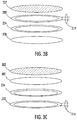
- FIGS 3A , 3B and 3C illustrate example of the realisation of the lock antenna 112.
- the lock antenna 112 comprises a circuit board 300.
- the main resonator loop 202 may be on one side of the circuit board 300 and the one or more auxiliary resonator loops 224 may be on the other side of the circuit board.
- an electromagnetic shield 302 such as a ferrite placed between the lock resonator loops 202, 224, and the passive near-field communication tag circuit, the energy storage, the microcontroller and the actuator.
- the main resonator loop 202 and the one or more auxiliary resonator loops 224 may be on the same side of the circuit board 300 with the one or more auxiliary resonator loops closer to the circuit board.
- the main resonator loop 202 and the one or more auxiliary resonator loops 224 may be on the same side of the circuit board 300 with the electromagnetic shield 302 on the other side of the circuit board.
- the inductance of the antennas have an effect on the values of the capacitors and whether there is a ferrite disc between the lock antenna 112 and the electronic circuit 116.
- the capacitors C1, C2, C4 and C5 may have values of 220pF and capacitors C3, C6 may have values of 15pF.
- the main resonator loop 202 the total parallel capacitance is formed from the capacitance value 50 pF of the NFC chip and the value of C3.
- the additional resonator loops 224 the total parallel capacitance is formed from the capacitance value 50 pF of C6 and the capacitance of the NFC chip and.
- these values are merely illustrative.
Landscapes
- Engineering & Computer Science (AREA)
- Computer Networks & Wireless Communication (AREA)
- Power Engineering (AREA)
- Physics & Mathematics (AREA)
- General Physics & Mathematics (AREA)
- Signal Processing (AREA)
- Manufacturing & Machinery (AREA)
- Near-Field Transmission Systems (AREA)
Priority Applications (2)
| Application Number | Priority Date | Filing Date | Title |
|---|---|---|---|
| EP17159758.6A EP3373457A1 (fr) | 2017-03-08 | 2017-03-08 | Verrou électromécanique |
| PCT/EP2018/055242 WO2018162367A1 (fr) | 2017-03-08 | 2018-03-05 | Verrou électromécanique |
Applications Claiming Priority (1)
| Application Number | Priority Date | Filing Date | Title |
|---|---|---|---|
| EP17159758.6A EP3373457A1 (fr) | 2017-03-08 | 2017-03-08 | Verrou électromécanique |
Publications (1)
| Publication Number | Publication Date |
|---|---|
| EP3373457A1 true EP3373457A1 (fr) | 2018-09-12 |
Family
ID=58266885
Family Applications (1)
| Application Number | Title | Priority Date | Filing Date |
|---|---|---|---|
| EP17159758.6A Withdrawn EP3373457A1 (fr) | 2017-03-08 | 2017-03-08 | Verrou électromécanique |
Country Status (2)
| Country | Link |
|---|---|
| EP (1) | EP3373457A1 (fr) |
| WO (1) | WO2018162367A1 (fr) |
Cited By (4)
| Publication number | Priority date | Publication date | Assignee | Title |
|---|---|---|---|---|
| CN109658567A (zh) * | 2018-12-14 | 2019-04-19 | 武汉泰可电气股份有限公司 | 一种基于低功耗物联网技术的智能在线五防系统 |
| CN114868161A (zh) * | 2019-12-04 | 2022-08-05 | 尼特莫公司 | 具有机电钥匙的智能锁 |
| US11804084B2 (en) | 2013-09-10 | 2023-10-31 | Lockfob, Llc | Contactless electronic access control system |
| US12027001B2 (en) | 2020-03-31 | 2024-07-02 | Lockfob, Llc | Electronic access control |
Citations (2)
| Publication number | Priority date | Publication date | Assignee | Title |
|---|---|---|---|---|
| US20150332527A1 (en) * | 2011-11-11 | 2015-11-19 | Iloq Oy | Electromechanical lock |
| US20160087687A1 (en) * | 2008-09-27 | 2016-03-24 | Witricity Corporation | Communication in a wireless power transmission system |
-
2017
- 2017-03-08 EP EP17159758.6A patent/EP3373457A1/fr not_active Withdrawn
-
2018
- 2018-03-05 WO PCT/EP2018/055242 patent/WO2018162367A1/fr not_active Ceased
Patent Citations (2)
| Publication number | Priority date | Publication date | Assignee | Title |
|---|---|---|---|---|
| US20160087687A1 (en) * | 2008-09-27 | 2016-03-24 | Witricity Corporation | Communication in a wireless power transmission system |
| US20150332527A1 (en) * | 2011-11-11 | 2015-11-19 | Iloq Oy | Electromechanical lock |
Cited By (7)
| Publication number | Priority date | Publication date | Assignee | Title |
|---|---|---|---|---|
| US11804084B2 (en) | 2013-09-10 | 2023-10-31 | Lockfob, Llc | Contactless electronic access control system |
| US12211328B2 (en) | 2013-09-10 | 2025-01-28 | Lockfob, Llc | Contactless electronic access control system |
| CN109658567A (zh) * | 2018-12-14 | 2019-04-19 | 武汉泰可电气股份有限公司 | 一种基于低功耗物联网技术的智能在线五防系统 |
| CN114868161A (zh) * | 2019-12-04 | 2022-08-05 | 尼特莫公司 | 具有机电钥匙的智能锁 |
| US12170394B2 (en) | 2019-12-04 | 2024-12-17 | Netatmo | Smart lock having an electromechanical key |
| US12027001B2 (en) | 2020-03-31 | 2024-07-02 | Lockfob, Llc | Electronic access control |
| US12430966B2 (en) | 2020-03-31 | 2025-09-30 | Lockfob, Llc | Electronic access control |
Also Published As
| Publication number | Publication date |
|---|---|
| WO2018162367A1 (fr) | 2018-09-13 |
Similar Documents
| Publication | Publication Date | Title |
|---|---|---|
| US9406178B2 (en) | Electromechanical lock | |
| US11164407B2 (en) | Near field communication tag | |
| EP4274107B1 (fr) | Système comportant plusieurs puces nfc | |
| EP2388930B1 (fr) | Protection contre les surtensions dans un dispositif capable d'effectuer des communications de champ proche | |
| US20170338562A1 (en) | Wireless antenna structure | |
| EP3373457A1 (fr) | Verrou électromécanique | |
| EP2919202B1 (fr) | Dispositif de verrouillage à alimentation RFID | |
| US11610089B2 (en) | Apparatus | |
| US10102697B2 (en) | High-Q and over-coupled near-field RFID reader antenna for improved tag read range | |
| EP3291129B1 (fr) | Transpondeur rfid et procédé permettant de lui fournir de l'énergie | |
| US9680443B2 (en) | Apparatus and method for operating at least two antennas for a motor vehicle, and near-field communication network | |
| CN212709312U (zh) | 卡片式汽车门禁装置 | |
| JP2023031535A (ja) | 認証システム、およびユーザインターフェース装置 | |
| CN103516415A (zh) | 通信控制方法、转接装置及射频通讯系统 | |
| HK1132063A1 (en) | A multimode rfid tag and its operation method |
Legal Events
| Date | Code | Title | Description |
|---|---|---|---|
| PUAI | Public reference made under article 153(3) epc to a published international application that has entered the european phase |
Free format text: ORIGINAL CODE: 0009012 |
|
| AK | Designated contracting states |
Kind code of ref document: A1 Designated state(s): AL AT BE BG CH CY CZ DE DK EE ES FI FR GB GR HR HU IE IS IT LI LT LU LV MC MK MT NL NO PL PT RO RS SE SI SK SM TR |
|
| AX | Request for extension of the european patent |
Extension state: BA ME |
|
| STAA | Information on the status of an ep patent application or granted ep patent |
Free format text: STATUS: THE APPLICATION IS DEEMED TO BE WITHDRAWN |
|
| 18D | Application deemed to be withdrawn |
Effective date: 20190313 |