EP3373597A1 - Microphone à montage en surface à profil bas - Google Patents
Microphone à montage en surface à profil bas Download PDFInfo
- Publication number
- EP3373597A1 EP3373597A1 EP17159485.6A EP17159485A EP3373597A1 EP 3373597 A1 EP3373597 A1 EP 3373597A1 EP 17159485 A EP17159485 A EP 17159485A EP 3373597 A1 EP3373597 A1 EP 3373597A1
- Authority
- EP
- European Patent Office
- Prior art keywords
- condenser microphone
- back plate
- layer
- conductive
- microphone
- Prior art date
- Legal status (The legal status is an assumption and is not a legal conclusion. Google has not performed a legal analysis and makes no representation as to the accuracy of the status listed.)
- Granted
Links
Images

Classifications
-
- H—ELECTRICITY
- H04—ELECTRIC COMMUNICATION TECHNIQUE
- H04R—LOUDSPEAKERS, MICROPHONES, GRAMOPHONE PICK-UPS OR LIKE ACOUSTIC ELECTROMECHANICAL TRANSDUCERS; ELECTRIC HEARING AIDS; PUBLIC ADDRESS SYSTEMS
- H04R19/00—Electrostatic transducers
- H04R19/04—Microphones
-
- H—ELECTRICITY
- H04—ELECTRIC COMMUNICATION TECHNIQUE
- H04R—LOUDSPEAKERS, MICROPHONES, GRAMOPHONE PICK-UPS OR LIKE ACOUSTIC ELECTROMECHANICAL TRANSDUCERS; ELECTRIC HEARING AIDS; PUBLIC ADDRESS SYSTEMS
- H04R1/00—Details of transducers, loudspeakers or microphones
- H04R1/02—Casings; Cabinets ; Supports therefor; Mountings therein
- H04R1/04—Structural association of microphone with electric circuitry therefor
-
- H—ELECTRICITY
- H04—ELECTRIC COMMUNICATION TECHNIQUE
- H04R—LOUDSPEAKERS, MICROPHONES, GRAMOPHONE PICK-UPS OR LIKE ACOUSTIC ELECTROMECHANICAL TRANSDUCERS; ELECTRIC HEARING AIDS; PUBLIC ADDRESS SYSTEMS
- H04R1/00—Details of transducers, loudspeakers or microphones
- H04R1/08—Mouthpieces; Microphones; Attachments therefor
-
- H—ELECTRICITY
- H04—ELECTRIC COMMUNICATION TECHNIQUE
- H04R—LOUDSPEAKERS, MICROPHONES, GRAMOPHONE PICK-UPS OR LIKE ACOUSTIC ELECTROMECHANICAL TRANSDUCERS; ELECTRIC HEARING AIDS; PUBLIC ADDRESS SYSTEMS
- H04R19/00—Electrostatic transducers
- H04R19/005—Electrostatic transducers using semiconductor materials
-
- H—ELECTRICITY
- H04—ELECTRIC COMMUNICATION TECHNIQUE
- H04R—LOUDSPEAKERS, MICROPHONES, GRAMOPHONE PICK-UPS OR LIKE ACOUSTIC ELECTROMECHANICAL TRANSDUCERS; ELECTRIC HEARING AIDS; PUBLIC ADDRESS SYSTEMS
- H04R7/00—Diaphragms for electromechanical transducers; Cones
- H04R7/02—Diaphragms for electromechanical transducers; Cones characterised by the construction
- H04R7/04—Plane diaphragms
- H04R7/06—Plane diaphragms comprising a plurality of sections or layers
-
- H—ELECTRICITY
- H04—ELECTRIC COMMUNICATION TECHNIQUE
- H04R—LOUDSPEAKERS, MICROPHONES, GRAMOPHONE PICK-UPS OR LIKE ACOUSTIC ELECTROMECHANICAL TRANSDUCERS; ELECTRIC HEARING AIDS; PUBLIC ADDRESS SYSTEMS
- H04R2410/00—Microphones
- H04R2410/07—Mechanical or electrical reduction of wind noise generated by wind passing a microphone
Definitions
- the invention relates to a surface mountable condenser microphone comprising a diaphragm spaced by a spacer from a conductive capacitor layer arranged on a surface of a back plate.
- Document EP 1 649 718 B1 discloses a surface mountable condenser microphone to mount it on a printed circuit board of e.g. a mobile phone.
- the condenser microphone disclosed is an electret condenser microphone that comprises a cylindrical shaped housing which holds a diaphragm and a back plate spaced by a spacer and a processing circuit arranged under the back plate.
- the mechanical elements of this surface mountable condenser microphone are built and arranged in a way that the housing of the microphone projects substantially over the surface it is mounted on. This is acceptable for use cases in a mobile phone, but would be too high and bulky for other use cases.
- Such other use cases are for instance surface mountable microphones used to glue them on airplane surfaces for in-flight testing or to glue them on the blade of a wind turbine.
- Document US 2011/192212 A1 discloses such a use case where microphones on blades of a wind turbine are used as sensors to analyze animal impacts on the blade.
- Surface mountable microphones for such use cases have to be as thin and robust as possible.
- This object is achieved with a microphone with a back plate that is realized by a ceramic plate that carries the conductive capacitor layer and which carries isolated on another surface area of the back plate a spacer layer that projects over the conductive capacitor layer and forms the spacer.
- a surface mountable condenser microphone with a back plate made of e.g. a ceramic plate that carries on one side of the back plate two layers wherein one of the layers, the spacer layer is a conductive or non-conductive layer and is thicker than the other layer, the conductive capacitor layer.
- the spacer layer is realized by a conductive layer of metal that projects for instance 0,02 mm over the conductive capacitor layer of the back plate what results in an air gap of the diaphragm of 0,02 mm.
- a smaller air gap like 0,01 mm or an even smaller air gap could be realized while still in other embodiments a larger air gap like 0,1 mm or even more could be realized.
- This realization of a spacer by different thick conductive layers on a ceramic back plate enables a flat and robust realization of a surface mountable condenser microphone.
- a holding element like a holding ring arranged between the fixation ring and the back plate can be used to arrange the back plane in a defined distance from a basis ceramic plate to form a back volume of the condenser microphone.
- venting channel from the back volume to the area outside of the housing of the condenser microphone to ensure that the average static pressure on both sides of the diaphragm is equal.
- This venting channel must be narrow to avoid that sound waves travel through and affect the sound captured with the microphone.
- such venting channel comprises a spiral groove formed between the fixation element and the holing element, which venting channel is completed when the microphone is assembled.
- Figure 1 shows surface mountable condenser microphone 1 that is glued on the surface 2 of a wing of an airplane.
- Microphone 1 is used to measure noise caused by air turbulences along the wing to improve the form of the wing of the airplane and to learn more about the actual airflow along the surface of the wing.
- Microphone 1 may be glued as well on the surface of a wind turbine or other surfaces to measure relevant physical parameters.
- the housing of microphone 1 has to be flat and windswept. This is achieved by a mechanical and electrical set-up as will be explained below.
- Microphone 1 comprises a housing 3 and is glued on surface 2 in a way that the main wind direction 4 is substantially vertical to ramp areas 5 and 6 of housing 3 to reduce air turbulences.
- Microphone 1 furthermore comprises a circular diaphragm 7 that covers about one half of the surface area of the housing 3. Beneath the other half of the surface area of housing 3 a processing circuit 8 to process the electrical signal provided by the condenser element of the microphone 1 is arranged as can be seen in figure 2 .
- This side-by-side arrangement of the mechanical parts of the condenser microphone 1 and the processing circuit 8 advantageously supports the flat set-up of microphone 1.
- Housing 3 of microphone 1 is built of a cap 9 that together with a basis ceramic plate 10 encloses all elements of microphone 1 with only one opening 11 for output contacts 12 of microphone 1 arranged on a conductive surface layer 13 of the basis ceramic plate 10. This enables to realize microphone 1 particular robust and reliable.
- Conductive surface layer 13 provides the electrical contact between electrical elements of processing circuit 8 and the output contacts 12 and a conductive capacitor layer 14 of the condenser microphone 1.
- Figure 3 shows a sectional view of the mechanical elements most relevant for the acoustic performance of the microphone 1.
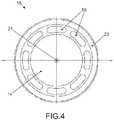
- a circular back plate 15, shown in a top view in figure 4 is realized with ceramic material as a ceramic plate.
- Back plate 15 comprises several holes 16 arranged on a diameter to enable air flow from an air gap 17 between the diaphragm 7 and the back plate 15 to a back volume 18 realized between the back plate 15 and the basis ceramic plate 10.
- a housing element realized as holding ring 19 holds the circular back plate 15 in a distance 20 to build sidewalls of back volume 18.
- Back plate 15 furthermore comprises a contact hole 21 in the center that is filled with a conductive glue 22 that provides electrical contact between the conductive capacitor layer 14 and the processing circuit 8 on conductive surface layer 13.
- acoustic airwaves move diaphragm 7 what reduces and increases air gap 17 that builds a dielectricum for the capacitor with the conductive capacitor layer 14 as one of the capacitor plates.
- an electrical signal influenced by the particular acoustic airwaves is detected and processed by processing circuit 8.
- Microphone 1 comprises a spacer that spaces diaphragm 7 from the conductive capacitor layer 14 to define and fix the distance of the air gap 17.
- This spacer is realized by a second conductive layer, named conductive spacer layer 23, on the same surface of back plate 15, but a different surface area of back plate 15.
- the conductive capacitor layer 14 is isolated from the conductive spacer area 23 in the area of holes 16.
- the air gap 17 is realized in that way that the conductive spacer area 23 is thicker than the conductive capacitor layer 14.
- conductive layers on ceramic plates may be manufactured by known manufacturing technologies like etching in a cheap and precise way, it is easy and robust to manufacture microphone 1 with a defined air gap 17.
- Microphone 1 furthermore comprises a fixation element formed by a first fixation ring 24 and a second fixation ring 25.
- the first fixation ring 24 is arranged between holding ring 19 and the second fixation ring 25 and comprises a circular area 26 to smoothly hold diaphragm 7 between the first fixation ring 24 and the second fixation ring 25 to span it over the conductive spacer layer 23.
- the circular area 26 therefore is arranged slightly below the level of the conductive spacer layer 23.
- Holding ring 19 as part of the housing elements of microphone 1 comprises a venting channel 27 with part of it formed as spiral grove 28 to enable air ventilation from back volume 18 to an area 29 outside of the housing of microphone 1.
- Venting channel 27 must be narrow and long to avoid that sound waves travel through it and affect the sound captured with microphone 1. It is in particular advantageous to form part or all of the venting channel 27 as spiral grove 28 as this extends the lengths of the venting channel 27 and enables easy production in a way a screw is manufactured.
- part or all of the spiral groove 28 could be realized in the first fixation ring 24 with a flat surface of holding ring 19.
- Other forms similar to a spiral grove with the same technical effect to extend the length of a narrow venting channel 27 could be used as well.
- microphone 1 may be realized with a thickness of only 1 mm or even smaller like 0,9 mm or 0,8 mm.
- This small realization of the surface mountable condenser microphone 1 enables minor or even no turbulences caused by the microphone 1 what enables to achieve a higher accuracy of the physical parameters like sound or pressure measured by microphone 1.
- the spacer could be realized by two conductive layers above each other. Above a first conductive surface layer in the area of the spacer a second conductive surface could be added on top of this first surface layer to achieve projection and the air gap of the diaphragm.
- fixation ring In another embodiment of the invention only one fixation ring to fix the diaphragm between the fixation ring and the holding ring could be realized. In another embodiment with two fixation rings the first fixation ring could be used to hold the back plate and build sidewalls of the back volume.
- the back plate and the basis plate could be realized by another material similar to ceramic like print card material like flex print that enables to generate conductive layers on the surface.
- the back plate could be realized by any isolating material with sufficient stiffness.
- the spacer layer is realized by a non-conductive material like glass or soldering mask to build the spacer layer. Any kind of material or manufacturing process would be fine that enables to generate a very thin layer of material to space the conductive capacitor layer from the membrane.
- the spacer layer is realized by an elevation of the back plate as part of the back plate. This has the advantage that no separate layer needs to be added to the back plate to realize the spacer layer.
Landscapes
- Engineering & Computer Science (AREA)
- Physics & Mathematics (AREA)
- Acoustics & Sound (AREA)
- Signal Processing (AREA)
- Multimedia (AREA)
- Electrostatic, Electromagnetic, Magneto- Strictive, And Variable-Resistance Transducers (AREA)
Priority Applications (7)
| Application Number | Priority Date | Filing Date | Title |
|---|---|---|---|
| PL17159485T PL3373597T3 (pl) | 2017-03-07 | 2017-03-07 | Mikrofon niskoprofilowy do montowania na powierzchni |
| EP17159485.6A EP3373597B1 (fr) | 2017-03-07 | 2017-03-07 | Microphone à montage en surface à profil bas |
| DK17159485T DK3373597T3 (da) | 2017-03-07 | 2017-03-07 | Mikrofon til montering på en overflade med lav profil |
| KR1020197025394A KR20190121780A (ko) | 2017-03-07 | 2018-02-26 | 로우 프로파일의 표면 실장 마이크로폰 |
| JP2019548292A JP7071388B2 (ja) | 2017-03-07 | 2018-02-26 | 目立たない表面実装マイクロホン |
| PCT/EP2018/054616 WO2018162263A1 (fr) | 2017-03-07 | 2018-02-26 | Microphone à montage en surface discret |
| US16/492,052 US11297440B2 (en) | 2017-03-07 | 2018-02-26 | Low profile surface mount microphone |
Applications Claiming Priority (1)
| Application Number | Priority Date | Filing Date | Title |
|---|---|---|---|
| EP17159485.6A EP3373597B1 (fr) | 2017-03-07 | 2017-03-07 | Microphone à montage en surface à profil bas |
Publications (2)
| Publication Number | Publication Date |
|---|---|
| EP3373597A1 true EP3373597A1 (fr) | 2018-09-12 |
| EP3373597B1 EP3373597B1 (fr) | 2019-08-14 |
Family
ID=58261553
Family Applications (1)
| Application Number | Title | Priority Date | Filing Date |
|---|---|---|---|
| EP17159485.6A Active EP3373597B1 (fr) | 2017-03-07 | 2017-03-07 | Microphone à montage en surface à profil bas |
Country Status (7)
| Country | Link |
|---|---|
| US (1) | US11297440B2 (fr) |
| EP (1) | EP3373597B1 (fr) |
| JP (1) | JP7071388B2 (fr) |
| KR (1) | KR20190121780A (fr) |
| DK (1) | DK3373597T3 (fr) |
| PL (1) | PL3373597T3 (fr) |
| WO (1) | WO2018162263A1 (fr) |
Families Citing this family (1)
| Publication number | Priority date | Publication date | Assignee | Title |
|---|---|---|---|---|
| CN211531325U (zh) * | 2020-02-25 | 2020-09-18 | 瑞声科技(新加坡)有限公司 | 一种扬声器及终端设备 |
Citations (5)
| Publication number | Priority date | Publication date | Assignee | Title |
|---|---|---|---|---|
| WO2004080122A1 (fr) * | 2003-03-04 | 2004-09-16 | Knowles Electronics, Llc | Microphone a condensateur electret |
| WO2007024047A1 (fr) * | 2005-08-20 | 2007-03-01 | Bse Co., Ltd | Microphone a condensateur electret |
| US20110192212A1 (en) | 2008-10-10 | 2011-08-11 | Eneria | System and method of counting and analyzing animal impacts on a wind turbine blade |
| EP1649718B1 (fr) | 2003-07-29 | 2012-07-25 | BSE Co., Ltd. | Microphone a condensateur electret montable en surface |
| US20130094676A1 (en) * | 2011-10-18 | 2013-04-18 | Hosiden Corporation | Electret Condenser Microphone |
Family Cites Families (8)
| Publication number | Priority date | Publication date | Assignee | Title |
|---|---|---|---|---|
| JP2578773Y2 (ja) * | 1993-06-25 | 1998-08-13 | ホシデン株式会社 | エレクトレットマイクロホン |
| US5854846A (en) * | 1996-09-06 | 1998-12-29 | Northrop Grumman Corporation | Wafer fabricated electroacoustic transducer |
| JP3835739B2 (ja) * | 2001-10-09 | 2006-10-18 | シチズン電子株式会社 | エレクトレットコンデンサマイクロフォン |
| US7224812B2 (en) * | 2004-01-13 | 2007-05-29 | Taiwan Carol Electronics Co., Ltd. | Condenser microphone and method for making the same |
| JP4751057B2 (ja) * | 2004-12-15 | 2011-08-17 | シチズン電子株式会社 | コンデンサマイクロホンとその製造方法 |
| SG131039A1 (en) * | 2005-09-14 | 2007-04-26 | Bse Co Ltd | Condenser microphone and packaging method for the same |
| KR100722686B1 (ko) * | 2006-05-09 | 2007-05-30 | 주식회사 비에스이 | 부가적인 백 챔버를 갖고 기판에 음향홀이 형성된 실리콘콘덴서 마이크로폰 |
| JP4960921B2 (ja) * | 2008-04-25 | 2012-06-27 | ホシデン株式会社 | エレクトレットコンデンサマイクロホン |
-
2017
- 2017-03-07 PL PL17159485T patent/PL3373597T3/pl unknown
- 2017-03-07 DK DK17159485T patent/DK3373597T3/da active
- 2017-03-07 EP EP17159485.6A patent/EP3373597B1/fr active Active
-
2018
- 2018-02-26 JP JP2019548292A patent/JP7071388B2/ja active Active
- 2018-02-26 KR KR1020197025394A patent/KR20190121780A/ko not_active Withdrawn
- 2018-02-26 US US16/492,052 patent/US11297440B2/en active Active
- 2018-02-26 WO PCT/EP2018/054616 patent/WO2018162263A1/fr not_active Ceased
Patent Citations (5)
| Publication number | Priority date | Publication date | Assignee | Title |
|---|---|---|---|---|
| WO2004080122A1 (fr) * | 2003-03-04 | 2004-09-16 | Knowles Electronics, Llc | Microphone a condensateur electret |
| EP1649718B1 (fr) | 2003-07-29 | 2012-07-25 | BSE Co., Ltd. | Microphone a condensateur electret montable en surface |
| WO2007024047A1 (fr) * | 2005-08-20 | 2007-03-01 | Bse Co., Ltd | Microphone a condensateur electret |
| US20110192212A1 (en) | 2008-10-10 | 2011-08-11 | Eneria | System and method of counting and analyzing animal impacts on a wind turbine blade |
| US20130094676A1 (en) * | 2011-10-18 | 2013-04-18 | Hosiden Corporation | Electret Condenser Microphone |
Also Published As
| Publication number | Publication date |
|---|---|
| US11297440B2 (en) | 2022-04-05 |
| JP2020509709A (ja) | 2020-03-26 |
| US20210144484A1 (en) | 2021-05-13 |
| DK3373597T3 (da) | 2019-10-28 |
| KR20190121780A (ko) | 2019-10-28 |
| EP3373597B1 (fr) | 2019-08-14 |
| PL3373597T3 (pl) | 2020-02-28 |
| JP7071388B2 (ja) | 2022-05-18 |
| WO2018162263A1 (fr) | 2018-09-13 |
Similar Documents
| Publication | Publication Date | Title |
|---|---|---|
| US11968487B2 (en) | Adapters for microphones and combinations thereof | |
| US7136500B2 (en) | Electret condenser microphone | |
| US20150189446A1 (en) | Silicon Condenser Microphone | |
| US20200255284A1 (en) | Acoustic relief in mems | |
| US11317184B2 (en) | Vibration sensor and audio device | |
| JP2005192178A (ja) | 統合ベース及びこれを利用したエレクトレットコンデンサマイクロホン | |
| EP2223534B1 (fr) | Microphone mems | |
| CN201197187Y (zh) | 形成有空气槽的振动板以及利用该振动板的电容麦克风 | |
| JP5620326B2 (ja) | コンデンサマイクロホンユニットおよびコンデンサマイクロホン | |
| CN102783182A (zh) | 电声换能器 | |
| US20150189443A1 (en) | Silicon Condenser Microphone | |
| US7233675B2 (en) | Method of forming an electret condenser microphone | |
| CN114520947A (zh) | 一种麦克风组件及电子设备 | |
| US11665485B2 (en) | Micro-electro-mechanical system acoustic sensor, micro-electro-mechanical system package structure and method for manufacturing the same | |
| EP3373597B1 (fr) | Microphone à montage en surface à profil bas | |
| US7835532B2 (en) | Microphone array | |
| CN104782144A (zh) | 双模片动态麦克风换能器 | |
| US11780726B2 (en) | Dual-diaphragm assembly having center constraint | |
| JP2006033215A (ja) | コンデンサマイクロホンとその製造方法 | |
| JP6224774B1 (ja) | 計測用マイクロホンモジュール | |
| CN1481654A (zh) | 电容性换能器 | |
| CN117177156A (zh) | 双振膜mems声音感测芯片 | |
| JP2006332799A (ja) | 音響センサ | |
| KR100537435B1 (ko) | 지향성 마이크로폰 | |
| CN110166914A (zh) | 硅麦克风 |
Legal Events
| Date | Code | Title | Description |
|---|---|---|---|
| STAA | Information on the status of an ep patent application or granted ep patent |
Free format text: STATUS: EXAMINATION IS IN PROGRESS |
|
| PUAI | Public reference made under article 153(3) epc to a published international application that has entered the european phase |
Free format text: ORIGINAL CODE: 0009012 |
|
| 17P | Request for examination filed |
Effective date: 20180226 |
|
| AK | Designated contracting states |
Kind code of ref document: A1 Designated state(s): AL AT BE BG CH CY CZ DE DK EE ES FI FR GB GR HR HU IE IS IT LI LT LU LV MC MK MT NL NO PL PT RO RS SE SI SK SM TR |
|
| AX | Request for extension of the european patent |
Extension state: BA ME |
|
| GRAP | Despatch of communication of intention to grant a patent |
Free format text: ORIGINAL CODE: EPIDOSNIGR1 |
|
| STAA | Information on the status of an ep patent application or granted ep patent |
Free format text: STATUS: GRANT OF PATENT IS INTENDED |
|
| INTG | Intention to grant announced |
Effective date: 20190325 |
|
| RIN1 | Information on inventor provided before grant (corrected) |
Inventor name: MEHR, ULRIK Inventor name: BOVIN, JONAS KABELL Inventor name: MARBJERG, KRESTEN |
|
| GRAS | Grant fee paid |
Free format text: ORIGINAL CODE: EPIDOSNIGR3 |
|
| GRAA | (expected) grant |
Free format text: ORIGINAL CODE: 0009210 |
|
| STAA | Information on the status of an ep patent application or granted ep patent |
Free format text: STATUS: THE PATENT HAS BEEN GRANTED |
|
| AK | Designated contracting states |
Kind code of ref document: B1 Designated state(s): AL AT BE BG CH CY CZ DE DK EE ES FI FR GB GR HR HU IE IS IT LI LT LU LV MC MK MT NL NO PL PT RO RS SE SI SK SM TR |
|
| REG | Reference to a national code |
Ref country code: GB Ref legal event code: FG4D |
|
| REG | Reference to a national code |
Ref country code: AT Ref legal event code: REF Ref document number: 1168466 Country of ref document: AT Kind code of ref document: T Effective date: 20190815 Ref country code: CH Ref legal event code: EP |
|
| REG | Reference to a national code |
Ref country code: IE Ref legal event code: FG4D |
|
| REG | Reference to a national code |
Ref country code: DE Ref legal event code: R096 Ref document number: 602017006009 Country of ref document: DE |
|
| REG | Reference to a national code |
Ref country code: DK Ref legal event code: T3 Effective date: 20191024 |
|
| REG | Reference to a national code |
Ref country code: NL Ref legal event code: MP Effective date: 20190814 |
|
| REG | Reference to a national code |
Ref country code: LT Ref legal event code: MG4D |
|
| PG25 | Lapsed in a contracting state [announced via postgrant information from national office to epo] |
Ref country code: NO Free format text: LAPSE BECAUSE OF FAILURE TO SUBMIT A TRANSLATION OF THE DESCRIPTION OR TO PAY THE FEE WITHIN THE PRESCRIBED TIME-LIMIT Effective date: 20191114 Ref country code: FI Free format text: LAPSE BECAUSE OF FAILURE TO SUBMIT A TRANSLATION OF THE DESCRIPTION OR TO PAY THE FEE WITHIN THE PRESCRIBED TIME-LIMIT Effective date: 20190814 Ref country code: PT Free format text: LAPSE BECAUSE OF FAILURE TO SUBMIT A TRANSLATION OF THE DESCRIPTION OR TO PAY THE FEE WITHIN THE PRESCRIBED TIME-LIMIT Effective date: 20191216 Ref country code: NL Free format text: LAPSE BECAUSE OF FAILURE TO SUBMIT A TRANSLATION OF THE DESCRIPTION OR TO PAY THE FEE WITHIN THE PRESCRIBED TIME-LIMIT Effective date: 20190814 Ref country code: SE Free format text: LAPSE BECAUSE OF FAILURE TO SUBMIT A TRANSLATION OF THE DESCRIPTION OR TO PAY THE FEE WITHIN THE PRESCRIBED TIME-LIMIT Effective date: 20190814 Ref country code: BG Free format text: LAPSE BECAUSE OF FAILURE TO SUBMIT A TRANSLATION OF THE DESCRIPTION OR TO PAY THE FEE WITHIN THE PRESCRIBED TIME-LIMIT Effective date: 20191114 Ref country code: LT Free format text: LAPSE BECAUSE OF FAILURE TO SUBMIT A TRANSLATION OF THE DESCRIPTION OR TO PAY THE FEE WITHIN THE PRESCRIBED TIME-LIMIT Effective date: 20190814 Ref country code: HR Free format text: LAPSE BECAUSE OF FAILURE TO SUBMIT A TRANSLATION OF THE DESCRIPTION OR TO PAY THE FEE WITHIN THE PRESCRIBED TIME-LIMIT Effective date: 20190814 |
|
| REG | Reference to a national code |
Ref country code: AT Ref legal event code: MK05 Ref document number: 1168466 Country of ref document: AT Kind code of ref document: T Effective date: 20190814 |
|
| PG25 | Lapsed in a contracting state [announced via postgrant information from national office to epo] |
Ref country code: GR Free format text: LAPSE BECAUSE OF FAILURE TO SUBMIT A TRANSLATION OF THE DESCRIPTION OR TO PAY THE FEE WITHIN THE PRESCRIBED TIME-LIMIT Effective date: 20191115 Ref country code: AL Free format text: LAPSE BECAUSE OF FAILURE TO SUBMIT A TRANSLATION OF THE DESCRIPTION OR TO PAY THE FEE WITHIN THE PRESCRIBED TIME-LIMIT Effective date: 20190814 Ref country code: ES Free format text: LAPSE BECAUSE OF FAILURE TO SUBMIT A TRANSLATION OF THE DESCRIPTION OR TO PAY THE FEE WITHIN THE PRESCRIBED TIME-LIMIT Effective date: 20190814 Ref country code: LV Free format text: LAPSE BECAUSE OF FAILURE TO SUBMIT A TRANSLATION OF THE DESCRIPTION OR TO PAY THE FEE WITHIN THE PRESCRIBED TIME-LIMIT Effective date: 20190814 Ref country code: RS Free format text: LAPSE BECAUSE OF FAILURE TO SUBMIT A TRANSLATION OF THE DESCRIPTION OR TO PAY THE FEE WITHIN THE PRESCRIBED TIME-LIMIT Effective date: 20190814 Ref country code: IS Free format text: LAPSE BECAUSE OF FAILURE TO SUBMIT A TRANSLATION OF THE DESCRIPTION OR TO PAY THE FEE WITHIN THE PRESCRIBED TIME-LIMIT Effective date: 20191214 |
|
| PG25 | Lapsed in a contracting state [announced via postgrant information from national office to epo] |
Ref country code: TR Free format text: LAPSE BECAUSE OF FAILURE TO SUBMIT A TRANSLATION OF THE DESCRIPTION OR TO PAY THE FEE WITHIN THE PRESCRIBED TIME-LIMIT Effective date: 20190814 |
|
| PG25 | Lapsed in a contracting state [announced via postgrant information from national office to epo] |
Ref country code: IT Free format text: LAPSE BECAUSE OF FAILURE TO SUBMIT A TRANSLATION OF THE DESCRIPTION OR TO PAY THE FEE WITHIN THE PRESCRIBED TIME-LIMIT Effective date: 20190814 Ref country code: RO Free format text: LAPSE BECAUSE OF FAILURE TO SUBMIT A TRANSLATION OF THE DESCRIPTION OR TO PAY THE FEE WITHIN THE PRESCRIBED TIME-LIMIT Effective date: 20190814 Ref country code: EE Free format text: LAPSE BECAUSE OF FAILURE TO SUBMIT A TRANSLATION OF THE DESCRIPTION OR TO PAY THE FEE WITHIN THE PRESCRIBED TIME-LIMIT Effective date: 20190814 Ref country code: AT Free format text: LAPSE BECAUSE OF FAILURE TO SUBMIT A TRANSLATION OF THE DESCRIPTION OR TO PAY THE FEE WITHIN THE PRESCRIBED TIME-LIMIT Effective date: 20190814 |
|
| PG25 | Lapsed in a contracting state [announced via postgrant information from national office to epo] |
Ref country code: CZ Free format text: LAPSE BECAUSE OF FAILURE TO SUBMIT A TRANSLATION OF THE DESCRIPTION OR TO PAY THE FEE WITHIN THE PRESCRIBED TIME-LIMIT Effective date: 20190814 Ref country code: IS Free format text: LAPSE BECAUSE OF FAILURE TO SUBMIT A TRANSLATION OF THE DESCRIPTION OR TO PAY THE FEE WITHIN THE PRESCRIBED TIME-LIMIT Effective date: 20200224 Ref country code: SK Free format text: LAPSE BECAUSE OF FAILURE TO SUBMIT A TRANSLATION OF THE DESCRIPTION OR TO PAY THE FEE WITHIN THE PRESCRIBED TIME-LIMIT Effective date: 20190814 Ref country code: SM Free format text: LAPSE BECAUSE OF FAILURE TO SUBMIT A TRANSLATION OF THE DESCRIPTION OR TO PAY THE FEE WITHIN THE PRESCRIBED TIME-LIMIT Effective date: 20190814 |
|
| REG | Reference to a national code |
Ref country code: DE Ref legal event code: R097 Ref document number: 602017006009 Country of ref document: DE |
|
| PLBE | No opposition filed within time limit |
Free format text: ORIGINAL CODE: 0009261 |
|
| STAA | Information on the status of an ep patent application or granted ep patent |
Free format text: STATUS: NO OPPOSITION FILED WITHIN TIME LIMIT |
|
| PG2D | Information on lapse in contracting state deleted |
Ref country code: IS |
|
| 26N | No opposition filed |
Effective date: 20200603 |
|
| PG25 | Lapsed in a contracting state [announced via postgrant information from national office to epo] |
Ref country code: SI Free format text: LAPSE BECAUSE OF FAILURE TO SUBMIT A TRANSLATION OF THE DESCRIPTION OR TO PAY THE FEE WITHIN THE PRESCRIBED TIME-LIMIT Effective date: 20190814 |
|
| PG25 | Lapsed in a contracting state [announced via postgrant information from national office to epo] |
Ref country code: MC Free format text: LAPSE BECAUSE OF FAILURE TO SUBMIT A TRANSLATION OF THE DESCRIPTION OR TO PAY THE FEE WITHIN THE PRESCRIBED TIME-LIMIT Effective date: 20190814 |
|
| REG | Reference to a national code |
Ref country code: CH Ref legal event code: PL |
|
| REG | Reference to a national code |
Ref country code: BE Ref legal event code: MM Effective date: 20200331 |
|
| PG25 | Lapsed in a contracting state [announced via postgrant information from national office to epo] |
Ref country code: LU Free format text: LAPSE BECAUSE OF NON-PAYMENT OF DUE FEES Effective date: 20200307 |
|
| PG25 | Lapsed in a contracting state [announced via postgrant information from national office to epo] |
Ref country code: IE Free format text: LAPSE BECAUSE OF NON-PAYMENT OF DUE FEES Effective date: 20200307 Ref country code: CH Free format text: LAPSE BECAUSE OF NON-PAYMENT OF DUE FEES Effective date: 20200331 Ref country code: LI Free format text: LAPSE BECAUSE OF NON-PAYMENT OF DUE FEES Effective date: 20200331 |
|
| PG25 | Lapsed in a contracting state [announced via postgrant information from national office to epo] |
Ref country code: BE Free format text: LAPSE BECAUSE OF NON-PAYMENT OF DUE FEES Effective date: 20200331 |
|
| PG25 | Lapsed in a contracting state [announced via postgrant information from national office to epo] |
Ref country code: MT Free format text: LAPSE BECAUSE OF FAILURE TO SUBMIT A TRANSLATION OF THE DESCRIPTION OR TO PAY THE FEE WITHIN THE PRESCRIBED TIME-LIMIT Effective date: 20190814 Ref country code: CY Free format text: LAPSE BECAUSE OF FAILURE TO SUBMIT A TRANSLATION OF THE DESCRIPTION OR TO PAY THE FEE WITHIN THE PRESCRIBED TIME-LIMIT Effective date: 20190814 |
|
| PG25 | Lapsed in a contracting state [announced via postgrant information from national office to epo] |
Ref country code: MK Free format text: LAPSE BECAUSE OF FAILURE TO SUBMIT A TRANSLATION OF THE DESCRIPTION OR TO PAY THE FEE WITHIN THE PRESCRIBED TIME-LIMIT Effective date: 20190814 |
|
| PGFP | Annual fee paid to national office [announced via postgrant information from national office to epo] |
Ref country code: GB Payment date: 20260324 Year of fee payment: 10 |
|
| PGFP | Annual fee paid to national office [announced via postgrant information from national office to epo] |
Ref country code: DE Payment date: 20260320 Year of fee payment: 10 Ref country code: DK Payment date: 20260323 Year of fee payment: 10 |
|
| PGFP | Annual fee paid to national office [announced via postgrant information from national office to epo] |
Ref country code: FR Payment date: 20260325 Year of fee payment: 10 |
|
| PGFP | Annual fee paid to national office [announced via postgrant information from national office to epo] |
Ref country code: PL Payment date: 20260225 Year of fee payment: 10 |