EP3374018B1 - Clamp pour tuyau flexible pour un appareil de traitement du sang - Google Patents
Clamp pour tuyau flexible pour un appareil de traitement du sang Download PDFInfo
- Publication number
- EP3374018B1 EP3374018B1 EP16798403.8A EP16798403A EP3374018B1 EP 3374018 B1 EP3374018 B1 EP 3374018B1 EP 16798403 A EP16798403 A EP 16798403A EP 3374018 B1 EP3374018 B1 EP 3374018B1
- Authority
- EP
- European Patent Office
- Prior art keywords
- hose
- hose clamp
- compression piece
- accordance
- guideway
- Prior art date
- Legal status (The legal status is an assumption and is not a legal conclusion. Google has not performed a legal analysis and makes no representation as to the accuracy of the status listed.)
- Active
Links
Images

Classifications
-
- A—HUMAN NECESSITIES
- A61—MEDICAL OR VETERINARY SCIENCE; HYGIENE
- A61M—DEVICES FOR INTRODUCING MEDIA INTO, OR ONTO, THE BODY; DEVICES FOR TRANSDUCING BODY MEDIA OR FOR TAKING MEDIA FROM THE BODY; DEVICES FOR PRODUCING OR ENDING SLEEP OR STUPOR
- A61M39/00—Tubes, tube connectors, tube couplings, valves, access sites or the like, specially adapted for medical use
- A61M39/22—Valves or arrangement of valves
- A61M39/28—Clamping means for squeezing flexible tubes, e.g. roller clamps
- A61M39/284—Lever clamps
-
- A—HUMAN NECESSITIES
- A61—MEDICAL OR VETERINARY SCIENCE; HYGIENE
- A61M—DEVICES FOR INTRODUCING MEDIA INTO, OR ONTO, THE BODY; DEVICES FOR TRANSDUCING BODY MEDIA OR FOR TAKING MEDIA FROM THE BODY; DEVICES FOR PRODUCING OR ENDING SLEEP OR STUPOR
- A61M1/00—Suction or pumping devices for medical purposes; Devices for carrying-off, for treatment of, or for carrying-over, body-liquids; Drainage systems
- A61M1/36—Other treatment of blood in a by-pass of the natural circulatory system, e.g. temperature adaptation, irradiation ; Extra-corporeal blood circuits
- A61M1/3621—Extra-corporeal blood circuits
- A61M1/367—Circuit parts not covered by the preceding subgroups of group A61M1/3621
-
- A—HUMAN NECESSITIES
- A61—MEDICAL OR VETERINARY SCIENCE; HYGIENE
- A61M—DEVICES FOR INTRODUCING MEDIA INTO, OR ONTO, THE BODY; DEVICES FOR TRANSDUCING BODY MEDIA OR FOR TAKING MEDIA FROM THE BODY; DEVICES FOR PRODUCING OR ENDING SLEEP OR STUPOR
- A61M39/00—Tubes, tube connectors, tube couplings, valves, access sites or the like, specially adapted for medical use
- A61M39/22—Valves or arrangement of valves
- A61M39/28—Clamping means for squeezing flexible tubes, e.g. roller clamps
- A61M39/281—Automatic tube cut-off devices, e.g. squeezing tube on detection of air
-
- A—HUMAN NECESSITIES
- A61—MEDICAL OR VETERINARY SCIENCE; HYGIENE
- A61M—DEVICES FOR INTRODUCING MEDIA INTO, OR ONTO, THE BODY; DEVICES FOR TRANSDUCING BODY MEDIA OR FOR TAKING MEDIA FROM THE BODY; DEVICES FOR PRODUCING OR ENDING SLEEP OR STUPOR
- A61M5/00—Devices for bringing media into the body in a subcutaneous, intra-vascular or intramuscular way; Accessories therefor, e.g. filling or cleaning devices, arm-rests
- A61M5/14—Infusion devices, e.g. infusing by gravity; Blood infusion; Accessories therefor
- A61M5/168—Means for controlling media flow to the body or for metering media to the body, e.g. drip meters, counters ; Monitoring media flow to the body
- A61M5/16804—Flow controllers
- A61M5/16813—Flow controllers by controlling the degree of opening of the flow line
Definitions
- the invention relates to a hose clamp for a blood treatment device, a blood treatment device with such a hose clamp and a method for removing or inserting a hose set from or into such a blood treatment device.
- blood treatment devices have a hose clamp that is used to clamp a hose of the extracorporeal blood circuit.
- the clamp enables the patient to be separated from the extracorporeal blood circulation in the course of the treatment, in particular in order to avoid blood loss.
- the devices are prepared for the following day after the last treatment in the evening and the tubing set serving as extracorporeal blood circulation is inserted.
- the clamp Since the device is regularly de-energized overnight, the clamp regularly clamps the hose over a longer period of time. This leads to permanent squeezing of the hose, which is irreversibly deformed in the affected area as a result. This can lead to undesirable turbulence during operation.
- the document discloses US2010 / 057016A1 a hose clamp that remains in the closed position in the event of a power failure.
- the aim of the invention is to avoid this disadvantage.
- the invention relates to a hose clamp for a blood treatment device, which has a housing and an electromechanically driven pressure piece.
- the electromechanical drive of the pressure piece is designed in such a way that it is opened against a mechanical restoring force when the hose clamp is energized and is closed by the mechanical restoring force when the hose clamp is de-energized.
- the hose clamp has a mechanical actuator with which the pressure piece can be opened manually against the mechanical restoring force when the hose clamp is de-energized.
- the contact elements of the actuator and the pressure piece are designed so that after opening the pressure piece in the de-energized state, they form a mechanical connection between the actuator and the pressure piece, which allows the pressure piece to be closed again in the de-energized state of the hose clamp mechanical restoring force prevented, and which is released when the hose clamp is energized.
- One contact element preferably the contact element on the pressure piece side
- the other contact element preferably the actuator-side contact element
- the guide track is designed in such a way that the projection moves along it when the actuator is actuated.
- the guideway also includes at a saddle point at which the projection is in an open position of the pressure piece, a latching contour for the projection.
- the guide track can be, for example, an edge of the actuator or a link guide in the actuator or in the pressure piece.
- the actuator is a pivotable lever, the guide track preferably being arranged on a side edge of the lever arm.
- the guide track is at least partially convex and preferably partially circular.
- the stop contour is preferably located beyond the saddle point.
- the stop contour limits the maximum opening of the pressure piece that can be reached by the actuator.
- the stop contour can be a linear section of the guideway that has a different slope than the sections located in front of the saddle point.
- the projection is a pin, which is preferably perpendicular to the closing direction of the pressure piece.
- the pin can, for example, be rotatably mounted on the pressure piece or on the actuator so that it rolls along the guide track or can be fixedly mounted so that it slides along the guide track.
- the latching contour is a depression in the guideway and / or a step on the guideway.
- the recess can for example be a circular indentation in the guide track at the saddle point, wherein the radius of the circular indentation can for example correspond to the radius of the pin.
- the hose clamp has a mechanical spring connected to the actuator and the housing, preferably a mechanical tension spring, which exerts a restoring force on the actuator against its actuation direction when the pressure piece is opened.
- the invention also relates to a blood treatment device, preferably a dialysis machine with an extracorporeal blood circuit, which has a line section designed as a hose, the line section preferably forming part of the arterial or venous line of the extracorporeal blood circuit.
- a hose clamp according to the invention is arranged on the line section designed as a hose.
- the dialysis machine can be, for example, a machine for performing hemodialysis, hemodiafiltration and / or hemofiltration.
- the hose is preferably a hose made of plastic, which can, for example, have a round cross-section.
- the arterial line is in front of the flow direction and the venous line is after the treatment device of the device, for example the dialyzer of the dialysis machine.
- the clamp arranged on it is an arterial or a venous clamp.
- the line section and the clamp are preferably located near the arterial or venous port to which the patient is connected to the blood circulation.
- the extracorporeal blood circuit can of course have a plurality of line sections designed as a hose and the blood treatment device can of course have a plurality of identically or differently designed clamps which engage on one or more of these line sections. It is essential to the invention that at least one line section designed as a hose is present on which at least one clamp according to the invention is arranged.
- the extracorporeal blood circuit has two line sections designed as tubes, one of these line sections forming part of the arterial and the other of these line sections forming part of the venous line of the extracorporeal blood circuit.
- the blood treatment device has two hose clamps according to the invention, one of these hose clamps being arranged on one of these line sections and the other of the hose clamps being arranged on the other of these line sections.
- the invention relates to a method for removing or inserting a tube set from or into a blood treatment device according to the invention.
- the hose set forms at least part of the extracorporeal blood circuit and comprises the line section on which the hose clamp according to the invention is arranged.
- the pressure piece is opened in the de-energized state by actuating the actuator and the hose set is then removed or inserted from the hose clamp in the still de-energized state, while the pressure piece is kept open by the mechanical connection between the actuator and the pressure piece.
- removing and inserting the tubing set means exchanging the tubing set.
- the tubing set can be replaced or inserted the evening before, and the dialysis machine can still remain without power overnight without the tubing set being clamped and possibly deformed or damaged in the process.
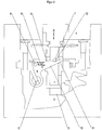
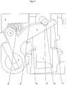
- Figures 1 and 2 show a previously known hose clamp of a dialysis machine from the prior art.
- the hose clamp comprises a movable pressure piece 1 and a stationary saddle 2. In between there is a recess 3 for receiving a plastic tube, for example a plastic tube, which forms a section of an extracorporeal blood circuit of a dialysis machine.
- the pressure piece 1 is mounted vertically displaceably within the clamp housing 4 (directions or positions such as “vertical”, “horizontal”, “top”, “bottom” etc. relate to the illustration shown and not to the actual installation position of the tube clamp in the blood treatment device) .
- the vertical displacement of the pressure piece is controlled by means of an electromechanical system not shown in detail in the figures.
- This electromechanical system includes, on the one hand, a mechanical compression spring which pushes the pressure piece 1 downwards (direction A) into the position shown in FIG Figure 1 shown closed position presses.
- the electromechanical system also includes an electromagnet which pulls the pressure piece 1 upwards (direction B) in the energized state against the restoring force of the mechanical compression spring.
- the opening force caused by the electromagnet is greater than that of the mechanical one Compression spring produced closing force.
- the open state of the terminal when the electromagnet is energized is not shown in the figures.
- a pivotable lever 5 In addition to lifting the pressure piece 1 by energizing the electromagnet, manual lifting of the pressure piece 1 by actuating a pivotable lever 5 is also possible.
- the lever 5 reaches through an opening in the pressure piece 1 and comprises a guide track 6 which interacts with a pin 7 which is integrally formed on or attached to the pressure piece 1.
- the lever 5 can be moved from a horizontal rest position ( Figure 1 ) to a raised position ( Figure 2 ) can be swiveled.
- the mechanical counterforce is exerted on the one hand by the tension spring 8, which is arranged between the terminal housing 4 and an extension 9 of the lever 5, and on the other hand by the restoring force that acts on the pressure piece 1 and based on the contact elements 6 and 7 on the Lever 5 is passed.
- the actuating element seated in the extension of the axis C for manually pivoting the lever which can be, for example, a rotary knob or a handle lever, is not shown in detail in the figures and is covered by the housing 4.
- the guide track 6 comprises a convex bulge on the upper side of the lever arm 10 as well as a straight end region 11 running parallel to the direction of the lever arm.
- the saddle point 12 is located between the convex bulge and the straight section.
- the lever 5 In the currentless initial state of the hose clamp according to Figure 1 the lever 5 is in its rest state. If, in this state, a hose is to be removed from the receptacle 3 or a hose is to be inserted into the receptacle 3, the pressure piece 1 can be raised by actuating the lever. In the starting position, the lever 5 is held in a horizontal position by the tension spring 8. The pin 7 of the pressure piece 1 rests approximately in the middle of the convex guide track 6. Starting from this position, the lever 5 is manually operated When the actuation is pivoted upwards, the pin 7 resting on the guide track 6 and thus the pressure piece 1 are raised against the mechanical spring force A. The maximum amplitude of this mechanical lifting or opening of the clamp is reached when the pin has reached the saddle point 12 of the lever 5 and further lifting is no longer possible due to the abrupt change in the slope of the guideway 6.
- the lever 5 thus has no influence on the mechanical closing of the terminal in the de-energized state when it is not being actuated.
- FIG Figure 3 shows a sectional view of a hose clamp according to the invention in the de-energized and manually opened state, as shown in FIG Figure 2 for the hose clamp from the prior art is shown.
- a latching contour in the form of a recess 13 in the guide track 6 is arranged according to the invention at the saddle point 12 of the lever 5.
- the recess 13 is part-circular, the radius of the part-circle corresponding to the outer radius of the pin 7.
- the hose clamp remains open after the clamp has been mechanically opened in the de-energized state.
- the inventive idea consists in providing the hose clamp with a holding and, in particular, latching function, which can be activated manually in the evening, for example, so that the hose of the extracorporeal blood circuit is not clamped overnight despite the lack of power.
- the latching function can be deactivated when the device is started the next day.
- the clamp can then clamp the tube when the dialysis machine is de-energized, as is known from the prior art.
Landscapes
- Health & Medical Sciences (AREA)
- Heart & Thoracic Surgery (AREA)
- Animal Behavior & Ethology (AREA)
- General Health & Medical Sciences (AREA)
- Anesthesiology (AREA)
- Biomedical Technology (AREA)
- Hematology (AREA)
- Life Sciences & Earth Sciences (AREA)
- Veterinary Medicine (AREA)
- Engineering & Computer Science (AREA)
- Public Health (AREA)
- Vascular Medicine (AREA)
- Pulmonology (AREA)
- Cardiology (AREA)
- External Artificial Organs (AREA)
- Infusion, Injection, And Reservoir Apparatuses (AREA)
Claims (10)
- Clamp pour tuyau flexible pour un appareil de traitement du sang, dans lequel le clamp pour tuyau flexible présente un boîtier (4) et une pièce de pression (1) entraînée de manière électromécanique, dans lequel
l'entraînement électromécanique de la pièce de pression (1) est réalisé de telle manière que la pièce de pression (1) est ouverte dans un état alimenté en courant du clamp pour tuyau flexible à l'encontre d'une force de rappel (A) mécanique et est fermée dans un état sans courant du clamp pour tuyau flexible par la force de rappel (A) mécanique, et
le clamp pour tuyau flexible présente en plus de l'entraînement électromécanique un levier (5) pouvant pivoter, avec lequel la pièce de pression (1) peut être ouverte manuellement à l'encontre de la force de rappel (A) mécanique dans l'état sans courant du clamp pour tuyau flexible,
caractérisé en ce que
les éléments de contact (6, 7) du levier (5) et de la pièce de pression (1) sont une partie faisant saillie (7) et une voie de guidage (6) qui sont réalisées de telle sorte qu'elles réalisent, après une ouverture de la pièce de pression (1), dans l'état sans courant, une liaison mécanique entre le levier (5) et la pièce de pression (1), dans lequel
la liaison mécanique présente un contour d'enclenchement (13) de la voie de guidage pour enclencher la partie faisant saillie (7) avec le levier (5), qui empêche une nouvelle fermeture de la pièce de pression (1) dans l'état sans courant du clamp pour tuyau flexible, du fait de la force de rappel (A) mécanique et qui est desserré dans l'état alimenté en courant du clamp pour tuyau flexible dans la mesure où la pièce de pression (1) est relevée en supplément dans l'état alimenté en courant, ce qui permet de desserrer la liaison par enclenchement,
et dans lequel la voie de guidage (6) présente, sur un point de col (12), sur lequel se trouve la partie faisant saillie (7) dans une position ouverte de la pièce de pression (1), le contour d'enclenchement (13) pour la partie faisant saillie (7). - Clamp pour tuyau flexible selon la revendication 1, dans lequel l'élément de contact côté pièce de pression (7) est la partie faisant saillie (7) et l'élément de contact côté actionneur (6) est la voie de guidage (6), dans lequel la voie de guidage (6) est réalisée de telle sorte que la partie faisant saillie (7) se déplace lors de l'actionnement de l'actionneur (5) le long de celui-ci.
- Clamp pour tuyau flexible selon l'une quelconque des revendications précédentes, dans lequel la voie de guidage (6) est disposée sur une arête latérale du bras de levier (10).
- Clamp pour tuyau flexible selon la revendication 2 ou 3, dans lequel la voie de guidage (6) est réalisée au moins par endroits de manière convexe et de préférence en forme de cercle partiel.
- Clamp pour tuyau flexible selon l'une quelconque des revendications 2 à 4, dans lequel la partie faisant saillie (7) est une tige (7), qui se dresse de préférence de manière normale sur la direction de fermeture (A) de la pièce de pression (1).
- Clamp pour tuyau flexible selon l'une quelconque des revendications 2 à 5, dans lequel le contour d'enclenchement (13) est un renfoncement (13) dans la voie de guidage (6) et/ou un palier sur la voie de guidage (6).
- Clamp pour tuyau flexible selon l'une quelconque des revendications précédentes, dans lequel le clamp pour tuyau flexible comprend un ressort (8) mécanique relié au levier (5) et au boîtier (4) et de préférence un ressort de traction (8), qui exerce une force de rappel (D) sur le levier (5) à l'encontre de son sens d'actionnement lors de l'ouverture de la pièce de pression (1).
- Appareil de traitement du sang, de préférence appareil de dialyse avec un circuit extracorporel de sang, qui présente un tronçon de conduit réalisé en tant que tuyau flexible, dans lequel
le tronçon de conduit réalise de préférence une partie du conduit artériel ou du conduit veineux du circuit extracorporel de sang,
dans lequel un clamp pour tuyau flexible selon l'une quelconque des revendications précédentes est disposé sur le tronçon de conduit réalisé en tant que tuyau flexible. - Appareil de traitement du sang selon la revendication 8, dans lequel le circuit extracorporel de sang présente deux tronçons de conduit réalisés en tant que tuyaux flexibles, dans lequel un desdits tronçons de conduit réalise une partie du conduit artériel et l'autre desdits tronçons de conduit réalise une partie du conduit veineux du circuit extracorporel de sang, et l'appareil de traitement du sang présente deux clamps pour tuyau flexible, dans lequel un desdits clamps pour tuyau flexible est disposé sur un desdits tronçons de conduit et l'autre des clamps pour tuyau flexible est disposé sur l'autre desdits tronçons de conduit, dans lequel les deux clamps pour tuyau flexible sont des clamps pour tuyau flexible selon l'une quelconque des revendications 1 à 7.
- Procédé pour retirer et/ou insérer un ensemble de tuyaux flexibles hors ou dans un appareil de traitement du sang selon l'une quelconque des revendications 8 ou 9, dans lequel l'ensemble de tuyaux flexibles réalise au moins une partie du circuit extracorporel de sang et comprend le tronçon de conduit, sur lequel le clamp pour tuyau flexible est disposé selon l'une quelconque des revendications 1 à 7,
caractérisé en ce que
la pièce de pression (1) est ouverte dans l'état sans courant par l'actionnement de l'actionneur (5) et l'ensemble de tuyaux flexibles est retiré ou inséré ensuite dans l'état par ailleurs sans courant du clamp pour tuyau flexible, tandis que la pièce de pression (1) est maintenue ouverte par la liaison mécanique entre l'actionneur (5) et la pièce de pression (1).
Applications Claiming Priority (2)
| Application Number | Priority Date | Filing Date | Title |
|---|---|---|---|
| DE102015014741.2A DE102015014741A1 (de) | 2015-11-13 | 2015-11-13 | Schlauchklemme für ein Blutbehandlungsgerät |
| PCT/EP2016/001879 WO2017080663A1 (fr) | 2015-11-13 | 2016-11-11 | Clamp pour tuyau flexible pour un appareil de traitement du sang |
Publications (2)
| Publication Number | Publication Date |
|---|---|
| EP3374018A1 EP3374018A1 (fr) | 2018-09-19 |
| EP3374018B1 true EP3374018B1 (fr) | 2021-08-18 |
Family
ID=57354317
Family Applications (1)
| Application Number | Title | Priority Date | Filing Date |
|---|---|---|---|
| EP16798403.8A Active EP3374018B1 (fr) | 2015-11-13 | 2016-11-11 | Clamp pour tuyau flexible pour un appareil de traitement du sang |
Country Status (6)
| Country | Link |
|---|---|
| US (1) | US10661071B2 (fr) |
| EP (1) | EP3374018B1 (fr) |
| JP (1) | JP6980653B2 (fr) |
| CN (1) | CN108348744B (fr) |
| DE (1) | DE102015014741A1 (fr) |
| WO (1) | WO2017080663A1 (fr) |
Families Citing this family (2)
| Publication number | Priority date | Publication date | Assignee | Title |
|---|---|---|---|---|
| DE102019110276A1 (de) * | 2019-04-18 | 2020-10-22 | Fresenius Medical Care AG & Co. KGaA | Blockiervorrichtung für eine Schlauchklemme einer Blutbehandlungsmaschine |
| CN112316245B (zh) * | 2020-10-30 | 2021-07-27 | 深圳市好克医疗仪器股份有限公司 | 手动止液机构以及止液设备 |
Family Cites Families (10)
| Publication number | Priority date | Publication date | Assignee | Title |
|---|---|---|---|---|
| US4061142A (en) * | 1976-06-16 | 1977-12-06 | Sandoz, Inc. | Apparatus for controlling blood flow |
| US5413566A (en) * | 1993-03-16 | 1995-05-09 | Micropump Corporation | Line clamp |
| IT1271099B (it) * | 1994-11-25 | 1997-05-26 | Francesco Bellifemine | Dispositivo per la sorveglianza ed il controllo di un impianto di fleboclisi migliorato |
| US8863772B2 (en) * | 2008-08-27 | 2014-10-21 | Deka Products Limited Partnership | Occluder for a medical infusion system |
| US7922700B2 (en) * | 2008-10-30 | 2011-04-12 | Acist Medical Systems, Inc. | Pinch valve mechanism for a medical fluid injection device |
| US9364655B2 (en) * | 2012-05-24 | 2016-06-14 | Deka Products Limited Partnership | Flexible tubing occlusion assembly |
| DE102012105926A1 (de) * | 2012-07-03 | 2014-01-09 | B. Braun Avitum Ag | Schlauchrollenpumpe mit schwenkbarer Schlauchaufnahme, und medizinisches Gerät für extrakorporale Blutbehandlung |
| JP6089757B2 (ja) * | 2013-02-18 | 2017-03-08 | 株式会社ジェイ・エム・エス | チューブクランプ装置 |
| DE102013008720B4 (de) * | 2013-05-23 | 2019-05-09 | Fresenius Medical Care Deutschland Gmbh | Verfahren und Vorrichtung zur Überwachung eines extrakorporalen Blutkreislaufs |
| CA2984341C (fr) * | 2015-05-04 | 2024-10-22 | Carefusion 303, Inc. | Vanne de tube de perfusion a fluide et systeme |
-
2015
- 2015-11-13 DE DE102015014741.2A patent/DE102015014741A1/de active Granted
-
2016
- 2016-11-11 US US15/775,949 patent/US10661071B2/en active Active
- 2016-11-11 JP JP2018524312A patent/JP6980653B2/ja active Active
- 2016-11-11 EP EP16798403.8A patent/EP3374018B1/fr active Active
- 2016-11-11 WO PCT/EP2016/001879 patent/WO2017080663A1/fr not_active Ceased
- 2016-11-11 CN CN201680066263.XA patent/CN108348744B/zh active Active
Non-Patent Citations (1)
| Title |
|---|
| None * |
Also Published As
| Publication number | Publication date |
|---|---|
| DE102015014741A1 (de) | 2017-05-18 |
| WO2017080663A1 (fr) | 2017-05-18 |
| EP3374018A1 (fr) | 2018-09-19 |
| JP2018533427A (ja) | 2018-11-15 |
| CN108348744B (zh) | 2021-01-26 |
| JP6980653B2 (ja) | 2021-12-15 |
| US20180353746A1 (en) | 2018-12-13 |
| CN108348744A (zh) | 2018-07-31 |
| US10661071B2 (en) | 2020-05-26 |
Similar Documents
| Publication | Publication Date | Title |
|---|---|---|
| DE69023301T2 (de) | Flüssigkeitsversorgungseinrichtung. | |
| DE69512464T2 (de) | Zweistufige Durchflusssperre für I.V. Flüssigkeit | |
| EP1218055B1 (fr) | Clamp pour tuyau flexible, pompe a perfusion, ensemble tuyau flexible de perfusion, et combinaison d'une pompe a perfusion et d'un ensemble tuyau flexible de perfusion | |
| DE69308366T2 (de) | Strömungsventil | |
| DE3728149C2 (fr) | ||
| EP2275681B1 (fr) | Pompe à rouleaux | |
| WO2013056868A1 (fr) | Pince pour tubulure de perfusion pour une pompe à perfusion et procede d'utilisation de cette pince | |
| DE102011011662A1 (de) | Türverschluss für eine Spülmaschine | |
| EP3651831B1 (fr) | Dispositif de commande de l'ouverture et de la fermeture d'un tuyau | |
| EP3374018B1 (fr) | Clamp pour tuyau flexible pour un appareil de traitement du sang | |
| EP3243485A1 (fr) | Dispositif de maintien d'anneau de suture | |
| WO2019097075A1 (fr) | Clip chirurgical muni d'un système de guidage sans poignée | |
| DE7600102U1 (de) | Selbsttaetig schliessendes scharnier | |
| DE69511336T2 (de) | Ventilvorrichtung zum Ansaugen einer Pumpe, insbesondere für Kaffeemaschinen | |
| EP0409020B1 (fr) | Dispositif pour serrer un tuyau | |
| EP3655088B1 (fr) | Dispositif et procédé pour l'ouverture et la fermeture d'une pince de tuyau de perfusion | |
| DE102021210484A1 (de) | Konsole und Kassette für ein ophthalmochirurgisches System sowie ophthalmochirurgisches System | |
| EP2735321B1 (fr) | Support de cartouches pour une machine de dialyse | |
| WO2020048911A1 (fr) | Pompe péristaltique | |
| EP2314344A1 (fr) | Pince à ciseaux pouvant être actionnée électriquement | |
| EP2842596A1 (fr) | Bride de serrage pour tuyaux destinée à maintenir et fermer un tuyau | |
| EP1534521B1 (fr) | Dispositif de serrage con u pour une planche d'impression | |
| EP3655068B1 (fr) | Dispositf pour ouvrir et fermer une pince pour tuyaux souples dans corps de pompe | |
| WO2020048914A1 (fr) | Pompe péristaltique | |
| DE102008003274B3 (de) | Kupplungsvorrichtung |
Legal Events
| Date | Code | Title | Description |
|---|---|---|---|
| STAA | Information on the status of an ep patent application or granted ep patent |
Free format text: STATUS: UNKNOWN |
|
| STAA | Information on the status of an ep patent application or granted ep patent |
Free format text: STATUS: THE INTERNATIONAL PUBLICATION HAS BEEN MADE |
|
| PUAI | Public reference made under article 153(3) epc to a published international application that has entered the european phase |
Free format text: ORIGINAL CODE: 0009012 |
|
| STAA | Information on the status of an ep patent application or granted ep patent |
Free format text: STATUS: REQUEST FOR EXAMINATION WAS MADE |
|
| 17P | Request for examination filed |
Effective date: 20180604 |
|
| AK | Designated contracting states |
Kind code of ref document: A1 Designated state(s): AL AT BE BG CH CY CZ DE DK EE ES FI FR GB GR HR HU IE IS IT LI LT LU LV MC MK MT NL NO PL PT RO RS SE SI SK SM TR |
|
| AX | Request for extension of the european patent |
Extension state: BA ME |
|
| DAV | Request for validation of the european patent (deleted) | ||
| DAX | Request for extension of the european patent (deleted) | ||
| STAA | Information on the status of an ep patent application or granted ep patent |
Free format text: STATUS: EXAMINATION IS IN PROGRESS |
|
| 17Q | First examination report despatched |
Effective date: 20190927 |
|
| REG | Reference to a national code |
Ref country code: DE Ref legal event code: R079 Ref document number: 502016013668 Country of ref document: DE Free format text: PREVIOUS MAIN CLASS: A61M0039280000 Ipc: A61M0005168000 |
|
| GRAP | Despatch of communication of intention to grant a patent |
Free format text: ORIGINAL CODE: EPIDOSNIGR1 |
|
| STAA | Information on the status of an ep patent application or granted ep patent |
Free format text: STATUS: GRANT OF PATENT IS INTENDED |
|
| RIC1 | Information provided on ipc code assigned before grant |
Ipc: A61M 39/28 20060101ALI20210211BHEP Ipc: A61M 5/168 20060101AFI20210211BHEP Ipc: A61M 1/36 20060101ALI20210211BHEP |
|
| INTG | Intention to grant announced |
Effective date: 20210312 |
|
| GRAS | Grant fee paid |
Free format text: ORIGINAL CODE: EPIDOSNIGR3 |
|
| GRAA | (expected) grant |
Free format text: ORIGINAL CODE: 0009210 |
|
| STAA | Information on the status of an ep patent application or granted ep patent |
Free format text: STATUS: THE PATENT HAS BEEN GRANTED |
|
| AK | Designated contracting states |
Kind code of ref document: B1 Designated state(s): AL AT BE BG CH CY CZ DE DK EE ES FI FR GB GR HR HU IE IS IT LI LT LU LV MC MK MT NL NO PL PT RO RS SE SI SK SM TR |
|
| REG | Reference to a national code |
Ref country code: GB Ref legal event code: FG4D Free format text: NOT ENGLISH |
|
| REG | Reference to a national code |
Ref country code: CH Ref legal event code: EP |
|
| REG | Reference to a national code |
Ref country code: DE Ref legal event code: R096 Ref document number: 502016013668 Country of ref document: DE |
|
| REG | Reference to a national code |
Ref country code: IE Ref legal event code: FG4D Free format text: LANGUAGE OF EP DOCUMENT: GERMAN Ref country code: AT Ref legal event code: REF Ref document number: 1421053 Country of ref document: AT Kind code of ref document: T Effective date: 20210915 |
|
| REG | Reference to a national code |
Ref country code: LT Ref legal event code: MG9D |
|
| REG | Reference to a national code |
Ref country code: NL Ref legal event code: MP Effective date: 20210818 |
|
| PG25 | Lapsed in a contracting state [announced via postgrant information from national office to epo] |
Ref country code: NO Free format text: LAPSE BECAUSE OF FAILURE TO SUBMIT A TRANSLATION OF THE DESCRIPTION OR TO PAY THE FEE WITHIN THE PRESCRIBED TIME-LIMIT Effective date: 20211118 Ref country code: PT Free format text: LAPSE BECAUSE OF FAILURE TO SUBMIT A TRANSLATION OF THE DESCRIPTION OR TO PAY THE FEE WITHIN THE PRESCRIBED TIME-LIMIT Effective date: 20211220 Ref country code: HR Free format text: LAPSE BECAUSE OF FAILURE TO SUBMIT A TRANSLATION OF THE DESCRIPTION OR TO PAY THE FEE WITHIN THE PRESCRIBED TIME-LIMIT Effective date: 20210818 Ref country code: ES Free format text: LAPSE BECAUSE OF FAILURE TO SUBMIT A TRANSLATION OF THE DESCRIPTION OR TO PAY THE FEE WITHIN THE PRESCRIBED TIME-LIMIT Effective date: 20210818 Ref country code: FI Free format text: LAPSE BECAUSE OF FAILURE TO SUBMIT A TRANSLATION OF THE DESCRIPTION OR TO PAY THE FEE WITHIN THE PRESCRIBED TIME-LIMIT Effective date: 20210818 Ref country code: LT Free format text: LAPSE BECAUSE OF FAILURE TO SUBMIT A TRANSLATION OF THE DESCRIPTION OR TO PAY THE FEE WITHIN THE PRESCRIBED TIME-LIMIT Effective date: 20210818 Ref country code: BG Free format text: LAPSE BECAUSE OF FAILURE TO SUBMIT A TRANSLATION OF THE DESCRIPTION OR TO PAY THE FEE WITHIN THE PRESCRIBED TIME-LIMIT Effective date: 20211118 Ref country code: SE Free format text: LAPSE BECAUSE OF FAILURE TO SUBMIT A TRANSLATION OF THE DESCRIPTION OR TO PAY THE FEE WITHIN THE PRESCRIBED TIME-LIMIT Effective date: 20210818 Ref country code: RS Free format text: LAPSE BECAUSE OF FAILURE TO SUBMIT A TRANSLATION OF THE DESCRIPTION OR TO PAY THE FEE WITHIN THE PRESCRIBED TIME-LIMIT Effective date: 20210818 |
|
| PG25 | Lapsed in a contracting state [announced via postgrant information from national office to epo] |
Ref country code: PL Free format text: LAPSE BECAUSE OF FAILURE TO SUBMIT A TRANSLATION OF THE DESCRIPTION OR TO PAY THE FEE WITHIN THE PRESCRIBED TIME-LIMIT Effective date: 20210818 Ref country code: LV Free format text: LAPSE BECAUSE OF FAILURE TO SUBMIT A TRANSLATION OF THE DESCRIPTION OR TO PAY THE FEE WITHIN THE PRESCRIBED TIME-LIMIT Effective date: 20210818 Ref country code: GR Free format text: LAPSE BECAUSE OF FAILURE TO SUBMIT A TRANSLATION OF THE DESCRIPTION OR TO PAY THE FEE WITHIN THE PRESCRIBED TIME-LIMIT Effective date: 20211119 |
|
| PG25 | Lapsed in a contracting state [announced via postgrant information from national office to epo] |
Ref country code: NL Free format text: LAPSE BECAUSE OF FAILURE TO SUBMIT A TRANSLATION OF THE DESCRIPTION OR TO PAY THE FEE WITHIN THE PRESCRIBED TIME-LIMIT Effective date: 20210818 |
|
| PG25 | Lapsed in a contracting state [announced via postgrant information from national office to epo] |
Ref country code: DK Free format text: LAPSE BECAUSE OF FAILURE TO SUBMIT A TRANSLATION OF THE DESCRIPTION OR TO PAY THE FEE WITHIN THE PRESCRIBED TIME-LIMIT Effective date: 20210818 |
|
| REG | Reference to a national code |
Ref country code: DE Ref legal event code: R097 Ref document number: 502016013668 Country of ref document: DE |
|
| PG25 | Lapsed in a contracting state [announced via postgrant information from national office to epo] |
Ref country code: SM Free format text: LAPSE BECAUSE OF FAILURE TO SUBMIT A TRANSLATION OF THE DESCRIPTION OR TO PAY THE FEE WITHIN THE PRESCRIBED TIME-LIMIT Effective date: 20210818 Ref country code: SK Free format text: LAPSE BECAUSE OF FAILURE TO SUBMIT A TRANSLATION OF THE DESCRIPTION OR TO PAY THE FEE WITHIN THE PRESCRIBED TIME-LIMIT Effective date: 20210818 Ref country code: RO Free format text: LAPSE BECAUSE OF FAILURE TO SUBMIT A TRANSLATION OF THE DESCRIPTION OR TO PAY THE FEE WITHIN THE PRESCRIBED TIME-LIMIT Effective date: 20210818 Ref country code: EE Free format text: LAPSE BECAUSE OF FAILURE TO SUBMIT A TRANSLATION OF THE DESCRIPTION OR TO PAY THE FEE WITHIN THE PRESCRIBED TIME-LIMIT Effective date: 20210818 Ref country code: CZ Free format text: LAPSE BECAUSE OF FAILURE TO SUBMIT A TRANSLATION OF THE DESCRIPTION OR TO PAY THE FEE WITHIN THE PRESCRIBED TIME-LIMIT Effective date: 20210818 Ref country code: AL Free format text: LAPSE BECAUSE OF FAILURE TO SUBMIT A TRANSLATION OF THE DESCRIPTION OR TO PAY THE FEE WITHIN THE PRESCRIBED TIME-LIMIT Effective date: 20210818 |
|
| PLBE | No opposition filed within time limit |
Free format text: ORIGINAL CODE: 0009261 |
|
| STAA | Information on the status of an ep patent application or granted ep patent |
Free format text: STATUS: NO OPPOSITION FILED WITHIN TIME LIMIT |
|
| PG25 | Lapsed in a contracting state [announced via postgrant information from national office to epo] |
Ref country code: MC Free format text: LAPSE BECAUSE OF FAILURE TO SUBMIT A TRANSLATION OF THE DESCRIPTION OR TO PAY THE FEE WITHIN THE PRESCRIBED TIME-LIMIT Effective date: 20210818 |
|
| REG | Reference to a national code |
Ref country code: CH Ref legal event code: PL |
|
| 26N | No opposition filed |
Effective date: 20220519 |
|
| PG25 | Lapsed in a contracting state [announced via postgrant information from national office to epo] |
Ref country code: LU Free format text: LAPSE BECAUSE OF NON-PAYMENT OF DUE FEES Effective date: 20211111 Ref country code: IT Free format text: LAPSE BECAUSE OF FAILURE TO SUBMIT A TRANSLATION OF THE DESCRIPTION OR TO PAY THE FEE WITHIN THE PRESCRIBED TIME-LIMIT Effective date: 20210818 Ref country code: BE Free format text: LAPSE BECAUSE OF NON-PAYMENT OF DUE FEES Effective date: 20211130 |
|
| REG | Reference to a national code |
Ref country code: BE Ref legal event code: MM Effective date: 20211130 |
|
| PG25 | Lapsed in a contracting state [announced via postgrant information from national office to epo] |
Ref country code: SI Free format text: LAPSE BECAUSE OF FAILURE TO SUBMIT A TRANSLATION OF THE DESCRIPTION OR TO PAY THE FEE WITHIN THE PRESCRIBED TIME-LIMIT Effective date: 20210818 |
|
| PG25 | Lapsed in a contracting state [announced via postgrant information from national office to epo] |
Ref country code: IE Free format text: LAPSE BECAUSE OF NON-PAYMENT OF DUE FEES Effective date: 20211111 |
|
| REG | Reference to a national code |
Ref country code: AT Ref legal event code: MM01 Ref document number: 1421053 Country of ref document: AT Kind code of ref document: T Effective date: 20211111 |
|
| PG25 | Lapsed in a contracting state [announced via postgrant information from national office to epo] |
Ref country code: AT Free format text: LAPSE BECAUSE OF NON-PAYMENT OF DUE FEES Effective date: 20211111 |
|
| PG25 | Lapsed in a contracting state [announced via postgrant information from national office to epo] |
Ref country code: HU Free format text: LAPSE BECAUSE OF FAILURE TO SUBMIT A TRANSLATION OF THE DESCRIPTION OR TO PAY THE FEE WITHIN THE PRESCRIBED TIME-LIMIT; INVALID AB INITIO Effective date: 20161111 |
|
| PG25 | Lapsed in a contracting state [announced via postgrant information from national office to epo] |
Ref country code: CY Free format text: LAPSE BECAUSE OF FAILURE TO SUBMIT A TRANSLATION OF THE DESCRIPTION OR TO PAY THE FEE WITHIN THE PRESCRIBED TIME-LIMIT Effective date: 20210818 |
|
| P01 | Opt-out of the competence of the unified patent court (upc) registered |
Effective date: 20230602 |
|
| PG25 | Lapsed in a contracting state [announced via postgrant information from national office to epo] |
Ref country code: LI Free format text: LAPSE BECAUSE OF NON-PAYMENT OF DUE FEES Effective date: 20220630 Ref country code: CH Free format text: LAPSE BECAUSE OF NON-PAYMENT OF DUE FEES Effective date: 20220630 |
|
| PG25 | Lapsed in a contracting state [announced via postgrant information from national office to epo] |
Ref country code: MK Free format text: LAPSE BECAUSE OF FAILURE TO SUBMIT A TRANSLATION OF THE DESCRIPTION OR TO PAY THE FEE WITHIN THE PRESCRIBED TIME-LIMIT Effective date: 20210818 |
|
| PG25 | Lapsed in a contracting state [announced via postgrant information from national office to epo] |
Ref country code: TR Free format text: LAPSE BECAUSE OF FAILURE TO SUBMIT A TRANSLATION OF THE DESCRIPTION OR TO PAY THE FEE WITHIN THE PRESCRIBED TIME-LIMIT Effective date: 20210818 |
|
| PG25 | Lapsed in a contracting state [announced via postgrant information from national office to epo] |
Ref country code: MT Free format text: LAPSE BECAUSE OF FAILURE TO SUBMIT A TRANSLATION OF THE DESCRIPTION OR TO PAY THE FEE WITHIN THE PRESCRIBED TIME-LIMIT Effective date: 20210818 |
|
| PGFP | Annual fee paid to national office [announced via postgrant information from national office to epo] |
Ref country code: DE Payment date: 20251022 Year of fee payment: 10 |
|
| PGFP | Annual fee paid to national office [announced via postgrant information from national office to epo] |
Ref country code: GB Payment date: 20251023 Year of fee payment: 10 |
|
| PGFP | Annual fee paid to national office [announced via postgrant information from national office to epo] |
Ref country code: FR Payment date: 20251022 Year of fee payment: 10 |