EP3374111B1 - Tragbare modulare mehrzweckmaschine und verfahren zum verriegeln und entriegeln eines abnehmbaren moduls - Google Patents
Tragbare modulare mehrzweckmaschine und verfahren zum verriegeln und entriegeln eines abnehmbaren moduls Download PDFInfo
- Publication number
- EP3374111B1 EP3374111B1 EP16798446.7A EP16798446A EP3374111B1 EP 3374111 B1 EP3374111 B1 EP 3374111B1 EP 16798446 A EP16798446 A EP 16798446A EP 3374111 B1 EP3374111 B1 EP 3374111B1
- Authority
- EP
- European Patent Office
- Prior art keywords
- machine
- spindle
- removable module
- locking
- chassis
- Prior art date
- Legal status (The legal status is an assumption and is not a legal conclusion. Google has not performed a legal analysis and makes no representation as to the accuracy of the status listed.)
- Not-in-force
Links
Images
Classifications
-
- B—PERFORMING OPERATIONS; TRANSPORTING
- B23—MACHINE TOOLS; METAL-WORKING NOT OTHERWISE PROVIDED FOR
- B23B—TURNING; BORING
- B23B45/00—Hand-held or like portable drilling machines, e.g. drill guns; Equipment therefor
-
- B—PERFORMING OPERATIONS; TRANSPORTING
- B23—MACHINE TOOLS; METAL-WORKING NOT OTHERWISE PROVIDED FOR
- B23B—TURNING; BORING
- B23B31/00—Chucks; Expansion mandrels; Adaptations thereof for remote control
- B23B31/02—Chucks
- B23B31/10—Chucks characterised by the retaining or gripping devices or their immediate operating means
- B23B31/107—Retention by laterally-acting detents, e.g. pins, screws, wedges; Retention by loose elements, e.g. balls
- B23B31/1071—Retention by balls
-
- B—PERFORMING OPERATIONS; TRANSPORTING
- B23—MACHINE TOOLS; METAL-WORKING NOT OTHERWISE PROVIDED FOR
- B23Q—DETAILS, COMPONENTS, OR ACCESSORIES FOR MACHINE TOOLS, e.g. ARRANGEMENTS FOR COPYING OR CONTROLLING; MACHINE TOOLS IN GENERAL CHARACTERISED BY THE CONSTRUCTION OF PARTICULAR DETAILS OR COMPONENTS; COMBINATIONS OR ASSOCIATIONS OF METAL-WORKING MACHINES, NOT DIRECTED TO A PARTICULAR RESULT
- B23Q5/00—Driving or feeding mechanisms; Control arrangements therefor
- B23Q5/22—Feeding members carrying tools or work
- B23Q5/32—Feeding working-spindles
- B23Q5/326—Feeding working-spindles screw-operated
-
- B—PERFORMING OPERATIONS; TRANSPORTING
- B25—HAND TOOLS; PORTABLE POWER-DRIVEN TOOLS; MANIPULATORS
- B25F—COMBINATION OR MULTI-PURPOSE TOOLS NOT OTHERWISE PROVIDED FOR; DETAILS OR COMPONENTS OF PORTABLE POWER-DRIVEN TOOLS NOT PARTICULARLY RELATED TO THE OPERATIONS PERFORMED AND NOT OTHERWISE PROVIDED FOR
- B25F3/00—Associations of tools for different working operations with one portable power-drive means; Adapters therefor
-
- B—PERFORMING OPERATIONS; TRANSPORTING
- B23—MACHINE TOOLS; METAL-WORKING NOT OTHERWISE PROVIDED FOR
- B23B—TURNING; BORING
- B23B2231/00—Details of chucks, toolholder shanks or tool shanks
- B23B2231/10—Chucks having data storage chips
-
- B—PERFORMING OPERATIONS; TRANSPORTING
- B23—MACHINE TOOLS; METAL-WORKING NOT OTHERWISE PROVIDED FOR
- B23B—TURNING; BORING
- B23B2231/00—Details of chucks, toolholder shanks or tool shanks
- B23B2231/26—Detection of clamping
-
- B—PERFORMING OPERATIONS; TRANSPORTING
- B23—MACHINE TOOLS; METAL-WORKING NOT OTHERWISE PROVIDED FOR
- B23B—TURNING; BORING
- B23B2260/00—Details of constructional elements
- B23B2260/128—Sensors
-
- B—PERFORMING OPERATIONS; TRANSPORTING
- B23—MACHINE TOOLS; METAL-WORKING NOT OTHERWISE PROVIDED FOR
- B23B—TURNING; BORING
- B23B2270/00—Details of turning, boring or drilling machines, processes or tools not otherwise provided for
- B23B2270/36—Identification of tooling or other equipment
Definitions
- the field of the invention relates to a modular multipurpose portable machine.
- the document FR 2 703 280 A describes such a portable machine comprising a frame with a rotation motor and a set of gears to allow forward and backward movement of a spindle extending along an axis and intended to carry a tool holder.
- the tool holder carries a tool and is included in the removable module which connects to the frame.
- the spindle cooperates with a ball locking system to hook the tool holder to the spindle. Locking and unlocking are obtained by a translational movement of a piston.
- UPA automated drilling unit
- the manufacturers of drilling machines have studied the possibilities of separating the drilling machine into at least two sub-assemblies of the machine, in order to speed up the replacement of tools, or even to facilitate the change of applications for one. given machine.
- the best known solution to date consists in keeping the “geared motor” sub-assembly as fixed within the workstation. This means that the rest of the machine, which includes the advance motor, the head sub-assembly, the spindle sub-assembly and the tool holder, has to be replaced.
- An aim of the invention is therefore to overcome these problems, that is to say in particular to provide a modular multipurpose portable machine, in particular for carrying out drilling or milling, covering a wide range of applications thanks to modularity. at the level of the machine head and guaranteeing a match between the tools used and the settings of this versatile portable modular machine.
- the invention relates to a modular multipurpose portable machine according to claim 1, in particular for drilling or milling, in particular of parts making up aircraft structures, comprising a frame comprising in particular a motor for rotating a tool and a motor. translation position of the tool and a spindle.
- the spindle extends along an axis (D) and intended to carry a tool holder.
- Said spindle is driven, relative to the frame, in rotation about the axis (D) by the rotation motor and in translation along the axis (D) by the translation motor.
- Said tool holder is included in a removable module which is connected to the frame and carries the tool, in particular for drilling or milling.
- the spindle cooperates with a locking and unlocking system to hook the removable module to the frame of the machine and the tool holder to the spindle.
- Locking and unlocking is obtained by a translational movement along the axis (D) of at least one moving part during the translation of the spindle.
- the solution is to remove the tool holder, at the level of the machine head and more precisely to be able to automatically and easily remove the sub-assembly of the machine carrying the tool.
- This solution makes it possible first of all to dismantle a removable module integrating the tool holder, and then to separate the tool holder from the machine spindle.
- the spindle is positioned at the level of the head of the machine while being mobile in rotation and in translation with respect to the latter. In terms of the process of setting up this solution, these two parts are dismantled at the same time.
- the removable module has means allowing it to be recognized by the management means of the machine.
- the machine is capable of detecting the presence of the removable module, and of knowing the characteristics of the tool holder / tool pair installed on said machine in order to be able to load the specific cutting parameters of the machine into the machine management program. tool placed in the tool holder audit.
- the invention therefore makes it possible to change only the removable module, comprising the tool holder and the tool; said removable module being linked to the head of the machine by a removable system allowing it to be easily replaced.
- the machine is equipped with a means of reading the means of identifying the removable modules.
- This reading means then transmits the data to the machine control program.
- These identification and reading means preferentially use RFID technology but can also use other contactless technology (bar code, QR code) or with electronic contact.
- the invention uses the advance motor present in the so-called "Full Electric” machines, which comprise an electric advance motor and an electric rotation motor, to actuate the locking and unlocking system of the removable module on the chassis. of the machine but also of the tool holder on the spindle.
- An initial position of the spindle is defined, the position in which the removable module and the spindle are locked. From this position, the operator actuates a push button or other actuator which causes the spindle to return back to the position which we will call the unlocked position. This action simultaneously unlocks the system for locking and unlocking in translation of the spindle and of the removable module.
- Said locking and unlocking system preferentially use ball systems.
- the fact of using the advance motor to perform this unlocking function provides a saving in means because the motor which is already installed on the machine, and is used as a powerful and / or fast and / or compact actuator. For example, it is capable of providing an axial force of the order of 250 daN with a very short action time, of the order of 1 second.
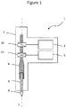
- the figure 1 shows a diagram of a drilling and milling machine 1 with advance control according to the prior art.
- This machine 1 comprises a frame 2 and a spindle 4 which extends on an axis D and carries a tool holder 6 itself carrying a tool 8 for cutting or having another utility.
- a feed motor 3 is connected to the spindle 4 by a device 30 for translating said spindle 4 with respect to the frame 2 along the axis D.
- a rotation motor 5 is connected to the spindle 4 by a device 50 of rotation of the spindle 4 around the axis D relative to the frame 2.
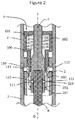
- the figure 2 shows a sectional view of the connection between the removable module 7 and the frame 2 of the machine 1 according to an implementation of the invention in the unlocked position.
- Frame 2 incorporates pin 4 and a locking and unlocking system 9.
- the locking and unlocking system 9 is composed of two sub-assemblies.
- the first sub-assembly makes it possible to lock and unlock the removable module 7 to the frame 2.
- This first sub-assembly is composed of a ring 101, of a spring 102 and of a movable part 100 in translation along the axis D
- This movable part 100 cooperates with a ball system 110 111 present on the frame 2.
- the spring 102 can be replaced by any other means storing kinetic energy intended to be released, in particular a system. with compressed fluid.
- the second sub-assembly is arranged on the end of the spindle 4 and makes it possible to lock and unlock the tool holder 6 on the spindle 4. It is composed of a part 200 movable in translation along the axis D, of a spring 202 and a ring 201 fixed on the brooch. The movable part 200 cooperates with a ball system 120 121 present on the spindle 4.
- the operator actuated the return of the spindle 4 with the feed motor 3, not shown, beyond an initial position in which the locking / unlocking system is located when a locking has just been carried out.
- the return beyond the initial position is done with a control button different from the one which activates the conventional feed for cutting operations to avoid untimely unlocking.
- the initial position can be defined as being the moment when the locking and unlocking system 9 has just been locked.
- the pin 4 drives the movable part 200 in translation until said movable part 200 comes into contact with the movable part 100.
- the translation of the pin 4 puts the spring 202 in tension through it. of the ring 201 integral with said pin 4.
- the movable part 100 is driven until contact with the ring 101 In this state, the balls 111 of the ball system 110 are not constrained towards the outside of the frame 2 by the mobile part 100.
- the mobile part 200 does not exert any constraint on the ball system 120 121. due to the presence of recesses 123 on this moving part 200.
- the ball systems 110 and 120 are not actuated, it suffices to pull on the removable module 7 to detach it from the frame 2 of the machine 1.
- the tool holder 6 being integrated or linked to the removable module 7, it is detached from the spindle 4.
- the operator can then proceed to change module 7. For this, he engages another removable module 7 and its tool holder on the frame 2 of the machine 1.
- at least one sensor 13 makes it possible to verify the presence and the correct positioning of the removable module 7 on the frame 2 and at least one sensor 16 makes it possible to verify the presence and the correct positioning of the tool holder 6 on the spindle 4.
- These sensors 13 and 16 can unlock a possible safety allowing to block the advance of the spindle 4 in the absence of the module 7 or of the tool holder 6. Then the operator can actuate the descent of the spindle 4 towards the so-called initial position which locks the module 7 and tool holder 4 on frame 2 and spindle 4.
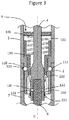
- the figure 3 shows the locked position after the spindle has returned to the initial position.
- the spindle 4 has advanced thanks to the advance motor 3, not shown.
- the spring 102 releases the accumulated energy by pushing the moving part 100 towards the ball system 110.
- the balls 111 of said system are pushed outwards and come to occupy housings 112 arranged in the internal wall of the removable module 7. This has the effect of locking the removable module 7 on the frame 2 of the machine 1.
- the translation of the spindle 4 towards the removable module 7 also releases the tension on the spring 202 which then pushes the removable part 200 on the spindle 2 in abutment towards the frame 2.
- This has the effect of putting the balls 121 under stress. of the ball system 120 and push them towards the inside of the spindle 4 so that they are housed in the housings 122 arranged in the tool holder 6.
- Said tool holder 6 is then locked to the spindle 4.
- the part 200, the spring 202 and the ring 201 are integral with the spindle 4 which makes it possible not to interfere with the control of the advance and the rotation of the spindle 4.
- the invention proposes to overcome the problems of adjusting the parameters of the machine during a tool change which is itself facilitated by this principle of modularity at the level of the head of the machine.
- the machine 1 is equipped with a data exchange system composed of a reading means 14 (not visible in the figures) present on the frame 2 of the machine 1 and of an identification means 15. (not visible in the figures) present on the removable module 7.
- a reading means 14 not visible in the figures
- an identification means 15 not visible in the figures
- These means 14 and 15 preferably use RFID contactless technology but can use another contactless or contactless technology.
- the identification means 15 contains in particular the identification data of the tool 8 carried by the tool holder 6. Usage data of said tool 8 can also be used. be contained in the means 15, in particular the number of cycles, the remaining life time. This means 15 can also include the characteristics of the tool 8 and the settings to be configured in the machine 1 for a good use of the tool 8. In another example of implementation of the invention, all this information can be. recorded in a central server connected to the machine 1 and only the identification of the removable module 7 associated with its tool 8 is contained on the identification means 15. This identification will allow the server to retrieve all information related to the removable module 7 and its tool 8.
- the reading means 14 access the data contained on the identification means 15.
- the machine 1, or a central control server interprets these data to make the adjustments necessary for the correct use of tool 8.
- the settings can for example be the feed rate of spindle 4, the number of rotations per minute, a sequence combining these two parameters, etc.
Landscapes
- Engineering & Computer Science (AREA)
- Mechanical Engineering (AREA)
- Gripping On Spindles (AREA)
- Automatic Tool Replacement In Machine Tools (AREA)
Claims (13)
- Modulare tragbare Mehrzweckmaschine (1), insbesondere zum Bohren oder Fräsen, insbesondere von Teilen, welche Flugzeugstrukturen bilden, aufweisend:- einen Rahmen (2), welcher insbesondere einen Motor (5) zum Drehen eines Werkzeugs (8) und einen Motor (3) zur Translation des Werkzeugs und eine Spindel (4) aufweist,- wobei sich die Spindel entlang einer Achse (D) erstreckt und dazu bestimmt ist, einen Werkzeughalter (6) zu halten,- wobei die Spindel (4) bezüglich des Rahmens mittels des Motors zum Drehen (5) um die Achse (D) herum dreh- und mittels des Motors zur Translation (3) entlang der Achse (D) translationsangetrieben wird, und- wobei der besagte Werkzeughalter (6) in einem abnehmbaren Modul (7) enthalten ist, welches sich mit dem Rahmen (2) verbindet, und das Werkzeug (8) hält, insbesondere zum Bohren oder Fräsen, sodass die Spindel (4) mit einem System (9) zum Verriegeln und zum Entriegeln kooperiert, um das abnehmbare Modul (7) am Rahmen (2) der Maschine (1) und seinen Werkzeughalter (6) an der Spindel (4) zu befestigen, und sodass das Verriegeln und das Entriegeln mittels einer Translationsbewegung entlang der Achse (D) von zumindest einem beweglichen Teil (100) während der Translation der Spindel (4) erreicht wird.
- Maschine (1) gemäß Anspruch 1, dadurch gekennzeichnet, dass das bewegliche Teil (100) in Zwängung an zumindest einem Kugeln-System (110) gerät beim Verriegeln des Systems (9) zum Verriegeln und zum Entriegeln.
- Maschine (1) gemäß Anspruch 2, dadurch gekennzeichnet, dass das System (9) zum Verriegeln und Entriegeln aufweist ein Kugeln-System (110), welches dazu bestimmt ist, die Ausrüstung am Rahmen (2) der Maschine (1) zu verriegeln, und ein Kugeln-System (120), welches dazu bestimmt ist, den Werkzeughalter (6) an der Spindel (4) zu verriegeln.
- Maschine (1) gemäß irgendeinem der vorherigen Ansprüche, dadurch gekennzeichnet, dass das abnehmbare Modul (7) mit einem Mittel zur Identifikation (15) ausgestattet ist, welches seine technischen Eigenschaften und seine Verwendungsdaten aufweist, und dadurch, dass die Maschine (1) ein Mittel zum Lesen (14) des besagten Mittels zur Identifikation (15) bei der Anordnung des abnehmbaren Moduls (7) am Rahmen (2) der Maschine (1) aufweist.
- Maschine (1) gemäß Anspruch 4, dadurch gekennzeichnet, dass die Mittel zur Identifikation (15) und zum Lesen (14) eine RFID-Technologie oder eine andere kontaktlose Technologie verwenden.
- Maschine (1) gemäß irgendeinem der vorherigen Ansprüche, dadurch gekennzeichnet, dass sie einen Sensor (13) aufweist, welcher dazu bestimmt ist, das Vorhandensein des abnehmbaren Moduls (7) an der Maschine (1) zu detektieren.
- Maschine (1) gemäß irgendeinem der vorherigen Ansprüche, dadurch gekennzeichnet, dass sie einen Sensor (16) aufweist, welcher dazu bestimmt ist, zu detektieren, ob der Werkzeughalter (6) an der Spindel (4) verriegelt ist.
- Verfahren zum Befestigen eines abnehmbaren Moduls (7) an einer Maschine (1), welche von irgendeinem der vorherigen Ansprüche beschrieben wird, dadurch gekennzeichnet, dass:- in der Phase des Verriegelns des abnehmbaren Moduls (7) am Rahmen (2) der Maschine (1):- das abnehmbare Modul (7) manuell am Rahmen (2) angeordnet wird, was dazu führt, dass der Werkzeughalter (6) in die Spindel (4) eingeführt wird, und- die Spindel (4) eine Translation entlang der Achse (D) zum abnehmbaren Modul (7) hin durchführt, was die Verriegelung des besagten Moduls mittels des Systems zum Verriegeln und zum Entriegeln (9) bewirkt, und- in der Phase des Entriegelns des abnehmbaren Moduls (7) vom Rahmen (2) der Maschine (1):- die Spindel (4) eine Translation entlang der Achse (D) zum Rahmen (2) hin durchführt, was die Entriegelung des abnehmbaren Moduls (7) mittels des Systems (9) zum Verriegeln und zum Entriegeln bewirkt.
- Verfahren gemäß Anspruch 8, dadurch gekennzeichnet, dass:- in der Phase des Verriegelns des abnehmbaren Moduls (7) am Rahmen (2) die Spindel (4) die Translation von zumindest einem beweglichen Teil (100) entlang der Achse (D) zum abnehmbaren Modul (7) hin erlaubt, welches die Kugeln (111) eines Kugeln-Systems (110) in die Aufnahmen (112) des abnehmbaren Moduls (7) drückt, was die Verriegelung des abnehmbaren Moduls (7) am Rahmen (2) bewirkt, und- in der Phase des Entriegelns die Spindel (4) die Translation des besagten zumindest einen beweglichen Teils (100) entlang der Achse (D) zum Rahmen (2) hin erlaubt, welches die Kugeln (111) des zumindest einen Kugeln-Systems (110) aus den Aufnahmen (112) des abnehmbaren Moduls freigibt, was die Entriegelung des abnehmbaren Moduls (7) vom Rahmen (2) bewirkt.
- Verfahren gemäß Anspruch 8, dadurch gekennzeichnet, dass ein zweites bewegliches Teil (200) die Kugeln (121) zum Verriegeln des Kugeln-Systems (120) auf dem Niveau des Einführens des Werkzeughalters (6) in die Spindel (4) während der Phase des Verriegelns blockiert und sie während der Phase des Entriegelns freigibt.
- Verfahren gemäß irgendeinem der Ansprüche 8 bis 10, dadurch gekennzeichnet, dass das Verriegeln des abnehmbaren Moduls (7) nur erfolgen kann, wenn der Sensor (13) eine Anordnung des abnehmbaren Moduls (7) am Rahmen (2) der Maschine (1) detektiert.
- Verfahren gemäß irgendeinem der Ansprüche 8 bis 11, dadurch gekennzeichnet, dass das Verriegeln des Werkzeughalters (6) an der Spindel (4) nur erfolgen kann, wenn der Sensor (16) das Vorhandensein des Werkzeughalters (6) an der Spindel (4) detektiert.
- Verfahren gemäß irgendeinem der Ansprüche 8 bis 12, dadurch gekennzeichnet, dass Informationen, insbesondere zur Identifikation oder zur Verwendung, vom abnehmbaren Modul (7) zur Maschine (1) mittels Mitteln zur Identifikation (15) und zum Lesen (14) übertragen werden, welche es der Maschine (1) erlauben, ihre Betriebseinstellungen in Abhängigkeit von Eigenschaften des abnehmbaren Moduls (7) anzupassen.
Applications Claiming Priority (2)
| Application Number | Priority Date | Filing Date | Title |
|---|---|---|---|
| FR1560898A FR3043579B1 (fr) | 2015-11-13 | 2015-11-13 | Machine portative polyvalente modulaire et procede de verrouillage et de deverrouillage d'un module amovible |
| PCT/EP2016/077597 WO2017081321A1 (fr) | 2015-11-13 | 2016-11-14 | Machine portative polyvalente modulaire et procédé de verrouillage et de déverrouillage d'un module amovible |
Publications (2)
| Publication Number | Publication Date |
|---|---|
| EP3374111A1 EP3374111A1 (de) | 2018-09-19 |
| EP3374111B1 true EP3374111B1 (de) | 2021-03-03 |
Family
ID=55236620
Family Applications (1)
| Application Number | Title | Priority Date | Filing Date |
|---|---|---|---|
| EP16798446.7A Not-in-force EP3374111B1 (de) | 2015-11-13 | 2016-11-14 | Tragbare modulare mehrzweckmaschine und verfahren zum verriegeln und entriegeln eines abnehmbaren moduls |
Country Status (3)
| Country | Link |
|---|---|
| EP (1) | EP3374111B1 (de) |
| FR (1) | FR3043579B1 (de) |
| WO (1) | WO2017081321A1 (de) |
Families Citing this family (2)
| Publication number | Priority date | Publication date | Assignee | Title |
|---|---|---|---|---|
| IT201800010747A1 (it) * | 2018-11-30 | 2020-05-30 | Gmm S P A | Gruppo portautensile di una macchina per la lavorazione di materiali in blocco o in lastra, macchina includente tale gruppo e metodo per la lavorazione di materiali in blocco o in lastra |
| FR3117052B1 (fr) * | 2020-12-03 | 2023-02-24 | Renault Georges Ets | Dispositif de perçage à moyens de mesure des forces de poussée axiales. |
Family Cites Families (5)
| Publication number | Priority date | Publication date | Assignee | Title |
|---|---|---|---|---|
| FR2703280B1 (fr) * | 1993-04-02 | 1996-07-12 | Recoules Fils Ets | Procédé et dispositif de montage d'outillages. |
| CN102161192A (zh) * | 2010-02-23 | 2011-08-24 | 车王电子股份有限公司 | 电动工具及其扭力调整方法 |
| DE102013213806A1 (de) * | 2012-11-15 | 2014-05-15 | Robert Bosch Gmbh | Werkzeugvorsatz für eine Handwerkzeugmaschine |
| US10011008B2 (en) * | 2012-11-15 | 2018-07-03 | Robert Bosch Gmbh | Tool attachment for a hand-held machine tool |
| FR3025125B1 (fr) * | 2014-09-02 | 2017-03-24 | Renault Georges Ets | Dispositif de percage pneumatique a moyens de production d'electricite |
-
2015
- 2015-11-13 FR FR1560898A patent/FR3043579B1/fr not_active Expired - Fee Related
-
2016
- 2016-11-14 WO PCT/EP2016/077597 patent/WO2017081321A1/fr not_active Ceased
- 2016-11-14 EP EP16798446.7A patent/EP3374111B1/de not_active Not-in-force
Non-Patent Citations (1)
| Title |
|---|
| None * |
Also Published As
| Publication number | Publication date |
|---|---|
| FR3043579B1 (fr) | 2018-05-25 |
| WO2017081321A1 (fr) | 2017-05-18 |
| EP3374111A1 (de) | 2018-09-19 |
| FR3043579A1 (fr) | 2017-05-19 |
Similar Documents
| Publication | Publication Date | Title |
|---|---|---|
| EP2105249B1 (de) | Bearbeitungsmaschine mit mechanischem Vorschub und Bearbeitungsverfahren | |
| BE1016957A6 (fr) | Dispositif et procede pour l'assemblage par rivetage de toles. | |
| EP2754531B1 (de) | Zweimotorige Bohrmaschine mit kontrolliertem Vorschub | |
| EP3374111B1 (de) | Tragbare modulare mehrzweckmaschine und verfahren zum verriegeln und entriegeln eines abnehmbaren moduls | |
| CN102152136A (zh) | 自定心固定架 | |
| FR2558753A1 (fr) | Cassette porte-outil a vitesse rapide adaptable sur des perceuses, fraiseuses ou autres machines-outils similaires | |
| EP1618978A1 (de) | Werkzeugmaschine mit mechanischem Vorschub welche ein Ausräumen der Späne ermöglicht | |
| EP2498938B1 (de) | Gewindebohrer mit schutzmittel | |
| EP1493529B1 (de) | Montagemaschine mit einem Montagewerkzeuge tragenden Revolver | |
| EP3666432B1 (de) | Vorrichtung zur festen verbindung einer bohrvorrichtung mit einem bohrgitter, das einen kugelspannsatz umfasst | |
| EP2731755B1 (de) | Verfahren zur zentrierung von werkzeugen an einer bearbeitungsvorrichtung und zentrierhilfe zur durchführung dieses verfahrens | |
| EP2570863B1 (de) | Uhren-Federgehäuse mit reduziertem Durchmesser des Bundes | |
| WO2012013633A1 (fr) | Dispositif d'avivage de meule de travail et son utilisation dans une rectifieuse sans centre de pastilles de combustible nucleaire | |
| EP3307462B1 (de) | Drehmaschine und führungsbuchse | |
| FR3065894A1 (fr) | Procede automatise de sertissage de bague et pistolet de mise en oeuvre | |
| EP1595614B1 (de) | Stanzmaschine | |
| EP1999525B1 (de) | Montageverfahren mittels plattennietung | |
| EP3476729B1 (de) | Verfahren und vorrichtung zur leistungsoptimierung in einer motoranlage | |
| FR3056745A1 (fr) | Cle dynanometrique a debattement amorti par voie hydraulique, avec ou sans butee de limitation angulaire | |
| FR2871561A1 (fr) | Dispositif de detection de l'etat de fermeture d'une culasse d'arme | |
| FR3140568A1 (fr) | Système de travail de pièce comprenant une machine-outil, et procédé de travail correspondant | |
| FR3057481B1 (fr) | "outil pour usiner et galeter un trou perce, procede mis en œuvre au moyen d'un tel outil et piece obtenue par la mise en œuvre d'un tel procede" | |
| FR3147247A1 (fr) | Dispositif de compensation pour le verrouillage axial d’un premier élément tubulaire reçu à ajustement dans un deuxième élément tubulaire | |
| FR2665856A1 (fr) | Machine-outil a remplacement automatique des tetes revolver, et mecanisme associe d'indexage des tetes revolver. | |
| EP0086127A1 (de) | Hydraulische Anlage zum Abbremsen und Verriegeln, sowie deren Verwednung in automatischen Geschützladevorrichtungen |
Legal Events
| Date | Code | Title | Description |
|---|---|---|---|
| STAA | Information on the status of an ep patent application or granted ep patent |
Free format text: STATUS: UNKNOWN |
|
| STAA | Information on the status of an ep patent application or granted ep patent |
Free format text: STATUS: THE INTERNATIONAL PUBLICATION HAS BEEN MADE |
|
| PUAI | Public reference made under article 153(3) epc to a published international application that has entered the european phase |
Free format text: ORIGINAL CODE: 0009012 |
|
| STAA | Information on the status of an ep patent application or granted ep patent |
Free format text: STATUS: REQUEST FOR EXAMINATION WAS MADE |
|
| 17P | Request for examination filed |
Effective date: 20180604 |
|
| AK | Designated contracting states |
Kind code of ref document: A1 Designated state(s): AL AT BE BG CH CY CZ DE DK EE ES FI FR GB GR HR HU IE IS IT LI LT LU LV MC MK MT NL NO PL PT RO RS SE SI SK SM TR |
|
| AX | Request for extension of the european patent |
Extension state: BA ME |
|
| DAV | Request for validation of the european patent (deleted) | ||
| DAX | Request for extension of the european patent (deleted) | ||
| REG | Reference to a national code |
Ref country code: DE Ref legal event code: R079 Ref document number: 602016053674 Country of ref document: DE Free format text: PREVIOUS MAIN CLASS: B23B0045000000 Ipc: B23Q0005320000 |
|
| GRAP | Despatch of communication of intention to grant a patent |
Free format text: ORIGINAL CODE: EPIDOSNIGR1 |
|
| STAA | Information on the status of an ep patent application or granted ep patent |
Free format text: STATUS: GRANT OF PATENT IS INTENDED |
|
| RIC1 | Information provided on ipc code assigned before grant |
Ipc: B23Q 5/32 20060101AFI20200831BHEP |
|
| INTG | Intention to grant announced |
Effective date: 20201001 |
|
| GRAS | Grant fee paid |
Free format text: ORIGINAL CODE: EPIDOSNIGR3 |
|
| GRAA | (expected) grant |
Free format text: ORIGINAL CODE: 0009210 |
|
| STAA | Information on the status of an ep patent application or granted ep patent |
Free format text: STATUS: THE PATENT HAS BEEN GRANTED |
|
| AK | Designated contracting states |
Kind code of ref document: B1 Designated state(s): AL AT BE BG CH CY CZ DE DK EE ES FI FR GB GR HR HU IE IS IT LI LT LU LV MC MK MT NL NO PL PT RO RS SE SI SK SM TR |
|
| REG | Reference to a national code |
Ref country code: GB Ref legal event code: FG4D Free format text: NOT ENGLISH |
|
| REG | Reference to a national code |
Ref country code: AT Ref legal event code: REF Ref document number: 1366680 Country of ref document: AT Kind code of ref document: T Effective date: 20210315 Ref country code: CH Ref legal event code: EP |
|
| REG | Reference to a national code |
Ref country code: DE Ref legal event code: R096 Ref document number: 602016053674 Country of ref document: DE |
|
| REG | Reference to a national code |
Ref country code: IE Ref legal event code: FG4D Free format text: LANGUAGE OF EP DOCUMENT: FRENCH |
|
| REG | Reference to a national code |
Ref country code: LT Ref legal event code: MG9D |
|
| PG25 | Lapsed in a contracting state [announced via postgrant information from national office to epo] |
Ref country code: NO Free format text: LAPSE BECAUSE OF FAILURE TO SUBMIT A TRANSLATION OF THE DESCRIPTION OR TO PAY THE FEE WITHIN THE PRESCRIBED TIME-LIMIT Effective date: 20210603 Ref country code: GR Free format text: LAPSE BECAUSE OF FAILURE TO SUBMIT A TRANSLATION OF THE DESCRIPTION OR TO PAY THE FEE WITHIN THE PRESCRIBED TIME-LIMIT Effective date: 20210604 Ref country code: FI Free format text: LAPSE BECAUSE OF FAILURE TO SUBMIT A TRANSLATION OF THE DESCRIPTION OR TO PAY THE FEE WITHIN THE PRESCRIBED TIME-LIMIT Effective date: 20210303 Ref country code: HR Free format text: LAPSE BECAUSE OF FAILURE TO SUBMIT A TRANSLATION OF THE DESCRIPTION OR TO PAY THE FEE WITHIN THE PRESCRIBED TIME-LIMIT Effective date: 20210303 Ref country code: BG Free format text: LAPSE BECAUSE OF FAILURE TO SUBMIT A TRANSLATION OF THE DESCRIPTION OR TO PAY THE FEE WITHIN THE PRESCRIBED TIME-LIMIT Effective date: 20210603 Ref country code: LT Free format text: LAPSE BECAUSE OF FAILURE TO SUBMIT A TRANSLATION OF THE DESCRIPTION OR TO PAY THE FEE WITHIN THE PRESCRIBED TIME-LIMIT Effective date: 20210303 |
|
| REG | Reference to a national code |
Ref country code: NL Ref legal event code: MP Effective date: 20210303 |
|
| REG | Reference to a national code |
Ref country code: AT Ref legal event code: MK05 Ref document number: 1366680 Country of ref document: AT Kind code of ref document: T Effective date: 20210303 |
|
| PG25 | Lapsed in a contracting state [announced via postgrant information from national office to epo] |
Ref country code: LV Free format text: LAPSE BECAUSE OF FAILURE TO SUBMIT A TRANSLATION OF THE DESCRIPTION OR TO PAY THE FEE WITHIN THE PRESCRIBED TIME-LIMIT Effective date: 20210303 Ref country code: RS Free format text: LAPSE BECAUSE OF FAILURE TO SUBMIT A TRANSLATION OF THE DESCRIPTION OR TO PAY THE FEE WITHIN THE PRESCRIBED TIME-LIMIT Effective date: 20210303 Ref country code: PL Free format text: LAPSE BECAUSE OF FAILURE TO SUBMIT A TRANSLATION OF THE DESCRIPTION OR TO PAY THE FEE WITHIN THE PRESCRIBED TIME-LIMIT Effective date: 20210303 Ref country code: SE Free format text: LAPSE BECAUSE OF FAILURE TO SUBMIT A TRANSLATION OF THE DESCRIPTION OR TO PAY THE FEE WITHIN THE PRESCRIBED TIME-LIMIT Effective date: 20210303 |
|
| PG25 | Lapsed in a contracting state [announced via postgrant information from national office to epo] |
Ref country code: NL Free format text: LAPSE BECAUSE OF FAILURE TO SUBMIT A TRANSLATION OF THE DESCRIPTION OR TO PAY THE FEE WITHIN THE PRESCRIBED TIME-LIMIT Effective date: 20210303 |
|
| PG25 | Lapsed in a contracting state [announced via postgrant information from national office to epo] |
Ref country code: CZ Free format text: LAPSE BECAUSE OF FAILURE TO SUBMIT A TRANSLATION OF THE DESCRIPTION OR TO PAY THE FEE WITHIN THE PRESCRIBED TIME-LIMIT Effective date: 20210303 Ref country code: EE Free format text: LAPSE BECAUSE OF FAILURE TO SUBMIT A TRANSLATION OF THE DESCRIPTION OR TO PAY THE FEE WITHIN THE PRESCRIBED TIME-LIMIT Effective date: 20210303 Ref country code: SM Free format text: LAPSE BECAUSE OF FAILURE TO SUBMIT A TRANSLATION OF THE DESCRIPTION OR TO PAY THE FEE WITHIN THE PRESCRIBED TIME-LIMIT Effective date: 20210303 Ref country code: AT Free format text: LAPSE BECAUSE OF FAILURE TO SUBMIT A TRANSLATION OF THE DESCRIPTION OR TO PAY THE FEE WITHIN THE PRESCRIBED TIME-LIMIT Effective date: 20210303 |
|
| PG25 | Lapsed in a contracting state [announced via postgrant information from national office to epo] |
Ref country code: IS Free format text: LAPSE BECAUSE OF FAILURE TO SUBMIT A TRANSLATION OF THE DESCRIPTION OR TO PAY THE FEE WITHIN THE PRESCRIBED TIME-LIMIT Effective date: 20210703 Ref country code: PT Free format text: LAPSE BECAUSE OF FAILURE TO SUBMIT A TRANSLATION OF THE DESCRIPTION OR TO PAY THE FEE WITHIN THE PRESCRIBED TIME-LIMIT Effective date: 20210705 Ref country code: RO Free format text: LAPSE BECAUSE OF FAILURE TO SUBMIT A TRANSLATION OF THE DESCRIPTION OR TO PAY THE FEE WITHIN THE PRESCRIBED TIME-LIMIT Effective date: 20210303 Ref country code: SK Free format text: LAPSE BECAUSE OF FAILURE TO SUBMIT A TRANSLATION OF THE DESCRIPTION OR TO PAY THE FEE WITHIN THE PRESCRIBED TIME-LIMIT Effective date: 20210303 |
|
| REG | Reference to a national code |
Ref country code: DE Ref legal event code: R097 Ref document number: 602016053674 Country of ref document: DE |
|
| PLBE | No opposition filed within time limit |
Free format text: ORIGINAL CODE: 0009261 |
|
| STAA | Information on the status of an ep patent application or granted ep patent |
Free format text: STATUS: NO OPPOSITION FILED WITHIN TIME LIMIT |
|
| PG25 | Lapsed in a contracting state [announced via postgrant information from national office to epo] |
Ref country code: ES Free format text: LAPSE BECAUSE OF FAILURE TO SUBMIT A TRANSLATION OF THE DESCRIPTION OR TO PAY THE FEE WITHIN THE PRESCRIBED TIME-LIMIT Effective date: 20210303 Ref country code: DK Free format text: LAPSE BECAUSE OF FAILURE TO SUBMIT A TRANSLATION OF THE DESCRIPTION OR TO PAY THE FEE WITHIN THE PRESCRIBED TIME-LIMIT Effective date: 20210303 Ref country code: AL Free format text: LAPSE BECAUSE OF FAILURE TO SUBMIT A TRANSLATION OF THE DESCRIPTION OR TO PAY THE FEE WITHIN THE PRESCRIBED TIME-LIMIT Effective date: 20210303 |
|
| 26N | No opposition filed |
Effective date: 20211206 |
|
| PG25 | Lapsed in a contracting state [announced via postgrant information from national office to epo] |
Ref country code: SI Free format text: LAPSE BECAUSE OF FAILURE TO SUBMIT A TRANSLATION OF THE DESCRIPTION OR TO PAY THE FEE WITHIN THE PRESCRIBED TIME-LIMIT Effective date: 20210303 |
|
| PG25 | Lapsed in a contracting state [announced via postgrant information from national office to epo] |
Ref country code: IT Free format text: LAPSE BECAUSE OF FAILURE TO SUBMIT A TRANSLATION OF THE DESCRIPTION OR TO PAY THE FEE WITHIN THE PRESCRIBED TIME-LIMIT Effective date: 20210303 |
|
| PG25 | Lapsed in a contracting state [announced via postgrant information from national office to epo] |
Ref country code: IS Free format text: LAPSE BECAUSE OF FAILURE TO SUBMIT A TRANSLATION OF THE DESCRIPTION OR TO PAY THE FEE WITHIN THE PRESCRIBED TIME-LIMIT Effective date: 20210703 |
|
| REG | Reference to a national code |
Ref country code: DE Ref legal event code: R119 Ref document number: 602016053674 Country of ref document: DE |
|
| PG25 | Lapsed in a contracting state [announced via postgrant information from national office to epo] |
Ref country code: MC Free format text: LAPSE BECAUSE OF FAILURE TO SUBMIT A TRANSLATION OF THE DESCRIPTION OR TO PAY THE FEE WITHIN THE PRESCRIBED TIME-LIMIT Effective date: 20210303 |
|
| REG | Reference to a national code |
Ref country code: CH Ref legal event code: PL |
|
| GBPC | Gb: european patent ceased through non-payment of renewal fee |
Effective date: 20211114 |
|
| PG25 | Lapsed in a contracting state [announced via postgrant information from national office to epo] |
Ref country code: LU Free format text: LAPSE BECAUSE OF NON-PAYMENT OF DUE FEES Effective date: 20211114 Ref country code: BE Free format text: LAPSE BECAUSE OF NON-PAYMENT OF DUE FEES Effective date: 20211130 |
|
| REG | Reference to a national code |
Ref country code: BE Ref legal event code: MM Effective date: 20211130 |
|
| PG25 | Lapsed in a contracting state [announced via postgrant information from national office to epo] |
Ref country code: IE Free format text: LAPSE BECAUSE OF NON-PAYMENT OF DUE FEES Effective date: 20211114 Ref country code: GB Free format text: LAPSE BECAUSE OF NON-PAYMENT OF DUE FEES Effective date: 20211114 Ref country code: DE Free format text: LAPSE BECAUSE OF NON-PAYMENT OF DUE FEES Effective date: 20220601 |
|
| PG25 | Lapsed in a contracting state [announced via postgrant information from national office to epo] |
Ref country code: FR Free format text: LAPSE BECAUSE OF NON-PAYMENT OF DUE FEES Effective date: 20211130 |
|
| PG25 | Lapsed in a contracting state [announced via postgrant information from national office to epo] |
Ref country code: HU Free format text: LAPSE BECAUSE OF FAILURE TO SUBMIT A TRANSLATION OF THE DESCRIPTION OR TO PAY THE FEE WITHIN THE PRESCRIBED TIME-LIMIT; INVALID AB INITIO Effective date: 20161114 |
|
| PG25 | Lapsed in a contracting state [announced via postgrant information from national office to epo] |
Ref country code: CY Free format text: LAPSE BECAUSE OF FAILURE TO SUBMIT A TRANSLATION OF THE DESCRIPTION OR TO PAY THE FEE WITHIN THE PRESCRIBED TIME-LIMIT Effective date: 20210303 |
|
| PG25 | Lapsed in a contracting state [announced via postgrant information from national office to epo] |
Ref country code: LI Free format text: LAPSE BECAUSE OF NON-PAYMENT OF DUE FEES Effective date: 20220630 Ref country code: CH Free format text: LAPSE BECAUSE OF NON-PAYMENT OF DUE FEES Effective date: 20220630 |
|
| PG25 | Lapsed in a contracting state [announced via postgrant information from national office to epo] |
Ref country code: MK Free format text: LAPSE BECAUSE OF FAILURE TO SUBMIT A TRANSLATION OF THE DESCRIPTION OR TO PAY THE FEE WITHIN THE PRESCRIBED TIME-LIMIT Effective date: 20210303 |
|
| PG25 | Lapsed in a contracting state [announced via postgrant information from national office to epo] |
Ref country code: MT Free format text: LAPSE BECAUSE OF FAILURE TO SUBMIT A TRANSLATION OF THE DESCRIPTION OR TO PAY THE FEE WITHIN THE PRESCRIBED TIME-LIMIT Effective date: 20210303 |
|
| PG25 | Lapsed in a contracting state [announced via postgrant information from national office to epo] |
Ref country code: TR Free format text: LAPSE BECAUSE OF FAILURE TO SUBMIT A TRANSLATION OF THE DESCRIPTION OR TO PAY THE FEE WITHIN THE PRESCRIBED TIME-LIMIT Effective date: 20210303 |